ford plastic pit setters - the ford meter box company principles of meter pit design one of the most...
TRANSCRIPT
Section FA 02/2015
Web Revision 12/21/2017
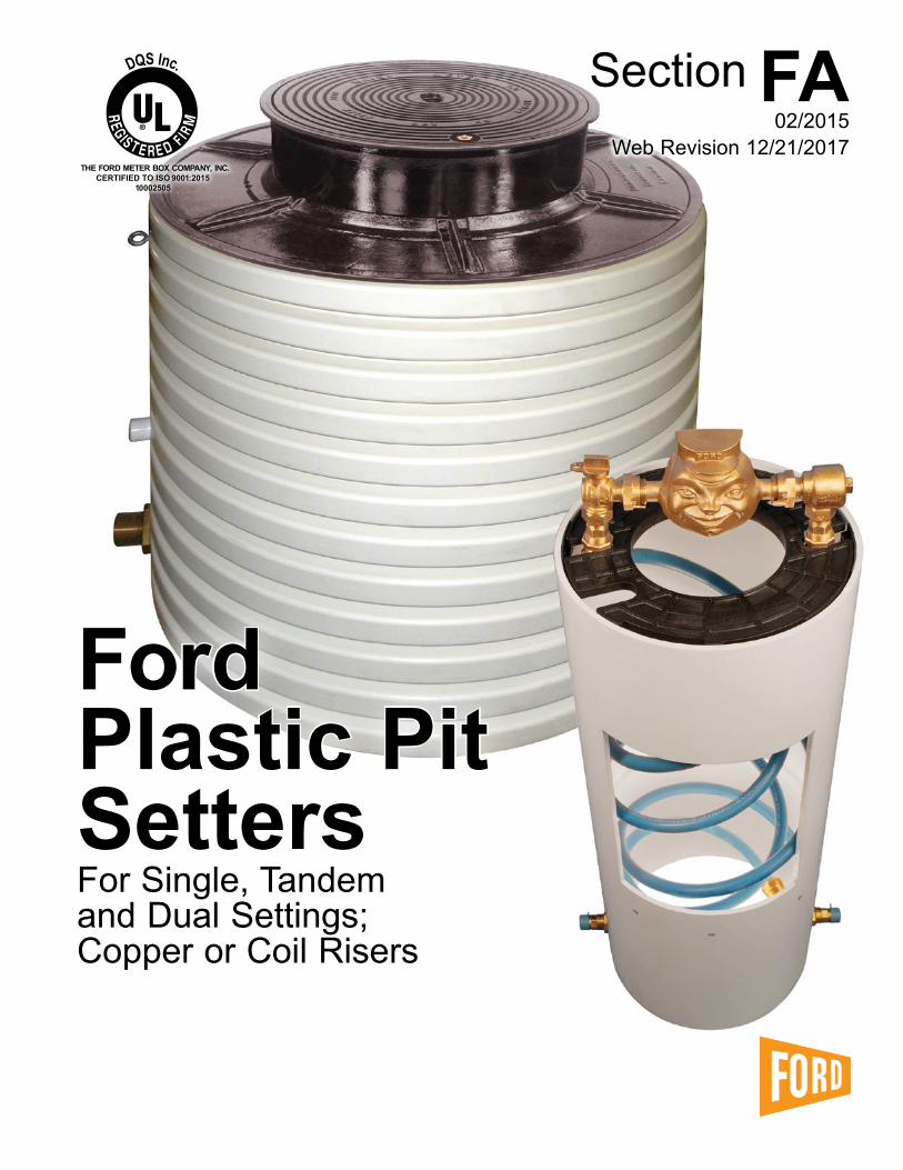
FordPlastic PitSettersFor Single, Tandemand Dual Settings;Copper or Coil Risers
DQS Inc.
THE FORD METER BOX COMPANY, INC.CERTIFIED TO ISO 9001:2015
10002505

FA-2

FA-3
Contents Page
Plastic Pits Ford Plastic Pit Setter Numbering System . . . . . . . . . . . . . . . . . . . . . . . . . . . . . . . . . . . . . 4 Introduction . . . . . . . . . . . . . . . . . . . . . . . . . . . . . . . . . . . . . . . . . . . . . . . . . . . . . . . . . . . . . . 5 Principles of Meter Pit Design . . . . . . . . . . . . . . . . . . . . . . . . . . . . . . . . . . . . . . . . . . . . . . . 5 5/8", 5/8"x3/4", 3/4" and 1" Plastic Pit Setter for Moderate to Cold Climates How to Order a Plastic Pit Setter . . . . . . . . . . . . . . . . . . . . . . . . . . . . . . . . . . . . . . . . . . 6 - 9 Single Lid Type (Vertical Measurements) . . . . . . . . . . . . . . . . . . . . . . . . . . . . . . . . . . . . . . 10 Double Lid Type (Vertical Measurements) . . . . . . . . . . . . . . . . . . . . . . . . . . . . . . . . . . . . . 11 1-1/2" and 2" Plastic Pit Setters How to Order a 1-1/2" or 2" Pit Setter . . . . . . . . . . . . . . . . . . . . . . . . . . . . . . . . . . . . . 12, 13 Monitor Lid Pit Setters (Vertical Measurements) . . . . . . . . . . . . . . . . . . . . . . . . . . . . . . . . 14 Single Lid Pit Setters (Vertical Measurements) . . . . . . . . . . . . . . . . . . . . . . . . . . . . . . . . . 15 Double Lid Pit Setters (Vertical Measurements) . . . . . . . . . . . . . . . . . . . . . . . . . . . . . . . . 15 How to Order a Cover . . . . . . . . . . . . . . . . . . . . . . . . . . . . . . . . . . . . . . . . . . . . . . . . . . 16, 17 Style “K” Pit Setter for Mild Climates (5/8"x3/4" Meter) The Standard 15" Diameter Style “K” . . . . . . . . . . . . . . . . . . . . . . . . . . . . . . . . . . . . . . . . 18 The 15" Diameter Style “K” for Dual Meter Setting . . . . . . . . . . . . . . . . . . . . . . . . . . . . . . 19
Coil Pits The Ford Coil Pit Setter . . . . . . . . . . . . . . . . . . . . . . . . . . . . . . . . . . . . . . . . . . . . . . . . . . . . 20 The Ford Coil Pit Setter Numbering System . . . . . . . . . . . . . . . . . . . . . . . . . . . . . . . . . . . 21 Standard Specifications . . . . . . . . . . . . . . . . . . . . . . . . . . . . . . . . . . . . . . . . . . . . . . . . . . . 21 15" Diameter Coil Pit Setters with Single or Tandem Settings for 5/8" or 5/8" x 3/4" Meters . . . . . . . . . . . . . . . . . . . . . . . . . . . . . . . . . . . . . . . . . . . . . . . 22 18" Diameter Coil Pit Setters with Dual Settings for 5/8", 5/8" x 3/4" or 3/4" Meters . . . . . . . . . . . . . . . . . . . . . . . . . . . . . . . . . . . . . . . . . . 22 18" Diameter Coil Pit Setters with Single or Tandem Settings for 5/8", 5/8" x 3/4", 3/4" or 1" Meters . . . . . . . . . . . . . . . . . . . . . . . . . . . . . . . . . . . . . . . . 23 Features . . . . . . . . . . . . . . . . . . . . . . . . . . . . . . . . . . . . . . . . . . . . . . . . . . . . . . . . . . . . . . . 24 Optional Items for Coil Pit Setters Coil Pit Setter Lids, Covers and Insulating Discs . . . . . . . . . . . . . . . . . . . . . . . . . . . . . . . . 25 Coil Pit Setter Access Rods, Extension Rings and Bottom Plates . . . . . . . . . . . . . . . . . . 26 Coil Pit Setter Installation Instructions . . . . . . . . . . . . . . . . . . . . . . . . . . . . . . . . . . . . . . . 27 Warranty . . . . . . . . . . . . . . . . . . . . . . . . . . . . . . . . . . . . . . . . . . . . . . . . . . . . . . . . . . . . . . . . 28
Due to design improvements, product images in the catalog do not always reflect the most current design detail .
FA-4
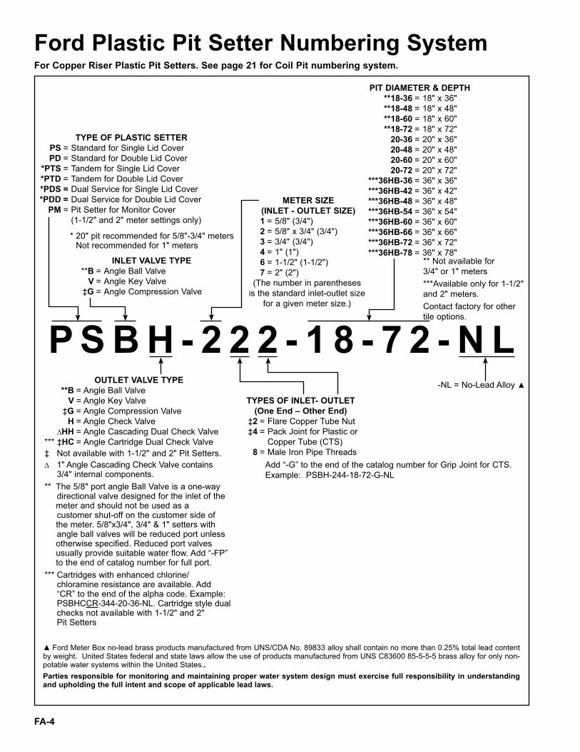
P S B H - 2 2 2 - 1 8 - 7 2 - N L
TYPE OF PLASTIC SETTER PS = Standard for Single Lid Cover PD = Standard for Double Lid Cover *PTS = Tandem for Single Lid Cover *PTD = Tandem for Double Lid Cover *PDS = Dual Service for Single Lid Cover *PDD = Dual Service for Double Lid Cover PM = Pit Setter for Monitor Cover (1-1/2" and 2" meter settings only)
TYPES OF INLET- OUTLET(One End – Other End)
‡2 = Flare Copper Tube Nut ‡4 = Pack Joint for Plastic or Copper Tube (CTS) 8 = Male Iron Pipe Threads
METER SIZE (INLET - OUTLET SIZE)
1 = 5/8" (3/4") 2 = 5/8" x 3/4" (3/4") 3 = 3/4" (3/4") 4 = 1" (1") 6 = 1-1/2" (1-1/2") 7 = 2" (2")
(The number in parentheses is the standard inlet-outlet size
for a given meter size .)
INLET VALVE TYPE **B = Angle Ball Valve V = Angle Key Valve ‡G = Angle Compression Valve
OUTLET VALVE TYPE **B = Angle Ball Valve V = Angle Key Valve ‡G = Angle Compression Valve H = Angle Check Valve ∆HH = Angle Cascading Dual Check Valve *** ‡HC = Angle Cartridge Dual Check Valve‡ Not available with 1-1/2" and 2" Pit Setters .∆ 1" Angle Cascading Check Valve contains 3/4" internal components .** The 5/8" port angle Ball Valve is a one-way
directional valve designed for the inlet of the meter and should not be used as a
customer shut-off on the customer side of the meter . 5/8"x3/4", 3/4" & 1" setters with
angle ball valves will be reduced port unless otherwise specified . Reduced port valves usually provide suitable water flow . Add “-FP” to the end of catalog number for full port .
*** Cartridges with enhanced chlorine/ chloramine resistance are available . Add “CR” to the end of the alpha code . Example: PSBHCCR-344-20-36-NL . Cartridge style dual checks not available with 1-1/2" and 2" Pit Setters
PIT DIAMETER & DEPTH **18-36 = 18" x 36" **18-48 = 18" x 48" **18-60 = 18" x 60" **18-72 = 18" x 72" 20-36 = 20" x 36" 20-48 = 20" x 48" 20-60 = 20" x 60" 20-72 = 20" x 72" ***36HB-36 = 36" x 36" ***36HB-42 = 36" x 42" ***36HB-48 = 36" x 48" ***36HB-54 = 36" x 54" ***36HB-60 = 36" x 60" ***36HB-66 = 36" x 66" ***36HB-72 = 36" x 72" ***36HB-78 = 36" x 78"
* 20" pit recommended for 5/8"-3/4" meters Not recommended for 1" meters
** Not available for3/4" or 1" meters***Available only for 1-1/2"and 2" meters .Contact factory for othertile options .
Add “-G” to the end of the catalog number for Grip Joint for CTS .Example: PSBH-244-18-72-G-NL
Ford Plastic Pit Setter Numbering SystemFor Copper Riser Plastic Pit Setters. See page 21 for Coil Pit numbering system.
▲Ford Meter Box no-lead brass products manufactured from UNS/CDA No . 89833 alloy shall contain no more than 0 .25% total lead content by weight . United States federal and state laws allow the use of products manufactured from UNS C83600 85-5-5-5 brass alloy for only non-potable water systems within the United States .. Parties responsible for monitoring and maintaining proper water system design must exercise full responsibility in understanding and upholding the full intent and scope of applicable lead laws.
-NL = No-Lead Alloy ▲

FA-5
Principles of Meter Pit Design One of the most important jobs of a meter pit setting in northern climates is to prevent meter and service line freeze-ups during the winter months . Several factors affect freezing in meter pits . These are air temperature, snow cover, the type of soil, the temperature of the service water, and the frequency of customer water consumption . The theory of pit design is that the depth of the service shall be below that of the lowest frost line and the heat from the base of the meter pit shall circulate and keep the meter setting above it from freezing . If the base of the meter pit is above the frost line, the only thing that would keep the meter from freezing is the continuous use of the service during the winter months .
Not only should meter pits be deep, but they also should be sufficiently wide . Larger diameter pits may allow a greater loss of heat through the pit walls, but that is more than compensated for by the increased amount of warm air generated by warm soil exposed at the base of the pit . Furthermore, the large diameter provides greater clearance between the cold pit walls and the riser pipes . If these pipes are allowed to touch the walls, the pipes will freeze, the flow of water will be stopped, meter and valve damage will be the likely result . In the Ford Plastic Pit Setter, the service lines are kept at a minimum of 2" from the pit wall, thus providing this important protection .
The top of the pit is equally important . In colder climates, a double lid cover such as our Wabash Cover is desirable, as it provides a dead air space between the top lid and the interior of the pit . This “dead air” acts as an insulator, retaining ground heat and keeping outside cold from entering . The Ford Plastic Pit Setter offers the Wabash Cover as an option, also available are single lid iron covers or single lid plastic covers for climates that are less severe . Most Ford covers are “hat shaped” (wider at the base than at the top) which exposes as little surface area as possible to the cold outside air . Flat cast iron covers, for mild climates, are also available . See Ford Catalog Section D .
In summary, the basic points of meter pit design provided by Ford Plastic Pit Setters are as follows: (1) Keep the meter pit depth below the deepest frost penetration line; (2) Keep the meter pit diameter sufficiently large to provide a good base of warm soil as well as to prevent pipe from freezing due to “frost jump” from the pit walls; (3) Use a hat shaped meter pit cover, with an inner lid where necessary .
These pit setting principles have been proven in over a century of outdoor pit design . The Ford Plastic Pit Setter is designed around these conservative principles in order that you, the utility customer, will not be faced with the expense of frozen services and unhappy customers . Remember—don’t cut corners with pit settings that are too shallow or too small in diameter .
Introduction The setting of meters outdoors in covered pits is an idea that dates back to the late 19th century when Edwin Ford, founder of The Ford Meter Box Company, Inc ., first utilized this principle to meter the town of Hartford City, Indiana . Mr . Ford’s idea has been modified extensively over the intervening years, but the pit setting remains one of the most popular ways of installing meters .
Outdoor meter pit settings offer the utility a number of advantages, including easy access to the meter, protection and control of the meter setting device and a clear division of responsibility for maintaining the utility’s and the customer’s service line . However, cost considerations have led many utilities to install pit settings that have been less than satisfactory and which become maintenance and freeze-up problems .
Introduced in 1981, the Ford Plastic Pit Setter offers a real cost-saving alternative to the standard “build-your-own” pit setting . Constructed of high-quality 15", 18", 20" or 36" PVC pipe, the Plastic Pit Setter has the service lines attached firmly to the pit walls, with all the valves and meter coupling materials necessary to install the meter as part of the total package . Installation of the Ford Plastic Pit Setter is easy . Simply dig an appropriately sized hole, connect your inlet and outlet piping to the connections at the bottom of the box, place a cover on top, and complete the job of installing a meter .
In the pages that follow, we will describe the principles of a good meter setting device and offer engineering drawings of standard plastic pit type settings . We are not limited to the styles and sizes shown in this catalog section . Our production methods allow us to custom build plastic pit settings for practically any conceivable requirement .

FA-6
Plastic Pit Setter for Moderate to Cold ClimatesFor 5/8", 5/8"x3/4", 3/4" and 1" MetersHow To Order A Plastic Pit Setter
Outlet Valve
ServiceLineDepth
InletValve
Type of Pit Setting(Cover type - see note below)
Type ofOutlet
Connection
Type ofInlet
Connection
MeterSize
Pit Diameter
Top Lid OnlyInner Lidfor WabashDouble Lid style only
Frame Only
Both Items make a Cover
NOTE: A wide variety of 18" and 20" covers can be purchased for Plastic Pit Setters . A complete selection of covers with their specifications and available options are listed in Ford Catalog Section D and must be ordered separately . An abbreviated selection of covers is shown on pages FA-16 and FA-17 of this catalog section .
1
2
4
5
3
7
7 6
See pages 10 & 11 for configuration and dimensional information .

FA-7
1
2
5
3 4
7
7
6
Plastic Pit Setter for Moderate to Cold ClimatesFor 5/8" or 5/8"x3/4" Meters
How To Order A Plastic Pit Setter
HOW TO ORDER A PLASTIC PIT SETTER : Answer each question to create a catalog number . The catalog codes will build the Plastic Pit Setter that meets your setting requirements .PART NUMBER EXAMPLE: PSBH-222-18-72-NL = a standard single lid style plastic pit setter with an inlet angle ball valve, outlet angle check valve, 5/8"x3/4" meter, inlet connection for flared copper, outlet connection for flared copper and a pit diameter and depth of 18"x72" . A variety of inlet and outlet couplings for copper, PEP, PVC and lead are available . See catalog section J . Engineering drawings are available for standard and/or custom pit setter designs .Note: Inlet and outlet connections are 3/4" in size, for 5/8", and 5/8"x3/4" meter settings on 5/8" x 3/4" dual setters, inlet will be 1" with two 3/4" outlets, unless otherwise specified . Female iron pipe by Pack Joint couplings are available for a variety of inlet/outlet combinations (see catalog section J) and are sold separately .Covers are sold separately in catalog section D .
Setting Type CodeStandard for Single Lid Cover PSStandard for Double Lid Cover PD
*** Tandem for Single Lid Cover PTS*** Tandem for Double Lid Cover PTD*** Dual Service Line for Single Lid Cover PDS*** Dual Service Line for Double Lid Cover PDD
Inlet Valve Type CodeAngle Key Valve V
▼ Angle Ball Valve BAngle Compression Valve GNo Inlet Valve -
Outlet Valve Type Code▼ Angle Ball Valve B
Angle Key Valve VAngle Compression Valve GAngle Check Valve HAngle Dual Check Valve HH
* Angle Cartridge Dual Check Valve HCNo Outlet Valve -
Meter Size Code5/8" Meter 15/8" x 3/4" Meter 2 3/4" Inlet Type CodeFlared Copper 2PET/CTS Pack Joint 4
♦ Male Iron Pipe 8 3/4" Outlet Type CodeFlared Copper 2PET/CTS Pack Joint 4Male Iron Pipe 8
♦1" MIP inlet only on 5/8" x 3/4" Dual Setters
Pit Diameter and Depth Smooth Wall Tile Corrugated TileCode Code
18" x 36" 18-36-NL 18C-36-NL18" x 48" 18-48-NL 18C-48-NL18" x 60" 18-60-NL 18C-60-NL18" x 72" 18-72-NL 18C-72-NL20" x 36" 20-36-NL **20C-36-NL20" x 48" 20-48-NL **20C-48-NL20" x 60" 20-60-NL **20C-60-NL20" x 72" 20-72-NL **20C-72-NL
Contact factory for other pit dimensions and types not listed . * Cartridges available with enhanced chlorine/chloramine resistance . Add “CR” to the end of the alpha code . Example: PSBCHCR-288-20-36-NL .Grip Joint for CTS and PEP can be ordered by adding “-G” to the catalog number . ** Pitsetters manufactured from 20" corrugated tile require Ford iron covers for 21" ID Tile . *** 20" pit diameter is recommended for Tandem and Dual Settings . ▼ 5/8"x3/4",3/4"and1"Setters with angle ball valve will be reduced port unless
otherwise requested . Reduced port valves usually provide suitable water flow . (Add “-FP” to the end of the catalog number for full port .) The 5/8" Port Angle Ball Valve is a one-way directional valve designed for the inlet side of the meter and should not be used as a customer shut-off on the customer side of the meter .
1 . What type of pit setting is required?
2 . What type of inlet valve is required?
3 . What type of outlet valve is required?
+ (Insert dash)
+
4 . What meter size is required?
+
5 . What type of inlet connection is required? (see note below)
+
6 . What type of outlet connection is required? (see note below)
+ (Insert dash)
7 . What pit diameter and depth is required? (Depth is measured from ground level to service line . The service line is 2" higher than bottom of pit setter .)
+

FA-8
Plastic Pit Setter for Moderate to Cold ClimatesFor 3/4" MetersSee pages 10 and 11 for configuration and dimensional information.How To Order A Plastic Pit Setter
HOW TO ORDER A PLASTIC PIT SETTER :Answer each question to create a catalog number . The catalog codes will build the Plastic Pit Setter that meets your setting requirements .PART NUMBER EXAMPLE: PSBH-322-20-72-NL = a standard single lid style plastic pit setter with an inlet angle ball valve, outlet angle check valve, 3/4" meter, inlet connection for flared copper, outlet connection for flared copper and a pit diameter and depth of 20"x72" .
Note: Inlet and outlet connections are 3/4" in size, for 3/4" meter settings, unless otherwise specified . Female iron pipe by Pack Joint couplings are available for a variety of inlet/outlet combinations (see catalog section J) and are sold separately . Covers are sold separately in catalog section D .
Setting Type CodeStandard for Single Lid Cover PSStandard for Double Lid Cover PDTandem for Single Lid Cover PTSTandem for Double Lid Cover PTD
Inlet Valve Type CodeAngle Key Valve V
▼ Angle Ball Valve BAngle Compression Valve GNo Inlet Valve -
Outlet Valve Type Code▼ Angle Ball Valve B
Angle Key Valve VAngle Compression Valve GAngle Check Valve HAngle Dual Check Valve HH
* Angle Cartridge Dual Check Valve HCNo Outlet Valve -
Meter Size Code3/4" Meter 3
3/4" Inlet Type CodeFlared Copper 2PET/CTS Pack Joint 4Male Iron Pipe 8
3/4" Outlet Type CodeFlared Copper 2PET/CTS Pack Joint 4Male Iron Pipe 8
Pit Diameter and Depth Smooth Wall Tile **Corrugated TileCode Code
20" x 36" 20-36-NL ** 20C-36-NL20" x 48" 20-48-NL ** 20C-48-NL20" x 60" 20-60-NL ** 20C-60-NL20" x 72" 20-72-NL ** 20C-72-NL
Contact factory for other pit dimensions and types not listed . Grip Joint for CTS and PEP can be ordered by adding “-G” to the catalog number . * Cartridges with enhanced chlorine/chloramine resistance are available . Add “CR” to the end of the alpha code . Example: PSBHCCR-388-20-36-NL . ** Pitsetters manufactured from 20" corrugated tile require Ford iron covers for 21" ID Tile .▼ 5/8"x3/4", 3/4" and 1" Setters with angle ball valve will be reduced port unless
otherwise requested . Reduced port valves usually provide suitable water flow . (Add “-FP” to the end of the catalog number for full port .) The 5/8" Port Angle Ball Valve is a one-way directional valve designed for the inlet side of the meter and should not be used as a customer shut-off on the customer side of the meter .
1 . What type of pit setting is required?
2 . What type of inlet valve is required?
3 . What type of outlet valve is required?
+ (Insert dash)
+
4 . What meter size is required? + 5 . What type of inlet connection is required? (see note below)
+
6 . What type of outlet connection is required? (see note below)
+ (Insert dash)
7 . What pit diameter and depth is required? (Depth is measured from ground level to service line . The service line is 2" higher than bottom of pit setter .)
+
1
2
5
3 4
7
7
6
FA-9
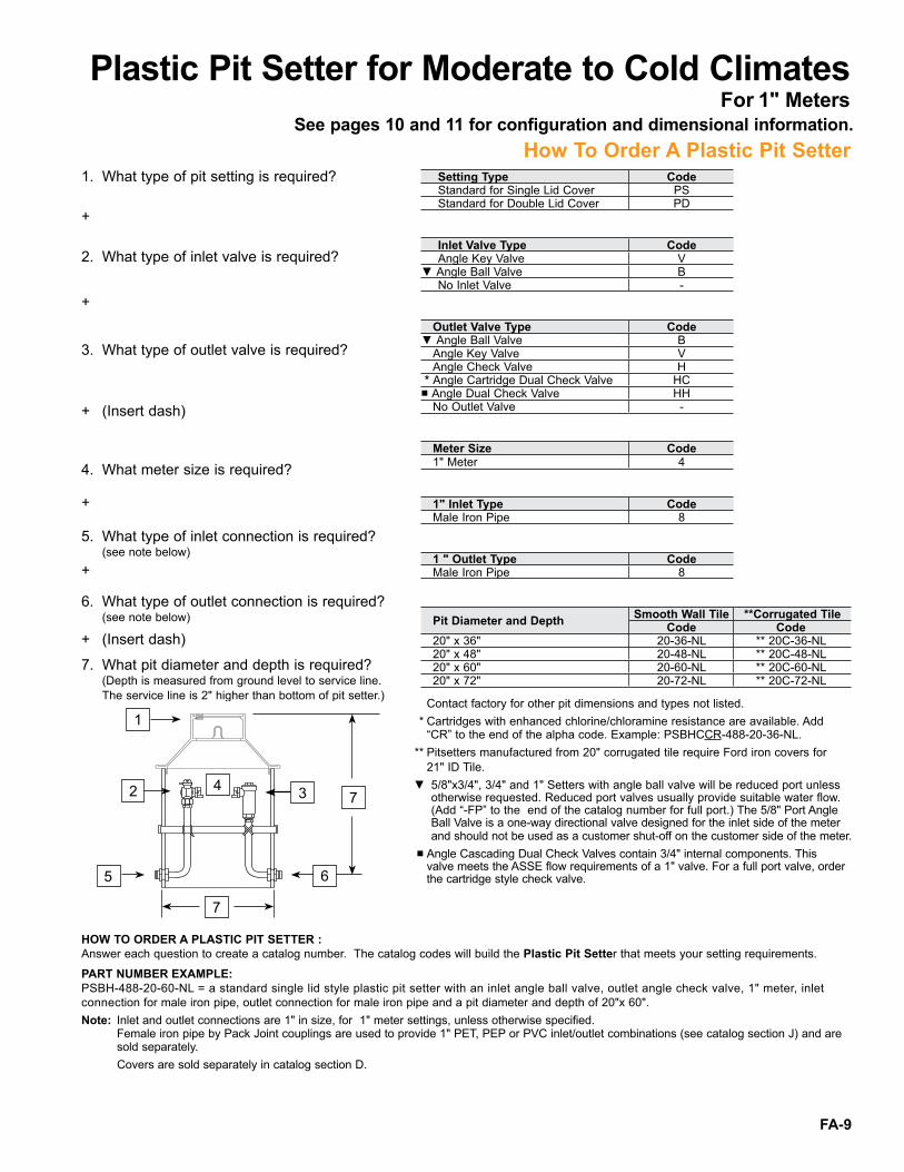
Plastic Pit Setter for Moderate to Cold ClimatesFor 1" Meters
See pages 10 and 11 for configuration and dimensional information.How To Order A Plastic Pit Setter
HOW TO ORDER A PLASTIC PIT SETTER :Answer each question to create a catalog number . The catalog codes will build the Plastic Pit Setter that meets your setting requirements .
PART NUMBER EXAMPLE: PSBH-488-20-60-NL = a standard single lid style plastic pit setter with an inlet angle ball valve, outlet angle check valve, 1" meter, inlet connection for male iron pipe, outlet connection for male iron pipe and a pit diameter and depth of 20"x 60" . Note: Inlet and outlet connections are 1" in size, for 1" meter settings, unless otherwise specified . Female iron pipe by Pack Joint couplings are used to provide 1" PET, PEP or PVC inlet/outlet combinations (see catalog section J) and are sold separately . Covers are sold separately in catalog section D .
Setting Type CodeStandard for Single Lid Cover PSStandard for Double Lid Cover PD
Inlet Valve Type CodeAngle Key Valve V
▼Angle Ball Valve BNo Inlet Valve -
Outlet Valve Type Code▼Angle Ball Valve B
Angle Key Valve VAngle Check Valve H
* Angle Cartridge Dual Check Valve HC■Angle Dual Check Valve HH
No Outlet Valve -
Meter Size Code1" Meter 4
1" Inlet Type CodeMale Iron Pipe 8
1 " Outlet Type CodeMale Iron Pipe 8
Pit Diameter and Depth Smooth Wall Tile **Corrugated Tile
Code Code20" x 36" 20-36-NL ** 20C-36-NL20" x 48" 20-48-NL ** 20C-48-NL20" x 60" 20-60-NL ** 20C-60-NL20" x 72" 20-72-NL ** 20C-72-NL
Contact factory for other pit dimensions and types not listed . * Cartridges with enhanced chlorine/chloramine resistance are available . Add “CR” to the end of the alpha code . Example: PSBHCCR-488-20-36-NL . ** Pitsetters manufactured from 20" corrugated tile require Ford iron covers for 21" ID Tile .▼ 5/8"x3/4", 3/4" and 1" Setters with angle ball valve will be reduced port unless
otherwise requested . Reduced port valves usually provide suitable water flow . (Add “-FP” to the end of the catalog number for full port .) The 5/8" Port Angle Ball Valve is a one-way directional valve designed for the inlet side of the meter and should not be used as a customer shut-off on the customer side of the meter .
■ Angle Cascading Dual Check Valves contain 3/4" internal components . This valve meets the ASSE flow requirements of a 1" valve . For a full port valve, order the cartridge style check valve .
1 . What type of pit setting is required?
2 . What type of inlet valve is required?
3 . What type of outlet valve is required?
+ (Insert dash)
+
4 . What meter size is required?
+
5 . What type of inlet connection is required? (see note below) +
6 . What type of outlet connection is required? (see note below)
+ (Insert dash)
7 . What pit diameter and depth is required? (Depth is measured from ground level to service line . The service line is 2" higher than bottom of pit setter .)
+
1
2
5
3 4
7
7
6

FA-10
Plastic Pit Setter for Moderate to Cold ClimatesFor 5/8", 5/8"x3/4", 3/4" and 1" Meters (Configuration and Dimensional Information)Plastic Pit Setter Design for Single Lid Type (Cover with a 4" depth)
Ford Type “A”, “C”, “X” or “PMBC-3” Single Lid Cover with a 4" depth . (Covers sold separately . See Catalog Section D . A partial list is shown on pages 16 and 17 .)
Dual SettingSingle Meter Setting Tandem Setting
The drawing above shows a Plastic Pit Setter with optional Inlet Angle Ball Valveand Outlet Angle Cartridge Dual Check Valve .
Vertical Measurements<br />
(Pit Diameter is 18" or 20")
Pit Depth
Service<br/>
Line<br/>
Depth<br/>
“A”
PVC<br/>
Cylinder<br/>
Length<br/>
“B”
Total<br/>
Pit<br/>
Depth<br/>
“C”3 Ft . Pit 36" 34" 38"4 Ft . Pit 48" 46" 50"5 Ft . Pit 60" 58" 62"6 Ft . Pit 72" 70" 74"
Ford Angle Ball Valve
FordAngle Cartridge
Dual Check Valve
Inlet
18" or 20"PVC Cylinder
B CA
2" Copper Tube Risers
4"
10"
FA-11
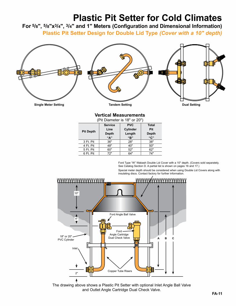
Plastic Pit Setter for Cold ClimatesFor 5/8", 5/8"x3/4", 3/4" and 1" Meters (Configuration and Dimensional Information)
Plastic Pit Setter Design for Double Lid Type (Cover with a 10" depth)
Ford Type “W” Wabash Double Lid Cover with a 10" depth . (Covers sold separately .See Catalog Section D . A partial list is shown on pages 16 and 17 .)Special meter depth should be considered when using Double Lid Covers along with insulating discs . Contact factory for further information .
The drawing above shows a Plastic Pit Setter with optional Inlet Angle Ball Valveand Outlet Angle Cartridge Dual Check Valve .
Vertical Measurements<br/>
(Pit Diameter is 18" or 20")
Pit Depth
Service<br/>
Line<br/>
Depth<br/>
“A”
PVC<br/>
Cylinder<br/>
Length<br/>
“B”
Total<br/>
Pit<br/>
Depth<br/>
“C”3 Ft . Pit 36" 28" 38"4 Ft . Pit 48" 40" 50"5 Ft . Pit 60" 52" 62"6 Ft . Pit 72" 64" 74"
Dual SettingSingle Meter Setting Tandem Setting
Ford Angle Ball Valve
FordAngle Cartridge
Dual Check Valve
Inlet
18" or 20"PVC Cylinder B
10"
CA
2"Copper Tube Risers
4"
FA-12
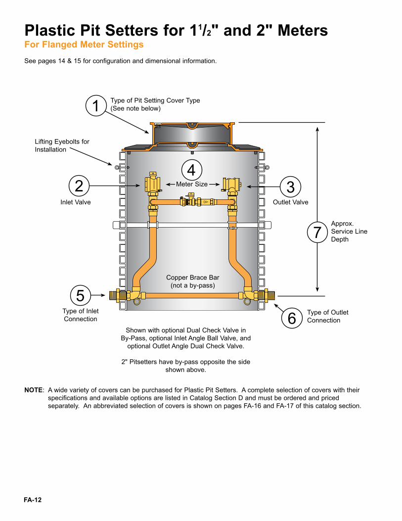
Plastic Pit Setters for 11/2" and 2" MetersFor Flanged Meter Settings
1
2 34
56
7
NOTE: A wide variety of covers can be purchased for Plastic Pit Setters . A complete selection of covers with their specifications and available options are listed in Catalog Section D and must be ordered and priced separately . An abbreviated selection of covers is shown on pages FA-16 and FA-17 of this catalog section .
Lifting Eyebolts for Installation
Inlet Valve Outlet Valve
Approx .Service LineDepth
Meter Size
Copper Brace Bar(not a by-pass)
Type of Inlet Connection
Type of Outlet Connection
Type of Pit Setting Cover Type(See note below)
Shown with optional Dual Check Valve in By-Pass, optional Inlet Angle Ball Valve, and
optional Outlet Angle Dual Check Valve .
2" Pitsetters have by-pass opposite the side shown above .
See pages 14 & 15 for configuration and dimensional information .

FA-13
Plastic Pit Setters for 11/2" and 2" MetersFor Flanged Meter Settings
HOW TO ORDER A PLASTIC PIT SETTER : Answer each question to create a catalog number . The catalog codes will build the Plastic Pit Setter that meets your setting requirements . PART NUMBER EXAMPLE: PMBHH-688-36HB-60-NL = a standard monitor cover style plastic pit setter with an inlet angle ball valve, outlet angle dual check valve, 1-1/2" meter, inlet connection for male iron pipe, outlet connection for male iron pipe, high by-pass and a pit diameter and depth of 36"x 60" . * Meter Flange S-Tube is supplied . Provide PRV length and connection type with order . PRV Adapters are sold separately . ▲ 36" depth not available on 2" Tandem Meter Setters with High By-pass . Note: Inlet and outlet connections are 1-1/2" in size, for 1-1/2" meter settings, 2" for 2" meters . Meter spacing is 13" for 1-1/2" meters and 17" for 2" meters . Female iron pipe by Pack Joint couplings are used to provide PET, PEP or PVC inlet/outlet combinations (see catalog section J) and are sold separately . Extension rings are priced separately in catalog section D .
1-1/2" and 2" Pit Setters are standard with a high by-pass. (2" Pit Setters have the by-pass opposite side from the side shown .) The by-pass can be deleted by omitting the “HB” from the catalog number . Example: PMBHH-688-36-60-NL .
For optional dual cartridge check valve in by-pass, insert “HC” intothe catalog number . Example: PMBHH-688-36HBHC-60-NL .Optional Test Port for dual check 1-1/2" and 2" Pit Setters is available . See catalog section F for more information .
1-1/2" Pit Setter shown with Optional Dual Check Valve in By-Pass
1
2 3 4
7
6
5
Eyebolt for installation
Copper Brace Bar (not a by-pass)
Setting Type CodeStandard for Monitor Cover PMStandard for Single Lid Cover PSStandard for Double Lid Cover PD
* Tandem for Monitor Cover PTM* Tandem for Single Lid Cover PTS* Tandem for Double Lid Cover PTD
Inlet Valve Type CodeAngle Key Valve VAngle Ball Valve B
Outlet Valve Type CodeAngle Ball Valve BAngle Key Valve VAngle Check Valve HAngle Dual Check Valve HHNo Outlet valve (no by-pass) -
Meter Size Code1-1/2" Meter 62" Meter 7
Inlet Type CodeMale Iron Pipe 8
Outlet Type CodeMale Iron Pipe 8
Approx. Pit Diameter and Depth Code▲ 36" x 36" 36HB-36-NL
36" x 42" 36HB-42-NL36" x 48" 36HB-48-NL36" x 54" 36HB-54-NL36" x 60" 36HB-60-NL36" x 66" 36HB-66-NL36" x 72" 36HB-72-NL36" x 78" 36HB-78-NL
1 . What type of pit setting is required?
2 . What type of inlet valve is required?
3 . What type of outlet valve is required?
4 . What meter size is required?
5 . What type of inlet connection is required? (see note below)
6 . What type of outlet connection is required? (see note below)
7 . What pit depth is required? (Depth is measured from ground level to service line . The service line is 4" higher than bottom of pit setter .)
+
+
+ (Insert dash)
+ (Insert dash)
+
+
FA-14
Shown with optional Dual Check Valve in By-Pass, optional Inlet Angle Ball
Valve, and optional Outlet Angle Dual Check Valve .
Copper Brace Bar(not a by-pass)
Plastic Pit Setters for 11/2" and 2" MetersFor Flanged Meter Settings
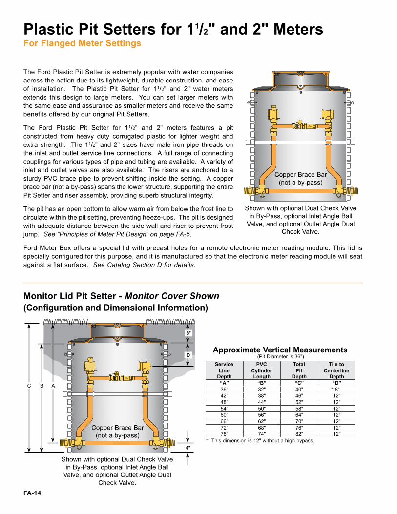
The Ford Plastic Pit Setter is extremely popular with water companies across the nation due to its lightweight, durable construction, and ease of installation . The Plastic Pit Setter for 11/2" and 2" water meters extends this design to large meters . You can set larger meters with the same ease and assurance as smaller meters and receive the same benefits offered by our original Pit Setters .
The Ford Plastic Pit Setter for 11/2" and 2" meters features a pit constructed from heavy duty corrugated plastic for lighter weight and extra strength . The 11/2" and 2" sizes have male iron pipe threads on the inlet and outlet service line connections . A full range of connecting couplings for various types of pipe and tubing are available . A variety of inlet and outlet valves are also available . The risers are anchored to a sturdy PVC brace pipe to prevent shifting inside the setting . A copper brace bar (not a by-pass) spans the lower structure, supporting the entire Pit Setter and riser assembly, providing superb structural integrity .
The pit has an open bottom to allow warm air from below the frost line to circulate within the pit setting, preventing freeze-ups . The pit is designed with adequate distance between the side wall and riser to prevent frost jump . See “Principles of Meter Pit Design” on page FA-5 .
Ford Meter Box offers a special lid with precast holes for a remote electronic meter reading module . This lid is specially configured for this purpose, and it is manufactured so that the electronic meter reading module will seat against a flat surface . See Catalog Section D for details .
Monitor Lid Pit Setter - Monitor Cover Shown(Configuration and Dimensional Information)
Single Lid Pit Setter - Type C Cover<br />
and Extension Ring (EXT-5) Shown<br />
Approximate Vertical Measurements<br />
(Pit Diameter is 36")Service<br />
Line<br />
Depth
PVC<br />
Cylinder<br />
Length
Total<br />
Pit<br />
Depth
Tile to<br />
Centerline<br />
Depth“A” “B” “C” “D”36" 32" 40" **8"42" 38" 46" 12"48" 44" 52" 12"54" 50" 58" 12"60" 56" 64" 12"66" 62" 70" 12"72" 68" 76" 12"78" 74" 82" 12"
** This dimension is 12" without a high bypass .
ABC
4"
8"
D
Copper Brace Bar(not a by-pass)
Shown with optional Dual Check Valve in By-Pass, optional Inlet Angle Ball
Valve, and optional Outlet Angle Dual Check Valve .
FA-15
Plastic Pit Setters for 11/2" and 2" MetersFor Flanged Meter Settings
Shown with optional Dual Check Valve in By-Pass, optional Inlet Angle Ball
Valve, and optional Outlet Angle Dual Check Valve .
Copper Brace Bar(not a by-pass)
Shown with optional Dual Check Valve in By-Pass, optional Inlet Angle Ball
Valve, and optional Outlet Angle Dual Check Valve .
Copper Brace Bar(not a by-pass)
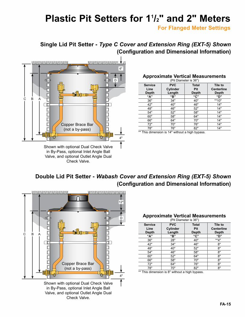
Single Lid Pit Setter - Type C Cover and Extension Ring (EXT-5) Shown(Configuration and Dimensional Information)
Double Lid Pit Setter - Wabash Cover and Extension Ring (EXT-5) Shown (Configuration and Dimensional Information)
Single Lid Pit Setter - Type C Cover<br />
and Extension Ring (EXT-5) Shown<br />
Approximate Vertical Measurements<br />
(Pit Diameter is 36")Service<br />
Line<br />
Depth
PVC<br />
Cylinder<br />
Length
Total<br />
Pit<br />
Depth
Tile to<br />
Centerline<br />
Depth“A” “B” “C” “D”36" 34" 40" **10"42" 40" 46" 14"48" 46" 52" 14"54" 52" 58" 14"60" 58" 64" 14"66" 64" 70" 14"72" 70" 76" 14"78" 76" 82" 14"
** This dimension is 14" without a high bypass .
Double Lid Pit Setter - Wabash Cover<br />
and Extension Ring (EXT-5) Shown<br />
Approximate Vertical Measurements<br />
(Pit Diameter is 36")Service<br />
Line<br />
Depth
PVC<br />
Cylinder<br />
Length
Total<br />
Pit<br />
Depth
Tile to<br />
Centerline<br />
Depth“A” “B” “C” “D”36" 28" 40" **4"42" 34" 46" 8"48" 40" 52" 8"54" 46" 58" 8"60" 52" 64" 8"66" 58" 70" 8"72" 64" 76" 8"78" 70" 82" 8"
** This dimension is 8" without a high bypass .
ABC
4"
6"
D
ABC
4"
12"
D

FA-16
How to Order a Cover Covers for Plastic Pit Setters are sold and listed separately in Ford Catalog Section D . A modest selection of popular covers is listed below . For a complete listing of available lids and covers, along with installation instructions and precautions please refer to Ford Catalog Section D .
Covers with a 10" depth and inset lids - The Wabash Double Lid Cover Inset lids provide an installation that is flush with the surface of the sidewalk or lawn . The inner lid provides greater frost protection for meters . These cast iron covers are 10" in depth and include the lifter Worm Lock with a standard Pentagon Bolt unless a larger bolt is specified .
Covers with a 4" depth and inset lids - The Type A Single Lid Cover Inset lids provide an installation that is flush with the surface of the sidewalk or lawn . These cast iron covers are 4" in depth and include the lifter Worm Lock with a standard Pentagon Bolt unless a larger bolt is specified .
Wabash Double Lid CoversCatalog<br />
NumberDescription Approx.<br />
Wt. Lbs.Lid Size* Tile I.D.Cover with Locking Lid
W2 9-1/2" 18" 42 .0* W32 11-1/2" 18" 50 .0
• * W3 11-1/2" 20" 55 .0Cover with Lockless Lid
W32-LL 11-1/2" 18" 50 .0• W3-LL 11-1/2" 20" 55 .0
Cover with Locking Electronic Meter Read LidW2-T 9-1/2" 18" 42 .0W32-T 11-1/2" 18" 50 .0
• W3-T 11-1/2" 20" 55 .0Cover with Locking Double Electronic Meter Read Lid
W32-TT 11-1/2" 18" 50 .0• W3-TT 11-1/2" 20" 55 .0
Extra Heavy Frame and Extra Heavy Locking Lid• W3H 11-1/2" 20" 89 .0Extra Heavy Frame and Extra Heavy Locking Electronic Meter Read Lid
• W3H-T 11-1/2" 20" 89 .0
Type A Single Lid CoversCatalog<br />
NumberDescription Approx.<br />
Wt. Lbs.Lid Size* Tile I.D.Type A Cover with Locking Lid
A2 9-1/2" 18" 30 .0* A32 11-1/2" 18" 32 .0
• * A3 11-1/2" 20" 37 .0Type A Cover with Lockless Lid
A32-LL 11-1/2" 18" 32 .0• A3-LL 11-1/2" 20" 37 .0
Type A Cover with Locking Electronic Meter Read LidA2-T 9-1/2" 18" 30 .0A32-T 11-1/2" 18" 32 .0
• A3-T 11-1/2" 20" 37 .0Type A Cover with Locking Double Electronic Meter Read LidA32-TT 11-1/2" 18" 32 .0
• A3-TT 11-1/2" 20" 37 .0Extra Heavy Frame and Extra Heavy Locking Lid
• A3H 11-1/2" 20" 54 .0Extra Heavy Frame and Extra Heavy Locking Electronic Meter Read Lid
• A3H-T 11-1/2" 20" 54 .0
* Plastic lid and optional ERT bracket available . See Catalog Section D for more information .• Use with EXT-5 (extension ring) for use on 36" tile applications
* Plastic lid and optional ERT bracket available . See Catalog Section D for more information .• Use with EXT-5 (extension ring) for use on 36" tile applications

FA-17
How to Order a Cover Covers with a 4" depth and overlapping lids - The Type C Single Lid Cover
Overlapping style lid is primarily for installation in lawns . Locking lids have a standard pentagon bolt unless a larger size bolt is specified .
Covers for 1-1/2" and 2" Pit Setters - The Ford Monitor Cover Monitor Covers are designed for use on large tiles where a large lid opening is desired . Each Monitor Cover consists of a flange casting to fit on the tile, a ring, which is centered in place on the flange by a circular bead, and the top lid with a Lifter Worm Lock . An optional plastic inner lid provides added protection against frost damage in cold climates . The Monitor Cover is not designed to withstand traffic, but heavier lids are available for driveway installations where only light traffic is likely .
Cover with a 4" depth and overlapping lid - The Ford PMBC-3 Plastic Meter Box Cover The Ford PMBC-3 plastic meter box cover is an economical alternative to iron covers . Its light weight means reduced shipping costs and easier installation . Constructed of high strength polypropylene, which resists chemical attack and the weakening effect of ultraviolet light, the PMBC-3 fits both 18" and 20" meter pits . As plastic is an excellent insulator, the PMBC-3 provides superior protection against meter pit freeze-ups in all but the harshest climates .
Type C Single Lid Covers Catalog<br />
NumberDescription Approx.<br />
Wt. Lbs.Lid Size* Tile I.D.Cover with Locking Lid
C12 8" 18" 27 .0* C32 11-1/2" 18" 29 .0
C52 15" 18" 39 .0• * C3 11-1/2" 20" 34 .0
Cover with Lockless LidC32-LL 11-1/2" 18" 29 .0
• C3-LL 11-1/2" 20" 34 .0Cover with Locking Electronic Meter Read Lid
C12-T 8" 18" 27 .0C32-T 11-1/2" 18" 29 .0C52-T 15" 18" 39 .0
• C3-T 11-1/2" 20" 34 .0• C53-T 15" 20" 47 .0
Extra Heavy Frame with Extra Heavy with Locking LidC32H 11-1/2" 18" 46 .0
• C3H 11-1/2" 20" 52 .0
PMBC-3 Plastic Meter Box Cover Catalog<br />
NumberDescription Approx.<br />
Wt. Lbs.Lid Size* Tile I.D.Locking lid
• ♦ PMBC-3 11" 18" and 20" 8 .0
Monitor CoversCatalog<br />
NumberDescription Approx.<br />
Wt. Lbs.Lid Size* Tile I.D.Locking Lid
MC-36 20" 36" 185 .0Lockless Lid
MC-36-LL 20" 36" 185 .0Locking Lid with Plastic Inner Lid
MC-36-MB 20" 36" 205 .4Locking Electronic Meter Reading Lid with Plastic Inner Lid
MC-36-MB-T 20" 36" 205 .2
* Lid size indicates pit access opening; lid diameter is approximately 1" larger .♦ Optional ERT bracket add “-BR” to catalog number . Example: PMBC-3-BR• Use with EXT-5 (extension ring) for use on 36" tile applications
* Lid size indicates pit access opening; lid diameter is approximately 1" larger .Smaller lids for 20" I .D . tile will fit 1-1/2" and 2" Pit Setters by using an EXT-5 extension ring, which adapts 20" covers to 36" tile .
* Plastic lid and optional ERT bracket available . See Catalog Section D for more information .• Use with EXT-5 (extension ring) for use on 36" tile applications
FA-18
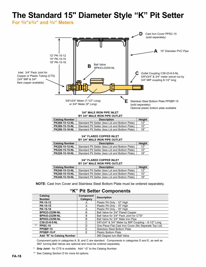
The Standard 15" Diameter Style “K” Pit SetterFor 5/8"x3/4" and 3/4" Meters
A 15" Diameter PVC Pipe
D Cast Iron Cover PPSC-15 (sold separately)
Inlet: 3/4" Pack Joint for Copper or Plastic Tubing (CTS)(3/4" MIP & 3/4" flare copper available)
C Outlet Coupling C38-23-8-5-NL 5/8"x3/4" & 3/4" meter swivel nut by 3/4" MIP coupling 8-1/2" long
B Ball Valve BPK43-232W-NL
12" PK-15-1215" PK-15-1518" PK-15-18
5/8"x3/4" Meter (7-1/2" Long)or 3/4" Meter (9" Long)
E Stainless Steel Bottom Plate PPSBP-15 (sold separately) Optional plastic bottom plate available
NOTE: Cast Iron Cover and Stainless Steel Bottom Plate must be ordered separately .
3/4" MALE IRON PIPE INLET<br />
BY 3/4" MALE IRON PIPE OUTLETCatalog Number Description HeightPK288-15-12-NL Standard Pit Setter (less Lid and Bottom Plate) 12" PK288-15-15-NL Standard Pit Setter (less Lid and Bottom Plate) 15"PK288-15-18-NL Standard Pit Setter (less Lid and Bottom Plate) 18"
3/4" FLARED COPPER INLET<br />
BY 3/4" MALE IRON PIPE OUTLETCatalog Number Description HeightPK228-15-12-NL Standard Pit Setter (less Lid and Bottom Plate) 12"PK228-15-15-NL Standard Pit Setter (less Lid and Bottom Plate) 15" PK228-15-18-NL Standard Pit Setter (less Lid and Bottom Plate) 18"
3/4" FLARED COPPER INLET<br />
BY 3/4" MALE IRON PIPE OUTLETCatalog Number Description HeightPK248-15-12-NL Standard Pit Setter (less Lid and Bottom Plate) 12"PK248-15-15-NL Standard Pit Setter (less Lid and Bottom Plate) 15"PK248-15-18-NL Standard Pit Setter (less Lid and Bottom Plate) 18"
“K” Pit Setter ComponentsCatalog<br />
NumberComponent<br />
Category Description
PK-15-12 A Plastic Pit Only - 12" HighPK-15-15 A Plastic Pit Only - 15" HighPK-15-18 A Plastic Pit Only - 18" HighBPK23-232W-NL B Ball Valve for 3/4" Flared CopperBPK43-232W-NL B Ball Valve for 3/4" Pack Joint for CTS*BPK83-232W-NL B Ball Valve for 3/4" Male Iron PipeC38-23-8-5-NL C 5/8"x3/4" & 3/4" Meter by MIP Coupling – 8-1/2" Long
** PPSC-15 D One Piece Flat Cast Iron Cover (No Separate Top Lid)PPSBP-15 E Stainless Steel Bottom PlatePPSBP-15-P E Plastic Bottom PlateAdd “R” to Catalog Number 360 Degree turn Ball Valve
Component parts in categories A, B, and C are standard . Components in categories D and E, as well as 360° turning Ball Valves are optional and must be ordered separately .<br/>
* Grip Joint - for CTS is available . Add “-G” to the Catalog Number .
** See Catalog Section D for more lid options .

FA-19
The 15" Diameter Style “K” Pit SetterFor Dual 5/8"x3/4" Meter Settings
A 15" Diameter PVC Pipe
D Cast Iron Cover PPSC-15 (sold separately)
C Outlet Couplings (2) C38-23-8-5-NL 5/8"x3/4" meter swivel nut by 3/4" MIP coupling 8-1/2" long
B Branch Valve Assembly with Ball Valves UVBS43-42W-65-NL
12" PKD-15-1215" PKD-15-1518" PKD-15-18
5/8"x3/4" Meter7-1/2" Long
E Stainless Steel Bottom Plate PPSBP-15 (sold separately) Optional plastic bottom plate available
Inlet: 1" Pack Joint for Copper or Plastic Tubing (CTS) (1" MIP & 1" flare copper available)
1" MALE IRON PIPE INLET<br />
BY TWO 3/4" MALE IRON PIPE OUTLETSCatalog Number Description Height
PKD288-15-12-NL Dual Pit Setter (less Lid and Bottom Plate) 12" PKD288-15-15-NL Dual Pit Setter (less Lid and Bottom Plate) 15"PKD288-15-18-NL Dual Pit Setter (less Lid and Bottom Plate) 18"
1" FLARED COPPER INLET<br />
BY TWO 3/4" MALE IRON PIPE OUTLETSCatalog Number Description Height
PKD228-15-12-NL Dual Pit Setter (less Lid and Bottom Plate) 12" PKD228-15-15-NL Dual Pit Setter (less Lid and Bottom Plate) 15"PKD228-15-18-NL Dual Pit Setter (less Lid and Bottom Plate) 18"
1" PACK JOINT FOR COPPER<br /> OR PLASTIC TUBING INLET*BY<br /> TWO 3/4" MALE IRON PIPE OUTLETS
Catalog Number Description HeightPKD248-15-12-NL Dual Pit Setter (less Lid and Bottom Plate) 12" PKD248-15-15-NL Dual Pit Setter (less Lid and Bottom Plate) 15"PKD248-15-18-NL Dual Pit Setter (less Lid and Bottom Plate) 18"
“K” Pit Setter for Dual Meter Setting ComponentsCatalog<br />
NumberComponent<br />
Category Description
PKD-15-12 A Plastic Pit Only - 12" HighPKD-15-15 A Plastic Pit Only - 15" HighPKD-15-18 A Plastic Pit Only - 18" High
UVBS23-42W-65-NL B Branch Valve assembly with Ball Valves<br />
1" Flared Copper to 5/8"x3/4" Meter
UVBS43-42W-65-NL B Branch Valve assembly with Ball Valves <br />
1" Pack Joint for CTS* to 5/8"x3/4" Meter
UVBS83-42W-65-NL B Branch Valve assembly with Ball Valves<br <br /> />
1" Male Iron Pipe to 5/8"x3/4" MeterC38-23-8-5-NL C 5/8"x3/4" Meter by MIP Coupling - 8-1/2" Long
** PPSC-15 D One-Piece Flat Cast Iron Cover (No Separate Top Lid)PPSBP-15 E Stainless Steel Bottom PlatePPSBP-15-P E Plastic Bottom PlateAdd “R” to Catalog Number 360 Degree turn Ball Valve
Component parts in categories A, B, and C are standard . Components in categories D and E, as well as 360° turning Ball Valves are optional and must be ordered separately .<br/>
* Grip Joint - for CTS is available . Add “-G” to the Catalog Number .
** See Catalog Section D for more lid options .

FA-20
The Ford Meter Box Coil Pit Setter design positions the meter below the frost line and allows the meter to be raised to the top of the pit for easy meter access .
Ford Coil Pit Setters and Components are 100% made in the USA
Insulating Foam Disc
Cast Iron Flat Lockless Lid
Driveway Cover(frame and lid)
Insulating disc and lidssold separately
see page 25 for details
The Ford Coil Pit SetterFor 5/8", 5/8"x3/4", 3/4" and 1" Meter Settings
Accessories

FA-21
The Ford Coil Pit SetterFor 5/8", 5/8"x3/4", 3/4" and 1" Meter Settings
STANDARD SPECIFICATIONS 15" Diameter PVC Tile<br />
(.300" Thick)
18" Diameter<br />
PVC Tile<br />
(.360" Thick)SETTING TYPE5/8" Single Setting X X5/8" Tandem Setting X X5/8" Dual Setting X5/8" x 3/4" Single Setting X X5/8" x 3/4" Tandem Setting X X5/8" x 3/4" Dual Setting X3/4" Single Setting X3/4" Tandem Setting X3/4" Dual Setting X*1" Single Setting X*1" Tandem Setting XINLET AND OUTLET SERVICE LINE CONNECTIONS3/4" Coil Tubing with 3/4" MIP X X1" Coil Tubing with 1" MIP inlet with 3/4" MIP outlets & 3/4" tubing (Dual Pits Only) X1" Coil Tubing with 1" MIP (Standard on 1" Setters . Add “A” to all other meter sizes) XCOIL TUBING (HDPE 3408) ASTM D2737 200 PSI3/4" Tubing X X1" Tubing X XADJUSTABLE METER PLATFORM PLATEAll settings X XSUPPORT BRACKETSAll settings X XINSULATION DISC1-1/2" - 6" thickness X XCAST IRON LIDLocking X XLockless X XCast Iron Covers (Standard iron lid will not fit frame) X XCOIL PIT SETTER HEIGHT36" up to 96" X X* 1" Angle Cascading Dual Check Valve contains 3/4" components .
TYPE OF PLASTIC COIL PIT SETTERPFC = Standard Single SettingPDFC = Dual SettingPTFC = Tandem Setting
P F C B H H - 2 8 8 - 1 5 - 7 2 A - F P - N LOUTLET VALVE TYPE
V = Angle Key Valve * B = Angle Ball Valve H = Angle Check Valve HH = Angle Cascading Dual Check Valve** HC = Angle Cartridge Dual Check Valve (on 1" only) L = ELL (No Valve)
METER SIZE(INLET - OUTLET SIZE)
1 = 5/8" (3/4") 2 = 5/8" x 3/4" (3/4") 3 = 3/4" (3/4") 4 = 1" (1") (The number in the parentheses is the standard inlet-outlet size for a given meter size .)
TILE DIAMETER15 = 15" 18 = 18"
INLET VALVE TYPE V = Angle Key Valve*B = Angle Ball Valve
TYPE OF INLET - OUTLET8 = Male Iron Pipe Threads
FULL PORTBALL VALVE
Ford Coil Pit Setter Numbering System
* The 5/8" Port Angle Ball Valve is a one-way directional valve designed for the inlet side of the meter and should not be used as a customer shut-off on the customer side of the meter . 5/8"x3/4", 3/4" & 1" setters with angle ball valves will be reduced port unless otherwise specified . Reduced port valves usually provide suitable water flow . Add “-FP” to end of catalog number for full port .** 1" cartridges with an enhanced chlorine/chloramine resistance are available . Insert “CR” at the end of the alpha code .Example: PFCBHCCR-488-18-60-NL . If PRV lengths are outside of range (see chart on page 22) or have connections other than FNPT . Contact factory for price and availability .
DEPTH36"42"48"54"60"66"72"78"84"90"96"
Optional 1" Tubing and MIP Service Connectionsfor 5/8", 5/8" x 3/4" and 3/4" Setters - NOT AVAILABLE on 15" tiles or dual settings
▲Ford Meter Box no-lead brass products manufactured from UNS/CDA No . 89833 alloy shall contain no more than 0 .25% total lead content by weight . United States federal and state laws allow the use of products manufactured from UNS C83600 85-5-5-5 brass alloy for only non-potable water systems within the United States . Parties responsible for monitoring and maintaining proper water system design must exercise full responsibility in understanding and upholding the full intent and scope of applicable lead laws.
-NL = No-Lead Alloy ▲

FA-22
Dual Setting
18" Diameter Coil Pit Setter with Dual Settings for 5/8", 5/8" x 3/4" or 3/4" Meters
Setting Type Code Dual Setting (flatlidorderedseparately) PDFC
Inlet Valve Type Angle Key Valve V Angle Ball Valve (reduced port) ♦ B**Full Port Angle Ball Valve (see page 23) ♦ B (-FP)
Outlet Valve Type Angle Key Valve V Angle Ball Valve (reduced port) (see page 23) ■ ♦ B** Full Port Angle Ball Valve (see page 23) ♦ B (-FP) Angle Check Valve H Cascading Angle Dual Check Valve (ASSE) HH Ell (no valve) L
Meter Size 5/8" 1 5/8" x 3/4" 2** 3/4" 3
Type of Inlet/Outlet Service Connection1" MIP Inlet/Tubing x (2) 3/4" MIP Outlet/Tubing 88
Pit Diameter and Depth 18" x 42" 18-42-NL 18" x 48" 18-48-NL 18" x 54" 18-54-NL 18" x 60" 18-60-NL 18" x 66" 18-66-NL 18" x 72" 18-72-NL 18" x 78" 18-78-NL 18" x 84" 18-84-NL 18" x 90" 18-90-NL 18" x 96" 18-96-NL
15" Diameter Coil Pit Setter with Single or Tandem Settings for 5/8", or 5/8" x 3/4" Meters
Setting Type Code Standard Coil Pit Setter<br />
(flatlidorderedseparately) PFC Tandem Coil Pit Setter<br />
(flatlidorderedseparately) PTFC
Inlet Valve Type Angle Key Valve V Angle Ball Valve (reduced port) B* Full Port Angle Ball Valve (see page 23) ♦ B (-FP-R)
Outlet Valve Type Angle Key Valve V Angle Ball Valve (reduced port) (see page 23) ■ ♦ B* Full Port Angle Ball Valve (see page 23) ♦ B (-FP-R) Angle Check Valve H Cascading Angle Dual Check Valve (ASSE) HH Ell (no valve) L
Meter Size 5/8" 1 5/8" x 3/4" 2
Type of Inlet/Outlet Service Connection 3/4" MIP x 3/4" MIP with 3/4" tubing 88Pit Diameter and Depth
15" x 36" 15-36-NL 15" x 42" 15-42-NL 15" x 48" 15-48-NL 15" x 54" 15-54-NL 15" x 60" 15-60-NL 15" x 66" 15-66-NL 15" x 72" 15-72-NL 15" x 78" 15-78-NL 15" x 84" 15-84-NL 15" x 90" 15-90-NL 15" x 96" 15-96-NL
Tandem Setting
Single Setting
The Ford Coil Pit SetterFor 5/8", 5/8"x3/4" and 3/4" Meter Settings
Standard Coil Pitsetter PRV Length RangeTile Size and Meter Settings Min Max
5/8" Meter Setting15" Tile 4-1/4" 5-1/4"
15" Tile w/Full port ball valve 3-1/2" 4-1/2"5/8" x 3/4" Meter Setting
15" Tile 4" 4-3/4"15" Tile w/Full port ball valve 3-3/8" 4-1/8"
18" Tile 4-1/2" 5-3/4"18" Tile w/Full port ball valve 3-7/8" 4-7/8"
3/4" Meter Settings18" Tile 4-5/8" 6-5/8"
18" Tile w/Full port ball valve 4-1/8" 6-1/8"1" Meter Settings
18" Tile 4-1/4" 4-1/4"18" Tile w/Full port ball valve 3-1/2" 3-3/4"
PRV lengths with connections other than FNPT or lengths outside of the range; please contact factory for price and availability .
Example: PDFCBHH-288-18-48-NL<br /><br />
Note: Regulator adapters are furnished with standard coil pits . For PRV lengths with end connections other than FNPT or lengths outside of range, see chart below . Contact factory for price and availability .<br /><br />
** Full port ball valves for 3/4" dual setters shall have a 360° rotation . Example: PDFCBHH-388-18-42-FP-R-NL<br /><br />
Custom Coil Pit Setters are available, contact factory.
Example: PFCBHH-288-15-54-NL<br /><br />
Note: Regulator adapters are furnished with standard coil pits . For PRV lengths with end connections other than FNPT or lengths outside of range, see chart below . Contact factory for price and availability .<br /><br />
Coil Pit setters with a ball valve inlet and a ball valve outlet are not recommended on 15" tile, using an 18" tile is advised . The 5/8" port angle ball valve should not be used as a customer shut-off on the customer side of the meter . <br /><br />
*5/8"x3/4" setters with angle ball valves will be reduced port unless otherwise requested . Reduced port valves usually provide suitable waterflow.Add“-FP-R”tothecatalognumberforfullport.Fullportball valves shall have a 360° tee-head rotation . Example: PFCBH-288-15-48-FP-R-NL <br /><br />
All prices are subject to change without notice . Please contact The Ford Meter Box Company .

FA-23
Tandem Setting
18" Diameter Coil Pit Setter with Single or Tandem Settings for 5/8", 5/8" x 3/4", 3/4"
or 1" MetersSetting Type Code
Standard Coil Pit Setter (single) (flatlidorderedseparately) PFC Tandem Coil Pit Setter (flatlidorderedseparately) PTFC
Inlet Valve TypeAngle Key Valve VAngle Ball Valve (reduced port) B
* Full Port Angle Ball Valve (see ♦ below) ♦ B (-FP)Outlet Valve TypeAngle Key Valve VAngle Ball Valve (reduced port) ■ B
* Full Port Angle Ball Valve (see ♦ below) ♦ B (-FP)Angle Check Valve H
Cascading Angle Dual Check Valve (ASSE) ***HH (see below) 1" Cartridge Angle Dual Check Valve (ASSE) HC With enhanced chlorine/chloramine resistant cartridges HCCR Ell (no valve) L
Meter Size 5/8" 1 5/8" x 3/4" 2 3/4" 3** 1" 4
Type of Inlet/Outlet Service Connection 3/4" MIP x 3/4" MIP (for 5/8", 5/8"x3/4", and 3/4" meter settings) with 3/4" tubing ▲88
1" MIP x 1" MIP (for 1" meter settings) with 1" tubing 88Pit Diameter and Depth
18" x 36" 18-36-NL 18" x 42" 18-42-NL 18" x 48" 18-48-NL 18" x 54" 18-54-NL 18" x 60" 18-60-NL 18" x 66" 18-66-NL 18" x 72" 18-72-NL 18" x 78" 18-78-NL 18" x 84" 18-84-NL 18" x 90" 18-90-NL 18" x 96" 18-96-NL
Example: PTFCVHH-488-18-60-NL<br /><br />
* 5/8"x3/4", 3/4" & 1" setters with angle ball valves will be reduced port unless otherwise requested . Reduced port valves usually pro-videsuitablewaterflow.Add“-FP”tothecatalognumberforfullport . Add “-FP-R” where a 360° tee-head rotation is required .
Optional if required Code♦ Optional Full Port Ball Valve
5/8"x3/4", 3/4" & 1" setters with angle ball valves will be reduced port unless otherwise requested . Reduced port valves usually provide suitable water flow . (Add “FP” to the catalog number for full port .) Example: PFCBHH-288-15-48-FP-NL .Add “FP-R” where 360° rotation is required . Example PFCBH-488-18-36-FP-R-NL
-FP
-FP-R
▲ Optional 1" tubing and service line connections are available . Add “A” to the end of the catalog number . Example: PFCBH-288-18-36A-NL . (1" tubing and connections are standard on 1" meters) NOT AVAILABLE on 15" tile or dual settings A
■ The 5/8" Port Angle Ball Valve is a one-way directional valve designed for the inlet side of the meter and should not be used as a customer shut-off on the customer side of the meter .
*** Angle Cascading Dual Check Valves contain 3/4" internal components . This valve meets the ASSE flow requirements of a 1" valve . For a full port valve, order the cartridge style check valve .Optional Covers, Insulating Disc, Frames and Lids: (Order separately) see page 25 .
PitDepth
Lower MountingBracket Height
36" 14"42" 20"48" 26"54" 26"60" 26"66" 26"72" 26"78" 26"84" 26"90" 26"96" 26"2"
PitDepth
LowerMountingBracketHeight
Note: Regulator adapters furnished with Standard Coil Pits, for PRV lengths with end connections other than FNPT or lengths outside range (see chart on page FA-22) contact factory for price and availability .** All Coil Pit Setters for 1" meters must have a 360° tee-head rotation (-R) Example: PTFCBH-488-18-36-R-NL, except for single coil pits with full port ball valves. Example: PFCBH-488-18-36-FP-NL
1" Full Port Single Setting
The Ford Coil Pit SetterFor 5/8", 5/8"x3/4", 3/4"and 1" Meter Settings

FA-24
HOUSING:● SDR 51 PVC PIP tile, per ASTM D2241● Lightweight to provide easy installation● Heights range from 36" to 96"● Bottom is open to allow ground heat from below the frost line to circulate in the pit, preventing freeze-ups● 15" diameter PVC tile ( .300" thick) ● 5/8" and 5/8"x3/4" single meter settings ● 5/8" and 5/8"x3/4" tandem meter settings● 18" diameter PVC tile ( .360" thick) ● 5/8", 5/8"x3/4" and 3/4" single, dual and tandem meter settings ● 1" single and tandem meter settingsCOIL:● Coiled high-density polyethylene (HDPE) tubing, per ASTM D2737, SDR 9 CTS sized● Complies with AWWA C901 (Note: Other comparable products in the market place may use polybutylene coil tubing and claim it meets AWWA C902 Standards . Caution: AWWA has withdrawn Standard C902 and is no longer a valid standard .)● Coil is ANSI/NSF Standard 61 approved● Working pressure 200 PSIG . (This pressure rating should be adequate for any Ford Coil Pit Setter or comparable competitor's product, as some of the connecting valves have a lesser pressure rating .)● Coils are formed by a proprietary process specific to each tile diameter and pit depth, thus allowing consistent mobility while retaining its original form and providing minimal stress to the coil● Ford provides 12" coil extension length standard with each pit to accommodate risers for future grade changesCONNECTIONS:● Brass components that come in contact with potable water conform to AWWA Standard C800 (UNS NO C89833)● Brass components that do not come in contact with potable water conform to AWWA Standard C800 (ASTM B62 and ASTM B584, UNS NO C83600 - 85-5-5-5)● Inlet and outlet service line connections are MIP and are clearly labeled● Angled 60° elbows provide minimal stress on the tubing and maintain proper coil orientation● Quick Joint Nuts (QJN) with thin stainless steel inserts are used for connecting to the HDPE tubing allowing full water flow, unlike crimping techniques requiring a thick brass insert that reduces the tubing ID at every connection● Special lubricants within the QJN allow it to rotate on the tubing without becoming loose or compromising the connection● If ever necessary, removal of coil or replacement of connections is easy and inexpensive as it only requires replacing the QJN gasket, unlike crimping techniques that require special tools, complete replacement of tubing and the entire crimped connectionMETER MOUNTING PLATFORMS:● Single or tandem platforms are molded polypropylene with structural ribs for rigidity● Dual setting platforms are made from e-coated aluminum● Various product heights may require spacers for alignment purposes
PLATFORM ACCESS RODS (ordered separately):● Carbon Steel wire ASTM A510 with black e-coat finish● Constructed with opposing fingers that fit over meter and hook under meter spuds which securely holds platform and meter during vertical movement● Reduces potential tube drag by allowing a counterclockwise movement of the meter assembly that slightly tightens coil, reducing coil diameter● Available 36" up to 72" long
EXTENSION RINGS (ordered separately):● SDR 51 PVC PIP tile, per ASTM D2241● Available in 2" increments up to 12" . (Coil pits are standard with an extra 12" of tubing to accommodate up to 12" extension)● Three separate locating supports● Support/lid bracket factory installed
BOTTOM PLATES:● Available as stainless steel partial tile bottom for 15" (15 .30 O .D .) and 18" (18 .70 O .D .) heavy walled PVC● Available as plastic solid bottom for 15" (15 .30 O .D .) and 18" (18 .70 O .D .) heavy walled PVC● Drain holes may be field installed in solid pit bottom or at factoryBRASS VALVES:● Brass components that come in contact with potable water conform to AWWA Standard C800 (UNS NO C89833)● Brass components that do not come in contact with potable water conform to AWWA Standard C800 (ASTM B62 and ASTM B584, UNS NO C83600 - 85-5-5-5)● All dual check valves are ASSE 1024 approved● 1" full port ball valve settings shall have the ball valve rotated and a 120° elbow will be assembled to maintain meter alignment within the tile ID . 5/8", 5/8" x 3/4" . 3/4" and 1" Coil Pit Setters with angle ball valves will be reduced port unless otherwise specified . Add “-FP” to the catalog number for full port .● Brass valves and fittings will maintain their individual NSF/ ANSI Standard 61 Approval where applicableIRON LIDS (Order separately):● Locking and lockless lids are cast iron, per ASTM A48, Class 25● Available with single or double 2" EMR holes● Optional under-the-lid AMR plastic mounting plate● Not for use with Coil Pit Driveway Covers below
IRON DRIVEWAY COVERS (Order separately):● Load rating of 25,000 pounds● Standard Ford worm latch with Pentagon Bolt● Mounting wide cast lugs used in place of mounting bracket● Available with electronic meter read feature (2" hole), -T or -TT● Not for use with standard coil pit flat iron lidINSULATING DISC (Order separately):● 1-1/2" - 6" thick, minimum R-value 6 .0 - 12 .0● Closed-cell polyethylene foam resists moisture absorption● Provides extra protection against meter freeze-ups● Plastic tie strap handle to assist in disc removal
The Ford Coil Pit SetterFeatures

FA-25
Cast Iron Flat LidsCatalog Number Size Approx. Wt Catalog Number Size Approx. Wt.
Lockless LidsPPSC-15 15" 20 .0 PPSC-18 18" 28 .0
Locking LidsPPSC-15-L 15" 20 .0 PPSC-18-L 18" 28 .0
Locking Lids with Plastic ERT BracketPPSC-15-L-BR 15" 20 .0 PPSC-18-L-BR 18" 28 .0
Locking Electronic Read LidPPSC-15-L-T 15" 20 .0 PPSC-18-L-T 18" 28 .0
Locking Double Electronic Read LidPPSC-15-L-TT 15" 20 .0 PPSC-18-L-TT 18" 28 .0
Recessed Locking Electronic Read LidPPSC-15-L REC-T 15" 20 .0 PPSC-18-L-REC-T 18" 28 .0
Lockless Reading Lid- - - PPSC-18-OS-RL 18" 28 .0
Lockless Electronic Read LidPPSC-15-T 15" 20 .0 PPSC-18-T 18" 28 .0
Double Lockless Electronic Read LidPPSC-15-TT 15" 20 .0 PPSC-18-TT 18" 28 .0
Recessed Lockless Electronic Read LidPPSC-15-REC-T 15" 17 .2 - - -
Recessed Lockless Electronic Read Lid (Extra Heavy)PPSCH-15-REC-T 15" 40 .5 - - -
H-20 Rated Composite Flat LidsLocking Lids
PPSC-15-L-P 15" 18 .5 PPSC-18-L-P 18" 27 .0Locking Lids with Plastic ERT Bracket
PPSC-15-L-P-BR 15" 18 .8 PPSC-18-L-P-BR 18" 27 .3
Coil Pit Iron Driveway Cover (Frame and Lid)Catalog Number Description and Size Approx. Wt
Cover (Frame and Locking Lid)A51H 15" 65 .0A62H 18" 74 .0
Cover (Frame with Electronic Read Locking Lid)A51H-T 15" 65 .0A62H-T 18" 74 .0
Cover (Frame with Double Electronic Read Locking Lid)
A51H-TT 15" 65 .0A62H-TT 18" 74 .0Cover (Frame with Recessed Electronic Read
Lockless Lid (Extra Heavy))A51H-LL-REC-T 15" 70 .0
Iron Frame Only*PFC15F 15" 30 .0*PFC18F 18" 39 .0
Locking Lid OnlyWA5LH 15" 35 .0WA6LH 18" 35 .0
Locking Electronic Read Lid OnlyWA5LH-T 15" 35 .0WA6LH-T 18" 35 .0
Locking Double Electronic Read Lid OnlyWA5LH-TT 15" 35 .0WA6LH-TT 18" 35 .0
Closed Cell Insulating DiscsCatalog Number Meter Pit
Diameter Thickness MinimumR-Value Color
CCID-1515"
1-1/2" 6 .0 GrayCCID-15-2 2" 4 .0 Green or WhiteCCID-15-4 4" 8 .0 Green or WhiteCCID-15-6 6" 12 .0 Green or WhiteCCID-18
18"
1-1/2" 6 .0 GrayCCID-18-2 2" 4 .0 Green or WhiteCCID-18-4 4" 8 .0 Green or WhiteCCID-18-6 6" 12 .0 Green or White
Special meter depth may be required on meter pits depending on lid type and disc thickness . Contact factory for further information .
The Ford Coil Pit SetterOptional Items Ordered Separately
Coil Pit Lids and Bottom Plates
*Framescannotbeusedwithstandardcoilpitflatlids,mustbe used with these matching lids only .These covers carry a 25,000 pound load rating .

FA-26
The Ford Coil Pit SetterOptional Items Ordered SeparatelyCoil Pit Access Rods and Extension RIngs
Coil Pit Meter Platform Access RodsCatalog Number Meter Size Service Line
Depth Approx. Wt.
CPLR-2-36 5/8" or 5/8" x 3/4" Up to 60" 5 .0CPLR-2-48 5/8" or 5/8" x 3/4" Up to 72" 6 .0CPLR-2-60 5/8" or 5/8" x 3/4" Up to 84" 7 .0CPLR-2-72 5/8" or 5/8" x 3/4" Up to 96" 8 .0CPLR-3-36 3/4" Up to 60" 5 .0CPLR-3-48 3/4" Up to 72" 6 .0CPLR-3-60 3/4" Up to 84" 7 .0CPLR-3-72 3/4" Up to 96" 8 .0CPLR-4-36 1" Up to 60" 5 .0CPLR-4-48 1" Up to 72" 6 .0CPLR-4-60 1" Up to 84" 7 .0CPLR-4-72 1" Up to 96" 8 .0
Coil Pit Extension RingsExtension
Length15" Diameter
TileApprox.
Wt.18" Diameter
Tile Approx. Wt.
2" CPS-EXT15-2 1 .7 CPS-EXT18-2 2 .54" CPS-EXT15-4 3 .3 CPS-EXT18-4 4 .86" CPS-EXT15-6 4 .9 CPS-EXT18-6 7 .28" CPS-EXT15-8 6 .5 CPS-EXT18-8 9 .610" CPS-EXT15-10 8 .2 CPS-EXT18-10 12 .012" CPS-EXT15-12 9 .6 CPS-EXT18-12 14 .3
Stainless Steel Bottom PlateCatalogNumber Size Approx.
Wt.CatalogNumber Size Approx. Wt.
PPSBP-15 15 .3" 3 .3 *PPSBP-18H 18 .7" 3 .9
Solid Plastic Bottom PlateCatalogNumber Size Approx.
Wt.CatalogNumber Size Approx. Wt.
PPSBP-15-P 15 .3" 1 .0 *PPSBP-18H-P 18 .7" 2 .0
Rods are sold by meter pit size and service line depth .
Standard Coil Pits can accommodate up to a maximum 12" extension ring . Extension lengths are in 2" increments from 2" to 12" for each tile diameter .
* For use on all coil pit setters and pit setters with heavy wall tile .
* For use on all coil pit setters and pit setters with heavy wall tile .

FA-27
INSTALLATION INSTRUCTIONSFOR THE FORD COIL PIT SETTER
1 . Dig trench to proper depth for Coil Pit Setter and lid, also allow for bottom support/drainage .
2 . Place crushed gravel or an even layer of concrete blocks in the bottom of hole; if using a bottom plate, place in hole before installing the Coil Pit Setter .
3 . Lower the pit setter in the hole so that the top edge isflushwithgradelevel.
4 . Connect the inlet and outlet service lines to the appropriate connection as marked on the tile by placinganadditionalwrenchonthewrenchflatsoftheMIPfittingtoavoidunintentionaltwistingofthecoil tubing .
5 . PressuretesttheCoilPitSetterpriortobackfillingtoensure all valves and joints are secured tightly and no leaks are detected .
6 . IMPORTANT:Carefullybackfillaroundthetile,12"at a time, tamping each layer. Improper backfillmay distort tile, resulting in immobility of the meter mounting platform .
PRECAUTIONS1 . Do not kink, fold, or over-stress the coil tube or
damage may result . Avoid cuts, nicks and abrasions to the coil tube as they may affect service life and pressure integrity . Damaged coils should be replaced .
2 . Be sure to lift the meter mounting platform just past both locking brackets . Rest the platform on the locking brackets and engage securing the notch of the platform onto one of the locking brackets . This secures the assembly while servicing the meter .
3 . Ford’sflatlidshouldbeplacedproperlyonthetileafter each entry . Locking lid should have the lug and locking mechanism aligned within the tile’s locking brackets to secure lock .
4 . Meter mounting platform should be completely lowered to the lower support bracket when meter is not being serviced .
5 . Store Coil Pit Setter in upright position, do not stack on its side .
LockingBracket
WrenchFlats
MIPThreads
Ford Flat lid (PPSC)
(sold separately)
InsulatingDisc (CCID)
(sold separately)
MeterMountingPlatform
ClearanceNotch
LowerSupport Bracket
SecuringNotch
The Ford Coil Pit SetterInstallation Instructions

Parties responsible for monitoring and maintaining proper water system design must exercise full responsibility in understanding and upholding the full intent and scope of applicable lead laws.
Please Note:Consult The Ford Meter Box Company, Inc . website (www .fordmeterbox .com) for the most recent catalog information . The Ford Meter Box Company considers the information in this catalog to be correct at the time of publication . Items and option availability, including specifications, are subject to change without notice . Please verify that your product information is current .
Warranty All merchandise is warranted to be free from defects in material and factory workmanship for one year from date of shipment from our factory . We will provide, free of charge, new products in equal quantities for any that prove defective within one year from date of shipment from our factory . Manufacturer shall not be liable for any loss, damage, or injury, direct or consequential, arising out of the use of or the inability to use the product . Before using, user shall determine the suitability of the product for user’s intended use and user assumes all risk and liability whatever in connection therewith . No claims for labor or consequential damage will be allowed . The foregoing may not be changed except by agreement signed by an officer of the manufacturer .
No other warranties are applicable or may be implied, including the implied warranty of merchantability and the implied warranty of fitness for particular purpose and any warranty relating to infringement or the like, all of which are disclaimed .
Section FAFordPlastic PitSetters
The Ford Meter Box Co., Inc. 775 Manchester Avenue, P .O . Box 443, Wabash, Indiana, USA 46992-0443Telephone: 260/563-3171 FAX: 1-800-826-3487 Overseas FAX: 260/563-0167 www .fordmeterbox .com
02/2015 - 7 .5M New Image Printing and Design