ford, lincoln, mercury 2004-2010 wiring & antenna ... · ford, lincoln, mercury 2004-2010 (see...
TRANSCRIPT
METRA. The World’s best kits.® metraonline.com © COPYRIGHT 2017 METRA ELECTRONICS CORPORATION
REV.
11/
17/2
017
INS
T99-
5807
Installation instructions for part 99-5807
®
CAUTION! Metra recommends disconnecting the negative bat-tery terminal before beginning any installation, unless the vehicle manufacturer recommends against so. Please check with your local Dealership for more information. All accessories, switches, climate controls panels, and especially air bag indicator lights must be con-nected before reconnecting the battery or cycling the ignition. Also, do not remove the factory radio with the key in the on position, or the vehicle running. It would be best to remove the key from the ignition and then wait a few seconds before removing the factory radio.
U.S. PATENT # D504,423
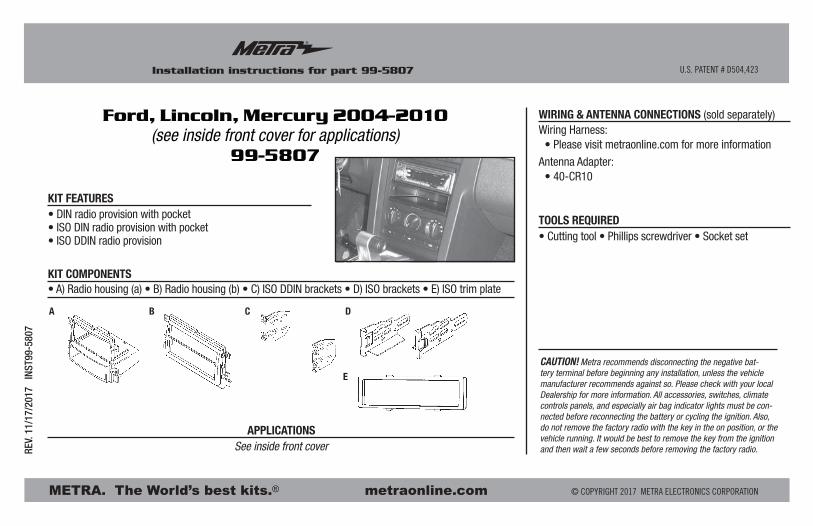
• DIN radio provision with pocket• ISO DIN radio provision with pocket• ISO DDIN radio provision
• A) Radio housing (a) • B) Radio housing (b) • C) ISO DDIN brackets • D) ISO brackets • E) ISO trim plate
KIT FEATURES
KIT COMPONENTS
WIRING & ANTENNA CONNECTIONS (sold separately)Wiring Harness: • Please visit metraonline.com for more information
Antenna Adapter: • 40-CR10
See inside front cover
• Cutting tool • Phillips screwdriver • Socket set
APPLICATIONS
TOOLS REQUIRED
Ford, Lincoln, Mercury 2004-2010(see inside front cover for applications)
99-5807
A B C D
E
99-5807
®
2
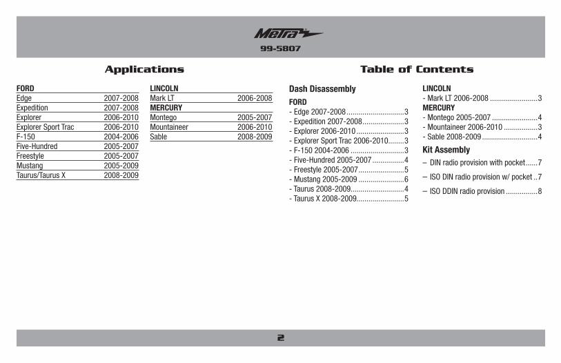
Table of Contents
Dash DisassemblyFORD- Edge 2007-2008 .............................3- Expedition 2007-2008 .....................3- Explorer 2006-2010 ........................3- Explorer Sport Trac 2006-2010........3- F-150 2004-2006 ...........................3- Five-Hundred 2005-2007 ................4- Freestyle 2005-2007 .......................5- Mustang 2005-2009 .......................6- Taurus 2008-2009...........................4 - Taurus X 2008-2009........................5
LINCOLN- Mark LT 2006-2008 ........................3MERCURY- Montego 2005-2007 .......................4- Mountaineer 2006-2010 .................3- Sable 2008-2009 ............................4
Kit Assembly– DIN radio provision with pocket ......7
– ISO DIN radio provision w/ pocket ..7
– ISO DDIN radio provision ................8
Applications
FORDEdge 2007-2008Expedition 2007-2008Explorer 2006-2010Explorer Sport Trac 2006-2010F-150 2004-2006Five-Hundred 2005-2007Freestyle 2005-2007Mustang 2005-2009Taurus/Taurus X 2008-2009
LINCOLNMark LT 2006-2008MERCURYMontego 2005-2007Mountaineer 2006-2010Sable 2008-2009
99-5807
®
(Figure A)
(Figure B)
(Figure C)
Dash Disassembly
(Figure A)
(Figure B)
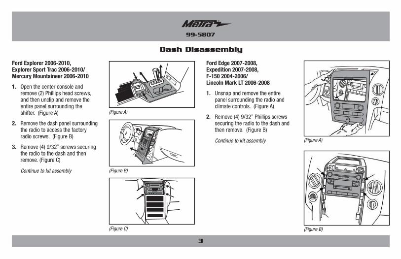
Ford Edge 2007-2008, Expedition 2007-2008, F-150 2004-2006/ Lincoln Mark LT 2006-2008
1. Unsnap and remove the entire panel surrounding the radio and climate controls. (Figure A)
2. Remove (4) 9/32” Phillips screws securing the radio to the dash and then remove. (Figure B)
Continue to kit assembly
3
Ford Explorer 2006-2010, Explorer Sport Trac 2006-2010/ Mercury Mountaineer 2006-2010
1. Open the center console and remove (2) Phillips head screws, and then unclip and remove the entire panel surrounding the shifter. (Figure A)
2. Remove the dash panel surrounding the radio to access the factory radio screws. (Figure B)
3. Remove (4) 9/32” screws securing the radio to the dash and then remove. (Figure C)
Continue to kit assembly
99-5807
®
Dash Disassembly
(Figure E)
(Figure D)
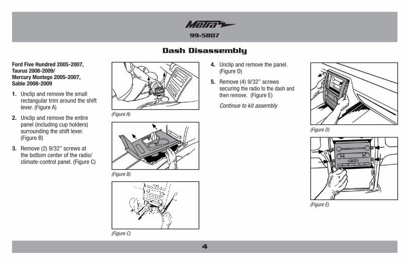
Ford Five Hundred 2005-2007, Taurus 2008-2009/ Mercury Montego 2005-2007, Sable 2008-2009
1. Unclip and remove the small rectangular trim around the shift lever. (Figure A)
2. Unclip and remove the entire panel (including cup holders) surrounding the shift lever. (Figure B)
3. Remove (2) 9/32” screws at the bottom center of the radio/climate-control panel. (Figure C)
4. Unclip and remove the panel. (Figure D)
5. Remove (4) 9/32” screws securing the radio to the dash and then remove. (Figure E)
Continue to kit assembly(Figure A)
(Figure B)
(Figure C)
4
99-5807
®
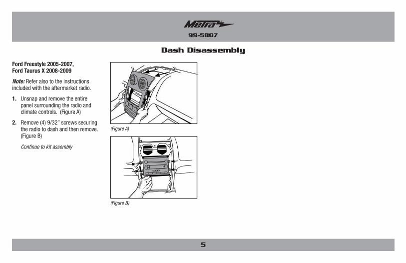
Ford Freestyle 2005-2007, Ford Taurus X 2008-2009
Note: Refer also to the instructions included with the aftermarket radio.
1. Unsnap and remove the entire panel surrounding the radio and climate controls. (Figure A)
2. Remove (4) 9/32” screws securing the radio to dash and then remove. (Figure B)
Continue to kit assembly
Dash Disassembly
(Figure B)
(Figure A)
5
99-5807
®
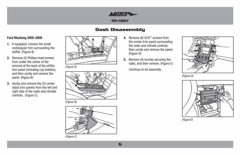
Ford Mustang 2005-2009
1. If equipped, remove the small rectangular trim surrounding the shifter. (Figure A)
2. Remove (2) Phillips head screws from under the center of the armrest at the back of the shifter trim panel (including cup holders), and then unclip and remove the panel. (Figure B)
3. Unclip and remove the (2) center stack trim panels from the left and right side of the radio and climate controls. (Figure C)
4. Remove (6) 9/32” screws from the center trim panel surrounding the radio and climate controls, then unclip and remove the panel. (Figure D)
5. Remove (4) screws securing the radio, and then remove. (Figure E)
Continue to kit assembly
Dash Disassembly
(Figure E)
(Figure D)
(Figure A)
(Figure B)
(Figure C)
6
99-5807
®
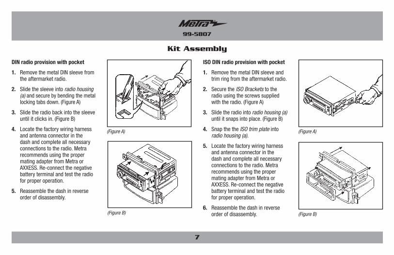
ISO DIN radio provision with pocket
1. Remove the metal DIN sleeve and trim ring from the aftermarket radio.
2. Secure the ISO Brackets to the radio using the screws supplied with the radio. (Figure A)
3. Slide the radio into radio housing (a) until it snaps into place. (Figure B)
4. Snap the the ISO trim plate into radio housing (a).
5. Locate the factory wiring harness and antenna connector in the dash and complete all necessary connections to the radio. Metra recommends using the proper mating adapter from Metra or AXXESS. Re-connect the negative battery terminal and test the radio for proper operation.
6. Reassemble the dash in reverse order of disassembly. (Figure B)
(Figure A)
Kit Assembly
DIN radio provision with pocket
1. Remove the metal DIN sleeve from the aftermarket radio.
2. Slide the sleeve into radio housing (a) and secure by bending the metal locking tabs down. (Figure A)
3. Slide the radio back into the sleeve until it clicks in. (Figure B)
4. Locate the factory wiring harness and antenna connector in the dash and complete all necessary connections to the radio. Metra recommends using the proper mating adapter from Metra or AXXESS. Re-connect the negative battery terminal and test the radio for proper operation.
5. Reassemble the dash in reverse order of disassembly.
(Figure B)
(Figure A)
7
METRA. The World’s best kits.® metraonline.com © COPYRIGHT 2017 METRA ELECTRONICS CORPORATION
REV.
11/
17/2
017
INS
T99-
5807
KNOWLEDGE IS POWEREnhance your installation and fabrication skills by enrolling in the most recognized and respected mobile electronics school in our industry.Log onto www.installerinstitute.com or call 800-354-6782 for more information and take steps toward a better tomorrow.
®
Metra recommends MECP certified technicians
Installation instructions for part 99-5807Installation instructions for part 99-5807
®
IMPORTANTIf you are having difficulties with the installation of this product, please call our Tech Support line at 1-800-253-TECH. Before doing so, look over the instructions a second time, and make sure the installation was performed exactly as the instructions are stated. Please have the vehicle apart and ready to perform troubleshooting steps before calling.
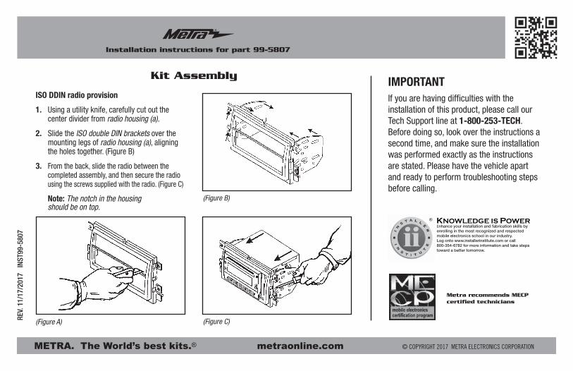
ISO DDIN radio provision
1. Using a utility knife, carefully cut out the center divider from radio housing (a).
2. Slide the ISO double DIN brackets over the mounting legs of radio housing (a), aligning the holes together. (Figure B)
3. From the back, slide the radio between the completed assembly, and then secure the radio using the screws supplied with the radio. (Figure C)
Note: The notch in the housing should be on top.
(Figure B)
(Figure C)(Figure A)
Kit Assembly
METRA. The World’s best kits.® metraonline.com © COPYRIGHT 2017 METRA ELECTRONICS CORPORATION
REV.
11/
17/2
017
INS
T99-
5807
Instrucciones de instalación para la pieza 99-5807
®
¡PRECAUCIÓN! Meta recomienda desconectar la terminal negativa de la batería antes de iniciar cualquier instalación, a menos que el fabricante del vehículo recomiende lo contrario. Verifique con su concesionario local si existe más información. Todos los accesorios, interruptores, paneles de controles de clima y especialmente las lu-ces del indicador de las bolsas de aire deben estar conectados antes de reconectar la batería o ciclar la ignición. Además, no quite el radio de fábrica con la llave en la posición de encendido ni con el vehículo funcionando. Sería mejor retirar la llave de la ignición y esperar unos cuantos segundos antes de quitar el radio de fábrica.
U.S. PATENT # D504,423
• Provisión de radio DIN con cavidad• Provisión de radio ISO DIN con cavidad• Provisión de radio ISO DDIN
• A) Carcasa del radio (a) • B) Carcasa del radio (b) • C) Soportes ISO DDIN • D) Soportes ISO • E) Placa de moldura ISO
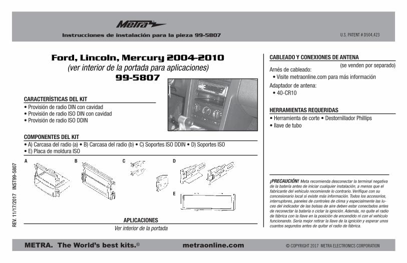
CARACTERÍSTICAS DEL KIT
COMPONENTES DEL KIT
CABLEADO Y CONEXIONES DE ANTENA (se venden por separado)Arnés de cableado: • Visite metraonline.com para más información
Adaptador de antena: • 40-CR10
Ver interior de la portada
• Herramienta de corte • Destornillador Phillips• llave de tubo
APLICACIONES
HERRAMIENTAS REQUERIDAS
Ford, Lincoln, Mercury 2004-2010(ver interior de la portada para aplicaciones)
99-5807
A B C D
E
99-5807
®
2
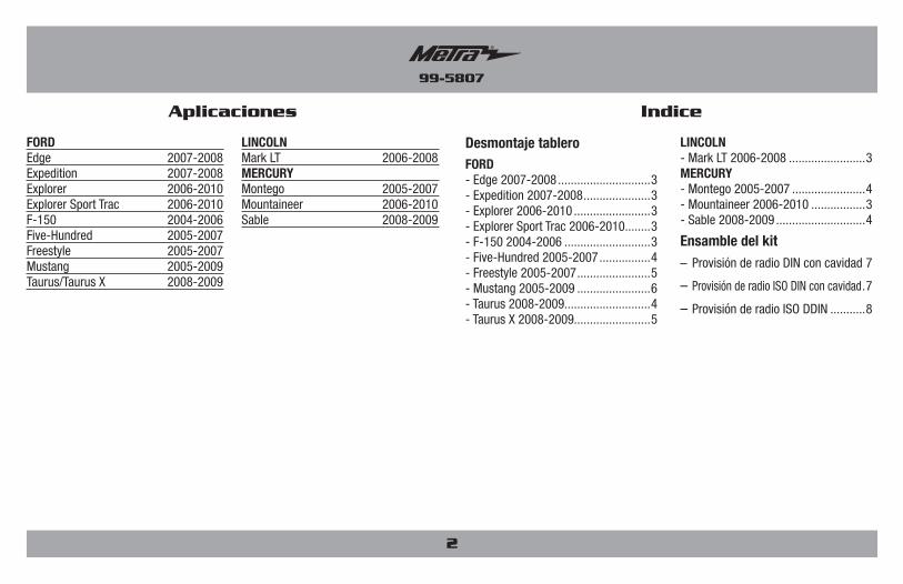
Indice
Desmontaje tableroFORD- Edge 2007-2008 .............................3- Expedition 2007-2008 .....................3- Explorer 2006-2010 ........................3- Explorer Sport Trac 2006-2010........3- F-150 2004-2006 ...........................3- Five-Hundred 2005-2007 ................4- Freestyle 2005-2007 .......................5- Mustang 2005-2009 .......................6- Taurus 2008-2009...........................4 - Taurus X 2008-2009........................5
LINCOLN- Mark LT 2006-2008 ........................3MERCURY- Montego 2005-2007 .......................4- Mountaineer 2006-2010 .................3- Sable 2008-2009 ............................4
Ensamble del kit– Provisión de radio DIN con cavidad 7
– Provisión de radio ISO DIN con cavidad .7
– Provisión de radio ISO DDIN ...........8
Aplicaciones
FORDEdge 2007-2008Expedition 2007-2008Explorer 2006-2010Explorer Sport Trac 2006-2010F-150 2004-2006Five-Hundred 2005-2007Freestyle 2005-2007Mustang 2005-2009Taurus/Taurus X 2008-2009
LINCOLNMark LT 2006-2008MERCURYMontego 2005-2007Mountaineer 2006-2010Sable 2008-2009
99-5807
®
(Figura A)
(Figura B)
(Figura C)
Desmontaje tablero
(Figura A)
(Figura B)
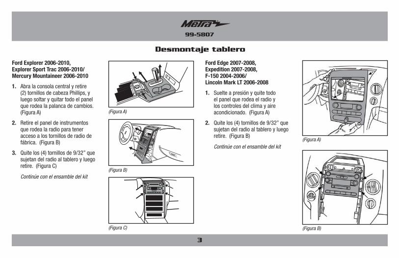
Ford Edge 2007-2008, Expedition 2007-2008, F-150 2004-2006/ Lincoln Mark LT 2006-2008
1. Suelte a presión y quite todo el panel que rodea el radio y los controles del clima y aire acondicionado. (Figura A)
2. Quite los (4) tornillos de 9/32” que sujetan del radio al tablero y luego retire. (Figura B)
Continúe con el ensamble del kit
3
Ford Explorer 2006-2010, Explorer Sport Trac 2006-2010/ Mercury Mountaineer 2006-2010
1. Abra la consola central y retire (2) tornillos de cabeza Phillips, y luego soltar y quitar todo el panel que rodea la palanca de cambios. (Figura A)
2. Retire el panel de instrumentos que rodea la radio para tener acceso a los tornillos de radio de fábrica. (Figura B)
3. Quite los (4) tornillos de 9/32” que sujetan del radio al tablero y luego retire. (Figura C)
Continúe con el ensamble del kit
99-5807
®
Desmontaje tablero
(Figura E)
(Figura D)
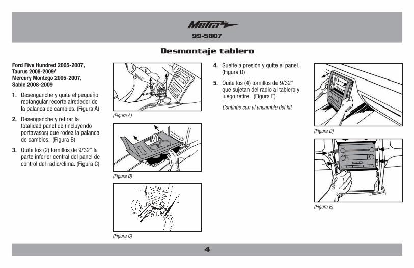
Ford Five Hundred 2005-2007, Taurus 2008-2009/ Mercury Montego 2005-2007, Sable 2008-2009
1. Desenganche y quite el pequeño rectangular recorte alrededor de la palanca de cambios. (Figura A)
2. Desenganche y retirar la totalidad panel de (incluyendo portavasos) que rodea la palanca de cambios. (Figura B)
3. Quite los (2) tornillos de 9/32” la parte inferior central del panel de control del radio/clima. (Figura C)
4. Suelte a presión y quite el panel. (Figura D)
5. Quite los (4) tornillos de 9/32” que sujetan del radio al tablero y luego retire. (Figura E)
Continúe con el ensamble del kit(Figura A)
(Figura B)
(Figura C)
4
99-5807
®
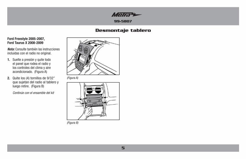
Ford Freestyle 2005-2007, Ford Taurus X 2008-2009
Nota: Consulte también las instrucciones incluidas con el radio no original.
1. Suelte a presión y quite todo el panel que rodea el radio y los controles del clima y aire acondicionado. (Figura A)
2. Quite los (4) tornillos de 9/32” que sujetan del radio al tablero y luego retire. (Figura B)
Continúe con el ensamble del kit
Desmontaje tablero
(Figura B)
(Figura A)
5
99-5807
®
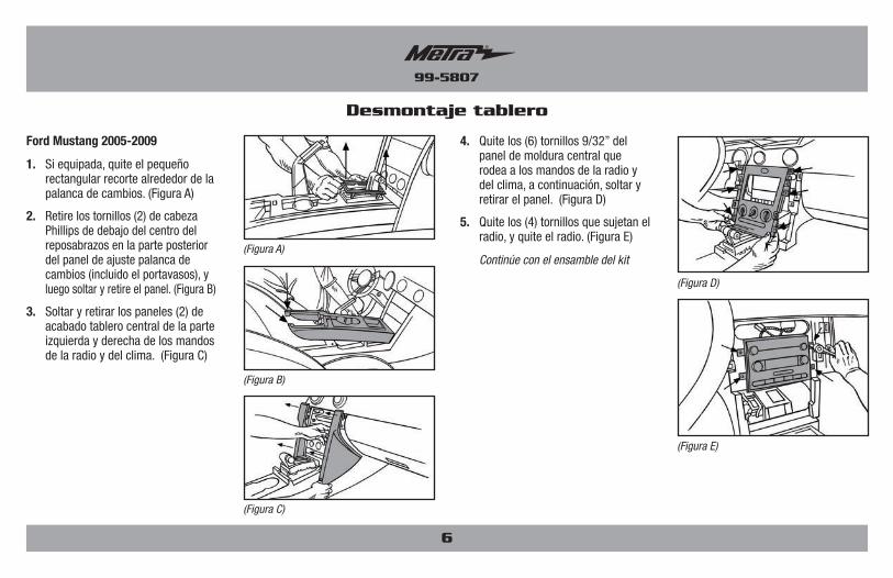
Ford Mustang 2005-2009
1. Si equipada, quite el pequeño rectangular recorte alrededor de la palanca de cambios. (Figura A)
2. Retire los tornillos (2) de cabeza Phillips de debajo del centro del reposabrazos en la parte posterior del panel de ajuste palanca de cambios (incluido el portavasos), y luego soltar y retire el panel. (Figura B)
3. Soltar y retirar los paneles (2) de acabado tablero central de la parte izquierda y derecha de los mandos de la radio y del clima. (Figura C)
4. Quite los (6) tornillos 9/32” del panel de moldura central que rodea a los mandos de la radio y del clima, a continuación, soltar y retirar el panel. (Figura D)
5. Quite los (4) tornillos que sujetan el radio, y quite el radio. (Figura E)
Continúe con el ensamble del kit
Desmontaje tablero
(Figura E)
(Figura D)
(Figura A)
(Figura B)
(Figura C)
6
99-5807
®
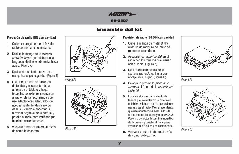
Provisión de radio ISO DIN con cavidad
1. Quite la manga de metal DIN y el anillo de moldura del radio de mercado secundario.
2. Asegurar los soportes ISO en el radio con los tornillos que vienen con el radio. (Figura A)
3. Deslice el radio dentro de la carcasa del radio (a) hasta que encaje en su lugar. (Figura B)
4. Coloque a presión la placa de la moldura al frente de la carcasa del radio (a).
5. Localice el arnés de cableado de fábrica y el conector de la antena en el tablero y haga todas las conexiones necesarias al radio. Metra recomienda que use adaptadores adecuados de acoplamiento de Metra y/o de AXXESS. Vuelva a conectar la terminal negativa de la batería y pruebe el radio para verificar que funcione correctamente.
6. Vuelva a armar el tablero al revés de como lo desarmó.
(Figura B)
(Figura A)
Ensamble del kit
Provisión de radio DIN con cavidad
1. Quite la manga de metal DIN del radio de mercado secundario.
2. Deslice la manga en la carcasa de radio (a) y seguro doblando las lengüetas de fijación de metal hacia abajo. (Figura A)
3. Deslice del radio de nuevo en la manga hasta que haga clic. (Figura B)
4. Localice el arnés de cableado de fábrica y el conector de la antena en el tablero y haga todas las conexiones necesarias al radio. Metra recomienda que use adaptadores adecuados de acoplamiento de Metra y/o de AXXESS. Vuelva a conectar la terminal negativa de la batería y pruebe el radio para verificar que funcione correctamente.
5. Vuelva a armar el tablero al revés de como lo desarmó.
(Figura B)
(Figura A)
7
METRA. The World’s best kits.® metraonline.com © COPYRIGHT 2017 METRA ELECTRONICS CORPORATION
REV.
11/
17/2
017
INS
T99-
5807
KNOWLEDGE IS POWEREnhance your installation and fabrication skills by enrolling in the most recognized and respected mobile electronics school in our industry.Log onto www.installerinstitute.com or call 800-354-6782 for more information and take steps toward a better tomorrow.
®
Metra recomienda técnicos con certificación del Programa de Certificación en Electrónica Móvil (Mobile Electronics Certification Program, MECP).
EL CONOCIMIENTO ES PODERMejore sus habilidades de instalación y fabricación inscribiéndose en la escuela de dispositivos electrónicos móviles más reconocida y respetada de nuestra industria. Regístrese en www.installerinstitute.com o llame al 800-354-6782 para obtener más información y avance hacia un futuro mejor.
Instrucciones de instalación para la pieza 99-5807Instrucciones de instalación para la pieza 99-5807
®
IMPORTANTESi tiene dificultades con la instalación de este producto, llame a nuestra línea de soporte técnico al 1-800-253-TECH. Antes de hacerlo, revise las instrucciones por segunda vez y asegúrese de que la instalación se haya realizado exactamente como se indica en las instrucciones. Por favor tenga el vehículo desarmado y listo para ejecutar los pasos de resolución de problemas antes de llamar.
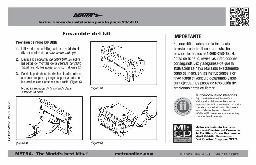
Provisión de radio ISO DDIN
1. Utilizando un cuchillo, corte con cuidado el divisor central de la carcasa de radio (a).
2. Deslice los soportes de doble DIN ISO sobre las patas de montaje de la carcasa del radio (a), alineando los agujeros juntos. (Figura B)
3. Desde la parte de atrás, deslice el radio entre el conjunto completo, y luego asegure la radio con los tornillos suministrados con la radio. (Figura C)
Nota: La muesca de la vivienda debe estar en la cima.
(Figura B)
(Figura C)(Figura A)
Ensamble del kit