ford escort rally preparation - double g motorsportdoublegmotorsport.com/rsprep/11-electrics.pdf ·...
TRANSCRIPT
INTRODUCTION
WHAT WITH OHMS, volts, amps, relays, polarities, and a host of otherelectric jargon, i t 's not surprising that electrics baffle so many people,including, at times, those who pronounce themselves experts. Thereare so many factors involved when an electrical fault occurs that weshould really go back to basics first of all.
About 90% of electrical problems are due to faulty connections, particularlyon batteries, alternators, lights, pumps and switches. Always ensurethat connections are grease free and tight fitting, especially snap connectors.The exception to this rule is the battery terminals which should be clean andsmeared with light grease or vaseline to protect from corrosion.
Looms or wires passing through a bulkhead or bracket must not be allowedto chafe as this is a prime cause of dead shorts, and can lead to an electricalfire. Always use grommets, tape or even rubber tubing around the hole inquestion. Looms should be clipped where they hang free; the best clip touse here is an insulated 'B' type. If a standard loom is used, incorporatingthe standard fuse box, always use the correct amperage fuse. Do not betempted to use an oversize fuse to overcome an overloading problem - thisis defeating the object of having a fuse anyway.
Fuses should be easy to see whether they have blown, and also easy toreplace. Obviously, the box should be away from sources of intense heat,ie exhaust pipes. One point, Boreham never fuse the headlights. This isnot a 'must', but if headlights are fused, make sure they are NOT both onthe same fuse!
When adding a loom for auxiliaries, try and obtain a different colour wirefor each item. Believe me, ten red wires through a hole in the bulkheadis a real headache to trace when only one or two auxiliaries have a fault.Also, do not paint over the wires should you decide the 'banger' needs anunder bonnet re spray. A neat and tidy wiring job is worth the extra bitof time it takes to prepare and looks good.
Now on to lights themselves. Headlights, spots and fogs are an individualchoice, and is down to you. If in doubt, have a look at what everyone elseis using.
There are legal requirements for auxiliary lighting and the fittings in thediagram should be strictly adhered to, but take in one further point. Forroad events run under RAC rules, you should not have more than FOURforward pointing lights at any one time, whilst on the public highway. Thisis to try and cut down the annoyance of some of the solar systems chargingaround the lanes that we used to have. On stages though you can, of course,use all six lights.

11.2. LIGHTS
When fitting spot or fog lights, it's a good idea to make up a separate loomfrom the cockpit to the lamps. Have a junction in the loom about 4" fromthe lamp, which makes removal and changing much easier. Individualearths for each lamp are a must.
Lights should be set up to personal preference, but don't forget club rallyingin this country is not on closed roads, so don't annoy other road users.Remember six lamps is the legal maximum (in practice you don't need moreanyway).
To keep your lights at their best, the source of power, the alternator, andbattery must be good and reliable. Remember to tightly secure the battery- something that scrutineers nearly always check. The 3" pulley on thealternator is the recommended size to use because it has the advantage ofa low speed charge. The theory here is the bigger the pulley, the betteras far as the battery is concerned.
With all the lamps and extras on a rally car, you need a good 'storagespace' so a good battery is vital. The Ford heavy duty 57 amp/hr isadequate for most people.
To help decide which charging system would be necessary when extralights, and all the extras are fitted on a rally car, the calculation shouldbe as follows:
Headlights
Spot Lights
Side Rear No Plate
Dash
Brake Lights
Fuel Pump
Flashers 48W
20W
48W
4W
30W
11OW
110W
The lighting total is 254 Watts. This converted into amps (that is dividedby 12) gives 21 amps. Usually, the standard fittings, such as ignition,takes 3 amps, heater 4 amps and wipers 3 amps, giving a total of 33 amps,so you need at least 40 amps output.
One final point, whenever the charging system is changed, or alternatorswapped, always have the control box or regulator checked and adjusted tosuit power and battery. Over charging can cause just as much trouble asunder charging. It will give you blown bulbs and eventually a uselessbattery.

11. 3. WATERPROOFING
Water on the ignition side of the eletrical system is one of the best-knownways of immobilising a rally car, as anyone who has found himselfstationary with his Ford stuck motionless in a ford (sorry) will know onlytoo well.
The main cause of getting the engine drowned is via the cooling fan. Thissucks water through the radiator in the same way that it sucks through air:the water hits the fan, gets itself blown about in a very fine mist and youhave an instant dead engine. In other words, it 's this fine mist of water,which is incredibly penetrating, that has to be kept off the ignitionconnections, leads and distributor cap. Boreham have tried most of theknown spray-on goodies, which work very well indeed up to a point, butfor deep fords you need a bit extra.
The biggest, and most important, job is the distributor. One idea is toobtain one of the waterproof covers they use for BMC Minis, which hasto be used with a side-entry distributor cap. Then make sure that allthe plug leads are in really good condition and check that they are securein the distributor after you've fitted the waterproof cover. All the leadsinto the distributor should be sealed at their entry into the distributor capwith a waterproof sealant, such as Bostik or Salastic.
The next thing you need is a bit of motorcycle inner tube which will providea really tight fit over the whole unit at the point where the cap joins thebody. A piece about four inches long will have to be rolled onto the capunderneath the waterproof cover, which you also roll up out of the waywhile you're doing it. The distributor cap is then slipped onto the body,the rubber rolled back into place over both the joint and the clips. Thenyou pull the Mini cover down over the whole assembly and tape it into place.One thing you will have to watch is that the vents in the base of the distri-butor do not become obstructed, otherwise it won't breathe, it'll get dry,and it might then seize up solid.
You must use spark plug covers, preferably rubber ones, at the other endof the leads to protect the plug insulator: if they get damp you'll get arcing,misfiring and all sorts of aggravation.
The bits that supply the eletric power to the distributor - the coil ortransistor pack - need just the same amount of careful sealing. The high-tension or "king" lead should be covered by a rubber sleeve and then sealedas one, and so should all connections on this side of the ignition system.Then you get your little aerosol (one of the silicone mixtures that are onthe market) and spray all over the leads and connectors of the entire system- and don't skimp any part that might be affected by water, however wellyou think it is protected.
This silicone spray should also be applied to the spot and fog lampsconnections exposed to the elements, and if you've got children pinchsome of their plasticine, which is excellent stuff for sealing spot-lamprims or where wiring passes through rubber grommets in body panels.A dose of plasticine can also be applied where the headlamp loom entersthe body of the headlamps - in fact, you can use it on any hole that mightlet in water or even damp. If you haven't got kids or small brothers orsisters, you'll have to buy your own, in which case you can get itcoloured to match your car. It costs no more and looks a lot smarter.
There are one or two extra things, when talking about electrics, which,as far as competition cars are concerned, are necessary to comply withregulations or law.
Battery earth leads must be either painted yellow or covered in yellowtape. The battery master switch, identified by "flash and triangle"sticker, must be capable of cutting out not only the battery, but alsothe ignition: on a car equipped with an alternator, cutting out thebattery won't stop the engine.
11.4. LIGHTING REGULATIONS
The dip-switch, when operated to put the headlights onto dip, must cutout all the other main lights, leaving only the dipped beam in use. Andthe reverse light must be operated only be engaging reverse gear.
Broadly, there are two sets of regs, both are interlinked, just to complicatethings.
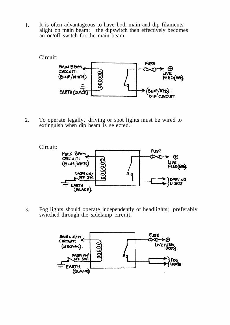
On cars registered before 31 December, 1970, a pair of auxiliaries have tobe no less than 13.8 inches apart (measured to the inner lit edges). Afterthat date, the distance of each outer lit edge to the outer extremity of the car(note that this means what it says - it could be your flared arch, or yourdoorhandle) must be less than 15.8 inches.
To cap that lot, any light mounted less than 24 inches from the ground(to its centre) can only be used legally on the public roads in fog orfalling snow. Above that height, the lights may be used in any weatherconditions, but must be extinguishable with the standard dipswitch.
Note; that no mention is made of types of lamps - if you put a drivinglamp six inches from the ground, the law thinks of it as a fog lamp.Barmy, but we have to live with it.
11. 5. SPOT LIGHT RELAYS
It's best when dealing with a complex system such as electricity to startfrom the first principles: Your car depends entirely on what happens inthat bundle of coloured wires behind the dash, and how and where thewires go; but it all starts at the battery. Like most other things insidea car, successful performance is a result of keeping it happy. Like women,batteries need attention: in the long run, simple, cheap maintenance will berewarded by way of lack of aggro and expense. It's not necessary for me togo into battery theory. Suffice it is to say that the battery functions as anelectrical reservoir as a result of a chemical reaction between lead platesand sulphuric acid. The best place for this acid - which is highly corrosive- is inside the battery. If it spills or seeps out it will commence itsdevilish work on your terminals. The posts and clamps will start to lookwhite and fluffy - at worst they will later disintegrate, at best a layer ofhighly resistive deposit will form at the electrical connection. Voltagein the system will thus be low, resulting in poor starting, dim lights andperhaps misfiring. The moral is: keep your battery clean and theconnections tight, and it won't let you down.
The battery is kept charged by the alternator or dynamo. These aregenerally trouble free if kept clean and protected from clumsy spanners.Any charging troubles can usually be traced to a 'nasty' inside the littlebox of tricks known as the Regulator. Unfortunately, if this goes on theblink there's very little you can do about it - replacement is the only answer.However, make sure the terminals are clean and tight. Should you have toremove it, please ensure the cables go back on the correct terminals - youcan check on this with the wiring diagram in the car's handbook - otherwiseyou will damage it irrepairably.
The next "component" is the wiring loom. All you need do as far as thestandard loom is concerned is to keep the connections clean and tight, andthe looms well protected from chafing. Where they pass through a hole inthe bodywork - for example the bulkhead - there should always be a rubbergrommet to prevent the cables running on the sharp metal edge. Rubberdoes, in time, perish, so preventative maintenance is again the answer toprevent disaster. Naturally this goes for any extra wiring you carry out -for example, remounting fuses within the passenger compartment, orfitting auxiliary lights. Having mentioned D-I-Y wiring, the cable you usemust be able to cope with the current it is going to be asked to carry:failure to make allowances on this score can result in voltage drop (ofwhich more later) or the cable over-heating and perhaps burning. Thiscan spell real disaster, for obvious reasons.

A good cable gauge to choose for most installations is 28/030 (metric)- which means that the cable has 28 strands each 0.030 mm in diameter.Beware of using this gauge as an alternator charging cable - it cannottake that sort of current.
Next, fuses: their job is protection of the circuit from a current thatwill damage the circuit or component. The necessary fuse value canbe worked out by the simple formula:
Rating (continuous) Wattage of component12
Note that this is a threshold value: the chosen fuse should be rated about25% higher than this. For example, two Halogen lights at 55 watts each:
Rating 11012 9. 2 amps
Choose a fuse of about 12 or 15 amps continuous rating. On a competitioncar it 's a good idea to fuse all important circuits independently, mountingthe box of tricks within the passenger compartment. The advantage of thisis that they're all easily accessible for the co-driver to deal with ifnecessary; and make sure appropriate spares are always carried.
One hang-up that all circuits suffer from, to a greater or lesser extent,is voltage drop. Any cable has a certain resistance, and therefore thevoltage available at the component will be less than 12V. It 's impossibleto completely avoid voltage drop, but it can be minimised. To give anexample of its effect; an Oscar run at 11V instead of 12V will produce25-30% less light. Points to watch are (again!) cable gauges andconnections. Also, it is likely that switches, especially if they have beenin use for some time, have slightly burnt contacts. The deposit thusformed is resistive and will cause voltage drop. So if you have a lowvoltage problem, investigate the switchgear - the answer might be toreplace it.
Another way of avoiding low voltage is to use relays. These are simplyremotely-operated heavy duty switches, capable of handling 15-18 amps.Mount the relay so that the run of cable from the battery to the componentis at the minimum, thus lessening the resistance of the circuit. Actualswitching of the relayed circuit is completely independent, whereby therelay is "fired" by providing a live feed through the relay coil, via a dash-board switch, to an earth point; this also means that each dashboardswitch only requires one cable passing through the bulkhead.
Below are three commonly used relay circuits. Obviously, the methodcan be applied to almost any other circuit within the car, with beneficialresults.
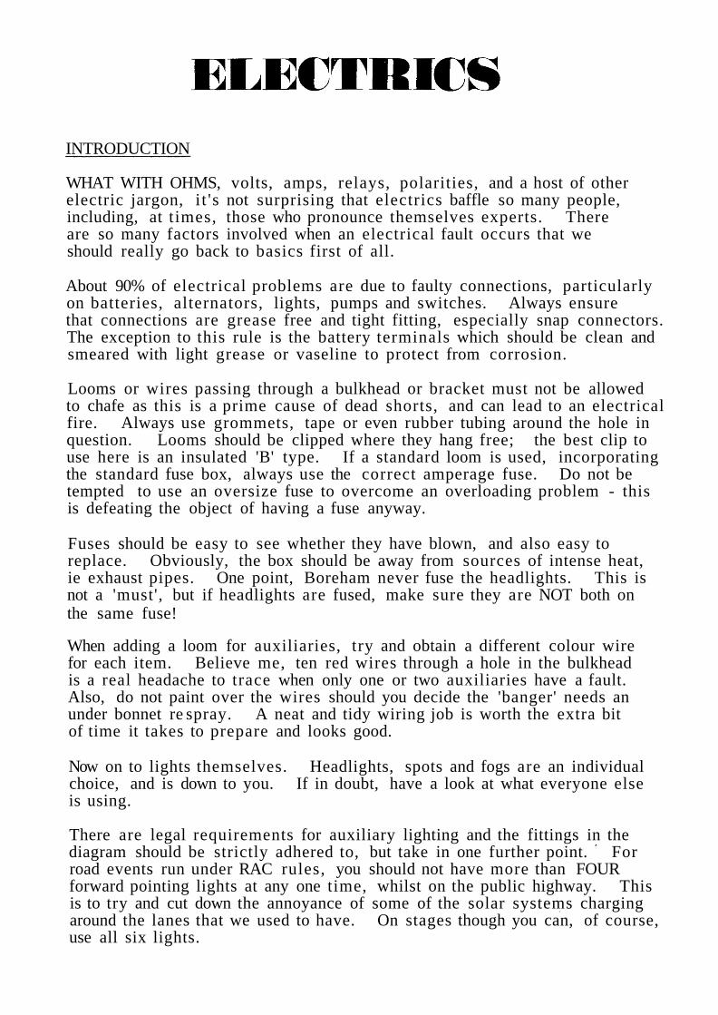
1. It is often advantageous to have both main and dip filamentsalight on main beam: the dipswitch then effectively becomesan on/off switch for the main beam.
Circuit:
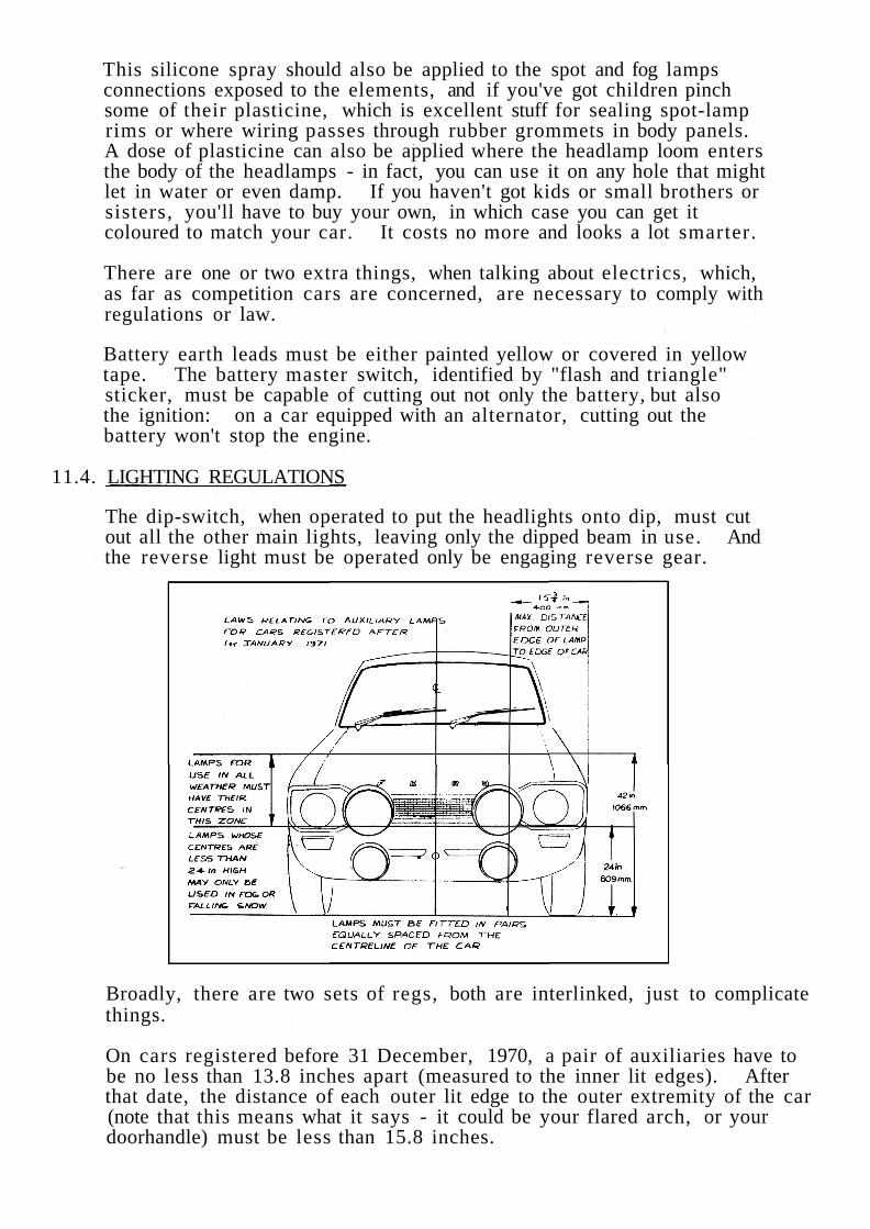
2. To operate legally, driving or spot lights must be wired toextinguish when dip beam is selected.
Circuit:
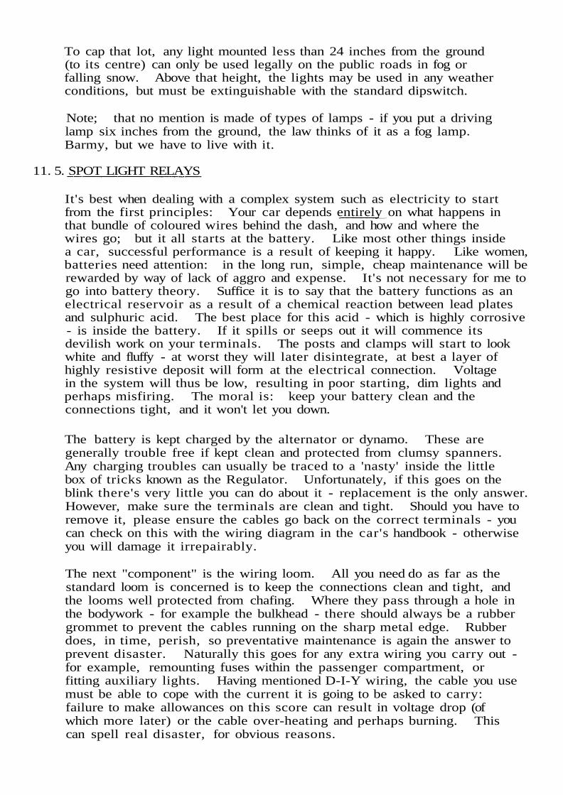
3. Fog lights should operate independently of headlights; preferablyswitched through the sidelamp circuit.

Any make of relay is suitable, assuming the current capacityis great enough; however, the terminals of different relaysare not, surprisingly, coded differently.
The following diagrams give you some common equivalents:
One last word about relays, they are very sensitive to heatand water. They should therefore be fitted away from directheat, and in a place where they are protected from water.
11.6. CIBIE LIGHTS
A) Long Range ("Spot") LampsThese can be recognised by the almost completely clear lens -Note: not glass, but lens - it is in fact itself a complex form ofprism. The beam produced by this type is what used to be knownas a spot lamp beam. It is highly intense, and thus has thegreatest possible range in absolute terms. However, becausesheer power has been the design requirement, very little lateralillumination or spread has been provided, hence the term LongRange lamp.
Driving LampsA development on the above theme. Here, though, the lens isprovided with a larger number of separate prisms - each indi-vidually designed - in order to give adequate lateral illumination.Whereas the long range lamp has a much greater spot intensity,the driving lamp is, in fact, much better as a road illuminator,although it has not got the range capability of a long range model.Shape of the beam is roughly eliptical, to be contrasted with theround spot of the long range lamp.
Fog LampsThe most specialised light available. Here the designer has beenfaced not with giving as much light as possible on the road, but tomake possible adequate vision in poor conditions. The beam istherefore very wide (about 80° ) and sharply cut off at its upperlimit. The reason for this is to avoid, as far as possible, theback-scatter of light - that effect which precludes the use of mainbeam in fog. The lensing to give this beam is distinctive, and iscomposed completely of vertically aligned prisms. Some smallelement of scatter is allowed for above the cut off so that theposition of the light can be seen by other road users. The lightshould, of course, be mounted as low as legally allowed.
B)
C)

There is another type of lamp that is not supplied by Cibie as such, butis a derivative of the Fog lamp. The modification is very simple, andthe lamp is then known as:
D) "The Virage"If the fog lens of your fog light unit is dismantled (by leveringthe bulb holder from the reflector) you will see that the bulbis shielded by a black metal pressing, which is attached to theholder by three rivets. Drill these out, throw the black thingaway, reassemble, and you are the proud owner of a Virage.You may now ask what good is all that? The answer is thatit improves intensity of the wide beam, at the expense of thesharpness of the cut-off.
So, what is the best to use? For the first pair we would recommend apair of driving lights without hesitation, as the best all-round performers.For sheer power go to the Super Oscar. Better 'cos it's bigger'. Theother pair (you aren't really allowed more than two pairs by the RoadTraffic Act or RAC regs) is up to you to choose, but make sure they aresuitable for the type of event you are going to do. If the event is in theforests, have a pair of Fog or Virage - beam width is very useful forcorners. If you are doing a very fast, mostly straight event, try a pairof long range lamps. The range is the important thing, and if they aresupplemented by driving lights as suggested, you should have enoughlateral illumination.
You'll probably see some cars with the lower pair of lights aimed so thatthey diverge or even cross. Some folk like one pointing up, the otherdown. This is again to your own preference: up/down divergence isuseful for yumpy stages, where you need to see over a brow or up a hill,before you get to it. Lateral divergence helps vision around corners -but only very slightly.
E) Reversing LightsMost of the time, you will be driving forwards. However, even thebest can wrong-slot, and you have to use that other position on yourbox and go into reverse. Again, it's nice to see where you're going,so what about reversing lights. The law limits these to 21 wattseach, but we would recommend a Halogen Foglight for off-road use.The Cibie type 40 is ideal. Wire them into the existing circuit,using a gearbox-switched system if possible. We must stress thatthe use of Halogen 55W lamps, in this case, is technically illegal- but that's your decision.
F) HeadlightsLastly, headlamps: The make is a matter of personal preferance,but one thing you can do, assuming you are using quartz halogenunits, is to wire up both filaments on the double filament bulbs.This will shorten the bulb life very little, but gives you a goodspread of light without much effort. In other words, the dip beamremains on all the time once the headlamps are on, and is supple-mented by the main beam. This will give you the advantage of theCibie Biode system, but without the slight problem of that particularlight in adjusting the main beam relative to the dip beam.
11. 7. WIRING UP HEADLIGHTS
To make sure that the dip switch does not become overloaded, the head-light system, using double filament bulbs, as well as the auxilliarylighting, is run through relays. We use the Bosch 30 amp relay.
The best way to attack this problem of wiring is to mount the fuse boxand all lighting relays (and there are four of them) on one panel.This panel is made up from sheet ally, and is located above the parceltray on the inside of the quarter panel by three Dzus fasteners. Thepanel mounts, in which the fasteners seat, are raised from the carstructure so that the mounts for the relays and fuse box do not rubagainst the vehicle bodywork. There are multi connectors for all wiringleading to and from the panel for ease of removal. The main reason forputting all these items on one panel is to facilitate removal, and also todo a neat job if you think about it, it's almost impossible to attachfour relays and a fuse box direct to the car under the dash and make agood job of it; one relay is bad enough!
Without going into the wiring of the fuse box now (because it needs acomplete article in itself) let us simply say that it is a standard Fordfuse panel cut short. The incoming power is direct from the shunt,and in the case of the headlights, power is taken on the incoming, ienon-fused side of the box, to the relevant relays, one for dip and onefor main beam. Stopping here for one moment, you'll note that theheadlight system is not fused at all. This is really driver preference,no more, because there are two schools of thought on this one. The mainpoint against having headlights fused is that if both fuses go (which is notvery likely) you can be plunged into instant darkness. On the other hand,you should consider the more likely case of a possible electric fire beingcaused by the obliteration of one headlight in a minor incident, with atree for example, that can be caused by non fusing headlights. Anyway,it's the driver's choice, and Boreham doesn't fuse the headlight system.
On the Bosch relay, the power is taken to the terminal marked 30/51.The offtake to the lights is from the terminal marked 87. You will notethat this terminal is divided, and the power to each light is taken separ-ately to each headlight, (and indeed spotlight) by its own wire. Terminal86 goes to earth, and the remaining 85 to the dash dip and light on/offswitch.
11.8. QUARTZ BULBS
To finish, some information about the Halogen bulb. This has been knownby many names, ie Iodine , Iodine Vapour, IVB, Quartz, Quartz Iodine ,Quartz Halogen, etc, etc. They all mean the same thing: that is, the"glass" is quartz, and the gas inside is a Halogen vapour. You'll noticeone main difference between this and the conventional Tungsten bulb (bythe way, QI bulbs also have a tungsten filament), and that is that they aresmaller. The reason for this is to promote a higher operating temperatureof about 2000°C. This is the reason for the considerable gain of brightness.It is the Halogen gas inside that stops the filament deteriorating rapidly asit would do under such extreme heat, and gives it a longer life.
11.9. AMMETER /SHUNT
Let's have a bit of background first, with the Gp 4 cars, for which wemake up our own looms, and later go on to Gp I adaptations and theEscort II.
Our own loom for Roger Clark's car made up especially?
That's right. As the Gp 4 cars developed and became more sophisti-cated, various items were moved around and we started to land upwith a right hotch-potch of wires that were lengthened and thickenedchasing the components around the car. The real crisis came whenthe fuse box was moved (more of that later), and from then completelooms for each shell were made as it arrived at Boreham. Later on,when this became a standard job and all the wire lengths etc were known,we got the looms made up outside.
A typical example of one problem we faced was the use of a largeralternator to keep up with output demands. This meant the wire cablesize going up, from the alternator output cable to the shunt, to 97/012,added to which the cable in the headlight circuits, ignition and fuel pumpcircuits was increased from 14 to 28/012 (012 is standard thickness ofone strand of wire at .012").
One of the first things to realize when talking car electrics is that thegenerator, be it dynamo or alternator, must be able to take all the loadsput on it without having to lean on the battery reserve. To be able tocheck this accurately then, the first thing you must do on any seriousrally car is fit an ammeter, and an accurate one at that. You'll find thatthe standard gauge fitted, for example to the 1300GT, 1300E, Mexico,RS1600, RS2000, etc is described as a voltage charge indicator, which isnot the same thing as an ammeter. The voltage gauge tells you approx-imately the state of battery reserve, but not the state of balance in theeletrical system.
If an ammeter is not fitted, you are dependant upon the ignition warninglight to tell you when anything is wrong. This might be fine for a shoppingcar, but by the time this light appears on a rally, it's usually too late to domuch about it. An example - if one of the three phases in our rally alter-nator burns out, the ignition light won't come on, but eventually the wholesystem will drain the battery, and the middle of Kielder is not the mostconvenient place to come to a halt.
Now you know why to fit an ammeter, the $60,000 question is how to fit it.At Boreham, a standard Lucas 60-0-60 ammeter is fitted (Pt No 36408),but that's only part of the story, with this ammeter we also have to fitwhat is known as a REMOTE SHUNT in the system. To explain toget an accurate reading from the ammeter, it MUST be fitted between thepower source, the battery, and the point where all the loads (lights, wipers,horn, etc) are taken off. If all the loads are taken from the system afterthe ammeter you might as well not bother fitting one in the first place.

From the drawing, you can see that normally these loads are taken directfrom the battery side of starter solenoid, which of course links straightto the battery. The answer is then to move the offtake for the loads.Now this can be done on certain ammeters by having a vast bunch of wiresgoing to the fusebox linked directly to the gauge. In practice though, withany dashboard mounting this is very difficult and untidy, so the remoteshunt is put in the system and all the wires linked to that; in other words,it is also a remote junction box.
The shunt has a calibrated strip of copper which records the mili-voltsdrop between either end, and this is recorded on the ammeter. There aretwo types of shunt box made by Lucas, both look just the same, but one haslonger leads with the spade connectors to run to the ammeter than the other.The length of these leads is related to the calibrated strip, so they MUST NOTbe cut or lengthened.
Lucas pt Nos are: 36396
36378
short leads (with short calibrated strip)
long leads (with long calibrated strip)
On the works cars, the position of the shunt is on the back of the heater boxunder the dash. Up here, it is out of harm's way and wires cannot be pulledoff accidentally. The box looks as below and you might care to note thelarge 60 amp Lucar spade connector Pt No is: 54190552.

Having told you how to fit your ammeter in the system, it 's up to youwhere you put the gauge. In an ideal situation, the gauge needle shouldbe nicely balanced on 0-this means everything is working normally,other than when starting. Here, with a fully charged battery, which,incidentally, is around 14.2 volts (although described as a 12v unit - it 's2.35v per cell) from the voltage regulator incorporated in the back of astandard alternator, but separate on our rally alternator (which we'lltalk about at a later date), you should get a + reading on the gauge for afew miles only. After this the needle should swing back to 0 prettyquickly. A plus reading is therefore indicative of a charge beingrestored to the battery from the alternator. A negative reading ispower being drained by the system from the battery.
Works Mk 11 Escort dashboard. Note centrally positioned ammeter as only extra gauge

11.10. ALTERNATOR
Firstly then, the following simple formula will help you decide the outputneeded from the alternator:
Total Watts 12 = Amps
Therefore, add up the total wattage of your lights, flashers, heater,wiper motor, etc, divide by 12 and that will give you the minimum sizeof alternator needed.
In the majority of cases, this is going to mean using a higher outputalternator, since the standard 17 ACR Lucas unit (or equivalent) producesa maximum 35 amps under ideal conditions. Staying on the Lucas rangefor a moment, within the same casing as the 17 ACR unit is the 45 ampoutput 18 ACR, and there is a possibility of Lucas manufacturing a 55 ampoutput 20 ACR type. As said, all these are in the same machine casing(? Gp I adaptations). Two bodily larger alternators are the 23 ACR,giving 55 amps, and the 25 ACR, giving 70 amps output. The suffix 'R'here means that the regulator is incorporated in the alternator.
11.11. REMOTE REGULATORS
Now, many of you will have heard about remote regulators being neededon rally cars, and to fit a sound reliable system, this is indeed necessary.An advantage of the Bosch alternator here has always been that it issupplied with a remote regulator unit. The reason for the separation ofalternator and regulator is principally engine vibration, and thumpingthat rally cars take adds even more strain. For instance, Boreham fita nylon top support arm to the alternator and a couple of metalastic busheson each base bolt, to further stop vibration, plus, of course, remotelymounting the voltage regulator and rectifier, which I'll talk about in moredetail shortly.
What can happen is that the main output lucar connector on the back of thealternator can loosen under vibration, resulting in overheating andeventually an open circuit. When this happens, the battery sensing lead(B+) can no longer sense the voltage, and the alternator becomes free togenerate its full open circuit voltage of over 150 volts. For this reasonthen, Boreham use the Lucas AC11 alternator, with remote regulator andrectifier. This unit is available in two types, a 50 amp output (Lucas PtNo 54021271) and a 60 amp output (Lucas Pt No 54021243). Because ofits greater output Boreham use the 60 amp one on the works cars.
As a point of interest, if you do overload an alternator, you will just endup flattening the battery until you stop and try to restart the engine, when
there will be that familiar click of a dead battery when the key is turned.A dynamo, however, will eventually overheat and melt the solder on theend of the commutator bars if it is overloaded, and the vehicle willeventually grind to a halt.

Having decided on the big alternator with remote regulator, let me justadvise you that you'll really have to fit the works type 'Polly Vee' drivebelt arrangement for reliability. This is a broad drive belt for whichyou will have to fit special pulleys on both crankshaft and alternator.The works found that with the estimated 6/7 bhp absorbed in drivingthe higher output alternators, the standard design belt could not takethe strain.
11.12. RECTIFIERS
Remembering that we are still only talking about the main chargingcircuit, not any of the auxiliaries, and that the regulator, which doesjust what it says in regulating the alternator's AC current to DC, arenot housed in the alternator itself, these two items have to go some-where. The works mount the 4TR control box (Lucas Pt No 37585) ona neat sheet of ally with its 6RA relay and warning light control relay(Type 3AW Pt No 38706) alongside and wired up via one multi-plug.This complete panel is then mounted inside the car under the dashboardabove the usual parcel shelf. It is held in position with four Dzusfasteners - the idea being that if a fault develops, the whole panel ischanged rather than wasting time fault finding. But, why are therethree items, the regulator, relay and warning light control?
The regulator we know about. The constantly rated relay is controlledby the ignition switch, which, in the off position de-energises the relayby open circuiting both Cl and C2 contacts. This switches off thebattery sensing supply (NW 28/. 012 in diagram) from the battery sideof the starter solenoid to + on the 4TR regulator, and at the same timeopen circuiting the + supply to the alternator field windings. Thisstops both an unwanted drain on the battery and overheating of thefield windings with the engine switched off, acting in the same way asa cut out with a generator.
You will note that the alternator has three phases, or output windings,so what stops this overheating with the ignition on and the alternatorstationary? Here the rectifier comes in, which, in converting ACto DC current, will not allow a reverse flow with the alternatorstationary.

RECTIFIER POSITION RECTIFIER UNIT
MAIN CIRCUIT

The warning light control, which picks up from the P1 terminal on therectifier unit, merely reverses the warning light current so that theignition light does the normal thing of remaining off when running, andcoming on when the engine is not turning over.
Lastly, onto the rectifier unit (Lucas Pt No 47220A). This piece ofequipment converts the alternator's AC current to a useful DC supply.Now, although its strong metal case looks pretty robust, the actualunit is very fragile and doesn't like heat at all. Being mounted in theengine bay is therefore perhaps not the best place, except that it hasto be directly linked to the alternator, with as short wires as possible.Because of the heat problem, we in fact link two rectifiers in parallelin the same box, which means each does half as much work and is lesslikely to overheat. The two rectifier offtakes are then wired togetherto give one feed to the loads supply via the shunt and then battery.Continuing on the heat problem, the rectifier, usually cooled by thealternator's own fan, must still receive a good draught of cool air.Ram effect is no good when the car is still and ticking over, so wemount it on the inner wing next to the alternator complying with thefollowing:
1.
2.
3.
4.
5.
6. Leads from the alternator to rectifier must be secured to thecar body.
Cooling air passage through the rectifier must remainunobstructed.
A good earth contact must be made between the body of the carand the rectifier.
The rectifier to be fitted away from any area subjected to directwater splash.
With the belt in position, the rectifier unit must be no more than4" from the body of the alternator and preferably with the airdeflector plate next to the alternator fan blades.
The distance between the edge of the rectifier case to the frontface of the alternator must be ½", plus or minus ¼".
We underline the requirement in No 4 because it is most important thata good earth always be maintained. Clean off any paint around themounting holes on the body, and add a smear of silicone grease toprevent rust forming.
That's it on the works main supply system then. Remember to keepthe battery terminals really clean all the time, both for good startingand, on the subject above, to enable the alternator to sense the correctvoltage all the time.

RS ELECTRICAL PARTS
RS Parts Dept have now made available the following Boreham speceletrical components.
Poly V alternator /waterpump drive:
Kit - Poly V
Pulley
9054022
CrankshaftWaterpumpAlternator
Bracket alternator mounting
Belt drive
Strap alternator adjust
Rectifier unit and regulator panel
905401990540189054017
9054020
9054021
9054082
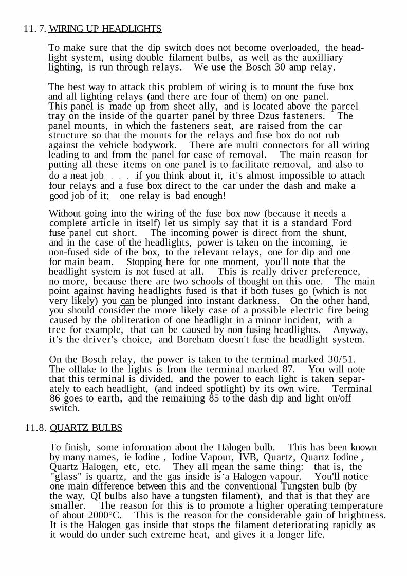
Transistorised ignition and coil pack.
11. 14. WIRING LOOM - ESCORT I
When wiring anything, be it a flexilight, spotlight or whatever, I cannotoverstress the need to stick to some form of colour code. On a comp-etition vehicle this is doubly important - tracing ever-changing wirecolours in the middle of the night can make the difference betweenfinishing and not finishing an event. Boreham base their loom on theold Lucas system, although there are added problems now for the laterEscort I's and Escort II conform to the standard European code whichis very different. Although there are mixed feelings on this new code,at least one good thing has come out of it - all live wires are red.
Anyway, here is the code used on Mk I cars, and if you're building itfrom scratch or just adding the bear necessary extras, say wires tosportlights via a relay, I suggest you use this as your reference:
Brown All live supply feeds from alternator side
of shunt.
Brown/Blue Live feed to spot light switch.
Brown /Purple Alternator Field to + on 4TR regulatorvia 6RA relay.

Brown /Green
Brown/Light Green
Brown/White
Brown/Yellow
Brown /Black
Blue
Blue /Red
Blue /Light Green
Blue /White
Blue /Yellow
Red
Red /Brown
Red/Purple
Red/White
Red/Yellow
White
White /Brown
White /Red
White /Purple
White /Green
White Light Green
White/Black
White/Pink
White /Orange
Black
Black/Yellow
Black/Green
Alternator Field to F on 4TR regulator.Screen wiper motor to switch - slow speed.
Alternator + to ampmeter shunt 97/012.Alternator sensing cable 28/012.
Ampmeter shunt to battery master switch97/012. Alternator control panel toalternator AL 14/012.
Alternator control panel to warning light14/012.
Headlight switch to dip switch.
Dip switch to dip beam.
Screen wiper motor to switch - fast speed.
Dip switch to main beam.
Spot lights.
Side and tail lights.
Tachometer illumination (unswitched).
Map reading light.
Panel light switch to panel lights (instruments).
Fog lights.
Ignition switch controlled circuits.
Oil warning.
Starter solenoid from ignition switch.
Feed to fuel pumps.
Link to second fuel pump.
Feed to heater motor (fused).
Coil Neg to distributor LT.
Cigar lighter and radiator fan warning lightfrom Aux Post, on ignition switch.
Feed to wiper motor (fused).
All earth connections.
Override manual switch to radiator fan relay.
Thermal switch to radiator fan relay.
Purple
Purple /Brown
Purple /Black
Purple /Red
Purple /White
Purple /Yellow
Green /Brown
Green /Blue
Green /Red
Green /Purple
Green /White
Green /Yellow
Green /Black
Green /Slate
Light Green
Light Green /Brown
Light Green /Black
Clock and Halda lights.
Horn supply.
Horn buttons to relay.
Boot and bonnet lights.
Interior light switches.
Horn to horn relay.
Reverse light.
Water temperature.
Left hand flashers.
Stop lights.
Right hand flashers.
Slow speed heater motor.
Fuel gauge.
Fast speed on heater motor.
Instrument voltage stabiliser to instruments.
Flasher switch to flasher unit.
Screen washer.
11. 15. WIRING LOOM - ESCORT II (EUROPEAN STANDARDISED)
Brown
Black
Blue
Black/Yellow
Black/Red
Black/Blue
Black/White
Black/Green
Blue /Black
Blue /Light Green
Blue /White
Earth (negative).
Coil in line resistance to give 6 volts.(Ballast resist for starting)Fuse 6 & 7 - see below - to:1) Back up lights2) Heated rear window (control of relay)3) Brake lights.
Ignition switch from alternator.
Ignition controlled feeds.
1) Ignition switch to s tar ter solenoid
2) Brake light switch.
Windscreen washer motor.
Left hand indicators.
Right hand indicators.
Fuel gauge.
Oil warning light.
Main beam warning light.

Black /White /Green
Black/Purple
Black /Red /Yellow
Black/White
White
Yellow
Yellow/White
Grey/Black
Grey/Red
Grey/Yellow
Red
Purple
11.16. FUSE BOXES
Flasher relay.
Ignition controlled supply to wiper.
Ignition controlled supply to heater blower.
Supply from No 4 fuse to r. h. headlamp mainbeam.
1) Loop from r . h . to 1. h. headlamp main beam2) Main beam feed to No 4 fuse from column
lighting switch.
1) Dip beam feed to No 4 fuse from columnlighting switch.
2) Loop from r . h . to l .h . headlamp dip beam.
Supply from No 5 fuse to r . h . headlamp dipbeam.
Left hand front side and tail light.
Right hand front side and tail light.
Instrument panel illumination.
1) Interior light2) Ignition switch feed3) Heated rea r window4) Alternator output5) Feed from battery.
(Most reds should be common (unswitched andunfused) live supplies through soldered connections)
Brake fluid warning light level switch - to 2 pinplug, then to brown and brown/yellow.
Using the Escort II wiring as above, the fuse box, mounted on the dash paneltop in the engine bay, can be wired in as follows:
No 1 fuse 8A To: Interior lamp redCigar lighter redEmergency flasher red
Supply: Red/Blue 28/012Soldering connection to alternator and battery(red) in engine compartment.
No 2 fuse 8 A To: Side light l .h. grey/blackTail light l .h. grey /blackNumber plate light
Supply: Grey 14/012To fuse from 9 pin socket into column switch.Common supply (link) No 3 fuse.
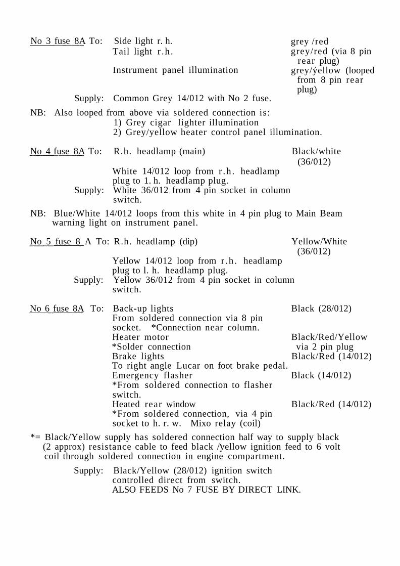
No 3 fuse 8A To: Side light r. h.Tail light r .h .
Instrument panel illumination
grey /redgrey/red (via 8 pin
rear plug)grey/yellow (looped
from 8 pin rearplug)
Supply: Common Grey 14/012 with No 2 fuse.
NB: Also looped from above via soldered connection is:1) Grey cigar lighter illumination2) Grey/yellow heater control panel illumination.
No 4 fuse 8A To: R.h. headlamp (main) Black/white(36/012)
White 14/012 loop from r .h . headlampplug to 1. h. headlamp plug.
Supply: White 36/012 from 4 pin socket in columnswitch.
NB: Blue/White 14/012 loops from this white in 4 pin plug to Main Beamwarning light on instrument panel.
No 5 fuse 8 A To: R.h. headlamp (dip) Yellow/White(36/012)
Yellow 14/012 loop from r .h . headlampplug to l. h. headlamp plug.
Supply: Yellow 36/012 from 4 pin socket in columnswitch.
No 6 fuse 8A To: Back-up lights Black (28/012)From soldered connection via 8 pinsocket. *Connection near column.Heater motor Black/Red/Yellow*Solder connection via 2 pin plugBrake lights Black/Red (14/012)To right angle Lucar on foot brake pedal.Emergency flasher Black (14/012)*From soldered connection to flasherswitch.Heated rear window Black/Red (14/012)*From soldered connection, via 4 pinsocket to h. r. w. Mixo relay (coil)
*= Black/Yellow supply has soldered connection half way to supply black(2 approx) resistance cable to feed black /yellow ignition feed to 6 voltcoil through soldered connection in engine compartment.
Supply: Black/Yellow (28/012) ignition switchcontrolled direct from switch.ALSO FEEDS No 7 FUSE BY DIRECT LINK.

No 7 fuse 8A To: Windscreen washer motor Black /Blue4 pin column switch Black /Purple
(28/012)(via soldered connection and then 14/012 toswitch)Windscreen wiper motor Black/PurpleFrom soldered connetion to 3 pinsocket in wiper motor.Tacho Black/Yellow
(14/012)From Black/Purple soldered connectionon Fuse 710 pin column socket Black/Yellow
(14/012)From Black/Purple soldered connectionInstrument Panel Black/Yellow
(14/012)From Black/Purple soldered connectionto black socket in instrument panel.
NO CONNECTED INTO LOOM - SPAREFuse No 8
Fuse box and starter solenoid location.
11. 17. PETROL PUMPS
It is essential, when building a Group 4 car to use twin eletric fuel pumpsin conjunction with either a bag tank or an alloy fuel tank, preferablyincorporating a reserve tank.
The best pumps to use are undoubtedly Bendix pumps. As all Escortsare wired to a negative earth system, make sure though, that you purchasea negative earth pump.
Bendix have three pumps available:
- Silver top (25 gallons/hour)
- Blue " (35 " " )
- Red " (45 " " )
The one to go for is the Blue top, which incidentally is now made underlicence by Facet, so don't let the different make bother you.
The pumps should be mounted horizontally in the boot, with one pumpconnected to the main tank and the second pump to the reserve tank.The pumps should be activated by a three position switch (Off, Pump 1,Purnp 2) mounted to the dashboard and connected to the ignition.
It is also advisable to use a fuel filter (Filter King etc) to reduce the fuelpressure, as Bendix pumps deliver at about 7 psi, which is liable to blowthe needle valves on your carburettors. Weber recommend a maximumfuel pressure of 4. 5 psi, but in practice about 4. 5 to 5 psi is needed asany less is likely to cause fuel starvation.
11. 18. WIRING PETROL PUMPS
A 28/012 cable (in our case coded white) is taken from the fuel box, to adash mounted switch. From the switch, two wires are taken, againboth 28/012, one white /green, the other white /purple, and each runningvia a cartridge fuse each to their own fuel pumps in the boot. Number 1pump has its offtake in the tank some three inches higher than Number 2.This means that, in the event of pump failure, the driver can simplyswitch over to the Number 2 pump before the car comes to a halt. Italso acts as a reserve, having a lower offtake than the Number 1 pump.So, whatever the fuel problem, the driver just flicks the switch in theappropriate direction.

Location of two petrol pumps in boot, next to oil tank, withconnecting filter.

11.19. LAMP BRACKETS
On the Mk II Escorts, as on the Mk I's, the works make their ownauxilliary mounting brackets that are light, strong and most important,do not vibrate at all. On Escort II, the front ¼ bumpers are used asmounting points, whereas on the older car, although the principle anddesign was similar, the 1 up /I down light system brackets were directbody mounted.
For those of you building up Escort II's, here are the dimensions:
The bracket itself is made in two parts, an L bracket and flat top. Thematerial is 3/8" dural for strength and lightness, with the L bracket3/16" thickness. For the Mk I, the rearward projection is cut by 2"This is because the whole bracket mounts to the front apron, not thebumper.