ford automatic transmission troubleshooter reference manual · ford automatic transmission...
TRANSCRIPT
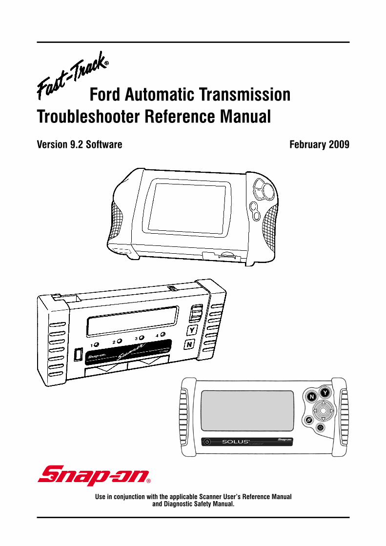
Ford Automatic Transmission Troubleshooter Reference Manual
Use in conjunction with the applicable Scanner User’s Reference Manual and Diagnostic Safety Manual.
Version 9.2 Software February 2009

Safety Warnings and CautionsRefer to Diagnostic Safety Manual.
Version 9.2February 2009
BEFORE OPERATING THIS UNIT, PLEASE READ THIS MANUAL
AND ANY APPLICABLE SCANNER AND SAFETY MANUALS.
Every effort has been made to ensure that the information in this manual and software is accurate. The right is reserved to change any part at any time without prior notice.
No responsibility is taken for any technical or printing errors that might occur in this manual or software.
Copyright © 2009 Snap-on Technologies Inc.
Ford Automatic Transmission Troubleshooter Reference Manual
FordIntroduction
About the Fast-Track Troubleshooter System ..................................2 Using Troubleshooter Effectively .....................................................4 Troubleshooting Trouble Codes .......................................................4 General Circuit Testing Information ..................................................6 ECU Module Identification Codes ....................................................9 Ford Reference Bulletins Index ........................................................10
CAUTION
1. Always read Scanner and Safety Manuals first.
2. Ensure correct ID on Scanner and connections correct for vehicle.
3. Always check for fault codes first – checking KOEO, KOER and memory codes in Self Tests.
PAGE 1
PAGE 2
About the Fast-Track Troubleshooter System
Snap-on’s Fast-Track Troubleshooter is a unique time saving diagnosis tool which compliments the
Snap-on Scanner. They are used in unison to diagnose and repair automatic transmission related problems.
The Troubleshooter can incorporate known faults and repair tips, and rebuilding, and technical assistance
to reduce the down time of diagnosis, therfore saving you time and money. This product is researched and
made in Australia for Australian Vehicles. Information is researched from throughout Australia from a large
network of technical sources with vast knowledge of product.
The Reference Manual supplied in this kit contains additional information to support many Troubleshooter
tips when special instructions, specifications, pinouts and wiring diagrams are needed as indicated by the
Scanner.
IMPORTANT: The Fast-Track Troubleshooter system contains information on the most common code
problems and driveability complaints on the above vehicles. It does not, however, contain information for
every possible code and every possible problem that could occur in all vehicles.
PAGE 3
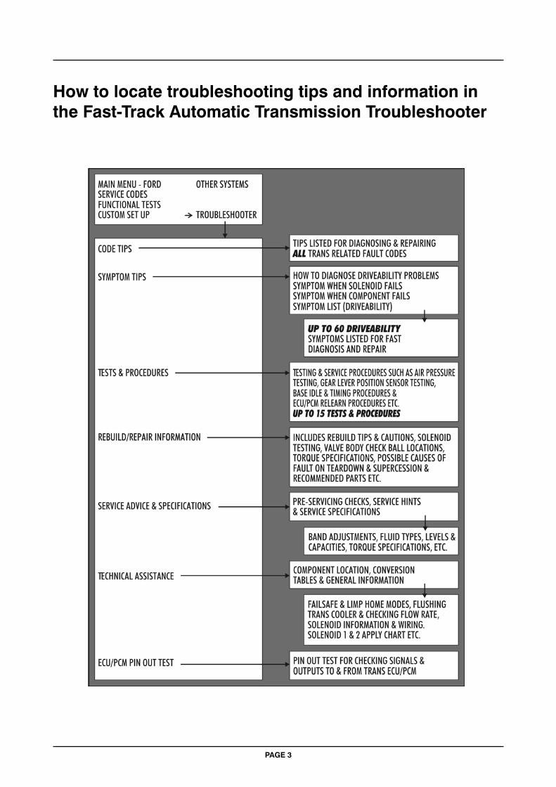
How to locate troubleshooting tips and information in the Fast-Track Automatic Transmission Troubleshooter
Using Troubleshooter Effectively
The checks in each Troubleshooter tip begin with the most likely cause of a problem or with the tests that should be made first. The checks then progress through other possible causes and tests. All checks in a tip are common causes of a problem or important basic tests, and the most important are listed first. For the most effective use of the Troubleshooter tips, follow the checks in the order in which they are given.
Many checks in the Troubleshooter tips with refer you to references in this Troubleshooter Manual. Consult the references as directed by the tips on the Troubleshooter cartridge. Trying to use the references by themselves may cause you to miss important information or to perform some test or adjustment out of sequence.
Begin with the basics
The Fast-Track Troubleshooter tips deal with automatic transmission electronics and controls. It assumes the basics have been checked. Eg: fluid level and condition, engine performance and other driveline components like brakes and differential assemblies. These should be checked before performing pinpoint tests on electronic components.
Always ensure that the following systems and components are in proper operating condition:
• Battery condition• Electrical connectors and wiring harnesses• Vacuum lines and connectors• General engine mechanical condition• Brakes and differential assemblies
Troubleshooting Trouble Codes
Ford refers to services codes as on-demand codes and memory codes, and the vehicle electronic control unit (ECU) transmits them in these groups during self-tests. On-demand codes are “hard” codes that indicate faults which are present at the time of testing. Memory codes are “soft” codes from the ECU memory of EEC systems. These indicate intermittent problems that have occurred in the past but which are not present at the time of testing.
For the key-on, engine-off self-test, the Ford Aust. EEC systems both transmit hard (on-demand) codes first, followed by soft memory codes.
Ford test procedures are very specific about the order in which self-tests should be performed and codes should be diagnosed and serviced.
The specified order for Ford tests and code diagnosis is as follows:
Key-on, engine-off (KOEO) test – This test displays on-demand hard codes present with the ignition on, but the engine not running. These are usually electrically open and short circuits and must be serviced first, before any other codes. For EEC systems, the key-on, engine-off test also displays memory codes of intermittent faults from ECU memory. These memory codes should be serviced first, after any other hard codes.
Note: On some models, a/trans codes are displayed only as memory codes.
Key-on, engine-running (KOER) test – This test displays on-demand hard codes present with the engine running. These should be serviced second, after any KOEO hard codes and before any memory codes. This test is applicable to vehicles with combined engine and trans ECU (power train control module).
PAGE 4
Functional Tests – Vehicle-specific functional tests are available on some models to help you further diagnose and troubleshoot the nature of certain codes. These tests may include Output State Check, Computed Timing, and Wiggle Tests. The engine-off and engine-running wiggle tests place the Scanner and the ECU in a stand-by mode to indicate an intermittent problem caused by wiggling electrical harnesses. If a fault occurs during a wiggle test, it is recorded in ECU memory as a soft intermittent code. The KOEO test must be repeated to read the code.
Troubleshoot Ford codes in the order in which they are listed by the Scanner. After fixing a problem, repeat the self-tests to be sure the code does not reappear. Some codes may be present as both hard and soft codes. Fixing the hard codes first may also correct problems that caused soft codes.
Code Clearing
The CLEAR CODES selection appears on the SERVICE CODES menu. You must use the CLEAR CODES selection to clear codes from the ECU. The Scanner stores all codes in its own memory. You can review or print the code list by selecting REVIEW CODES or PRINT CODES from the SERVICE CODE MENU.
Ford service procedures state that you should clear all codes after making repairs and then repeat the self-test to verify the repair. Be sure, however, to note any memory codes displayed during the self-test or saved in Scanner memory. If codes are cleared and a problem does not recur as an on-demand code when a self-test is repeated, the ECU will not transmit the code. Repeating a self-test will erase the code list from a previous test in Scanner memory – including memory codes – and replace it with a new list.
Remember that only soft memory codes can be cleared. If a code reappears when you clear codes and repeat a test, it is a hard (on-demand) code that must be serviced.
PAGE 5
General Reference
General circuit testing (voltage drop testing)
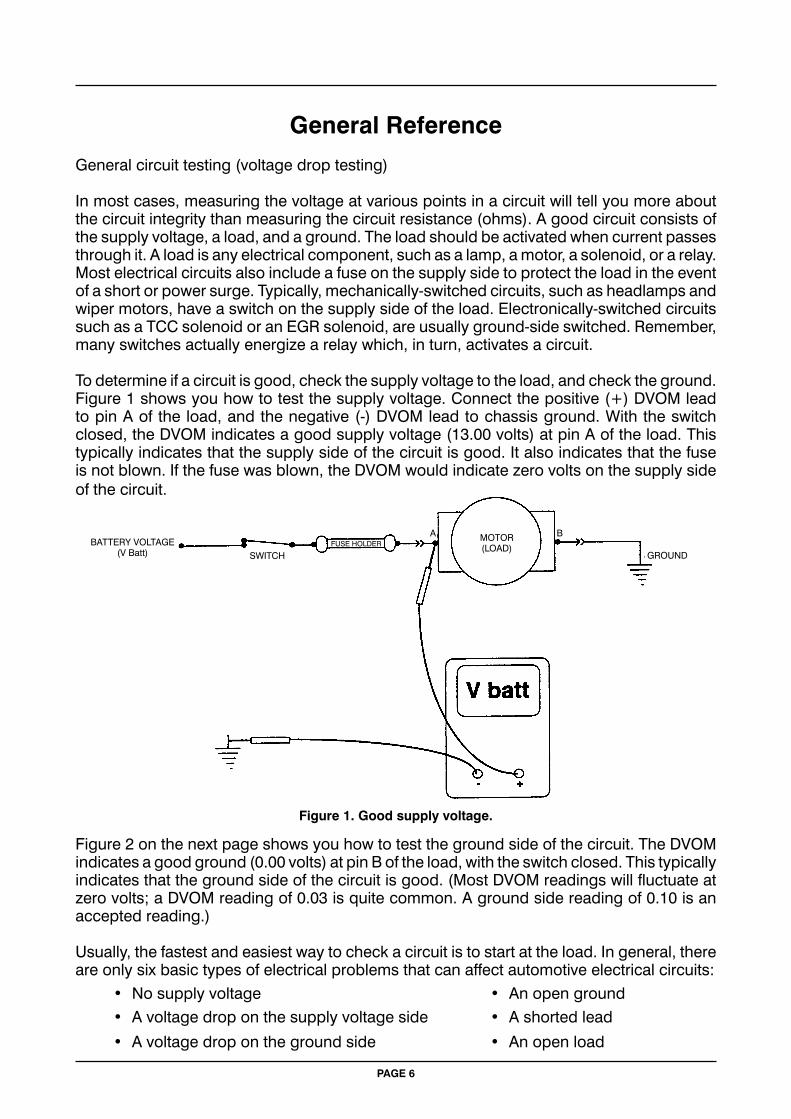
In most cases, measuring the voltage at various points in a circuit will tell you more about the circuit integrity than measuring the circuit resistance (ohms). A good circuit consists of the supply voltage, a load, and a ground. The load should be activated when current passes through it. A load is any electrical component, such as a lamp, a motor, a solenoid, or a relay. Most electrical circuits also include a fuse on the supply side to protect the load in the event of a short or power surge. Typically, mechanically-switched circuits, such as headlamps and wiper motors, have a switch on the supply side of the load. Electronically-switched circuits such as a TCC solenoid or an EGR solenoid, are usually ground-side switched. Remember, many switches actually energize a relay which, in turn, activates a circuit.
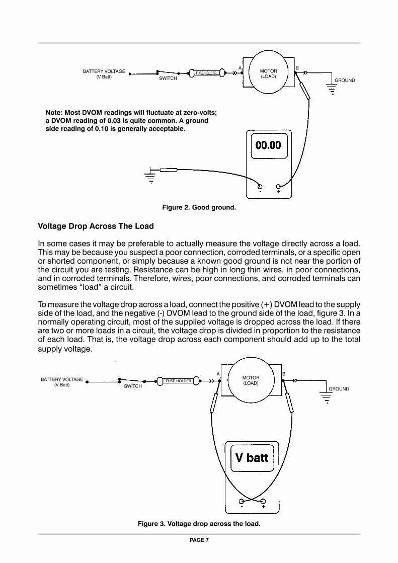
To determine if a circuit is good, check the supply voltage to the load, and check the ground. Figure 1 shows you how to test the supply voltage. Connect the positive (+) DVOM lead to pin A of the load, and the negative (-) DVOM lead to chassis ground. With the switch closed, the DVOM indicates a good supply voltage (13.00 volts) at pin A of the load. This typically indicates that the supply side of the circuit is good. It also indicates that the fuse is not blown. If the fuse was blown, the DVOM would indicate zero volts on the supply side of the circuit.
Figure 2 on the next page shows you how to test the ground side of the circuit. The DVOM indicates a good ground (0.00 volts) at pin B of the load, with the switch closed. This typically indicates that the ground side of the circuit is good. (Most DVOM readings will fluctuate at zero volts; a DVOM reading of 0.03 is quite common. A ground side reading of 0.10 is an accepted reading.)
Usually, the fastest and easiest way to check a circuit is to start at the load. In general, there are only six basic types of electrical problems that can affect automotive electrical circuits: • No supply voltage • An open ground • A voltage drop on the supply voltage side • A shorted lead
• A voltage drop on the ground side • An open load
Figure 1. Good supply voltage.
BATTERY VOLTAGE(V Batt) SWITCH
MOTOR(LOAD)
GROUNDFUSE HOLDER
A B
PAGE 6
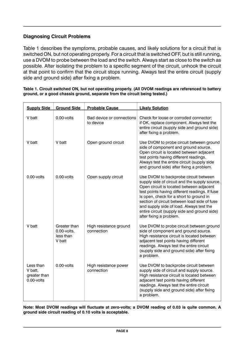
Voltage Drop Across The Load
In some cases it may be preferable to actually measure the voltage directly across a load. This may be because you suspect a poor connection, corroded terminals, or a specific open or shorted component, or simply because a known good ground is not near the portion of the circuit you are testing. Resistance can be high in long thin wires, in poor connections, and in corroded terminals. Therefore, wires, poor connections, and corroded terminals can sometimes “load” a circuit.
To measure the voltage drop across a load, connect the positive (+) DVOM lead to the supply side of the load, and the negative (-) DVOM lead to the ground side of the load, figure 3. In a normally operating circuit, most of the supplied voltage is dropped across the load. If there are two or more loads in a circuit, the voltage drop is divided in proportion to the resistance of each load. That is, the voltage drop across each component should add up to the total supply voltage.
Figure 3. Voltage drop across the load.
Figure 2. Good ground.
BATTERY VOLTAGE(V Batt) SWITCH GROUND
MOTOR(LOAD)
GROUND
MOTOR(LOAD)
BATTERY VOLTAGE(V Batt) SWITCH
FUSE HOLDER
FUSE HOLDER
A B
A B
PAGE 7
Note: Most DVOM readings will fluctuate at zero-volts; a DVOM reading of 0.03 is quite common. A ground side reading of 0.10 is generally acceptable.
Supply Side Ground Side Probable Cause Likely Solution
V batt 0.00-volts Bad device or connections Check for loose or corroded connector; to device if OK, replace component. Always test the entire circuit (supply side and ground side) after fixing a problem.
V batt V batt Open ground circuit Use DVOM to probe circuit between ground side of component and ground source. Open circuit is located between adjacent test points having different readings. Always test the entire circuit (supply side and ground side) after fixing a problem.
0.00-volts 0.00-volts Open supply circuit Use DVOM to backprobe circuit between supply side of circuit and the supply source. Open circuit is located between adjacent test points having different readings. If fuse is open, check for a short to ground in section of circuit between load side of fuse and supply side of load. Always test the entire circuit (supply side and ground side) after fixing a problem.
V batt Greater than High resistance ground Use DVOM to probe circuit between ground 0.00-volts, connection side of component and ground source. less than High resistance circuit is located between V batt adjacent test points having different readings. Always test the entire circuit (supply side and ground side) after fixing a problem.
Less than 0.00-volts High resistance power Use DVOM to backprobe circuit between V batt, connection supply side of circuit and supply source. greater than High resistance circuit is located between 0.00-volts adjacent test points having different readings. Always test the entire circuit (supply side and ground side) after fixing a problem.
Note: Most DVOM readings will fluctuate at zero-volts; a DVOM reading of 0.03 is quite common. A ground side circuit reading of 0.10 volts is acceptable.
PAGE 8
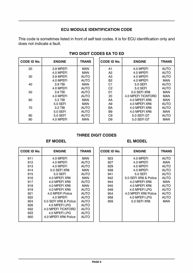
Diagnosing Circuit Problems
Table 1 describes the symptoms, probable causes, and likely solutions for a circuit that is switched ON, but not operating properly. For a circuit that is switched OFF, but is still running, use a DVOM to probe between the load and the switch. Always start as close to the switch as possible. After isolating the problem to a specific segment of the circuit, unhook the circuit at that point to confirm that the circuit stops running. Always test the entire circuit (supply side and ground side) after fixing a problem.
Table 1. Circuit switched ON, but not operating properly. (All DVOM readings are referenced to battery ground, or a good chassis ground, separate from the circuit being tested.)
20 3.9 MPEFI MAN A1 4.0 MPEFI AUTO 4.0 MPEFI MAN A2 4.0 MPEFI AUTO 30 3.9 MPEFI AUTO A3 4.0 MPEFI AUTO 4.0 MPEFI AUTO B2 4.0 MPEFI MAN 40 3.9 TBI MAN C1 5.0 SEFI AUTO 4.0 MPEFI AUTO C2 5.0 SEFI AUTO 50 3.9 TBI AUTO D1 5.0 SEFI XR8 MAN 4.0 MPEFI AUTO 20 4.0 MPEFI TICKFORD MAN 60 3.2 TBI MAN AA 4.0 MPEFI XR6 MAN 5.0 SEFI MAN A9 4.0 MPEFI XR6 AUTO 70 3.2 TBI AUTO BA 4.0 MPEFI XR6 AUTO 5.0 SEFI AUTO B9 4.0 MPEFI XR6 MAN 80 5.0 SEFI AUTO C9 5.0 SEFI GT AUTO 90 4.0 MPEFI MAN D9 5.0 SEFI GT MAN
ECU MODULE IDENTIFICATION CODE
This code is sometimes listed in front of self test codes. It is for ECU identification only and does not indicate a fault.
TWO DIGIT CODES EA TO ED
CODE ID No. ENGINE TRANS CODE ID No. ENGINE TRANS
THREE DIGIT CODES
CODE ID No. ENGINE TRANS CODE ID No. ENGINE TRANS
911 4.0 MPEFI MAN 923 4.0 MPEFI AUTO 912 4.0 MPEFI AUTO 927 4.0 MPEFI MAN 913 4.0 MPEFI AUTO 929 4.0 MPEFI AUTO 914 5.0 SEFI XR8 MAN 939 4.0 MPEFI AUTO 915 5.0 SEFI AUTO 941 5.0 SEFI AUTO 916 4.0 MPEFI XR6 MAN 942 5.0 SEFI XR8 & Police AUTO 917 4.0 MPEFI XR6 AUTO 944 4.0 MPEFI XR6 MAN 918 4.0 MPEFI XR6 MAN 945 4.0 MPEFI XR6 AUTO 919 4.0 MPEFI XR6 AUTO 948 4.0 MPEFI LPG AUTO 921 4.0 MPEFI Police AUTO 954 4.0 MPEFI XR6 Police AUTO 922 4.0 MPEFI AUTO 958 4.0 MPEFI LPG AUTO 924 5.0 SEFI XR8 & Police AUTO 959 5.0 SEFI XR8 MAN 926 4.0 MPEFI LPG AUTO 932 4.0 MPEFI TICKFORD AUTO 933 4.0 MPEFI LPG AUTO 950 4.0 MPEFI XR6 Police AUTO
EF MODEL EL MODEL
PAGE 9
Ford Reference Bulletins
Ref. No. Page Subject
F001 12 EAII/EB 6 cyl model auto trans wiring diagram and connectors
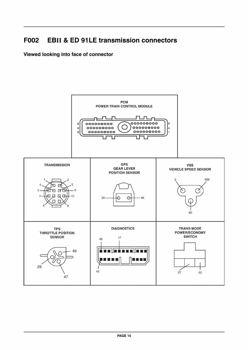
F002 14 EBII/ED 6 cyl model auto trans wiring diagram and connectors
F003 16 EF 6 cyl model auto trans wiring diagram and connectors
F004 18 EL 6 cyl model auto trans wiring diagram and connectors
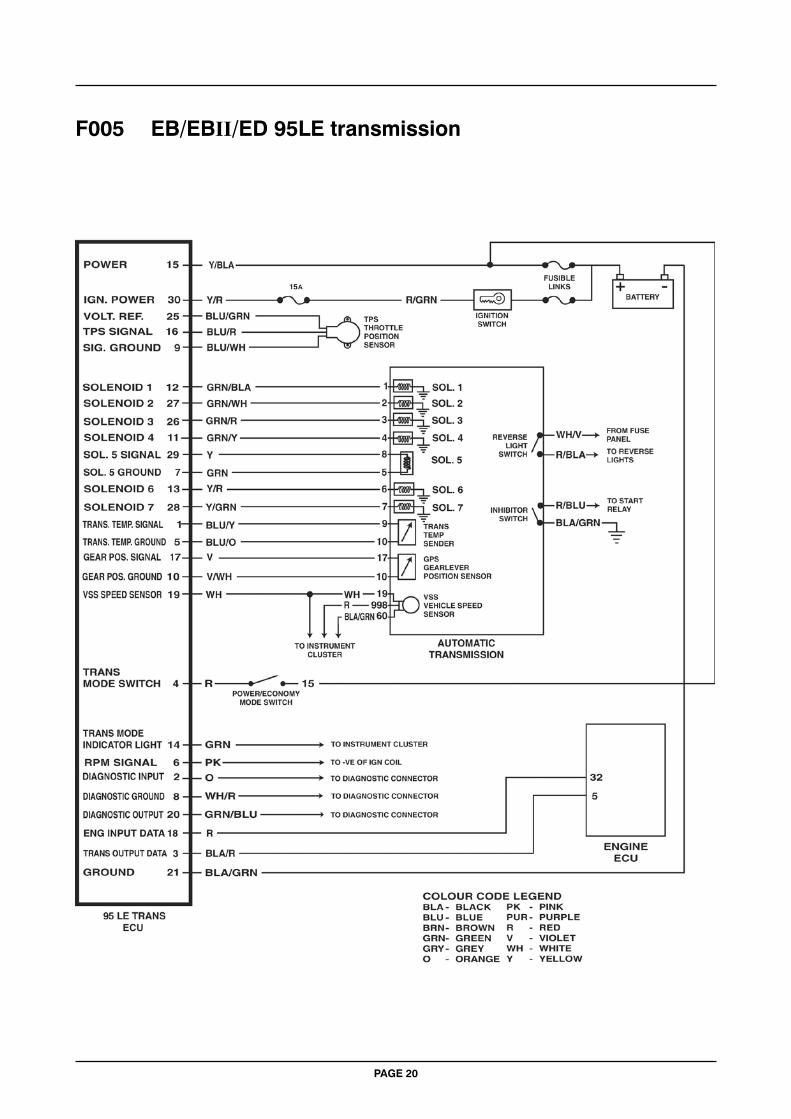
F005 20 EB/EBII/ED V8 model auto trans wiring diagram and connectors
F006 22 EF/EL V8 model auto trans wiring diagram and connectors
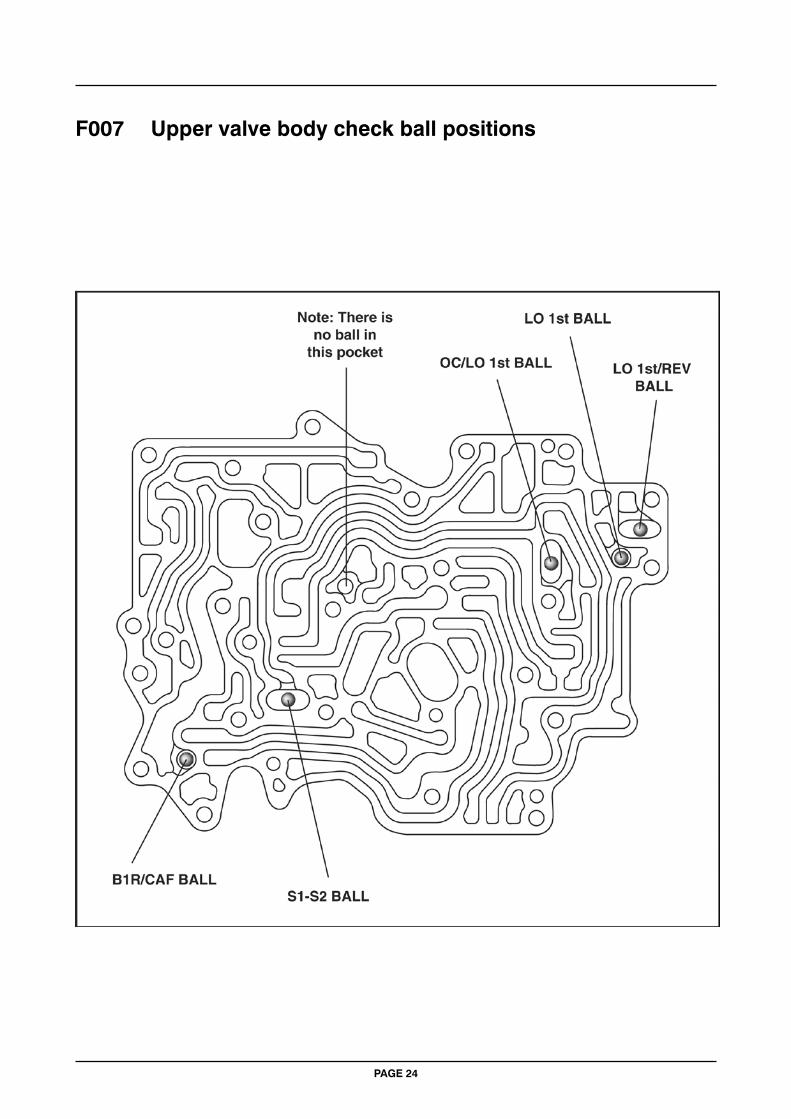
F007 24 Valve body check ball positions
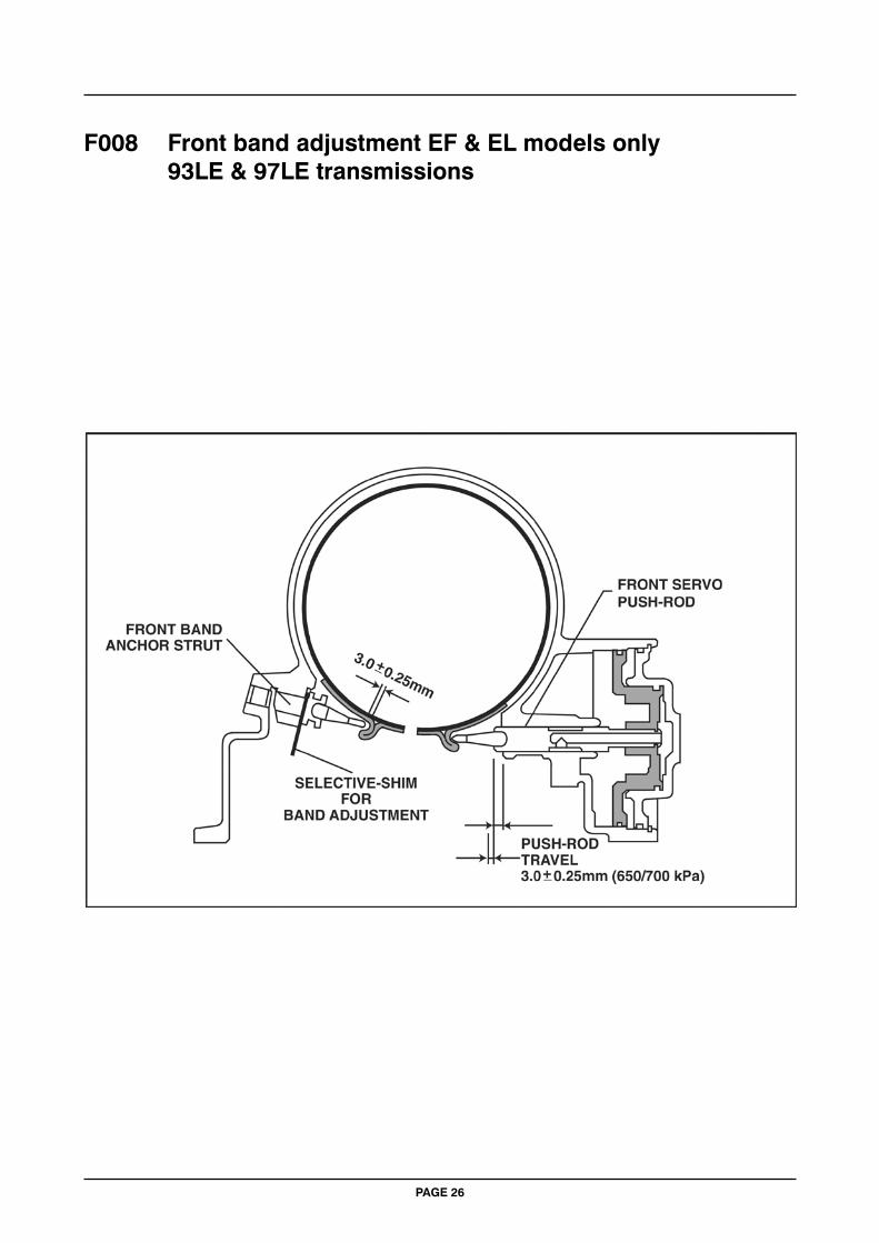
F008 26 EF/EL model front band adjustment
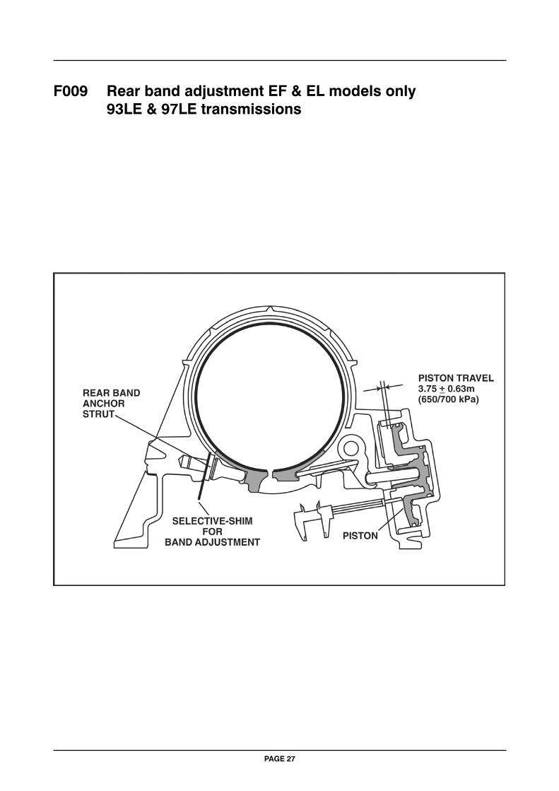
F009 27 EF/EL model rear band adjustment
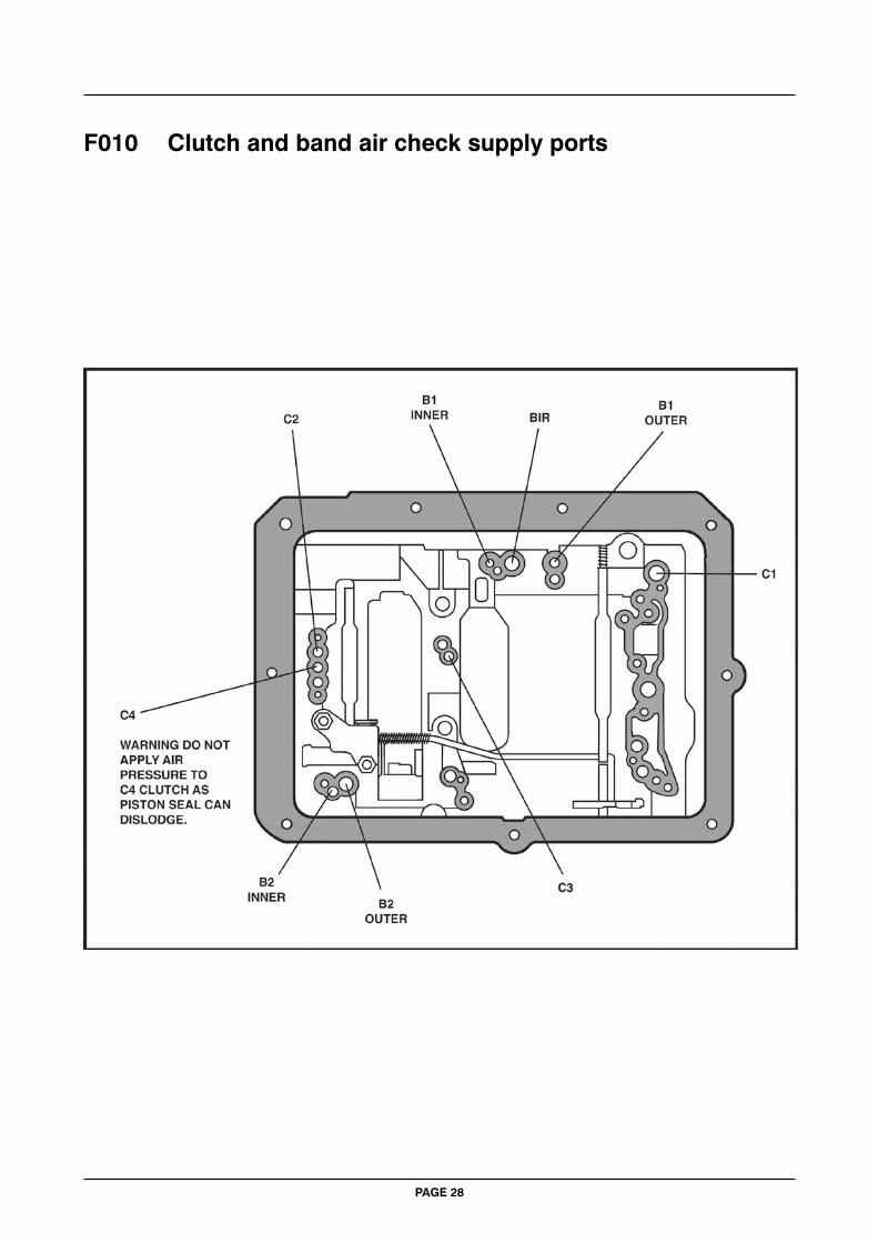
F010 28 Clutch and band air check supply ports
PAGE 10

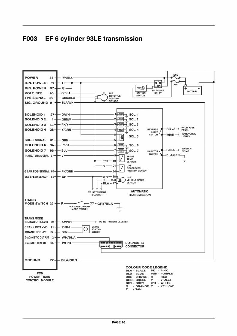
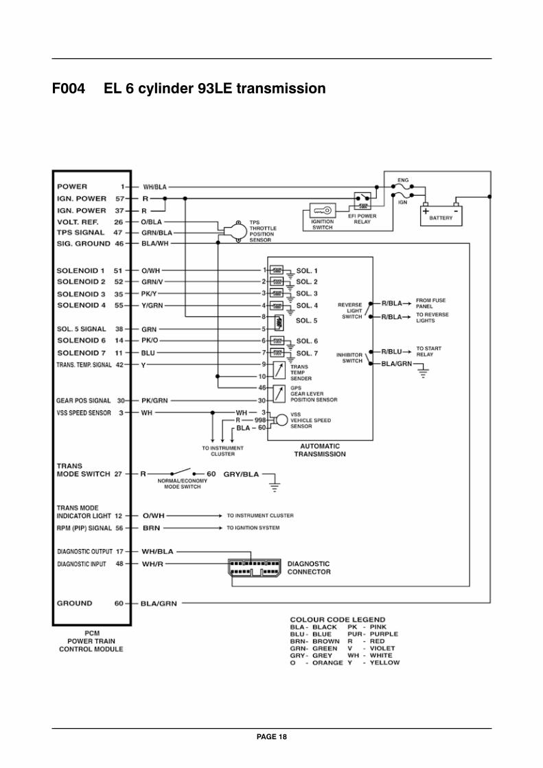
PLEASE NOTE WIRING DIAGRAM WIRE COLOURS ARE GIVEN AT THE ECU AND MAY NOT ALWAYS BE CORRECT DUE TO MANUFACTURING CHANGES IN PRODUCTION. ALSO WIRE COLOURS AT COMPONENTS AND SENSORS MAY NOT BE THE SAME AS AT THE ECU PARTICULARLY ON V8 MODELS DUE TO ENGINE BEING IMPORTED.
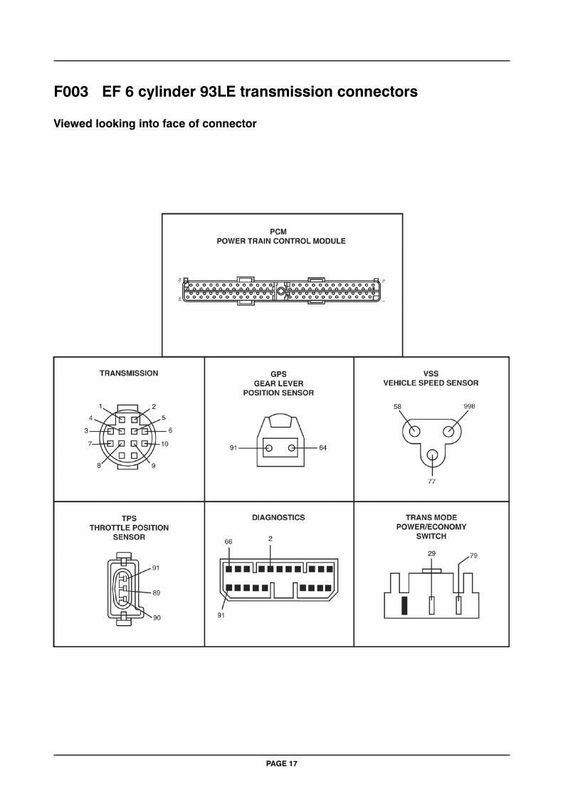
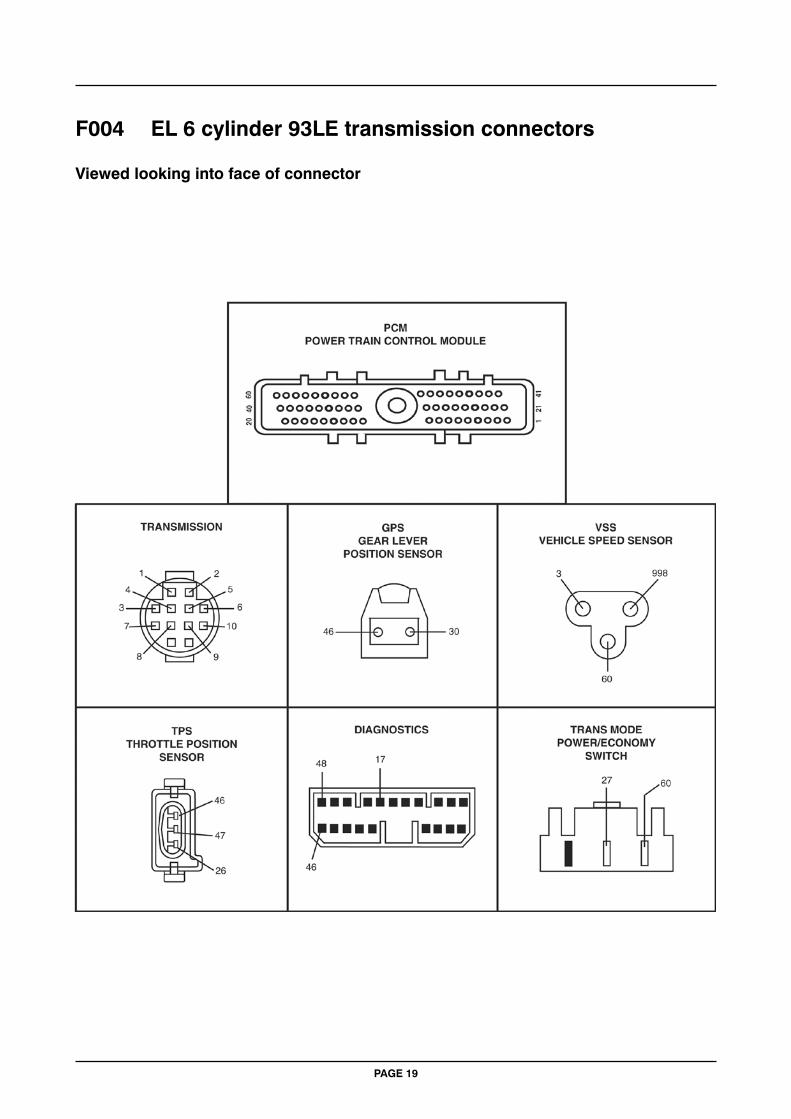
ALL CONNECTORS ARE VIEWED LOOKING INTO FACE OF CONNECTION.
PAGE 11
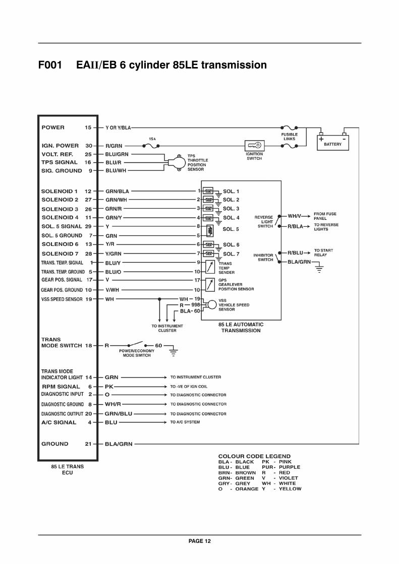
PAGE 12
F001 EAII/EB 6 cylinder 85LE transmission
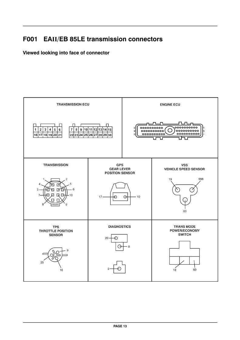
PAGE 13
F001 EAII/EB 85LE transmission connectors
Viewed looking into face of connector
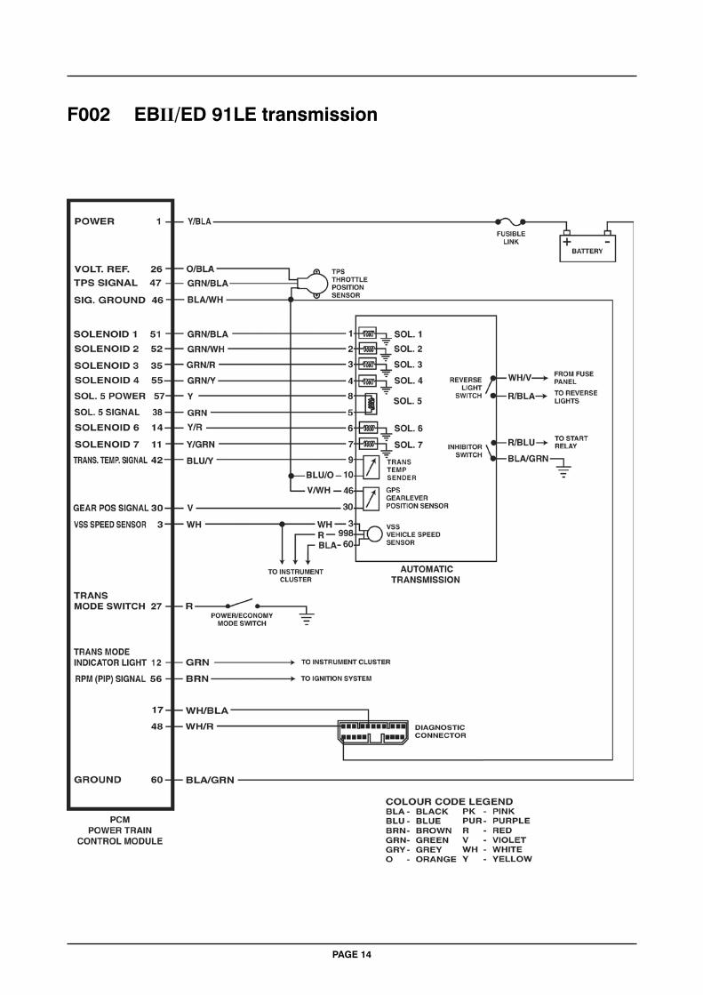
PAGE 14
F002 EBII/ED 91LE transmission
PAGE 15
F002 EBII & ED 91LE transmission connectors
Viewed looking into face of connector
PAGE 16
F003 EF 6 cylinder 93LE transmission
PAGE 17
F003 EF 6 cylinder 93LE transmission connectors
Viewed looking into face of connector
PAGE 18
F004 EL 6 cylinder 93LE transmission
PAGE 19
F004 EL 6 cylinder 93LE transmission connectors
Viewed looking into face of connector
PAGE 20
F005 EB/EBII/ED 95LE transmission
PAGE 21
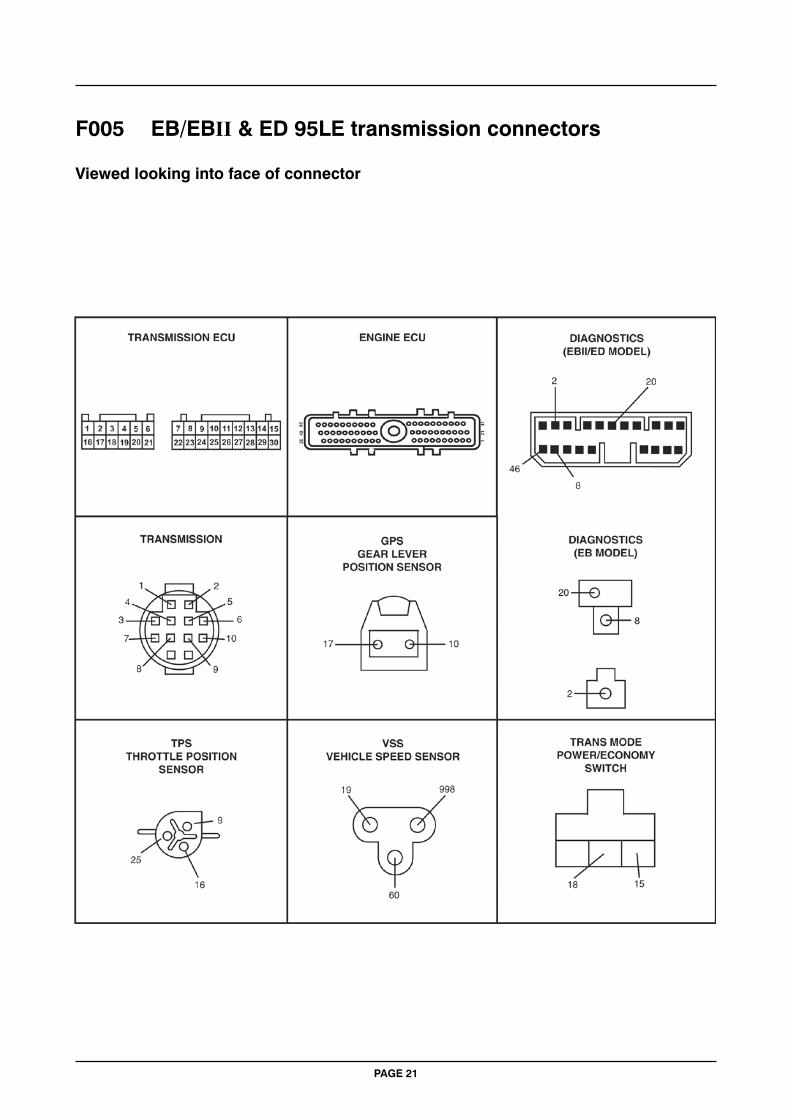
F005 EB/EBII & ED 95LE transmission connectors
Viewed looking into face of connector
PAGE 22
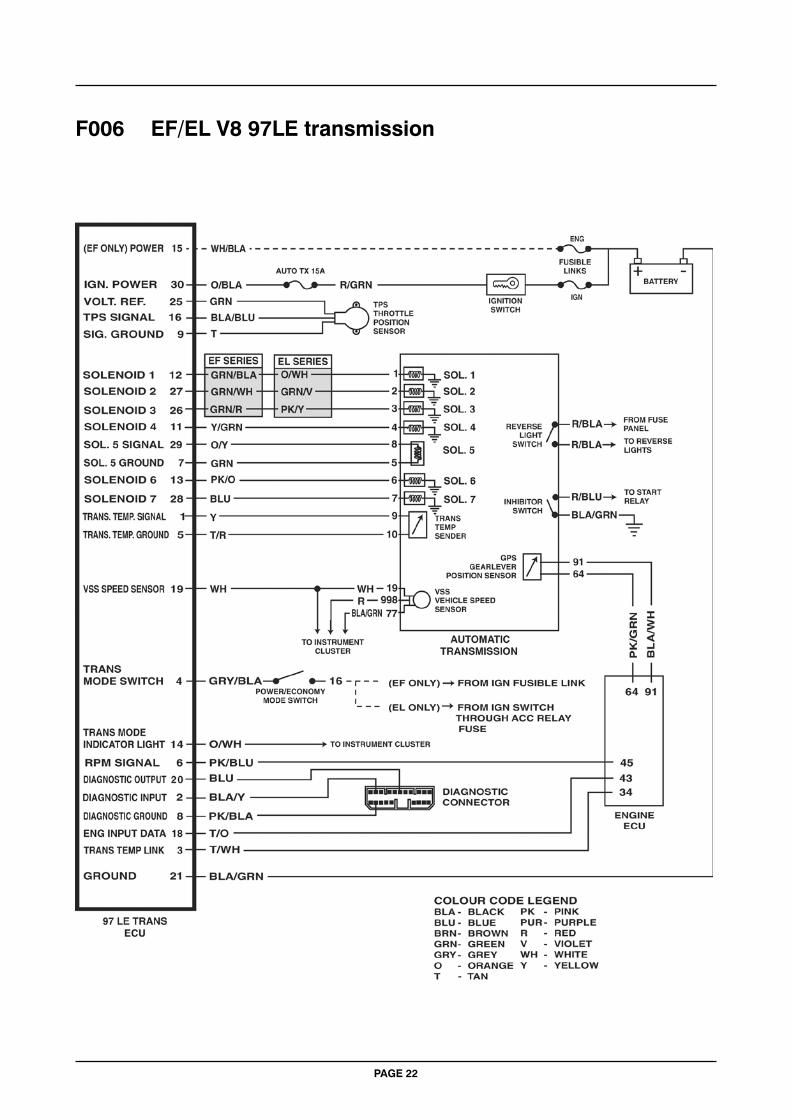
F006 EF/EL V8 97LE transmission
PAGE 23
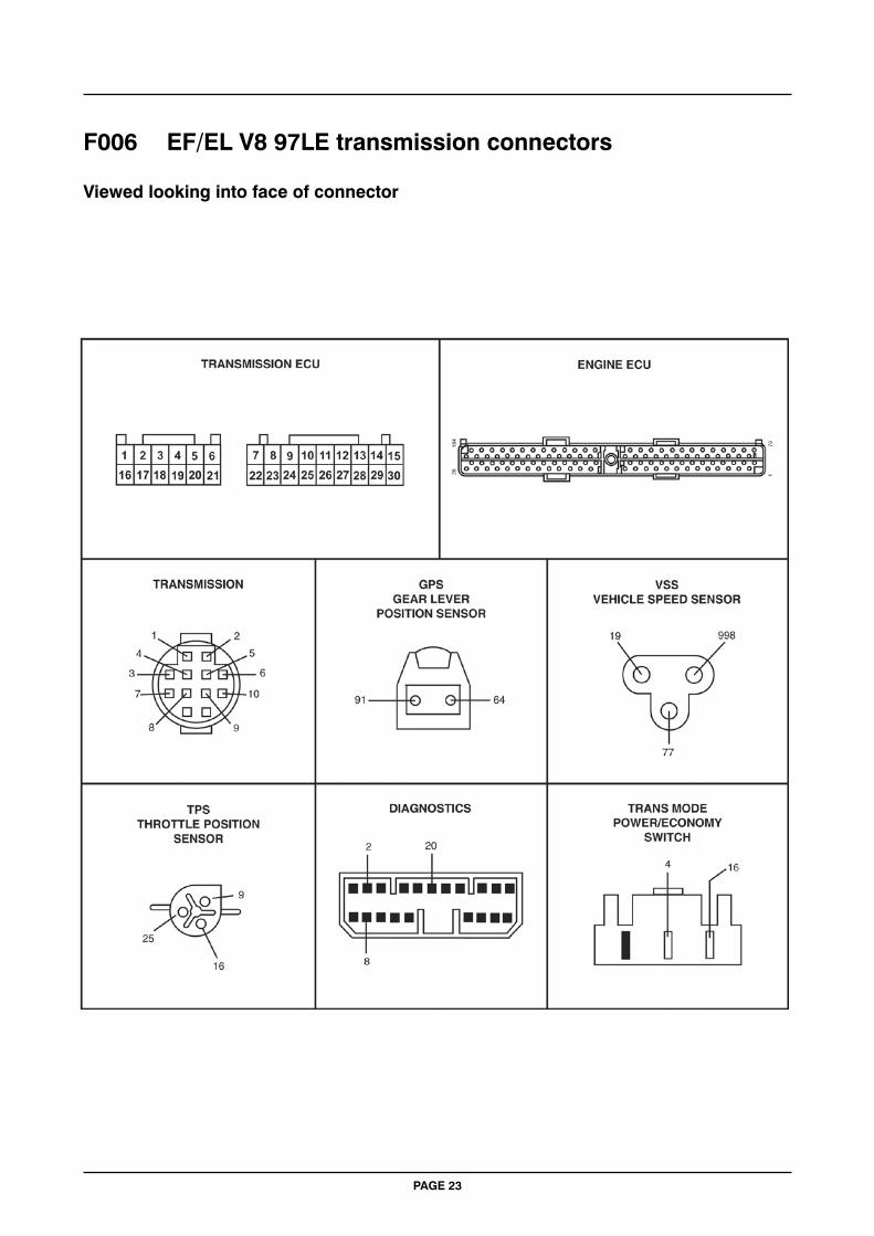
F006 EF/EL V8 97LE transmission connectors
Viewed looking into face of connector
PAGE 24
F007 Upper valve body check ball positions
PAGE 25
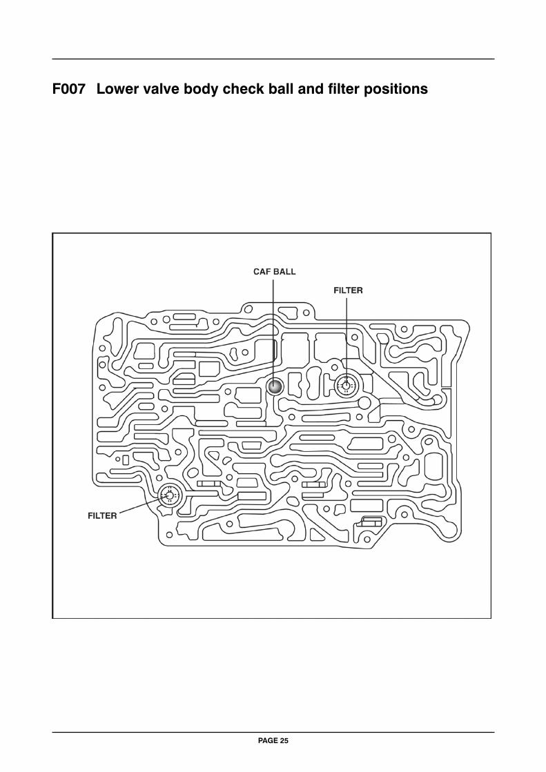
F007 Lower valve body check ball and filter positions
PAGE 26
F008 Front band adjustment EF & EL models only 93LE & 97LE transmissions
PAGE 27
F009 Rear band adjustment EF & EL models only 93LE & 97LE transmissions
PAGE 28
F010 Clutch and band air check supply ports

SNAP-ON TOOLS (AUSTRALIA) PTY LTDABN 55 010 793 683
Form ZATTSFOR92 02/09
E&OE