force sensing and haptic feedback for robotic telesurgery · force sensing and haptic feedback for...
TRANSCRIPT

Project Number: MQP GSF M102
FORCE SENSING AND HAPTIC FEEDBACK FOR ROBOTIC TELESURGERY
A Major Qualifying Project Report:
Submitted to the Faculty
Of the
WORCESTER POLYTECHNIC INSTITUTE
In partial fulfillment of the requirements for the
Degree of Bachelor of Science
By
________________________
________________________
Andrew Marchese
Hubbard Hoyt
Date: April 29th 2010
Approved:
_______________________________
Prof. Gregory S. Fischer, Major Advisor
1. Haptics
2. Robotics
3. Robot-Assisted Surgery

i
TABLE OF CONTENTS
Contents
TABLE OF CONTENTS ............................................................................................................................... i
AUTHORSHIP PAGE ................................................................................................................................ iii
ACKNOWLEDGEMENTS ......................................................................................................................... iv
ABSTRACT ............................................................................................................................................... v
TABLE OF FIGURES ................................................................................................................................. vi
TABLE OF TABLES ................................................................................................................................. viii
1. INTRODUCTION .................................................................................................................................. 1
The General Problem .......................................................................................................................... 1
Overall Goals ...................................................................................................................................... 3
General Procedure ............................................................................................................................. 4
2. LITERATURE REVIEW ........................................................................................................................... 5
Telesurgery ......................................................................................................................................... 5
Haptics and Force Sensing .................................................................................................................. 7
Da Vinci Research ............................................................................................................................... 8
3. PROJECT APPROACH ......................................................................................................................... 10
Initial Client Statement: .................................................................................................................... 10
Objectives and Constraints: .............................................................................................................. 10
Revised Client Statement: ................................................................................................................ 14
4. ALTERNATIVE DESIGNS ..................................................................................................................... 15
Functional Specifications .................................................................................................................. 15
Research Platform ................................................................................................................................ 17
Conceptual Alternatives Generation ................................................................................................ 17
Preliminary Data and Feasibility ....................................................................................................... 19
Sensor Module ..................................................................................................................................... 22
Conceptual Alternatives Generation ................................................................................................ 22
Preliminary Data and Feasibility, Sensor Module ............................................................................ 24
5. FINAL DESIGN METHODOLOGY ........................................................................................................ 25

ii
Overall System Architecture ............................................................................................................. 25
Sensing Element, Amplifiers, and Sensor Module............................................................................ 27
Surgical Tool Actuator ...................................................................................................................... 35
Spherical Wrist ................................................................................................................................. 37
SCARA Robot and Kinematic Models ................................................................................................ 39
Implementation and Synthesis of Robot .......................................................................................... 44
Robot Controller Hardware and Software ....................................................................................... 45
Control System Implementation ...................................................................................................... 49
6. FINAL DESIGN VALIDATION .............................................................................................................. 50
7. DISCUSSION ...................................................................................................................................... 55
8. FUTURE WORK .................................................................................................................................. 57
REFERENCES ......................................................................................................................................... 58

iii
AUTHORSHIP PAGE
Background Research………. Andrew Marchese, Hubbard Hoyt
Design Alternatives………. Andrew Marchese, Hubbard Hoyt
Final Device………. Andrew Marchese, Hubbard Hoyt
Mechanical Design………. Hubbard Hoyt
Mechanical Implementation………. Hubbard Hoyt
Software Design………. Andrew Marchese
Software Implementation………. Andrew Marchese
Electrical Design………. Andrew Marchese
Electrical Implementation………. Andrew Marchese

iv
ACKNOWLEDGEMENTS
We would like to thank Professor Greg Fischer for his unwavering support during this project as well
as committing the resources we needed to make this MQP possible. We would also like to acknowledge
all the support and wisdom from the students at WPI AIM lab and CHSL lab, particularly Ivo Dobrev. The
team would like to thank Professor Yitzhak Mendelson from the Biomedical Engineering Department at
WPI. In addition, we would like to thank the staff and surgeons in the Urology department at Children’s
Hospital in Boston, in particular Dr. Hiep T. Nguyen and Dr. Brian Minnillo. Without their support and
time, we would have not gained such insight on the use and functionality of the da Vinci Surgical Robot.

v
ABSTRACT
Robot-assisted surgery is an alternative to conventional laparoscopic and traditional open surgical
techniques. Currently, the primary commercially available robot-assisted surgical system, the da Vinci
(Intuitive Surgical, Sunnyvale, CA, USA), does not provide haptic feedback to the operator. The goal of
this research was to develop a force sensing module capable of integrating with the da Vinci surgical
system and providing the operator with a representation of end-effecter interaction forces. Additionally,
our aim was to develop a system to serve as a test platform for evaluating and implementing haptic
feedback and telesurgery techniques. Sensors were developed to measure tool joint torques and
calibrated linearly (R2= 0.99). The sensor module was fit to a da Vinci system and physical integration
was successful. An industrial robot was retrofitted with a spherical wrist and an embedded Linux control
system allowing the attached surgical instrumentation to be articulated about a remote center and
emulate da Vinci functionality.

vi
TABLE OF FIGURES FIGURE 1.1: COMPONENTS AND LAYOUT OF MASTER-SLAVE ROBOT-ASSISTED SURGERY. SPECIFICALLY, THE DA VINCI SURGICAL SYSTEM IS
PICTURED (INTUITIVE SURGICAL). .................................................................................................................................. 1
FIGURE 1.3: THE FIRST GOAL OF THE DESIGN PROJECT IS TO DEVELOP A DEVICE TO MEASURE TOOL-TISSUE INTERACTION FORCES FOR THE
PURPOSES OF HAPTIC FEEDBACK. THE GOAL IS FOR THE SENSING MODULE TO FIT BETWEEN AN ACTUAL DA VINCI ARM AND DA VINCI
SURGICAL TOOL.......................................................................................................................................................... 3
FIGURE 2.1: DA VINCI TELEOPERATED SURGICAL SYSTEM. PICTURED AT THE LEFT IS THE MASTER CONTROLLER MANIPULATED BY THE
OPERATOR, TO THE RIGHT IS THE SLAVE ROBOTIC MANIPULATOR (INTUITIVE SURGICAL). ........................................................... 5
FIGURE 2.2: PORTABLE TELEOPERATED SURGICAL ROBOT (BERKELMAN AND MA). .......................................................................... 6
FIGURE 2.4: TRAJECTORY ERROR WHILE RAVEN WAS STATIONED IN LONDON, ENGLAND AND MASTER CONTROLLER WAS STATIONED IN
WASHINGTON (LUM, FRIEDMAN AND SANKARANARAYANAN). ........................................................................................... 7
FIGURE 2.5: SUTURE TENSIONS DURING HAND AND ROBOT SUTURE TIES (OKAMURA). ..................................................................... 8
FIGURE 2.6: ROBOT DEFINITION FOR THE VIRTUAL SIMULATION OF THE DA VINCI USED BY SUN ET AL. (SUN, VAN MEER AND SCHMID) ..... 9
FIGURE 3.1: GENERAL OBJECTIVES LIST AND OBJECTIVES TREE FOR THE SENSING MODULE AND HAPTIC FEEDBACK DEVICE. ..................... 10
FIGURE 3.2: GENERAL OBJECTIVES TREE FOR THE ROBOTIC RESEARCH PLATFORM .......................................................................... 12
FIGURE 4.1: AVERAGE MAXIMUM TENSION DURING SUTURE TIES (OKAMURA). ............................................................................ 15
FIGURE 4.2: CORRESPONDING SURGICAL TOOL JOINT TORQUE RESULTING FROM AVERAGE MAXIMUM SUTURE FORCES. ........................ 15
FIGURE 4.3: FIRST CONCEPTUAL ALTERNATIVE, LABVIEW BASED ROBOT CONTROL SYSTEM. ............................................................. 18
FIGURE 4.4: SECOND CONCEPTUAL ALTERNATIVE, LINUX HIERARCHICAL BASED ROBOT CONTROL SYSTEM. .......................................... 18
FIGURE 4.5: THIRD CONCEPTUAL ALTERNATIVE, MICROCONTROLLER BASED ROBOT CONTROL SYSTEM. .............................................. 19
FIGURE 4.6: VIRTUAL INSTRUMENT USED DURING INITIAL EXPERIMENTS WITH LABVIEW SYSTEM...................................................... 20
FIGURE 4.6: VALIDATION OF RTAI CONTROL PROCESS TIMING. HORIZONTAL AXIS IS SET TO 1 MS/DEV. ............................................. 21
PERIOD BETWEEN CONTROL LOOP EXECUTIONS (TI) IS AT A CONSISTENT 2MS. ............................................................................... 21
FIGURE 4.8: SECOND DESIGN ALTERNATIVE FOR SENSING MODULE. CURRENT THROUGH THE ARMATURE IS MEASURED VIA A CURRENT
SENSE RESISTOR AND THIS CURRENT IS RELATED TO THE TORQUE OUTPUT OF THE MOTOR THROUGH A PHYSICAL CONSTANT
DESCRIBING THE MOTOR’S BEHAVIOR. .......................................................................................................................... 23
FIGURE 4.9: THIRD DESIGN ALTERNATIVE FOR SENSING MODULE CONSISTING OF DEFORMABLE COUPLERS TO MEASURE JOINT TORQUES.
JOINT TORQUES WILL SUBSEQUENTLY BE TRANSLATED TO THE SURGICAL TOOL'S CARTESIAN TIP FORCE VIA A JACOBIAN. ............... 24
FIGURE 5.1: OVERALL FLOW OF SYSTEM ARCHITECTURE INCLUDING MAJOR SUBCOMPONENTS ......................................................... 26
FIGURE 5.2: MATHEMATIC MODEL USED TO DETERMINE PHYSICAL DIMENSIONS OF SENSING ELEMENTS AND RESULTING MAGNITUDE OF
VOLTAGE POTENTIAL. ................................................................................................................................................ 28
FIGURE 5.3: GRADUAL PROPAGATION OF STRESS AND STRAIN RESULTING FROM APPLIED TORQUE (0.6 NM) ABOUT THE AXIS OF ROTATION.
THE MAX DEFLECTION AT MAX TORQUE WAS < 0.02MM.................................................................................................. 29
FIGURE 5.4: ALUMINUM SENSOR ELEMENT WITH FOUR STRAIN GAGES FORMING A FULL ................................................................. 30
WHEATSTONE BRIDGE. THE SENSOR IS 1 INCH IN OUTSIDE DIAMETER. ......................................................................................... 30
FIGURE 5.5: WIRING DIAGRAM FOR INSTRUMENTATION AMPLIFIER CIRCUIT. ONE FOR EACH SENSING ELEMENT WAS NECESSARY. ........... 30
FIGURE 5.6: ACTUAL SIGNAL AMPLIFIER BOARD CONSISTING OF INSTRUMENTATION AMPS (1) ......................................................... 31
LOW PASS FILTER (2) AND TRIM POTENTIOMETERS (3).............................................................................................................. 31
FIGURE 5.7: DESIGN SPACE FOR THE SENSOR MODULE. THE DEVICE MUST INTERFACE WITH DA VINCI ARM FACEPLATE (RIGHT) AND DA
VINCI SURGICAL TOOL (LEFT). ..................................................................................................................................... 32
FIGURE 5.8: DEPICTION OF SENSOR MODULE. TO THE LEFT, AN EXPLODED VIEW OF MODULE AND TO THE RIGHT THE ASSEMBLED MODULE.
............................................................................................................................................................................ 33
FIGURE 5.9: ACTUAL SENSOR MODULE. ................................................................................................................................ 34
FIGURE 5.10: FINAL SURGICAL TOOL ACTUATION MODULE INCLUDING FOUR DC MOTORS, AN INTERFACE TO THE TEAM'S SPHERICAL WRIST
AND TO A STANDARD DA VINCI FACEPLATE. ................................................................................................................... 35

vii
FIGURE 5.12: ILLUSTRATION OF THE FINAL THREE AXES FORMING A SPHERICAL WRIST. TWO OF THESE THREE ..................................... 37
AXES ARE PROVIDED BY THE TEAM'S CUSTOM SPHERICAL JOINT. .................................................................................................. 37
FIGURE 5.13: INSPIRATION FOR THE DESIGN OF THE SPHERICAL WRIST CAME FROM A DEVICE TO EMULATE EYE MOVEMENT. .................. 38
FIGURE 5.14 FINAL DESIGN OF SPHERICAL WRIST USED TO ORIENT DA VINCI SURGICAL TOOL. .......................................................... 38
FIGURE 5.15 ACTUAL IMPLEMENTATION OF SPHERICAL WRIST FINAL DESIGN. ............................................................................... 39
FIGURE 5.16: COORDINATE FRAME DEFINITIONS, ASSUMED OFFSETS, LINK LENGTHS, AND JOINT ANGLE DIRECTIONS FOR THE FULL 6 DOF
ROBOT. .................................................................................................................................................................. 40
FIGURE 5.17: MATLAB SIMULATION OF FORWARD ROBOT KINEMATICS ....................................................................................... 41
FIGURE 5.18: GEOMETRIC LAYOUT OF ROBOT ARM USED INVERSE KINEMATICS ............................................................................. 41
FIGURE 5.20: ARTICULATION OF A TOOL ABOUT A FIXED REMOTE CENTER .................................................................................... 42
FIGURE 5.21: SYNTHESIS OF THE PREVIOUSLY DESCRIBED SUBCOMPONENTS: SONY SCARA INDUSTRIAL ROBOT, SPHERICAL WRIST, TOOL
ACTUATING MODULE, TORQUE SENSING ELEMENTS AND FORCE SENSOR MODULE, AND SURGICAL TOOL. .................................... 44
FIGURE 5.22: LDH-S3 LINEAR AMPLIFIERS USED AMPLIFIER CONTROL SIGNALS AND CONTROL DC MOTORS. FIGURE ADAPTED FROM
WESTERN SERVO DESIGN, CARSON CITY, NV, USA ....................................................................................................... 45
FIGURE 5.23: FLOW OF POSITIONAL DATA FROM ROBOT TO HIGHEST LEVEL CONTROL PROCESS. STEPS INCLUDE QUADRATURE COUNTER
ICS, MICROCONTROLLER, AND EMBEDDED LINUX PROCESSOR. .......................................................................................... 46
FIGURE 5.24: FLOW OF CONTROL PROCESS. THE RESPONSIBILITIES OF THE CONTROL PROCESS AS WELL AS THE PERIPHERALS AND PROCESSES
IT INTERACTS WITH. .................................................................................................................................................. 48
FIGURE 7.1: SENSOR MODULE ON DA VINCI SURGICAL ROBOT AT CHILDREN’S HOSPITAL BOSTON, CONFIRMING DESIGN OBJECTIVE ........ 50
FIGURE 6.2: FURTHER CONFIRMATION OF DEVICE FUNCTIONALITY, THE ARM WAS MOVED WHILE THE SENSOR MODULE WAS ATTACHED. . 50
FIGURE 6.3: TEST RIG USED TO CALIBRATE SENSING ELEMENTS. A MAGNETIC CLUTCH PREVENTED ONE END OF THE SENSOR FROM ROTATING
WHILE A LOAD WAS SYSTEMATICALLY APPLIED TO THE OPPOSITE END. APPLIED TORQUE WAS CALCULATED AND AMPLIFIED VOLTAGE
OUTPUT RECORDED. ................................................................................................................................................. 51
FIGURE 6.4: THE LINEARITY CALIBRATION RESULT FOR 1 OF THE 4 CUSTOM-MADE TORQUE SENSORS THAT COUPLE BETWEEN THE SURGICAL
TOOLS AND THE DA VINCI ROBOT. ................................................................................................................................ 52
FIGURE 6.5: DESIGN VERIFICATION OF ROBOTS ABILITY TO MAINTAIN REMOTE CENTER OF MOTION WHILE INTERPRETING USER INPUT FOR
END EFFECTER POSITIONING. ...................................................................................................................................... 53
FIGURE 6.6: FINAL DESIGN IMPLEMENTATION. A MAJOR OBJECTIVE OF THE PROJECT WAS SUCCESSFUL SYSTEM WIDE INTEGRATION OF THE
RESEARCH PLATFORM ................................................................................................................................................ 54
FIGURE 8.1: DESIRED VS. ACTUAL TRAJECTORY OF ONE OF THE ROBOT'S JOINTS. ........................................................................... 55

viii
TABLE OF TABLES
TABLE 3.1: PAIRWISE COMPARISON CHART USED TO PRIORITIZE OBJECTIVES FOR THE SENSING MODULE AND HAPTIC FEEDBACK DEVICE. IT
WAS DETERMINED THAT EASE OF USE AND COMPATIBILITY WERE THE PRIMARY OBJECTIVES. .................................................... 11
TABLE 3.2: PAIRWISE COMPARISON CHART USED TO PRIORITIZE OBJECTIVES RELATIVELY TO ONE ANOTHER FOR THE ROBOTIC RESEARCH
PLATFORM .............................................................................................................................................................. 12
TABLE 4.1: MORPHOLOGICAL CHART (FUNCTIONS AND POSSIBLE MEANS) FOR THE ROBOTIC RESEARCH PLATFORM. ............................. 17
TABLE 4.2: MORPHOLOGICAL CHART DETAILING MEANS TO ACHIEVE DESIRED PRIMARY FUNCTIONS OF THE SENSOR MODULE ................ 22
TABLE 5.1: CORRESPONDING D-H PARAMETER LIST FOR FULL 6 DOF ROBOT, ALL DIMENSIONS IN MILLIMETERS. ................................ 40

1. INTRODUCTION
The General Problem
Robot-assisted surgery is a minimally invasive surgical technique in which a slave robot is utilized to
manipulate surgical tools. By manipulating a master controller, the surgeon dictates the robot’s
movements and indirectly the surgical tool’s movements. Robot-assisted surgery offers an alternative to
conventional laparoscopic procedures where the surgeon directly controls surgical instruments. The da
Vinci Surgical System (Intuitive Surgical, Sunnyvale, CA, USA) is the primary commercially available
system developed for robot-assisted surgery (Intuitive Surgical). This current system is used extensively
in urological, gynecological, cardiac, and thoracic procedures. Figure 1 illustrates the typical
arrangement of a master-slave robot-assisted surgical system.
There are several advantages that robot-assisted surgery offers when compared to conventional
laparoscopic techniques. The new technique offers increased manipulability and dexterity. The wrist
component of the robot-assisted surgical tool allows the operator to achieve seven degrees-of-freedom
inside the patient. This is a considerable increase from the four degrees-of-freedom offered to the
surgeon during minimally invasive laparoscopic procedures. In the context of ergonomics, conventional
laparoscopic procedures require the surgeon to execute awkward and counterintuitive movements as
the instrument is pivoted about a fulcrum inverting and constraining tool motion. The master-slave
robot-assisted technique allows the operator to intuitively control surgical tool motion. Furthermore,
robot-assisted surgery unarguably enhances procedure visualization when compared to conventional
laparoscopic techniques. The master console allows the surgeon to see the operating field in three
dimensions, restoring the critical element of depth perception found in open surgical techniques
(Mottrie) (Elhage, Murphy and Challacombe).
Master Controller
Surgeon Operator
Slave Robot
Surgical Tool
Wristed Instrument at end of Surgical Tool
Figure 1.1: Components and layout of master-slave robot-assisted surgery. Specifically, the da
Vinci Surgical System is pictured (Intuitive Surgical).

2
Despite the advantages associated with robot-assisted surgery, the technique presents several
disadvantages possibly preventing its assimilation into the operating room and its benefits from being
universally enjoyed. For instance, one primary disadvantage of the da Vinci Surgical System is the
associate surgical costs. Scales et al. found that robot-assisted prostatectomy (RAP) was only
economically competitive with non-robotic radical retropubic prostatectomy (RRP) at high volumes. A
very complex cost model is associated with robot-assisted surgery. Besides the initial cost of the system,
there are several recurring costs such as maintenance ($100,000 per year), disposable surgical tools
($1,500 per tool), operating room time, and length of stay or hospitalization after the procedure.
Because the new procedure’s cost is volume dependent, it may not be economically feasible for small
and non-specialty hospitals (Scales, Jones and Eisenstein).
Furthermore, like any new surgical technique, there is a learning curve associated with robot-
assisted surgery. Canadian researchers Lenihan et al. investigated the learning curve of robot-assisted
surgery, or the time that it took a surgeon to stabilize operation time while using the da Vinci system.
The researchers found the learning curve for performing benign gynecological procedures to be fifty
operations at ninety-five minutes per operation (Lenihan, Kovanda and Seshadri-Kreaden). The speed at
which robot-assisted surgery is incorporated into the operating room may depend on how long it takes
operators to become proficient using the new device.
Perhaps one of the most significant shortcomings of robotic-assisted surgery is the absence of
haptic feedback, or the surgeon’s sensation of tool-interaction forces. Haptic feedback is inherently
present in both conventional laparoscopic and traditional open surgery as the surgeon directly
manipulates the surgical tools and forces are more easily transmitted through the physical connection.
According to Trejos et al., haptic signals can be either kinesthetic, vector forces applied at points or on
Figure 1.2: Depicts the volume dependency of robot-assisted surgery cost. The robotic technique becomes
economically competitive with non-robotic techniques at roughly 10 cases per week (Scales, Jones and Eisenstein).

3
joints, or tactile, textures and distribution of forces. Haptic cues are an important component of surgery
and can enable a surgeon to differentiate tissue, perceive the amount of force applied to tissue, and
generally determine the contour and compliance of tissue (Trejos, Jayende and Perri). Many researchers
agree that the addition of tactile sensation under proper conditions would be a valuable feature in
master-slave robot-assisted surgery (Feller, Lau and Wagner). Tactile feedback typically requires an array
of sensors whereas kinesthetic feedback may require the careful placement of very few sensors.
Not only does the absence of haptic feedback prevent a surgeon from exploring the surgical
field through touch and relying heavily on visual cues, but it limits the information gathered on the
surgical environment. Without a complete picture of the environment, especially tool-tissue interaction
forces, a surgeon’s judgment and intuition maybe impaired. Furthermore, for advances in robot-assisted
procedure where the robot may determine what admissible maneuvers are or apply appropriate safety
constraints, a complete picture of the surgical environment is necessary.
Overall Goals
The goal of this design project is to design a device to provide kinesthetic haptic feedback during
robot-assisted surgery. Ultimately, the team seeks to develop a force sensing module which seamlessly
integrates between a da Vinci surgical tool and the robot’s arm to measure tool-tissue interaction forces
and relay these forces to the operator in an effective manner. Furthermore, this design project aims to
develop a test bed for haptics research. It is desired that the platform emulates the functionality of a da
Vinci arm and articulates a da Vinci surgical tool.
da Vinci Robot Arm
Design Space for Sensor Module
da Vinci Surgical Tool
Figure 1.3: The first goal of the design project is to develop a device to measure tool-tissue interaction forces for the purposes of haptic feedback. The goal is for the
sensing module to fit between an actual da Vinci arm and da Vinci surgical tool.

4
Although the goals of this design project appear to be two separate entities, they are indeed
interdependent. Without an actual da Vinci system, testing, evaluating and refining a sensor module and
haptic feedback device may be extremely difficult. Accordingly, if a research platform is developed in
parallel with the sensing module, the platform can ultimately be used to evaluate the sensing device
independent of the research team’s access to an actual da Vinci Surgical System.
General Procedure
The design team will develop a solution using an iterative approach. The problem will first be
identified as the design team communicates and exchanges ideas with both users of the device and
clients. Once design objectives and constraints are identified, design alternatives will be proposed that
meet the required system functionality previously specified in the problem statement. Conceptual
alternatives will be evaluated against matrices and each design’s feasibility of implementation will be
evaluated. A final design of the device will be selected and constructed. The device’s functionality will be
verified. Future considerations and recommendations will be communicated.
This document is divided into chapters detailing the design team’s work. The next chapter, the
literature review, is intended to inform the reader of what is currently known about the problem the
team is attempting to solve as well as construct a logical foundation for the approach the design team
took in surmounting the challenge. Subsequently, the project strategy will present specifically the
problem the team is attempting to solve and describe the challenge in terms of objectives and
constraints. The alternative designs section will detail the necessary functions of the device and possible
means. These lead to the development of our conceptual design alternatives, feasibility studies,
implemented alternative designs, and experiments. The design verification chapter includes our
methodology in developing our final design and the results of each component of our final design. In the
discussion, the design team reflects on the resulting design in the context of existing research within the
field. We determine the validity of assumptions made throughout the design processes, the limitations
of our designs, and convince the reader that the design did indeed meet the objectives and constraints
laid out before. The final design validation chapter provides a more detailed look at the final design and
is written for an audience looking to continue the project work.

5
2. LITERATURE REVIEW
Telesurgery
Recently, there have been significant advances in telesurgery research. As Haidegger et al.
(Haidegger, Benyo and Kovacs) mentions, the da Vinci surgical system is the most successful master-
slave surgical system to date. Currently, the master system relays control signals to the slave system
based on user input. The user decides where to position the robot based on visual feedback. Haidegger
et al. suggest haptic feedback in addition to visual feedback could be very advantageous during the
manipulation of telesurgical systems.
Figure 2.1: Da Vinci Teleoperated Surgical System. Pictured at the left is the master controller manipulated by the
operator, to the right is the slave robotic manipulator (Intuitive Surgical).
Berkelman and Ma (Berkelman and Ma) demonstrated that the physical footprint, weight and
complexity of surgical robots can be drastically reduced while still allowing the robot to be just as, if not
more, advantageous than their more cumbersome counterparts. These authors devised a robotic
system which manipulates customized laparoscopic instruments allowing the robotic system to maintain
the benefits of laparoscopic procedures such as being minimally invasive, reducing patient recovery
time, and enhancing operator dexterity and visualization. However, their system is advantageous
because it can be teleoperated by a surgeon some distance away and is small and lightweight enough to
be mounted on a surgical table. Additionally, as the authors conclude, the small size of the robot
enables lower actuating torque than traditional more massive surgical robots making this teleoperated
robot inherently safer. Figure 2.2 illustrates the surgical robot Berkelman and Ma developed. Figure 2.3
depicts the increased precision associated with the researcher’s teleoperated system over conventional
laparoscopic manipulation.

6
Figure 2.2: Portable teleoperated surgical robot (Berkelman and Ma).
Figure 2.3: Berkelman and Ma demonstrated that their robot offers increased precision when compare to conventional
laparoscopic manipulation (Berkelman and Ma).
Researchers at the University of Washington (Lum, Friedman and Sankaranarayanan) have
demonstrated significant advancements in teleoperated robot research. Lum et al. developed the
RAVEN, which is a master-slave telesurgical system. The robot utilizes two spherical manipulators which
easily manipulate surgical instruments about a remote center. However, perhaps the most intriguing
component of this research is the robot’s teleoperation capabilities. For instance, the RAVEN (slave
component of the surgical system) was deployed in Simi Valley, CA while the master surgeon console
remained in Seattle, WA. Experiments were conducted and it was found that surgical maneuvers could
be successfully accomplished given the communication latency. This mobile experiment yielded

7
communication latencies of roughly 16 ms. These researchers also performed experiments with the
RAVEN located in London, England and observed communication latencies averaging 75 ms. Figure 2.4
depicts the trajectory error due to communication latency observed by the researchers. It is also notable
that an RTAI control system was used in developing the RAVEN.
Figure 2.4: Trajectory error while RAVEN was stationed in London, England and master controller was stationed in
Washington (Lum, Friedman and Sankaranarayanan).
Haptics and Force Sensing
Many researchers acknowledge the potential benefits of force feedback for robotic surgical tools.
For instance, Ishii et al. recently developed a novel robotic forceps bending-manipulator (Ishii, Kobayashi
and Kamei). The researchers envision their device easily relaying force feedback information to the
operator during surgery. The desired ability for robotically manipulated surgical utensils to provide force
feedback is an increasing trend.
Okamura (Okamura) explains that most commercially available telerobotic systems do not
incorporate haptic feedback. The author provides motivation for haptics research including the ability
for haptic feedback to enhance surgical simulation and better train practitioners. Additionally, with
haptic feedback it may be possible to emulate tissue and potentially operate on a virtually still biological
system.
Okamura conducted a very practical experiment to demonstrate how easy it is for cardiac surgeons
to break fine sutures during robot-assisted surgery with no force feedback. Suture tensions were
measured during knot tying. It was shown that suture tension was much higher when a robotic
instrument was used to tie the suture compared to when the suture was tied by hand. Clearly force
feedback would be a very practical and logical progression in robot-assisted surgery. Figure 2.5
illustrates Okamura’s experimental results.

8
Figure 2.5: Suture tensions during hand and robot suture ties (Okamura).
Research into the proper use and benefits of haptic feedback is necessary for the successful
implementation of haptic feedback devices. Researchers at Johns Hopkins (Verner and Okamura)
investigate the influence of additional haptic feedback degrees of freedom and whether or not they are
necessary. The researchers explain how little research exists on whether complex feedback tasks
incorporating both torques and Cartesian forces can be simplified into mere force feedback tasks. If
properly understood, simplifications in feedback systems may lower costs, complexity, and the time it
takes to successfully implement a force feedback system. Researchers found that during simple tasks
force feedback can indeed be simplified and not impair usefulness. Specifically, force and torque
feedback can be simplified into solely force feedback without observing significant performance
differences in the simple task of drawing a circle.
Mahvash and Okamura (Mahvash and Okamura) have also conducted considerable research in
minimizing the unwanted effects of the mechanical telesurgical system (friction and inertia) on force
feedback. This optimization increases the clarity of force transmission between the slave to master
components of system.
Da Vinci Research
Several groups have attempted to recreate the da Vinci’s functionality. For instance, Sun et al. (Sun,
Van Meer and Schmid) developed a software simulation of the da Vinci system for the purpose of
surgical training. Their simulation modeled the surgical robot’s 13 degrees-of-freedom. The simulation is
controlled by two SensAble Phantom Omni devices fitted with custom finger grippers. The intent of the
research is to facilitate da Vinci training, allowing an operator to experience a virtual system with
identical functionality to the da Vinci. They envision their system reducing the da Vinci learning curve
and being used to optimize trocar placement for surgical planning.

9
Figure 2.6: Robot definition for the virtual simulation of the da Vinci used by Sun et al. (Sun, Van Meer and Schmid)
10
3. PROJECT APPROACH
Initial Client Statement:
“Design a device to measure tool-tissue interaction forces during robot-assisted surgery and
effectively relay these forces to the operator. Furthermore, develop a custom platform to articulate a da
Vinci tool, emulating the functionality of the surgical robot.”
As the reader can see, this initial client statement was not specific enough to yield an appropriate
design. Further communication with our advisor and users of the device was necessary. The design team
had the opportunity to discuss the idea of a force sensing module and custom platform for haptics
research with Dr. Hiep T. Nguyen, the Director of Robotic Surgery Research and Training at Children’s
Hospital Boston.
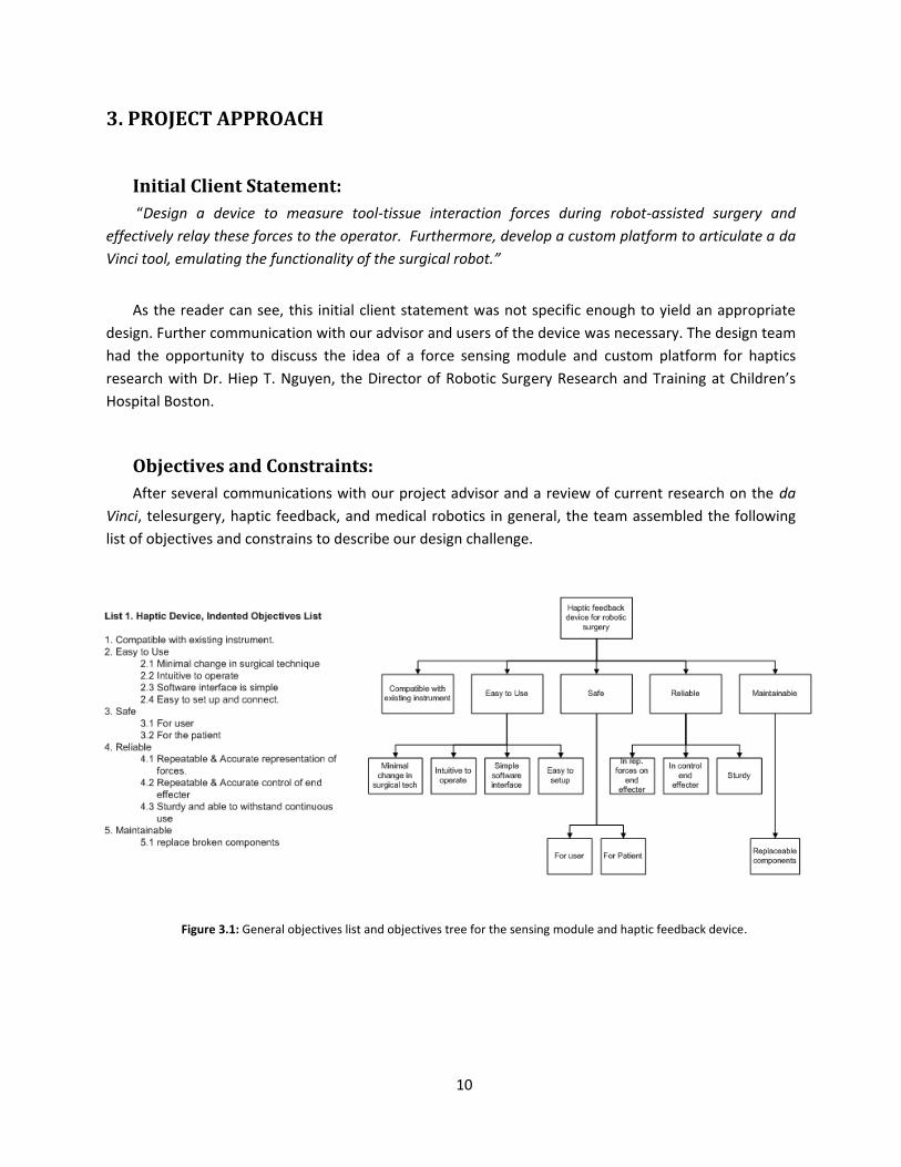
Objectives and Constraints:
After several communications with our project advisor and a review of current research on the da
Vinci, telesurgery, haptic feedback, and medical robotics in general, the team assembled the following
list of objectives and constrains to describe our design challenge.
Figure 3.1: General objectives list and objectives tree for the sensing module and haptic feedback device.

11
Once these objectives were initialized, the design team sought a way to elicit from our advisor the
most important objectives. Although all seemed important, the objectives needed to be prioritized.
Accordingly, a pairwise comparison chart was used to weight the objectives and determine the priority
of objectives relative to each other.
Table 3.1: Pairwise comparison chart used to prioritize objectives for the sensing module and haptic feedback device. It was determined that ease of use and compatibility were the primary objectives.
General Goals Compatibility Easy to Use Safe Reliable Maintainable Score
Compatibility ••• 0.5 0.5 1 1 3
Easy to Use 0.5 ••• 1 1 1 3.5
Safe 0.5 0 ••• 1 1 2.5
Reliable 0 0 0 ••• 0.5 0.5
Maintainable 0 0 0 0.5 ••• 0.5
The same process was repeated for the robotic research platform. Initially we brainstormed a
list of objectives and subsequently attempted to narrow and prioritize the objectives through the use of
pairwise comparison charts.

12
Again, after a thorough list of objectives was created, we sought feedback from our advisor and by
referring to literature in order to prioritize the objectives.
Table 3.2: Pairwise comparison chart used to prioritize objectives relative to one another for the robotic research platform
General
Goals
Reproducible and
Accurate Expandable User Friendly inexpensive simple Score
Reproducible and
Accurate ••• 1 0 1 0.5 2.5
Expandable 0 ••• 0 1 1 2
User Friendly 1 1 ••• 1 1 4
inexpensive 0 0 0 ••• 0 0
simple 0.5 0 0 1 ••• 1.5
Overall, the high priority objectives for the project can be resolved into a concise list. This list
was what the design team used to plan our conceptual designs in the next section.
Figure 3.2: General objectives tree for the robotic research platform

13
List 3.1: Primary design objectives for the two primary subcomponents.
1. The force sensing module and haptic feedback device:
Reliable sensing: The sensor module should reliably and accurately measure forces
applied to the end effecter of the da Vinci surgical tool.
Effective: Sensor data must be mapped to end effecter forces and this kinesthetic haptic
feedback should be effectively represented to the operator.
Compatibility: The sensor module should attach between the surgical tool and standard
da Vinci positioning arm.
2. The robotic research platform:
User Friendly Control: A dynamic Cartesian position and static remote center should be
easily input by the user.
Reproducible positioning: The platform should allow the surgical tool to be reproducibly
positioned in real-time.
Next, the design needed to be realistically constrained from a variety of areas including spatial,
financial, time, safety, and resources. A concise list of constraints was developed for each of the two
major subcomponents before moving forward in the design process.
List 3.2: Design constraints for the two primary subcomponents.
1. The force sensing module and haptic feedback device must. . .
Constraint: Must not fall apart during simulated surgery
Constraint: Must not inhibit surgical procedure
Constraint: Prototype must not cost more than $300
Constraint: Must interface with standard da Vinci surgical tool and da Vinci arm
Constraint: Must be constructed from resources available through WPI
2. The robotic research platform must. . .
Constraint: Must fit on laboratory work bench
Constraint: Must build open existing industrial pick-and-place robot
Constraint: Prototype must not cost more than $300
Constraint: Must be safe and have emergency stop
Constraint: Must be constructed from resources available through WPI
Moreover, the design team spent considerable time determining what the device must actually
do, or its functions. This step consisted of treating each subcomponent of the design as a figurative black
box. Given a set of inputs and desired outputs, what must the device do to achieve appropriate mapping
of inputs to outputs.

14
List 3.3: Functional requirements of the two major subcomponents
1. The force sensing module and haptic feedback will. . .
Function: Measure applied forces to end effecter of da Vinci surgical tool
Function: Measure position of end effecter
Function: Transmit force and positional data to the controller
Function: Actuate da Vinci tool based on positional information
Function: Transmit force data to the operator
2. The robotic research platform will. . .
Function: Articulate the da Vinci surgical tool with approximately the same degrees-of-
freedom as Intuitive’s da Vinci Surgical System.
a. Sense positional data from axes of the robotic platform
b. Generate and amplify command signals to actual robotic platform
Function: Interpret desired command position from user’s physical input and scale
Function: Hold an arbitrary point along the tool shaft still to simulate tool-skin interface
(remote center of motion).
Function: Allow the user to calibrate and zero the platform.
With the design space more thoroughly explored and subsequently constrained, it was possible
for the design team to revise our client statement. Our objective with the revised client statement was
to articulate exactly what was expected from the design while keeping the description as concise as
possible.
Revised Client Statement:
“Design a modular device to reliably measure tool-tissue interaction forces during robot-assisted
surgery and effectively relay these forces to the operator. The device should be constructed for under
$300 and integrate with the da Vinci Surgical System (preferably between the surgical tool and arm as to
not inhibit the surgical procedure). Furthermore, develop a custom platform to articulate a da Vinci tool
with the degrees-of-freedom of an actual da Vinci robot, while maintaining a remote center of motion.
The platform should reliably control the position of the tool and easily translate the user’s physical input
into tool motion.”

15
4. ALTERNATIVE DESIGNS
Functional Specifications
Before the design team could conceptualize design alternatives, it was important to add specific
values in order to quantify the listed device functionality. The most critical objective of this step in the
design process was to identify the range of operation components should operate within. These
specifications may be wrong, however since the design is methodical, they can easily be changed and
the process repeated yielding a slightly modified design.
List 4.1: Design specifications associated with design functionalities
1. The force sensing module and haptic feedback device
Spec: Measure applied forces to end effecter of da Vinci surgical tool which range from
approximately 0.25 to 6 Newtons during typical suturing maneuvers (Okamura). The
design team then calculated corresponding maximum joint torques at the tool interface
(TJoint) to be roughly 0.2 Nm.
Figure 4.1: Average maximum tension during suture ties (Okamura).
Figure 4.2: Corresponding surgical tool joint torque resulting from average maximum suture forces.
FTip = 6 N
LTip = 0.02m R1 = 0.002m
R2 = 0.003m TJoint
FTip
TJoint

16
Spec: Measure position of end effecter via joint rotations with an error of at maximum
±0.7 degrees. This is the resolution a 500 count per revolution encoder will measure
rotational motion in a joint.
Spec: Transmit force and positional data to the controller at a rate between 0.5 and 1.0
Khz. This is the industry standard for control loop execution.
2. The robotic research platform
Spec: Articulate the da Vinci surgical tool with 6 degrees-of-freedom, 3 positional and 3
orientation (Sun, Van Meer and Schmid).
a. Sense positional data from axes of the robotic platform with an error of at
maximum ±0.7 degrees. This is the resolution a 500 count per revolution
encoder will measure rotational motion in a joint.
b. Generate and amplify command signals to actual robotic platform. 6 signals
(one for each necessary joint actuator) should saturate at -12 and +12 volts (bi-
directional control) and supply 2 amps continuous and 3 to 4 amps peak. (to
overcome frictional and inertial torques at each joint while linearly accelerating
to a peak velocity of 0.6 radians per second). This information was determined
empirically from the industrial pick-and-place robot.
Spec: Hold an arbitrary point along the tool shaft still to simulate tool-skin interface
(remote center of motion). Should appear visually still and remote center should move
with a maximum error of ±5mm (tolerable skin stretch).
17
Research Platform
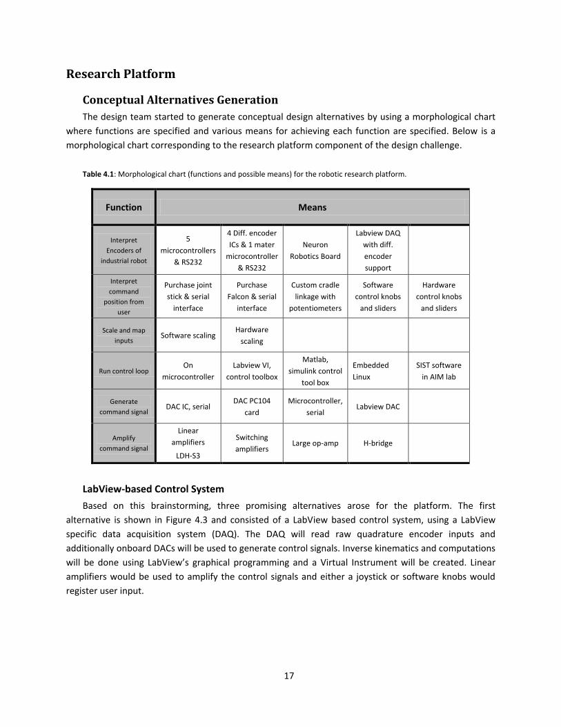
Conceptual Alternatives Generation
The design team started to generate conceptual design alternatives by using a morphological chart
where functions are specified and various means for achieving each function are specified. Below is a
morphological chart corresponding to the research platform component of the design challenge.
Table 4.1: Morphological chart (functions and possible means) for the robotic research platform.
Function Means
Interpret
Encoders of
industrial robot
5
microcontrollers
& RS232
4 Diff. encoder
ICs & 1 mater
microcontroller
& RS232
Neuron
Robotics Board
Labview DAQ
with diff.
encoder
support
Interpret
command
position from
user
Purchase joint
stick & serial
interface
Purchase
Falcon & serial
interface
Custom cradle
linkage with
potentiometers
Software
control knobs
and sliders
Hardware
control knobs
and sliders
Scale and map
inputs Software scaling
Hardware
scaling
Run control loop On
microcontroller
Labview VI,
control toolbox
Matlab,
simulink control
tool box
Embedded
Linux
SIST software
in AIM lab
Generate
command signal DAC IC, serial
DAC PC104
card
Microcontroller,
serial Labview DAC
Amplify
command signal
Linear
amplifiers
LDH-S3
Switching
amplifiers Large op-amp H-bridge
LabView-based Control System
Based on this brainstorming, three promising alternatives arose for the platform. The first
alternative is shown in Figure 4.3 and consisted of a LabView based control system, using a LabView
specific data acquisition system (DAQ). The DAQ will read raw quadrature encoder inputs and
additionally onboard DACs will be used to generate control signals. Inverse kinematics and computations
will be done using LabView’s graphical programming and a Virtual Instrument will be created. Linear
amplifiers would be used to amplify the control signals and either a joystick or software knobs would
register user input.

18
Figure 4.3: First conceptual alternative, LabView based robot control system.
Linux-based Control System
A second design alternative depicted in Figure 4.4 consisted of a Linux based control system. Here,
raw encoder output would first be processed by purchased integrated circuits specifically intended to
input quadrature signals and output a 16-bit count via serial communication. A low level microcontroller
would be in charge of requesting positional data from each counter IC. The low level microcontroller
would then communicate via serial to an embedded Linux computer, which would execute high level
processing and generate control signals. A PC104 card with DACs would be used to output control
signals to a series of linear amplifiers controlling the robot’s DC motors.
Figure 4.4: Second conceptual alternative, Linux hierarchical based robot control system.
Microcontroller Control System
The final alternative design illustrated in Figure 4.5 consisted of moving the entire control system to
an embedded microcontroller. The alternative consists of using an 80Mhz PIC microcontroller. On board
external interrupts will be utilized to count quadrature encoder pulses, and on board DACs will be
utilized to output command signals. Internal clocks will be used to generate an interrupt driven control
loop to compute joint positions from user input utilizing robot kinematics. As in the above alternatives,
LabView
DAQ
Linear
Amplifiers
Raw
Encoder
Output
Labview
Virtual
Instrument
SCARA
Industrial
Robot
(3 DOF)
Spherical
Wrist
(3 DOF)
Surgical
Tool
User Input
(Knob or slider)
SCARA
Industrial
Robot
(3 DOF)
Spherical
Wrist
(3 DOF)
Surgical
Tool
Linear
Amplifiers
DACs on
PC104 card
Quadrature
Encoder ICs
Single
Atmega644P
Embedded
Linux
Computer
Falcon Input
Device

19
linear amplifiers are employed to amplify control signals. User input can take the form of hardware
knobs and sliders or a possible falcon controller.
Figure 4.5: Third conceptual alternative, Microcontroller based robot control system.
Preliminary Data and Feasibility
The design team began to look at the alternative da Vinci research platforms critically and
determine which alternative was indeed feasible and could meet the outlined design objectives. We
began by evaluated the LabView based control system. A simple serial communication Virtual
Instrument example was used to evaluate the real-time capabilities of LabView running in a Windows
environment without specialized real-time hardware such as National Instrument’s cRIO. The provided
default serial communication instrument was slightly modified. From this initial experiment, the design
team concluded that a reliable 1 ms control loop could not be established. The tested loop wrote a
request character to a low level AVR microcontroller and subsequently read several bytes transmitted
from the microcontroller, and finally cleared the serial buffer.
SCARA
Industrial
Robot
(3 DOF)
Spherical
Wrist
(3 DOF)
Surgical
Tool Linear
Amplifiers
80Mhz PIC
microcontroller
External
Interrupts
DACs
SPI bus UART
User Input
Peripheral

20
Figure 4.6: Virtual Instrument used during initial experiments with LabView system.
Given these results, the design team concluded that this alternative was not feasible. A clear design
object was for the platform to reliably run a 0.5 to 1 Khz control loop.
Looking for a real-time solution, the design team next evaluated the possibility of moving the
control system to a single microcontroller, design alternative three. Using the PIC microcontroller in
conjunction with an external 80Mhz oscillator, a reliable 1Khz interrupt could easily be achieved. The
inverse kinematics calculations required to determine the robot’s joint angles and the collection of
sensor input through both analog to digital converters and serial communication could, with
conservative fixed point mathematics, be moved to the microcontroller. The major disadvantage to this
alternative is the lack of processing downtime. In terms of usability and user interface, having a PC and
monitor would be much more familiar and friendlier. For the reasons of simple user interfacing, the
design team chose to reject this design alternative.
The Linux based control system, shown in Figure 4.4, was chosen for the robotics research
platform. This alternative was the only alternative that met the functional specifications of being able to
reliably produce a 0.5 to 1 Khz real-time control loop, allow easy interfacing with the user and more
complicated peripheral devices as well as easily handle the magnitude of calculations, sensor reading,
and serial communication necessary for the research platform.

21
To validate this alternative a vanilla Linux kernel (version 2.6.28.7) was patched with RTAI (version
3.6.1) and re-complied on Ubuntu 8.10. The real-time kernel provides a hardware abstraction layer
(HAL) enabling reliable microsecond timing under a Linux operating system. Through considerable time
and efforts, the installation of RTAI and the recompilation of the kernel were achieved (please see final
design for a more detailed explanation). Ultimately, the design team was able to run a simple control
process in real-time at 500 Hz. Timing was confirmed by modulating a digital IO pin during and observing
the output on an oscilloscope. In the final system, the timing was set to 1kHz.
Figure 4.6: Validation of RTAI control process timing. Horizontal axis is set to 1 ms/dev.
Period between control loop executions (Ti) is at a consistent 2ms.
Ti

22
Sensor Module
Conceptual Alternatives Generation
The design team brainstormed several effective ways to measure and relay forces and positional
data as well as actuate the da Vinci Surgical tool. Again, the team resorted to constructing a
morphological chart to organize potential conceptual alternatives. Here, a variety of means for achieving
each of the subcomponent’s primary functionalities were outlined.
Table 4.2: Morphological chart detailing means to achieve desired primary functions of the sensor module
Function Means
Measure
kinesthetic bulk
forces on end
effecter
Force sensor
(pad) applied to
points of tissue
contact
Measure tool
joint torques
with custom
torque sensor
Measure tool
joint torques
with current
sensing
Measure and
actuate wrist of
surgical tool
Closed loop:
Encoders and
small DC motors
Open loop:
small stepper
motor
Transmit Haptic
forces to user
Falcon Haptic
Device Custom cradle
Phantom Haptic
Device
Force Sensing Pads
Several alternatives were formulated. The first of these alternatives was to utilize circular force
sensing pads placed on critical tool-tissue interaction points. These sensors’ signals will be amplified and
relayed to the central processor. The surgical tool will be actuated by a set of DC motors with shaft
encoders to measure position. Figure 4.7 shows a conceptual sketch of this alternative.
Figure 4.7: First design alternative for sensing module. Force pads placed on critically tool-tissue interaction locations
monitor tool tip forces. An amplifier board is used to condition the signals.
Force
Sensing
Pads
Amp
Module Surgical
tool
Joint
Gripper

23
Current Sensing
Secondly, the design team envisioned using a current sense resistor to measure applied motor
torque on each of the four surgical tool joints. The alternative is illustrated in Figure 4.8 and is adapted
from a concept found in a recent publication (Mahvash and Okamura). This alternative requires having a
rough model of the DC motors used to actuate the tool in order to understand the relationship between
current through the armature and applied motor torque (typically a constant, KT). The motor, modeled
as a resistor, inductor, and voltage source in series, has the same current (Iarmature) passing through all its
components. Another resistor, Rsense, is added in series. If the voltage differential over the current sense
resistor is measured, via an instrumentation amplifier, and the resistance value is known, then the
current in the series circuit is easily determined. Joint torques will be related to end-effecter Cartesian
forces by empirically determining a Jacobian matrix describing the surgical tool. The method used to
actuate and measure tool position is the same as in the previous alternative.
Figure 4.8: Second design alternative for sensing module. Current through the armature is measured via a current sense resistor and this current is related to the torque output of the motor through a physical constant describing the motor’s
behavior.
Custom Torque Sensor
Thirdly, the design team developed an alternative based on custom torque sensors to measure joint
torques directly. This alternative is illustrated in Figure 4.9. Each sensor is meant to act as a coupler
between the actuating motor and da Vinci surgical tool control surface. The coupler will be engineered
such that it intentionally elastically deforms under rotational torque. The deformation in the material
will be measured by strain gages. The gages will be assembled in a full bridge arrangement such that
under mechanical load the bridge will become unbalanced. An instrumentation amplifier will be used to
capture this voltage differential. Below are conceptual designs the team created of couplers meant to
deform elastically under applied torque.
Instrumentation
Amplifier
Rsense
Vdifferential
Vterminal
Iarmature
Tjoint

24
Figure 4.9: Third design alternative for sensing module consisting of deformable couplers to measure joint torques. Joint
torques will subsequently be translated to the surgical tool's Cartesian tip force via a Jacobian.
Preliminary Data and Feasibility, Sensor Module
The team heavily considered the constraints and objectives of the project while evaluating the
feasibility of alternatives. For example, the first alternative, placing force sensing pads at tool-tissue
interaction points, requires considerable modification to the da Vinci surgical tool and a major objective
of the project is for the device to easily integrate into and work with the existing surgical system. The
fact that this alternative requires each tool to be individually modified is unacceptable from the
perspective of compatibility.
Additionally, the current sensing alternative offered a very compact, reliable solution. This
alternative does not seem to spatially interfere with the surgical procedure and requires minimal
moving components adding to safety and reliability. However, the primary problem the design team saw
in this alternative was that the da Vinci motors are not accessible to the user and the addition of a
sensing resistor would require modification to the existing equipment. This directly contradicts the
team’s design constraints making this alternative infeasible.
The best alternative that the design team conjured was a module containing four external
joint torque sensors, as are depicted in Figure 4.9. The module is intended to integrate between the da
Vinci surgical tool and the da Vinci arm faceplate. This design would not require any modification to the
existing device. The seamless integration of this alternative offered with existing technology seemed to
outweigh the challenge presented in creating its torque sensing elements. For these reasons, this
alternative was chosen.
Axis of Rotation
Potential
Strain Gage
Locations
25
5. FINAL DESIGN METHODOLOGY
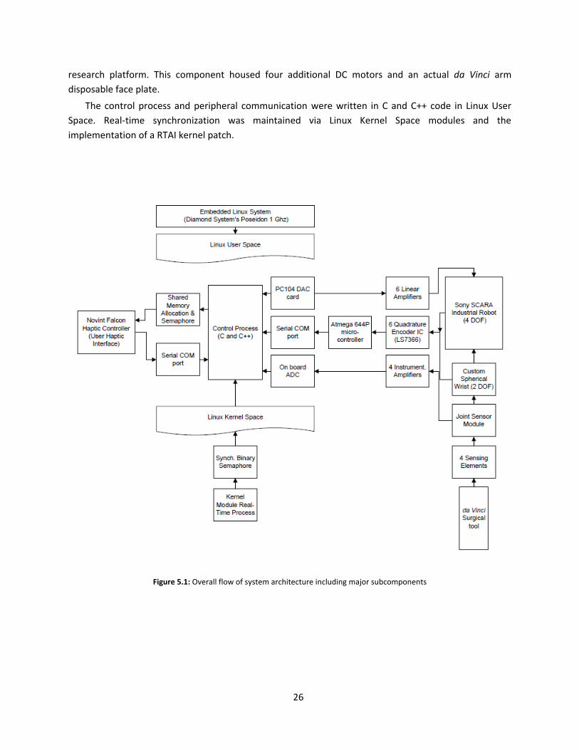
Overall System Architecture
The overall system contained mechanical, electrical, and software subsystems. Figure 5.1 illustrates
the overall final design. The proper integration of these subsystems yielded the design’s functional
requirements outlined in the previous sections. The team developed the following major
subcomponents:
Custom Spherical Wrist
Surgical Tool Actuator Module
Sensing Elements, Signal Amplifiers, and Sensor Module
Electronics for Control System
Software for Control System
Haptic User Interface
The design was centered on the use of a Sony SCARA industrial robot acquired previously by the
research laboratory. The robot offered 4 independent degrees-of-freedom. In accordance with the
team’s design objectives, 2 additional degrees of freedom were necessary to specify the surgical tool’s
orientation and maintain a remote center of motion. To achieve this functionality, a custom 2 degree-of-
freedom spherical wrist was designed and implemented. In order to measure tool-tissue interaction
forces, a sensing module capable of measuring surgical tool joint torques was employed. This module’s
main feature is its capacity to mount seamlessly in-between the da Vinci surgical tool and arm,
emulating both male and female da Vinci connections on the corresponding faces of the module. This
module housed 4 sensing elements, intended to elastically deform under torque. Strain gages arranged
in a full-bridge converted this mechanical disturbance into a potential difference. The voltage
differential was amplified using 4 instrumentation amplifiers and sampled using 4 analog to digital
converters present on the embedded single board PC. These torques were mapped to end-effecter tip
forces in the control process and output to the haptic user interface.
The robot was actuated based on the user’s desired position input. This was acquired at the haptic
user interface. The 6 degree-of-freedom robot’s inverse kinematics were utilized in the control process
to determine corresponding joint angles from the user’s desired Cartesian end-effecter position. PID
controllers were used at each joint to control joint angles. As mentioned, the set values for the
controllers came from the results of inverse kinematic calculations. The actual position was measured
using rotary encoders at each joint. Quadrature counter integrated circuits were utilized to count
quadrature signals coming from the encoders and a single Atmega microcontroller was used to request
positional information from each of the 6 joints. Communicating through a serial port, the high level
embedded Linux control process requests all positional information from the low level Atmega
microcontroller.
Resulting control signals were output through digital to analog converts on a PC104 card.
Subsequently, command signals were amplified using moderately high-current linear amplifiers and sent
to the robot’s 6 DC motors. Lastly, a module capable of actuating the surgical tool was necessary for the
26
research platform. This component housed four additional DC motors and an actual da Vinci arm
disposable face plate.
The control process and peripheral communication were written in C and C++ code in Linux User
Space. Real-time synchronization was maintained via Linux Kernel Space modules and the
implementation of a RTAI kernel patch.
Figure 5.1: Overall flow of system architecture including major subcomponents
27
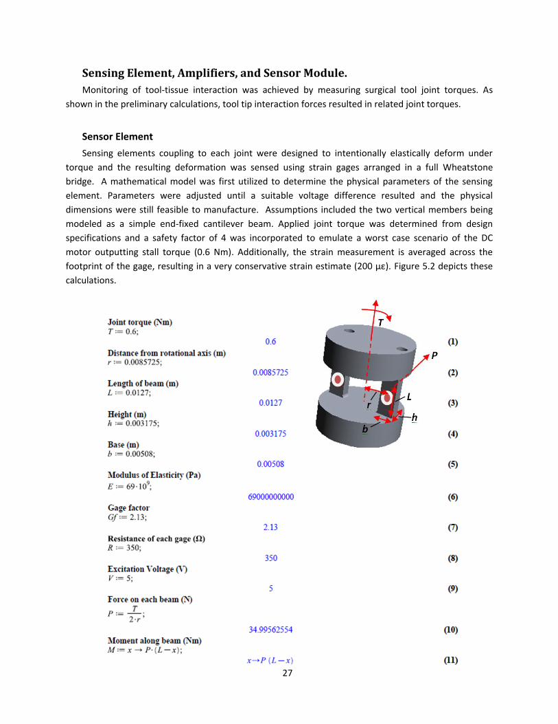
Sensing Element, Amplifiers, and Sensor Module.
Monitoring of tool-tissue interaction was achieved by measuring surgical tool joint torques. As
shown in the preliminary calculations, tool tip interaction forces resulted in related joint torques.
Sensor Element
Sensing elements coupling to each joint were designed to intentionally elastically deform under
torque and the resulting deformation was sensed using strain gages arranged in a full Wheatstone
bridge. A mathematical model was first utilized to determine the physical parameters of the sensing
element. Parameters were adjusted until a suitable voltage difference resulted and the physical
dimensions were still feasible to manufacture. Assumptions included the two vertical members being
modeled as a simple end-fixed cantilever beam. Applied joint torque was determined from design
specifications and a safety factor of 4 was incorporated to emulate a worst case scenario of the DC
motor outputting stall torque (0.6 Nm). Additionally, the strain measurement is averaged across the
footprint of the gage, resulting in a very conservative strain estimate (200 µε). Figure 5.2 depicts these
calculations.

28
Subsequently, the team used finite element modeling in SolidWorks (SolidWorks Corp., Concord,
MA, USA) to confirm the mathematical model and optimize the placement of strain gages on the
bending cantilever-like beams of the sensor element. Figure 5.3 details the finite element modeling.
Figure 5.2: Mathematic model used to determine physical dimensions of sensing elements and resulting magnitude of voltage potential.

29
The actual sensor elements were machined from 1 inch precision ground 6061 aluminum on a
manual Bridgeport machine. All critical dimensions were confirmed to have tolerances within ±0.005
Figure 5.3: Gradual propagation of stress and strain resulting from applied torque (0.6 Nm) about the axis of rotation. The max deflection at max torque was < 0.02mm.
30
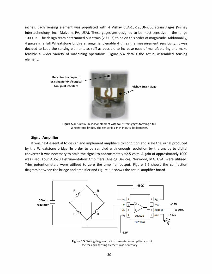
inches. Each sensing element was populated with 4 Vishay CEA-13-125UN-350 strain gages (Vishay
Intertechnology, Inc., Malvern, PA, USA). These gages are designed to be most sensitive in the range
1000 µε. The design team determined our strain (200 µε) to be on this order of magnitude. Additionally,
4 gages in a full Wheatstone bridge arrangement enable 4 times the measurement sensitivity. It was
decided to keep the sensing elements as stiff as possible to increase ease of manufacturing and make
feasible a wider variety of machining operations. Figure 5.4 details the actual assembled sensing
element.
Figure 5.4: Aluminum sensor element with four strain gages forming a full
Wheatstone bridge. The sensor is 1 inch in outside diameter.
Signal Amplifier
It was next essential to design and implement amplifiers to condition and scale the signal produced
by the Wheatstone bridge. In order to be sampled with enough resolution by the analog to digital
converter it was necessary to scale the signal to approximately ±2.5 volts. A gain of approximately 1000
was used. Four AD620 Instrumentation Amplifiers (Analog Devices, Norwood, MA, USA) were utilized.
Trim potentiometers were utilized to zero the amplifier output. Figure 5.5 shows the connection
diagram between the bridge and amplifier and Figure 5.6 shows the actual amplifier board.
Vishay Strain Gage
Receptor to couple to
existing da Vinci surgical
tool joint interface
+12V
-12V
to ADC
480Ω
5 Volt
regulator
+12V
Figure 5.5: Wiring diagram for instrumentation amplifier circuit. One for each sensing element was necessary.
-12V

31
Figure 5.6: Actual signal amplifier board consisting of instrumentation amps (1)
low pass filter (2) and trim potentiometers (3).
Sensor Module
A sensor module was developed to achieve several functions. First, the module was designed to
hold all four sensing elements in alignment with the da Vinci surgical tool joints. The module allowed the
sensing elements to translate vertically along their axis of rotation in order to engage and disengage the
surgical tool. When the surgical tool is inserted into the sensing module, the sensing elements Figure 5.8
(11) need be translated down, preventing the elements from engaging the tool. Subsequently, when the
tool is properly positioned, the elements need to advance forward and engage the tool. A plate (13 and
14) was utilized to force the sensors downward against Smalley wave springs (8 and 7) guided by steel
pins (Smalley Steel Ring Company, Lake Zurich, IL, USA). Igus plastic bearings (10) (Igus, Inc, East
Providence, RI, USA) were employed to enable the sensors to rotate in the direction of surgical tool joint
torques.
The module was designed to fit in-between the surgical tool and da Vinci face plate. This space is
illustrated in Figure 5.7. To properly receive the surgical tool a female receptor (12) was designed based
solely on the dimensions of the surgical tool. This interface holds the tool snuggly in position, enabling
the sensing elements to engage the tool. Additionally, the opposite face of this module (1) interfaces
with the da Vinci arm faceplate, essentially mimicking the surgical tool’s exact contour and connection
(4). All dimensions were derived from the da Vinci surgical tool. The module was printed from ABS
plastic using a rapid fabrication machine. Figure 5.9 shows the actual sensor module.
(1)
(2)
(3)

32
Figure 5.7: Design space for the sensor module. The device must interface with da Vinci arm faceplate (right) and da Vinci surgical tool (left).
Da Vinci arm
faceplate Da Vinci
surgical tool
Sensor Module
interfaces here

33
1 Da Vinci Insert Adapter
2 Igus Spherical Thrust Bearing Top
3 Igus Spherical Thrust Bearing Bottom
4 Male Transmission Adapter
5 Female Transmission Adapter
6 Thrust Bearing Guide
7 Smalley Wave Springs
8 Thrust Bearing Pin Guide
9 Igus Thrust Bearing
10 Igus Bearing Sleeve
11 Sensor Elements
12 End Effector Attachment Adapter
13 Sensor Height Depressor Upper
14 Sensor Height Depressor Lower
15 Transmission Pin
16 M8 x 1.25 x 40 pan head screw
Direction of sensor
element translation to
engage surgical tool
Figure 5.8: Depiction of sensor module. To the left, an exploded view of module and to the right the assembled module.
Tool Interface
Robot
Interface

34
Figure 5.9: Actual sensor module.
Tool Interface Robot
Interface
Spring Loaded
Tool Release
Torque
Sensing
Element

35
Surgical Tool Actuator
Another subcomponent to the final design was the electromechanical mechanism to actuate and
hold the da Vinci surgical tool. This element was critical to the research platform’s functionality as it
provided a way to actuate the tool’s endo-wrist, a small 4 degree-of-freedom wrist at the end of the
surgical tool, by means of four rotational joints at the head of the tool. To both hold and actuate the
surgical tool and/or force sensing module, it was necessary for a standard da Vinci disposable face plate
to attach to the front of this assembly. Two attachment rails were provided, see Figure 5.10. Four
Faulhaber 1624S 12volt DC motors and 141:1 spur gear heads (MicroMo Electronics, Clearwater, FL,
USA) were utilized as their combined torque output could simulate the torque output of the da Vinci
during suturing operations. A custom clamp at the top of the component enabled easy mounting to the
spherical wrist. The manufactured tool actuator can be seen in Figure 5.11.
Clamp for mounting
actuator module to
spherical wrist
Faulhaber 12V DC motor
Attachment rails for da Vinci
faceplate
Figure 5.10: Final surgical tool actuation module including four dc motors, an interface to the team's spherical wrist and
to a standard da Vinci faceplate.

36
Figure 5.11: Actutal da Vinci surgical tool actuator

37
Spherical Wrist
To meet the design’s functional requirements, it was necessary for the team to add 2 additional
degrees-of-freedom to the 4 degree-of-freedom SCARA robot currently available and serving as the
backbone of the research platform. It was intended for these two additional degrees-of-freedom to
merge with the final axis on the robot. This would create 3 axes whose actuating axis all intersect at a
single point, creating a spherical wrist capable of specifying the tool’s orientation. The schematic
representation of a spherical wrist can be viewed in Figure 5.12.
Figure 5.12: Illustration of the final three axes forming a spherical wrist. Two of these three
axes are provided by the team's custom spherical joint.1
Inspiration for the mechanical design of the spherical wrist came from a previous project of the
design team’s advisor. The original mechanism was used to emulate eye movement. Each actuator, or
DC motor, articulates a single semicircular tool guide. These guides are oriented perpendicular to one
another, ensuring independent control of rotations about a fixed point. A plastic ball is used as a bearing
surface, allowing the tool to move freely with the guides. See Figure 5.13.
1 (Spong, Hutchinson and M)

38
Figure 5.13: Inspiration for the design of the spherical wrist came from a device to emulate eye movement.
The final spherical wrist was printed from ABS plastic using a rapid prototyping 3D printer. Because
of the material’s limited strength, careful consideration was taken to make the semispherical guides
(shown in Figure 5.14 (1)) thick enough, preventing deflection under operational load. Two iterations of
the wrist were necessary in order to indentify this and other problems. For instance, because of the
resolution of the rapid prototyping machine, metal bushings and steel shafts were used to construct the
guide joints (2). The nylon ball in the center (3) was held in place by a removable plate, allowing the
wrist to be easily assembled and disassembled. Two 12V DC Globe Motors and shaft encoders (4) (Globe
Motors Inc, Dayton, OH, USA) were utilized to actuate each guide and measure angular displacement.
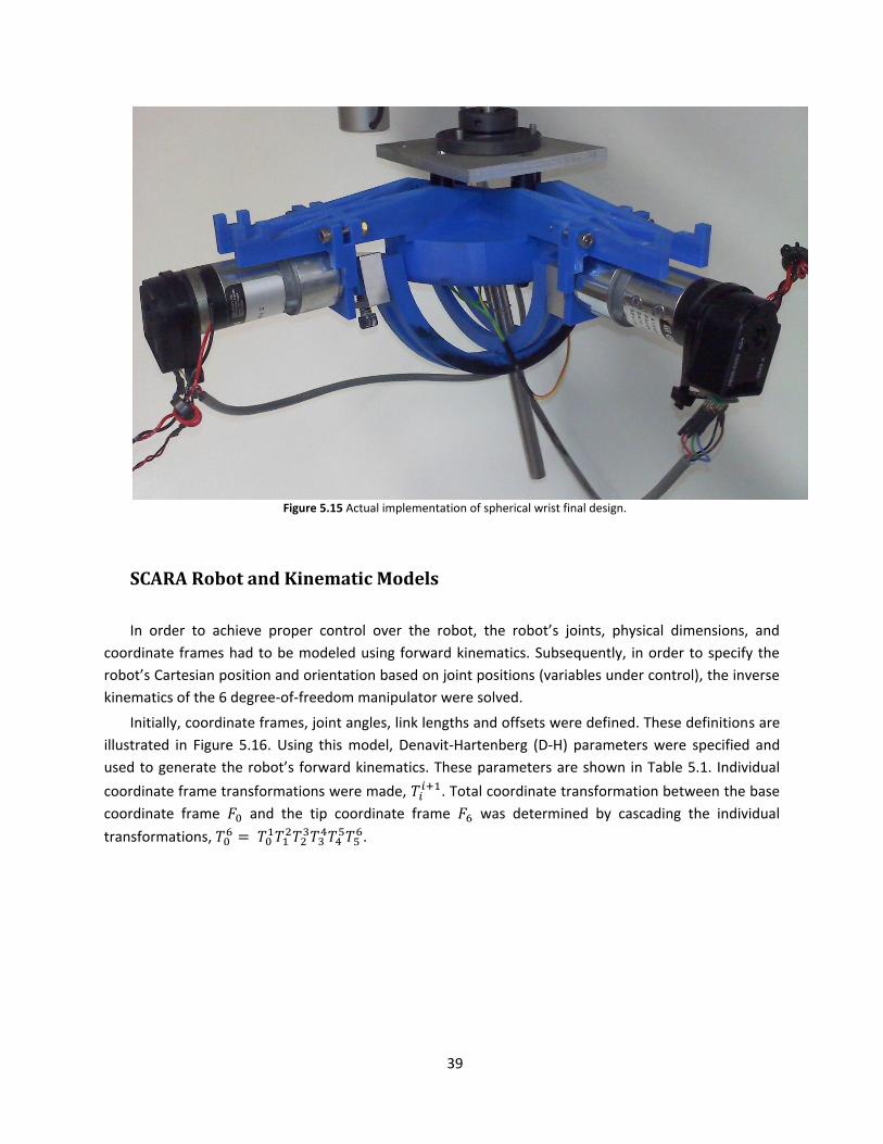
The assembled spherical wrist can be seen in Figure 5.15.
Figure 5.14 Final design of spherical wrist used to orient da Vinci surgical tool.
(1)
(2)
(3)
(4)
39
Figure 5.15 Actual implementation of spherical wrist final design.
SCARA Robot and Kinematic Models
In order to achieve proper control over the robot, the robot’s joints, physical dimensions, and
coordinate frames had to be modeled using forward kinematics. Subsequently, in order to specify the
robot’s Cartesian position and orientation based on joint positions (variables under control), the inverse
kinematics of the 6 degree-of-freedom manipulator were solved.
Initially, coordinate frames, joint angles, link lengths and offsets were defined. These definitions are
illustrated in Figure 5.16. Using this model, Denavit-Hartenberg (D-H) parameters were specified and
used to generate the robot’s forward kinematics. These parameters are shown in Table 5.1. Individual
coordinate frame transformations were made, . Total coordinate transformation between the base
coordinate frame and the tip coordinate frame was determined by cascading the individual
transformations, .

40
Figure 5.16: Coordinate frame definitions, assumed offsets, link lengths, and joint angle directions for the full 6 DOF robot.
Table 5.1: Corresponding D-H parameter list for full 6 DOF robot, all dimensions in millimeters.
Link RotZ TransZ TransX RotX Link 1 Ѳ1 621 350 0 Link 2 Ѳ2 0 250 0 Link 3 0 d3 - 241 0 0 Link 4 Ѳ4 0 0 π/2 Link 5 Ѳ5 + π/2 0 0 π/2 Link 6 Ѳ6 0 0 0
To confirm the kinematic model’s accuracy, a Matlab simulation (The MathWorks, Inc, Natick, MA,
USA) was created to visually plot the robot in 3D space. The simulation inputs were joint angles and its
output was the pose and orientation of the robot. Figure 5.17 details the simulation’s output.

41
Figure 5.17: Matlab simulation of Forward robot kinematics
Inverse kinematics were necessary to determine joint angles from a given Cartesian pose. Inverse
kinematics were determined through geometry. Knowing the geometry of the robot, joint angles theta
one and theta two were solved for in terms of a specified point (Px, Py, Pz). Note the translation of d3
directly maps to Pz so the calculation is intentionally overlooked in the process below.
Figure 5.18: Geometric layout of robot arm used inverse kinematics
Using the law of cosines, theta two was first solved for:
In a similar manner, Alpha and Beta were subsequently found:
x
y
Ѳ2
Ѳ1
α
β
(PX, PY, PZ)
a2
a1

42
The inverse orientation kinematics, specifying the tool’s orientation in 3D space, were found by
simple geometry. Here, theta five and theta six are the result from specifying a unit vector, the tool’s
approach vector.
One of the major design objectives outlined in the previous chapters was the establishment of a
remote center of motion about an arbitrarily fixed point in space. The concept of a tool being articulated
about a remote center is illustrated in Figure 5.20.
Figure 5.20: Articulation of a tool about a fixed remote center
In conjunction with the user’s desired input of the 3D Cartesian end-effecter position and fixed tool
length, the remote center will constrain all 6 degrees-of-freedom available on the research platform.
The end-effecter position and remote center together form a line. This line specifies the tool orientation
through a unique unit vector. Based on the tool’s orientation and internal and external lengths, the
robot’s wrist position is determined. Here, i denotes user input, r : remote center (Rc), Ti : the tool’s
internal length, To : the tool’s external length, u: the tool’s unit vector, and P : the robot’s wrist position.
The remote center calculations are depicted in Figure 5.20.
Tool Tip
(3 DOF)
Remote
Center
(fixed)
Tissue
Orientation
of Tool

43
Figure 5.20: Depiction of tool and arbitrarily placed remote center of motion. These calculations were run in real-time to solve
for the position and orientation of the robot’s wrist.

44
Implementation and Synthesis of Robot
Figure 5.21: Synthesis of the previously described subcomponents: Sony SCARA industrial robot, spherical wrist, tool
actuating module, torque sensing elements and force sensor module, and surgical tool.
The Sony SCARA robot, custom spherical wrist, surgical tool actuating module, force sensing elements
and module, as well as the surgical tool were all integrated and implemented. Figure 5.21 depicts the
synthesis of these major subcomponents.
Industrial Sony
SCARA robot
Custom spherical
wrist
Surgical tool
actuating module
da Vinci surgical tool
Software controlled
remote center of
motion

45
Robot Controller Hardware and Software
Hardware
In order to actuate the robot, command signals were generated by digital to analog converts (DACs)
on both the Poseidon embedded computer and Ruby-MM-4 analog output module (Diamond Systems,
Mountain View, CA, USA). These DACs were arranged in a bipolar configuration (±10 volts) and have 12
bits of resolution. A simple program was provided by Diamond Systems to interface with the DACs. Base
address, output range, and calibration options were set using onboard jumpers.
Because of the DC motors present on both the spherical wrist and industrial manipulator, the
command signals needed to be amplified. 6 LDH-S3 linear amplifiers (Western Servo Design, Carson City,
NV, USA) were utilized. These amplifiers were configured in a bipolar arrangement and could source up
to 2 amps continuous and 5 amps peak. Using analog potentiometers located on each amplifier board,
the amplifiers were zeroed and subsequently the gain was adjusted such that the ±10V DAC signal was
scaled to ±12 volts, the voltage required to run the DC motors. Additionally, a potentiometer was
provided to adjust the time constant of the amplifier, this was not used due the robot’s high inertia load.
Figure 5.22 illustrates the amplifiers used.
Figure 5.22: LDH-S3 Linear Amplifiers used amplifier control signals and control DC motors. Figure adapted from Western
Servo Design, Carson City, NV, USA
In order to interpret quadrature encoder signals coming from both the industrial manipulator
and the spherical wrist, a hierarchical interface was developed. 6 LS7366 32-bit quadrature counters
with serial interfaces (LSI/CSI, Melville, NY, USA) were used to capture and count the quadrature signals
coming from rotary encoders at each axis. An Atmega 644P microcontroller (ATMEL Corporation, San
Gain, Balance, and Time-constant
adjustment potentiometers
Command Signal Input
High Current Output

46
Jose, CA, USA) was used to interface with each positional encoder. This single microcontroller was
responsible for writing a read request (via 4 wire serial) and subsequently reading the 32-bit position
count from each of the 6 integrated circuits.
Using an FTDI USB to serial communication chip (Future Technology Devices International Ltd,
Glasgow, UK), reliable communication was established between the low level Atmega microcontroller
(TTL serial) and the embedded Linux computer (USB 2.0). The highest level controller, the embedded
Linux system, sends a read request to the Atmega microcontroller and subsequently reads 16 bytes of
data. Each joint position consists of 2 bytes and there are 4 additional bytes used to check the strings
beginning and end locations, as the data is sent sequentially joint by joint. The hierarchal structure of
this process is depicted in Figure 5.23.
Figure 5.23: Flow of positional data from robot to highest level control process. Steps include quadrature counter ICs,
microcontroller, and embedded Linux processor.

47
Software
The control process was written in C code in Linux User Space. The control process handles all
interaction with peripherals as well as the kinematics calculations. After the process is initialized, it reads
a packet of previously requested joint positions waiting in the serial buffer (read request is sent during
the previous execution of the control loop). Subsequently, joint torques are sampled from the sensor
module using the Poseidon’s ADCs. Representative Cartesian forces are determined and written to a
named shared memory allocation. A separate user space process, the Novint Falcon control code, reads
the shared memory allocation as soon as a synchronization semaphore has been allocated, indicating
the control process has finished writing the force structure to the memory location. In turn, the falcon
writes positional data from the user into a separate shared memory allocation before it is blocked by the
unavailability of the semaphore. Because of this, the control process is able to access the positional data
just prior to releasing the blocked falcon process.
The control process continues to compute the necessary joint angles to achieve the user’s specified
Cartesian pose by means of inverse kinematics. Once desired joint angles are determined, errors
between the previously read actual angles and the desired joint angles are determined. A PID control
loop attempts to converge these errors to zero and results in 6 independent control signals. Control
signals are written to the Ruby-MM-4 DAC module. Finally, the control process blocks until a binary
semaphore resource (handled by the Kernel) becomes available.
The Kernel allocates the mention binary semaphore every 1 ms. The control process is essentially
put to sleep until the resource becomes available. The kernel module takes advantage of the RTAI kernel
patch, utilizing a HAL (hardware abstraction layer) to achieve true real-time operation independent of
user space processes.

48
Figure 5.24: Flow of control process. The responsibilities of the control process as well as the peripherals and processes it
interacts with.
Kernel Module
Novint Falcon Process

49
User Haptic Interface
In order to provide haptic sensation to the user, a Novint Falcon haptic game controller (Novint,
Albuquerque, NM, USA) was used. This device not only allowed the position of the user’s hand to be
captured but also for forces to be transmitted to the user’s hand. In order to interface with the Falcon,
an open-source driver was utilized as there are no Linux drivers provided by the manufacturer.
Considerable time was spent compiling and implementing the driver. A separate process was used to
control the Falcon. This object oriented program read position data from the Falcon, computed forward
parallel robot kinematics to determine end effect position, and also applied specified Cartesian forces.
The design team’s control process interfaced with the Falcon’s process through the introduction of
named shared memory allocations. The control process wrote force data to a memory address for the
Falcon process to read, and likewise the Falcon process wrote positional data to a memory address for
the control process to read. Inter process communication was synchronized, again, through the use of
binary semaphores. This ensured memory was not accessed by multiple processes at the same time.
Control System Implementation
The final control system design was built and programmed. Figure 5.25 details the system
integration.
Figure 5.25: Developed a complete robot control system with real-time Linux PC, custom high-speed encoder interface,
amplifier modules, and haptic interface.
Single board, 1 Ghz
Poseidon embedded Linux
computer
6 Linear Amplifiers
Novint Falcon Haptic
Controller
Atmega 644P
microcontroller
And encoder counters Linux User Space and Linux
Kernel Space Programs

50
6. FINAL DESIGN VALIDATION
Several steps were taken by the design team to verify the devices functionality. In order to
validate the sensor module the team brought the subsystem to Children’s Hospital Boston, where Dr.
Hiep T. Nguyen allowed testing on an actual da Vinci Surgical System. The team fit the sensing module
on the robot and it successfully fit between the arm’s faceplate and the surgical tool. Figure 6.1 shows
the module fitting on the actual da Vinci surgical robot. It is important to note that this was the primary
objective of the sensing module; it must fit on the existing da Vinci device and hold the surgical tool. This
design objective was indeed accomplished.
Figure 2.1: Sensor module on da Vinci Surgical robot at Children’s Hospital Boston, confirming design objective
Figure 6.2: Further confirmation of device functionality, the arm was moved while the sensor module was attached.

51
Additionally, it was required that the force sensing module measure joint torques reliably with
repeatability. In order to confirm this objective sensor elements were individually calibrated. The design
team examined the calibrations’ linearity (the linear relationship between applied torque and sensor
signal after amplification using the designed amplifier module). Each sensor element showed extremely
high calibration linearity, with an R2 = 0.99. The calibration was performed by first fixing one end of the
sensing element to ground. Next, several precise weights were hung at a controlled distance. Applied
torque was calculated and sensor amplifier output was recorded at each applied torque. The
experimental set up for calibration procedures is shown in Figure 6.3. Curves and trend lines were
plotted using Microsoft Excel. Figure 6.4 illustrates the results of a sensor element calibration.
The minimal variance between sensor elements speaks to the repeatability of our methodical
approach. The high linearity confirms the theoretical calculations and design of our sensing element.
The design successfully met the objective of measuring tool interaction forces.
Figure 6.3: Test rig used to calibrate sensing elements. A magnetic clutch prevented one end of the sensor from rotating
while a load was systematically applied to the opposite end. Applied torque was calculated and amplified voltage output recorded.

52
Figure 6.4: The linearity calibration result for 1 of the 4 custom-made torque sensors that couple between the surgical
tools and the da Vinci robot.
Lastly, the design team confirmed the kinematic positioning of the robotic platform about a
remote center. Through multiple demonstrations, it was confirmed that the platform successfully and
reliably interpreted user input from the Novint Falcon, utilized this positional information to dictate
tool-tip position and maintained a remote center of motion at a simulated patient-machine interface.
Figure 6.5 illustrates the user inputting a desired tool-tip position and the robot achieving that tip
position while orienting the tool to maintain a remote center of motion.
y = 1.4799x - 0.0008R² = 0.9999
0
0.2
0.4
0.6
0.8
1
0 0.1 0.2 0.3 0.4 0.5 0.6 0.7
Vo
ltag
e S
ign
al (
Vo
lt)
Applied Torque (Nm)
Sensor Element Calibration

53
Figure 6.5: Design verification of robots ability to maintain remote center of motion while interpreting user input for end
effecter positioning.
Perhaps the greatest testament to the project’s success was the system wide integration of the
team’s developed subcomponents. The complex synergy arising from integrating multiple
subcomponents can often leave the final product in a non-functional state. Here, the haptic user
interface, robot control system (software and electronics), the custom spherical, tool actuator, and
sensor module all integrate into a solid research platform. Figure 6.6 details the final system wide
integration on the robot’s final design.

54
Figure 6.6: Final design implementation. A major objective of the project was successful system wide integration of the
research platform

55
7. DISCUSSION
Several accomplishments are worth elaborating on from the research team’s work. Concisely the
team successfully:
Created a simulated da Vinci arm using an industrial robot, custom spherical wrist, and a surgical
tool actuator module.
Developed a custom Linux-based control system and high speed encoder interface for the
robotic platform.
Developed a torque sensing module that interfaces between da Vinci surgical tools and the
robot’s arm (real da Vinci or our simulator) to measure tool-tissue interaction forces.
Implemented inverse kinematics control of the robot with virtual remote center of motion using
a haptic feedback input device.
A da Vinci arm’s functionality was properly reproduced. Although the da Vinci uses a mechanical
remote center of motion, the research team was able to employ a software remote center of
motion to achieve the same functionality. Although the design was only required to hold a remote
center that would minimize skin stretch at the point of entry into the patient, confirmation as to the
accuracy of the remote center and the tool tip position should be externally measured. The design
team suggests the use of fiducially tracking beads on both the remote center of motion and the end
effecter tip to quantify tool positioning errors. However, the team did attempt to minimize joint
space errors. Figure 7.1 depicts the desired and actual joint position of one of the robot’s 6 joints.
Control parameters were tuned until error was minimized.
Figure 3.1: Desired vs. actual trajectory of one of the robot's joints.
The robot’s spherical wrist was able to orient the surgical tool and integrate onto the existing
industrial manipulator. It was determined that, although there is room for both mechanical and
electric optimizations of this subcomponent, it met the functional requirements of the design and
easily provided two additional independent degrees-of-freedom.
Furthermore, the custom surgical tool actuator module was able to mount successfully to the
spherical wrist and was lightweight enough to be quickly reoriented. The actuator interfaced

56
properly with a da Vinci disposable faceplate, allowing surgical tools to be easily and reliably
mounted to the module. One element the design team did not successfully implement was the
positional control of the actuator module’s 4 DC motors. Although the control system was designed,
due to hardware lead times and project timing, the actuator module was left unpowered during
final demonstrations. This shortcoming did not inhibit the design team’s ability to confirm the
functionality of the rest of the system.
Perhaps one of the most influential contributions this project has brought to haptics research
and telesurgery is the force sensing module. This module seamlessly integrates between a da Vinci
arm and surgical tool, without modification to either device. Since custom force sensing elements
were developed to externally capture joint torques, the sensing module does not inhibit the da
Vinci’s functionality. The module’s low profile and relatively slim packaging are testament to its
requirements of not interfering with the surgical workspace. Of all subcomponents, the design team
believes this module may have the greatest potential to influence future research.
The sensor elements are highly reliable. Torques within the specified operational range were
measured precisely. Perhaps the most important thing to note is that with simple manufacturing
and assembly, these well-designed sensors show promising performance, easily capturing joint
torques. However, with slight improvements in manufacturing and the quality of strain gage
elements, these sensors could see even further success and be applied in a multitude of applications
requiring direct torque measurement.
The Linux-based control system developed for this project shows that real-time control of a
robotic platform is complex but very possible to do with readily available components. Although the
organization and integration of the control system’s components was unique, the components
themselves are inexpensively available. The design team found it difficult to configure the Linux
Kernel with the RTAI patch, however this may be attributed to the team’s inexperience with the
Linux operating system prior to this project. The development of this real-time system will enable
future telesurgery research at WPI.
The haptic interface enables forces to be easily applied to the operator’s hand. Although the
design team’s chosen interface, the Novint Falcon, is only capable of applying forces in three
dimensions, research indicates that for some surgical maneuvers this may be sufficient (Verner and
Okamura). Also, the simplification of the haptic interface reduces cost considerably, with the cost of
a Falcon device currently under $200. The interface is at least a starting point for the haptics
research platform and can be easily exchanged with another commercially available system or
custom device.

57
8. FUTURE WORK
There are several elements the team envisions in terms of future work. The first is user evaluation.
Using the robotic da Vinci simulator, evaluations should be performed assessing an individual’s ability to
interpret tool-tissue interaction forces. This will help determine which tool-interaction forces are
important and worth feeding back to the user via the haptic device. Such questions as: What sensitivity
in tool interaction forces is necessary to distinguish between common tissue types? What mapping of
tool-interaction forces to Cartesian haptic forces is most effective for the user to interpret the internal
environment of a simulated patient? And, how can the user or an algorithm effectively control and
optimize the amount and timing of haptic feedback to increase procedural efficient? are important for
future research.
Furthermore, the research team believes it would be worthwhile to investigate how latency
between user input/feedback and robot motion affect a procedure. What is a tolerable amount of delay
in real-time surgery and how can unacceptable delays be compensated for in remote telesurgery. This
field is in its infancy and such work would provide necessary information to researchers.
The team envisions a more robust and stable robot. Mechanical stabilization of the wrist, motor
module, and actuator module should be considered. Given the time constrains of the project, the team
had virtually no time to optimize and further redesign mechanical components.
Lastly, a clinically viable solution would benefit surgeons and other medical practitioners. If this
single da Vinci arm could be used in a clinical scenario, it may add flexibility to robot-assisted
procedures. Perhaps more feasibly, the robotic platform could assist in the training of practitioners.
Logging time on a multimillion dollar system that is rarely available can increase the learning curve of
robot-assisted surgery. However, if an independent system can be utilized to train practitioners, the
system could potentially decrease the time it takes a surgeon to become proficient at robot-assisted
surgery.

58
REFERENCES
1. Berkelman, Peter and Ji Ma. "A Compact Modular Teleoperated Robotic System for
Laparoscopic Surgery." The International Journal of Robotics Research 28 (2009): 1198–
1215.
2. Elhage, Oussama, et al. "Robotic Urology in the United Kingdom: Experience and Overview."
J Robotic Surg 1 (2008): 235–242.
3. Feller, R L, et al. "The Effect of Force Feedback on Remote Palpation." IEEE International
Conference on Robotics and Automation. New Orleans, 2004.
4. Haidegger, Tamas, et al. "Force Sensing and Force Control for Surgical Robots." Proceedings
of the 7th IFAC Symposium on Modelling and Control in Biomedical Systems. Aalborg,
Denmark: IFAC, 2009.
5. Intuitive Surgical. Intuitive Surgical - Products. 2010. 25 4 2010
<http://www.intuitivesurgical.com/products/index.aspx>.
6. Ishii, Chiharu, et al. "Robotic Forceps Manipulator With a Novel Bending Mechanism."
IEEE/ASME TRANSACTIONS ON MECHATRONICS (2010).
7. Lenihan, John P, Carol Kovanda and Usha Seshadri-Kreaden. "What is the Learning Curve for
Robotic Assisted Gynecologic Surgery?" Journal of Minimally Invasive Gynecology 15 (2008):
589-594.
8. Lum, Mitchell J H, et al. "The RAVEN: Design and Validation of a Telesurgical System." The
International Journal of Robotics Research 28 (2009): 1183–1197.
9. Mahvash, M and A Okamura. "Friction Compensation for Enhancing Transparency of a
Teleoperator with Compliant Transmission." IEEE Transactions on Robotics 23 (2007): 1240-
1246.
10. Mottrie, Alexandre M. "The Introduction of Robot-Assisted Surgery in Urologic Practice:
Why Is It So Difficult?" European Urology 57 (2010): 747-749.
11. Okamura, A M. "Methods for Haptic Feedback in Teleoperated Robot-Assisted Surgery."
Industrial Robot: An International Journal 31 (2004): 499–508.
12. Scales, Charles D, et al. "Local Cost Structures and the Economics of Robot Assisted Radical
Prostatectomy." The Journal of Urology 174 (2005): 2323–2329.
13. Spong, Mark W, Seth Hutchinson and Vidyasagar M. Robot Dynamics and Control. Wiley,
1989.
14. Sun, L W, et al. "Advanced da Vinci surgical system simulator for surgeon training and
operation planning." Int J Med Robotics Comput Assist Surg 3 (2007): 245–251.
15. Trejos, A L, et al. "Robot-assisted Tactile Sensing for Minimally Invasive Tumor Localization."
The International Journal of Robotics Research 28 (2009): 1118-1133.

59
16. Verner, Lawton N and Allison M Okamura. "Force & Torque Feedback vs Force Only
Feedback." Third Joint Eurohaptics Conference and Symposium on Haptic Interfaces for
Virtual Environment and Teleoperator Systems. Salt Lake City: IEEE, 2009.