force and measurement and wind tuunel balance
TRANSCRIPT
Wind-tunnel Force and Measurement and Wind
Tuunel Balance
By
Sangram Samal

Force Measurement
The aerodynamic forces and moments acting on models tested in wind tunnels can be determined indirectly by measuring the pressures at many points of the model surface. Using wind-tunnel balances directly the forces and moments can be measure for a model.
A wind tunnel balance is device to measure the actual forces and moments acting on a model placed in a test section. Wind tunnel balance should have following characteristics for better measurement.
1. Balance should be capable of measuring the various component ( 1 to 6 component)
2. The forces and moment can be measure at deferent angle of attack using the balance
3. The support system of balance should be highly rigidity
4. Use of bearing should be avoided as they cause large error

Based on the construction details, the wind tunnel balances are broadly classified as
1. Wire-type Balance
2. Strut-type Balance
1. Platform-type Balance
2. Yoke-type Balance
3. Pyramid-type balance
3. Strain gauge-type Balance
1. Internal Balance
2. Semi-internal Balance
3. External Balance
Wire-type Balance
In wire type balance the model is supported by the wire only. The forces are transmitted to the measuring device by the wire. This type of balance is simplest to build. Following are disadvantages due to use of bearing and crank systems and friction of the wire.

• Large tare drag because of the exposed wire. Difficult to measure this drag accurately
• Error is occurred due to bearing and the linkage
• Wire is tendency to break
• Wire will take only tension (no compression)
The usual arrangement of wire type of balance as follows:
• Model are tested in inverted position
• The wire will take only tension, so it is essential to arrange the wires such that, for all type forces (lift and drag), the wire should be in tension
• Conventional three-points attachment is provided on the model pulleys, ball bearings and leaver arm to transfer the loads to the measuring device.
• The principle of measuring forces (lift and drag), used when the model is flexibly supported, is illustrated in Figure

• The vertical force Y is directly taken up by wires (1) and (2), pre-tensioned by counterweights GI and G2.
• The change in tension in wire (3), which is measured by balance element BEQ, is equal to the drag Q of the model.

Strut-type Balance
• Wire type balances are used very less in large tunnel. The strut types are proved to be suitable device to measure the forces in wind tunnel. Based on the construction, strut-type balances are classified as:
1. Platform-type Balance
2. Yoke-type Balance
3. Pyramid-type Balance
• Strut are used to support the model and transmit the forces to measuring device. Conventionally the model is moistened by three point mounting (two on wing and one on rear fuselage of aircraft model). The advantages of strut-type balance are:
1. The strut is very rigid and their deflection (error) is very small
2. The drag(tare and interference) of the strut is very small
3. By selecting the linkage system the interaction load can be reduce to a small value
4. Weight of support system can be kept very small

Platform-type Balance
• There is only one mounting point on fuselage, by which the model is mounted
• The model is supported on the platform by a single streamlined strut
• The interference is minimum due to single mounting system from model
• The model is supported with the platform with this single supported
• The platform is supported three point as shown in fig
• The load is calculated as
Yoke-type balance
• The model is supported on balance single streamlined strut like platform type balance
• The model is mounted on a yoke as shown in fig
Pyramid-type Balance
• In pyramid-type balance. The model mounting is about one point connecting the model to platform by four arms
• pyramid-type balance, compared to the platform or yoke type, has specific advantage.
• In this the forces and moments acting on the model are measured with respect to single point (attached point)
• The error in this balance is less compare to other two type of balance
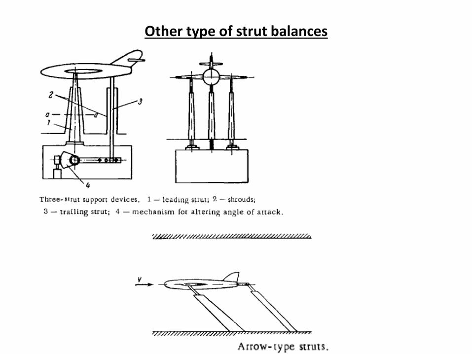
Other type of strut balances


The effect of the model supports and struts
• The components used to support the model obstruct the flow, and cause a general change in velocity and pressure distributions around them; this, in turn, affects the magnitude of the aerodyhamic forces acting on the model. The supports also cause interference with nearby components of the model. Furthermore, the aerodynamic forces acting on the supports are partially transmitted to the wind-tunnel balance used for measuring the aerodynamic forces acting

Strain-Gauge Balance
When strain gauge is used as load sensing element in wind tunnel balance is called Strain-Gauge Balance.Based on the strain gauge fixing on the model, the strain gauge balances are classified as
1. Internal Balance
2. Semi-internal balancef
3. External Balance
Internal Balance
• In internal Balance, all the measuring elements are located inside the model.
Semi-internal balance
• In semi-internal balance the measuring elements are located partially inside and partially outside the model.
External balance
• In an external balance all measuring elements are located outside the balance
Three-component and six component balance
The main characteristic of wind-tunnel balances is the number of measured components. Depending on the problem considered, this number can vary from 1 to 6.
Three-component wind-tunnel balances
• When solving a two-dimensional problem, for instance, for a symmetrical model of an airplane at zero slip angle, three-component balances are used, which measure the lift, the drag, and the pitching moment.
• In this case the balance must have a mechanism permitting only the angle of attack to be changed.
Six-component wind-tunnel balances
• Full-scale tunnels usually have six-component wind-tunnel balances on which the aircraft is installed
• Using six-component balances, the three components of forces, three components of moments are measured

Strain Gauge Operation Theory
• When the bakelite body of the gauge is connected to the surface of the structure, it will stretch or contract with the outer fibers of the structure to which it is attached. The grid wire embedded in the bakelite will stretch or contract with the bakeelite body. As the grid wire are stretched the cross sectional area decreases, causing an increase in electrical resistance. Similarly as the grid wire are compressed their cross-sectional area increases, causing a deacrease in electrical resistance.
• From experience it is found that the change in resistance of the types of strain gauges normally used in wind tunnel balance is directly proportional to the stress in the outer fiber of the structure to which it is attached.
• Fundamental equation for strain gauges are:
GF = (∆R/R) / (∆L/L)
where
GF = Gauge Factor,
R = Resistance of strain gauge
L = length of strain gauge
∆R and ∆L are the change in resistance and length of strain gauge

And e = σ/E = (∆L/L)
Where
E = Yong’s modulus
σ = is stress
e = strain
From above two equation
σ = (∆R E) / (R GF)
Load can be find out after knowing the σ

Calibration of measuring instruments
• Proper calibration of balance is required for interpretation of wind tunnel test result in terms of the desired forces and moment
• The main purpose of calibrating measuring instruments is to establish the dependence between the measured value t and the indication u of the measuring instrument. The dependence is in most cases linear and for its determination it is sufficient to find the calibration constant of the instrument, i. e., k=t/u.
• Another purpose of calibration is to determine the accuracy characteristics of the instrument
• In general the calibration comprise the mounting of the balance on a calibration rig outside the tunnel, loading the balance with the known forces and moments which cover the range expected during the test.
• Record all the known applied (t) load and displayed (u) load by the instrument. From this ‘linearity’ or constant can be find out
• Difference between the gage (instrument) reading with the no load taken before and after a loading is termed as ‘gage drift’

• The calibration constant is determined on the basis of p measurements of ui corresponding to standard values ti (i varies from 1 to p). If the values of ui and ti are plotted, a straight line can be drawn through the experimental points as shown ion fig, whose equation is

• There are basically two types of error (systematic error and random error) found in wind tunnel balance
• The main sources of errors of the wind-tunnel balances are:
1) Inaccurate assembly of the system for separating the forces into components ;
2) Displacements and deformations of the links due to variations in load, temperature, and pressure;
3) Inexact transmission ratios of levers;
4) Deformation of the model supports.
• These are systematic errors which can be found and eliminated when calibrating the balance. In wind-tunnel balances the most characteristic systematic errors are those expressed by the interaction of the components.
• Random errors are caused mainly by friction in the hinges of the links

Wind tunnel Boundary correction
• Inside the test section there is longitudinal static pressure gradient due to B/L growth and present of the model.
• The variation of static pressure along the test section produces a drag force known as horizontal bouncy. It is present in closed test section but neglected in open jet test section
• Due to the test section wall following blockings are created in test section
Solid Blocking
• Flow pattern is changed around the model due to test section wall. This will cause to increase in dynamic pressure , forces and moments. For open test section this can be neglected
Wake Blocking
• Flow pattern is changed about the wake is known as wake blocking. This effect increase with wake size. For a closed test section wake blocking increases the drag of the model. For open test section this is neglected
