for your cobra 29 wx nw bt fcc regulations cb radio · ch19 ch9 nor o m ax min max wx 29wxnw rx/tx...
TRANSCRIPT

SIG 1 3 5 7 9 +30dB
2 3 CAL
RF
SWR
RF
S/RF
SWR
CAL
NB/ANLANL
OFF
CB
PA
CH19
CH9
NOR
MIN MAX MIN MAXOFF
VOL SQ L
CB
WX
29 WX NW
RX/TXWX
WEATHERRF GAINDYNA DIM
7
1 6
2 5
3 4
ANT
T BACK SWR CAL
The Citizens Band lies between the shortwavebroadcast and 10-meter Amateur radio bands,and was established by law in 1949. The Class Dtwo-way communications service was opened in1959. (CB also includes a Class A citizens band and Class C remote control frequencies.)
FCC RegulationsFCC regulations permit only “transmissions” (one party to another) rather than “broadcasts” (to a wide audience). Thus, advertising is notallowed on CB Channels because that is “broad-casting.”
FCC Warnings All transmitter adjustments other than those supplied by the manufacturer as front panel operating controls, must be made by, or under the supervision of, the holder of an FCC-issuedGeneral Radio-Telephone Operator’s License.
Replacement or substitution of transistors, regulardiodes or other parts of a unique nature, withparts other than those recommended by Cobra,may cause violation of the technical regulations of Part 95 of the FCC Rules, or violation of TypeAcceptance requirements of Part 2 of the Rules.
You should read and understand Part 95 (includedwith this unit) of the FCC Rules and Regulations,before operating your Cobra radio, even thoughthe FCC no longer requires you to obtain an oper-ator’s license.
What’s Included with Your 29 WX NW BT1. CB transceiver 6. Operating Manual2. Microphone 7. DC power cord3. External Bluetooth® Mic 8. FCC rules4. Transceiver bracket (not shown)5. Microphone bracket
29 WX NW BT
©2008 Cobra Electronics CorporationPrinted in ChinaPart No. 480-532-P-001 Version A
CB Radio
Nothing Comes Close to a Cobra®
Operating Instructions for your Cobra 29 WX NW BT
The CB Story
For technical assistance, please call our Automated Help Desk which can assist
you by answering the most frequently asked questions about Cobra products.
(773) 889-3087 24 hours a day, 7 days a week.
A Consumer Service Representative can be reached through this same number 8:00 am - 5:30 pm, Monday through Friday, Central Time.
Technical assistance is also available on-line in the Frequently Asked Questions (FAQ) section atwww.cobraelec.com or by e-mail to [email protected]
If you think you need service call 1.773.889.3087
“If your product should require factory service please call Cobra first before sending your unit in. This will ensure the fastest turn-around time on your repair.”
You may be asked to send your unit to the Cobra factory. It will be necessary to furnish the follow-ing in order to have the product serviced and returned.
1. For Warranty Repair include some form of proof-of-purchase, such as a mechanical reproductionor carbon or a sales receipt. If you send the original receipt it cannot be returned.
2. Send the entire product.
3. Enclose a description of what is happening with the unit. Include a typed or clearly print nameand address of where the unit is to be returned.
4. Pack unit securely to prevent damage in transit. If possible, use the original packing material.
5. Ship prepaid and insured by way of a traceable carrier such as United Parcel Service (UPS) or FirstClass Mail: to avoid loss in transit to: Cobra Factory Service, Cobra Electronics Corporation, 6500W. Cortland St., Chicago, IL 60707.
6. If the unit is in warranty, upon receipt of your unit it will either be repaired or exchangeddepending on the model. Please allow approximately 3 to 4 weeks before contacting us for status. If the unit is out of warranty a letter will automatically be sent informing you of the repair charge or replacement charge. If you have any questions, please call 1.773.889.3087 forassistance.
Trademark InfoCobra®, Dynamike®, Nothing Comes Close to a Cobra® and the snake design are registered trademarks of Cobra Electronics Corporation, USA.
Cobra Electronics Corporation™ is a trademark of Cobra Electronics Corporation, USA.
The Bluetooth® word mark and logo are registered trademarks owned by Bluetooth SIG, Inc.
If You Think You Need Service
3
2
5
6
1
cb tranceiver
4
29WXNWBT_MANL.qx:29WXNWBT_MANL.qx 1/7/09 4:26 PM Page 40
Downloaded from www.cbradio.nl
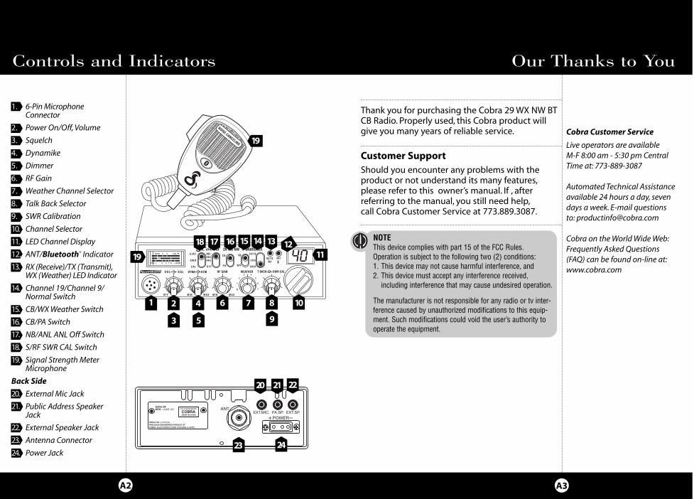
Thank you for purchasing the Cobra 29 WX NW BTCB Radio. Properly used, this Cobra product willgive you many years of reliable service.
Customer SupportShould you encounter any problems with theproduct or not understand its many features,please refer to this owner’s manual. If , after referring to the manual, you still need help,call Cobra Customer Service at 773.889.3087.
Controls and Indicators
Cobra Customer Service
Live operators are available M-F 8:00 am - 5:30 pm CentralTime at: 773-889-3087
Automated Technical Assistanceavailable 24 hours a day, sevendays a week. E-mail questionsto: [email protected]
Cobra on the World Wide Web:Frequently Asked Questions(FAQ) can be found on-line at:www.cobra.com
Our Thanks to You
A3A2
1. 6-Pin MicrophoneConnector
2. Power On/Off, Volume
3. Squelch
4. Dynamike
5. Dimmer
6. RF Gain
7. Weather Channel Selector
8. Talk Back Selector
9. SWR Calibration
10. Channel Selector
11. LED Channel Display
12. ANT/Bluetooth® Indicator
13. RX (Receive)/TX (Transmit),WX (Weather) LED Indicator
14. Channel 19/Channel 9/Normal Switch
15. CB/WX Weather Switch
16. CB/PA Switch
17. NB/ANL ANL Off Switch
18. S/RF SWR CAL Switch
19. Signal Strength MeterMicrophone
Back Side
20. External Mic Jack
21. Public Address Speaker Jack
22. External Speaker Jack
23. Antenna Connector
24. Power Jack
1 2 4
53
SIG 1 3 5 7 9 +30dB
2 3 CAL
RF
SWR
RF
S /RF
S WR
C A L
N B/AN LAN L
O F F
CB
PA
CH19
CH9
NOR
M IN M A X MI N MAXOFF
VOL SQL
CB
W X
29 WX NW
RX/TXWX
WEATHERRF GAINDYNA DIM
7
1 6
2 5
3 4
ANT
T BACK SWR CAL
6 7 8
23 24
19 111213
20 21
1415161718
19
Intro Operation CustomerAssistance
Warranty
Notice
Main Icons
Secondary Icons
Caution Warning
Installation CustomerAssistance
NOTEThis device complies with part 15 of the FCC Rules.Operation is subject to the following two (2) conditions: 1. This device may not cause harmful interference, and 2. This device must accept any interference received, including interference that may cause undesired operation.
The manufacturer is not responsible for any radio or tv inter-ference caused by unauthorized modifications to this equip-ment. Such modifications could void the user’s authority tooperate the equipment.
9
22
10
29WXNWBT_MANL.qx:29WXNWBT_MANL.qx 1/7/09 4:26 PM Page 43

How to Use YourCobra 29 WX NW BT
Contents
Features..................................................................................................1The CB Story.........................................................................................A1FCC RegulationsFCCWarningsIncluded Accessories
Controls & Indicators .......................................................................A2Our Thanks to You .............................................................................A3SoundTracker™Customer Support
InstallationLocation .............................................................................................2Mounting and Connection .........................................................2
AntennasCB Antenna.......................................................................................6Marine Installation .........................................................................6
Ignition Noise Interference ..........................................................7Operating Your 29WX NW BTTurning On Your CB........................................................................8Setting Channel Selector .............................................................9Calibrate For SWR (StandingWave Ratio)..............................10To Receive..........................................................................................12Selecting a Channel .......................................................................13S-Meter ...............................................................................................13NB-ANL/ANL/Off (Noise Blanker/Automatic.........................16Noise Limiter Switch)
CB/WX Switch...................................................................................17RF Gain Control................................................................................17Dimmer Switch ................................................................................18Setting Squelch ...............................................................................18To Transmit........................................................................................20Setting Dynamike® .........................................................................20Transmit..............................................................................................21RF Meter .............................................................................................22External Speaker .............................................................................23PA (Public Address) ........................................................................24Weather Channels ..........................................................................26Home And Office Set-Up .............................................................28Temporary Mobile Set-Up ...........................................................29
HowYour CB Can Serve You..........................................................30A Few Rules You Should Know..................................................30Channel 9 Emergency Messages..............................................30Weather Channel Messages .......................................................31CB 10 Codes......................................................................................32
Frequency Ranges.............................................................................3429WX NW BT Specifications ........................................................35Warranty Information .....................................................................36Optional Accessories .................................................................37-38Order Form ...........................................................................................39If You Need Service/Trademark Info ......................Back Cover
Features of This Product
• 7Weather Channels
• EmergencyWeather Alert
• Bluetooth® Connectivity
• 40 CB Radio Channels
• SoundTracker® System
• Heavy-Duty DynamicMicrophone
• Full 4Watts AMRF Power Output
• SWR Calibration Meter
• Instant Channel 19 and 9
• Front Panel 6-Pin MicrophoneConnector
• Switchable Automatic NoiseLimiter & Noise Blanker
• Adjustable Dynamike Boost
• Tactile Controls
• 9 Ft Mic Cord
• Illuminated Front Panel
• Dimmer Control
• RF Gain
1
CAUTION: TO REDUCE THE RISK OF ELECTRICSHOCK DO NOT REMOVE COVER (OR BACK)
NO USER SERVICEABLE PARTS INSIDEREFER SERVICING TO QUALIFIED SERVICE
PERSONNEL
CAUTIONRISK OF ELECTRIC SHOCK
DO NOT OPEN
29WXNWBT_MANL.qx:29WXNWBT_MANL.qx 1/7/09 4:26 PM Page 1
InstallationInstallation
Location
32
Mounting andConnection
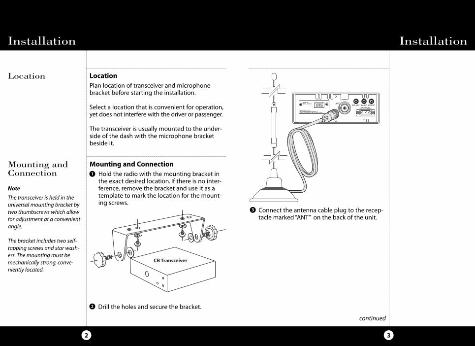
Mounting and ConnectionHold the radio with the mounting bracket inthe exact desired location. If there is no inter-ference, remove the bracket and use it as atemplate to mark the location for the mount-ing screws.
LocationPlan location of transceiver and microphonebracket before starting the installation.
Select a location that is convenient for operation,yet does not interfere with the driver or passenger.
The transceiver is usually mounted to the under-side of the dash with the microphone bracketbeside it.
Note
The transceiver is held in theuniversal mounting bracket bytwo thumbscrews which allowfor adjustment at a convenientangle.
The bracket includes two self-tapping screws and star wash-ers. The mounting must bemechanically strong, conve-niently located.
continued
Drill the holes and secure the bracket.2
1
Connect the antenna cable plug to the recep-tacle marked “ANT” on the back of the unit.
3
29WXNWBT_MANL.qx:29WXNWBT_MANL.qx 1/7/09 4:26 PM Page 2
InstallationInstallation
54
Note
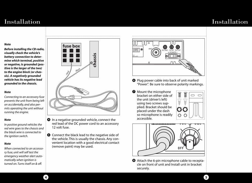
Before installing the CB radio,visually check the vehicle’sbattery connection to deter-mine which terminal, positiveor negative, is grounded (pos-itive is the larger of the two)to the engine block (or chas-sis). A negatively groundedvehicle has its negative leadgrounded to the chassis.
Note
Connecting to an accessory fuseprevents the unit from being lefton accidentally, and also per-mits operating the unit withoutrunning the engine.
Note
In positive ground vehicles thered wire goes to the chassis andthe black wire is connected tothe ignition switch.
Note
When connected to an accesso-ry fuse, unit will self test theemergency weather alert auto-matically when ignition isturned on.Turns itself on & off.
In a negative grounded vehicle, connect thered lead of the DC power cord to an accessory12 volt fuse.
Connect the black lead to the negative side ofthe vehicle.This is usually the chassis. Any con-venient location with a good electrical contact(remove paint) may be used.
4
5
Plug power cable into back of unit marked“Power”. Be sure to observe polarity markings.
Mount the microphonebracket on either side ofthe unit (driver’s left)using two screws sup-plied. Bracket should beplaced under the dashso microphone is readilyaccessible.
6
7
Attach the 6-pin microphone cable to recepta-cle on front of unit and Install unit in bracketsecurely.
8
V OL S QL R
OFF
29WXNWBT_MANL.qx:29WXNWBT_MANL.qx 1/7/09 4:26 PM Page 4
Ignition Noise InterferenceAntennas
Use of a mobile receiver at low signal levels isnormally limited by the presence of electricalnoise.The primary source of noise in automobilesis from the alternator and ignition system.Typically, when signal level is adequate, the back-ground noise does not present a serious problem.Also, when extremely low level signals are beingreceived, the transceiver may be operated withthe vehicle’s engine turned off. The unit requiresvery little current and therefore will not signifi-cantly discharge the vehicle’s battery.
Even though the Cobra 29WX NW BT has anautomatic noise limiter, in some installations igni-tion interference may be high enough to makegood communications impossible.Many possibili-ties exist and variations between vehicles requiredifferent solutions. Consult your COBRA dealer ora 2-way radio technician for help in locating thesource of a severe noise.
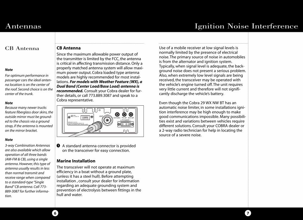
CB AntennaSince the maximum allowable power output ofthe transmitter is limited by the FCC, the antennais critical in affecting transmission distance.Only aproperly matched antenna system will allow maxi-mum power output. Cobra loaded type antennamodels are highly recommended for most instal-lations. Formodels withWeather Feature (WX), aDual Band (Center Load/Base Load) antenna isrecommended. Consult your Cobra dealer for fur-ther details, or call 773.889.3087 and speak to aCobra representative.
Marine InstallationThe transceiver will not operate at maximumefficiency in a boat without a ground plate,(unless it has a steel hull). Before attemptinginstallation , consult your dealer for informationregarding an adequate grounding system andprevention of electrolysis between fittings in thehull and water.
CB Antenna
7
Note
For optimum performance inpassenger cars the ideal anten-na location is on the center ofthe roof. Second choice is on thecenter of the trunk.
NoteBecause many newer trucksfeature fiberglass door skins, theoutside mirror must be ground-ed to the chassis via a groundstrap, if the antenna is mountedon the mirror bracket.
Note
3-way Combination Antennasare also available which allowoperation of all three bands(AM-FM & CB), using a singleantenna.However, this type ofantenna usually results in lessthan normal transmit andreceive range when comparedto a standard-type “SingleBand” CB antenna. Call 773-889-3087 for further informa-tion.
6
1 A standard antenna connector is providedon the transceiver for easy connection.
29WXNWBT_MANL.qx:29WXNWBT_MANL.qx 1/7/09 4:26 PM Page 6

The CB/PA button should be in theCB position.
Operation
9
Operation
Turning On Setting ChannelSelector
8
Turning OnMake sure the power cord, antenna and micro-phone are connected to their proper connectorsbefore starting.
Setting Channel Selector
2
SIG 1 3 5 7 9 +30dB
2 3 CAL
RF
SWR
RF
S/RF
SWR
CAL
NB/ANLANL
OFF
CB
PA
MIN MAX MIN MAXOFF
VOL SQL
29 WX N
RF GAINDYNA DIM
1
Rotate the On/Off Volume knob clockwise toa normal listening level.
Select one of forty channels and adjustvolume.The selected channel is indicated bythe LED readout directly above the channelselector knob
1
NB/ANLANL
OFF
CB
PA
CH19
CH9
NOR
M AX MIN MAXO
CB
WX
29 WX NW
RX/TXWX
WEATHERRF GAINM
7
1 6
2 5
3 4
ANT
T BACK SWR CAL
SIG 1 3 5 7 9 +30dB
2 3 CAL
RF
SWR
RF
S/RF
S WR
CAL
NB/ANLANL
OFF
CB
PA
MIN MAX MIN MAXO F F
VO L SQL
29 WX N
RF GAINDYNA DIM
29WXNWBT_MANL.qx:29WXNWBT_MANL.qx 1/7/09 4:26 PM Page 8

NB/ANLANL
OFF
CB
PA
CH19
CH9
NOR
AX MIN MAXO
CB
WX
29 WX NW
RX/TXWX
WEATHERRF GAINM
7
1 6
2 5
3 4
ANT
T BACK SWR CAL
While holdingmicbutton adjust theSWR CAL knob so themeter needle swingsto the CAL � mark onthe meter (located on the right).
OperationOperation
Calibrate ForSWR (StandingWave Ratio)
1110
continued
Note
Calibration must be made in anopen area (never in a garage).Vehicle doors must be closed.Noone should be standing near theantenna. (See your antennadirections for more completeinformation).
NoteThe reading will be slightly high-er on Channels 1 and 40 com-pared to Channel 20.
Push and holdmic button.
Switch to the CAL position.2
1
3
Calibrate for SWR (StandingWave Ratio)SWR calibration is done to properly adjust thelength of the antenna and to monitor the qualityof the coaxial cable and all RF connections.This calibration is critical in order to achieve opti-mum performance.
SIG 1 3 5 7 9 +30dB
2 3 CAL
RF
SWR
RF
S/RF
SWR
CAL
NB/ANLANL
OFF
CB
PA
MIN MAX MIN MAXOFF
VOL SQL
W
29 WX NW
RF GAINDYNA DIM
1
PUSH &HOLD
Select channel 20.
4
NB/ANLANL
OFF
CB
PA
CH19
CH9
NOR
MAX MIN MAXO
CB
WX
29 WX NW
RX/TXWX
WEATHERRF GAINM
7
1 6
2 5
3 4
ANT
T BACK SWR CAL
SIG 1 3 5 7 9 +30dB
2 3 CALSWR
RF
29WXNWBT_MANL.qx:29WXNWBT_MANL.qx 1/7/09 4:26 PM Page 10
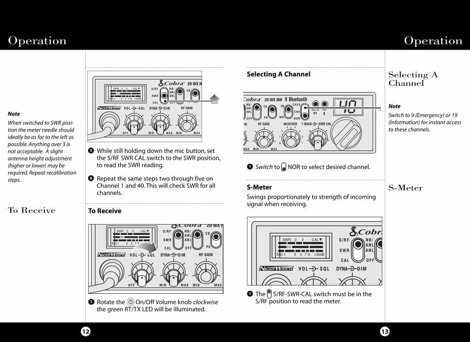
Rotate the On/Off Volume knob clockwisethe green RT/TX LED will be illuminated.
Repeat the same steps two through five onChannel 1 and 40.This will check SWR for allchannels.
The S/RF-SWR-CAL switch must be in theS/RF position to read the meter.
6
While still holding down the mic button, setthe S/RF SWR CAL switch to the SWR position,to read the SWR reading.
5
Operation
13
Operation
12
1
Note
When switched to SWR posi-tion the meter needle shouldideally be as far to the left aspossible. Anything over 3 isnot acceptable. A slightantenna height adjustment(higher or lower) may berequired. Repeat recalibrationsteps.
S-MeterS-MeterSwings proportionately to strength of incomingsignal when receiving.
Switch to NOR to select desired channel.1
Selecting AChannel
Selecting A Channel
Note
Switch to 9 (Emergency) or 19(Information) for instant accessto these channels.
NB/ANLANL
OFF
CB
PA
CH19
CH9
NOR
M MAX MIN MAXO
CB
WX
29 WX NW
RX/TXWX
WEATHERRF GAINM
7
1 6
2 5
3 4
ANT
T BACK SWR CAL
To Receive
1
To Receive
SIG 1 3 5 7 9 +30dB
2 3 CAL
RF
SWR
RF
S/RF
SWR
CAL
NB/ANLANL
OFF
CB
PA
MIN MAX MIN MAXOFF
VOL SQL
29 WX N
RF GAINDYNA DIM
1
SIG 1 3 5 7 9 +30dB
2 3 CAL
RF
SWR
RF
S/R F
S W R
CAL
NB/ANLA NL
O F F
C B
PA
MIN MAX MIN MAXOFF
VOL SQL
29 WX N
RF GAINDYNA DIM SIG 1 3 5 7 9 +30dB
2 3 CAL
RF
SWR
RF
S/RF
SWR
CAL
NB/ANLANL
OFF
C
V OL S QL DYNA DIM
29WXNWBT_MANL.qx:29WXNWBT_MANL.qx 1/7/09 4:26 PM Page 12
OperationOperation
Bluetooth®
1514
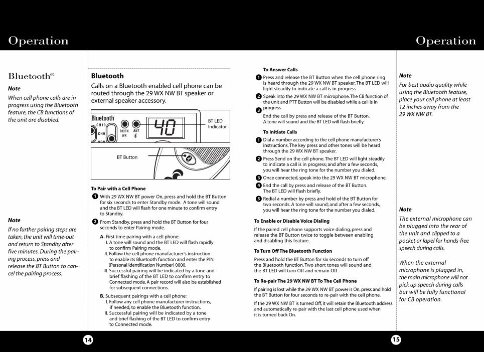
BluetoothCalls on a Bluetooth enabled cell phone can berouted through the 29WX NW BT speaker orexternal speaker accessory.
CH19
CH9
NOR
RX/TXWX
ANT
To Pair with a Cell Phone
With 29 WX NW BT power On, press and hold the BT Buttonfor six seconds to enter Standby mode. A tone will soundand the BT LED will flash for one minute to confirm entryto Standby.
From Standby, press and hold the BT Button for fourseconds to enter Pairing mode.
A. First time pairing with a cell phone:I. A tone will sound and the BT LED will flash rapidlyto confirm Pairing mode.
II. Follow the cell phone manufacturer's instructionto enable its Bluetooth function and enter the PIN(Personal Identification Number) 0000.
III. Successful pairing will be indicated by a tone andbrief flashing of the BT LED to confirm entry toConnected mode.A pair record will also be establishedfor subsequent connections.
B. Subsequent pairings with a cell phone:I. Follow any cell phone manufacturer instructions,if needed, to enable the Bluetooth function.
II. Successful pairing will be indicated by a toneand brief flashing of the BT LED to confirm entryto Connected mode.
1
2
To Answer Calls
Press and release the BT Button when the cell phone ringis heard through the 29 WX NW BT speaker. The BT LED willlight steadily to indicate a call is in progress.
Speak into the 29 WX NW BT microphone.The CB function ofthe unit and PTT Button will be disabled while a call is inprogress.
End the call by press and release of the BT Button.A tone will sound and the BT LED will flash briefly.
To Initiate Calls
Dial a number according to the cell phone manufacturer’sinstructions.The key press and other tones will be heardthrough the 29 WX NW BT speaker.
Press Send on the cell phone.The BT LED will light steadilyto indicate a call is in progress; and after a few seconds,you will hear the ring tone for the number you dialed.
Once connected, speak into the 29 WX NW BT microphone.
End the call by press and release of the BT Button.The BT LED will flash briefly.
Redial a number by press and hold of the BT Button fortwo seconds. A tone will sound; and after a few seconds,you will hear the ring tone for the number you dialed.
Note
If no further pairing steps aretaken, the unit will time-outand return to Standby afterfive minutes. During the pair-ing process, press andrelease the BT Button to can-cel the pairing process.
1
2
3
1
2
3
4
5
To Enable or Disable Voice Dialing
If the paired cell phone supports voice dialing, press andrelease the BT Button twice to toggle between enablingand disabling this feature.
To Turn Off The Bluetooth Function
Press and hold the BT Button for six seconds to turn offthe Bluetooth function. Two short tones will sound andthe BT LED will turn Off and remain Off.
To Re-pair The 29WX NW BT To The Cell Phone
If pairing is lost while the 29 WX NW BT power is On,press and holdthe BT Button for four seconds to re-pair with the cell phone.
If the 29 WX NW BT is turned Off, it will retain the Bluetooth addressand automatically re-pair with the last cell phone used whenit is turned back On.
BT LEDIndicator
BT Button
Note
For best audio quality whileusing the Bluetooth feature,place your cell phone at least12 inches away from the29WX NW BT.
Note
When cell phone calls are inprogress using the Bluetoothfeature, the CB functions ofthe unit are disabled.
Note
The external microphone canbe plugged into the rear ofthe unit and clipped to apocket or lapel for hands-freespeech during calls.
When the externalmicrophone is plugged in,themainmicrophonewill notpick up speech during callsbut will be fully functionalfor CB operation.
29WXNWBT_MANL.qx:29WXNWBT_MANL.qx 1/7/09 4:26 PM Page 14
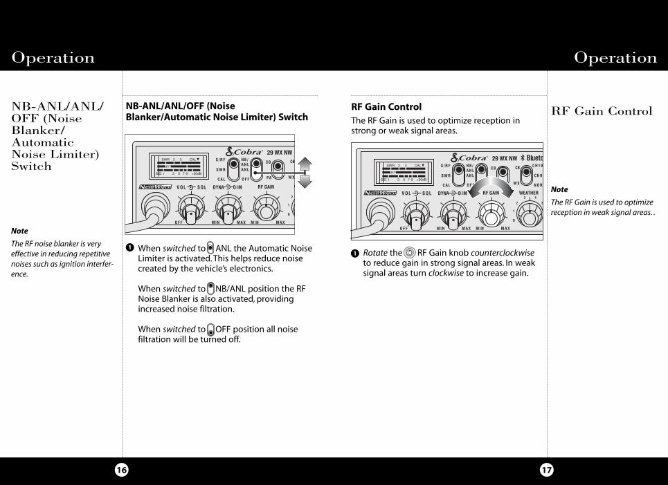
When switched to ANL the Automatic NoiseLimiter is activated.This helps reduce noisecreated by the vehicle’s electronics.
When switched to NB/ANL position the RFNoise Blanker is also activated, providingincreased noise filtration.
When switched to OFF position all noisefiltration will be turned off.
OperationOperation
1716
NB-ANL/ANL/OFF (NoiseBlanker/AutomaticNoise Limiter)Switch
RF Gain ControlRF Gain ControlThe RF Gain is used to optimize reception instrong or weak signal areas.
Note
The RF Gain is used to optimizereception in weak signal areas. .
Note
The RF noise blanker is veryeffective in reducing repetitivenoises such as ignition interfer-ence.
SIG 1 3 5 7 9 +30dB
2 3 CAL
RF
SWR
RF
S/RF
SWR
CAL
NB/ANLANL
OFF
CB
PA
MIN MAX MIN MAXOFF
VOL SQL
CB
WX
29 WX NW
WRF GAINDYNA DIM
1
2
Rotate the RF Gain knob counterclockwiseto reduce gain in strong signal areas. In weaksignal areas turn clockwise to increase gain.
SIG 1 3 5 7 9 +30dB
2 3 CAL
RF
SWR
RF
S/RF
SWR
CAL
NB/ANLANL
OFF
CB
PA
CH19
CH9
NOR
MIN MAX MIN MAXO FF
VOL SQL
CB
WX
29 WX NW
WEATHERRF GAINDYNA DIM
1
2 5
3 4
1
NB-ANL/ANL/OFF (NoiseBlanker/Automatic Noise Limiter) Switch
1
29WXNWBT_MANL.qx:29WXNWBT_MANL.qx 1/7/09 4:26 PM Page 16

Full clockwise rotation closes the gateallowing only very strong signals to enter.
Full counterclockwise rotation opens the“gate” allowing all signals in.
To achieve the Desired Squelch Setting (DSS),turn the Squelch control counterclockwiseuntil you hear noise. Now turn the controlclockwise just until the noise stops. This is theDSS setting.
Dimmer Switch
Setting SquelchSquelch is the “control gate” for incoming signals.
19
Dimmer Switch
18
Operation Operation
1
2
1
3
Rotate the Dimmer knob clockwise formaxi-mumbrightness;counter-clockwise forminimum
SIG 1 3 5 7 9 +30dB
2 3 CAL
RF
SWR
RF
S/RF
SWR
CAL
NB/ANLANL
OFF
CB
PA
CH19
CH9
NOR
MIN MAX MIN MAXOFF
VOL SQL
CB
WX
29 WX NW
R
WEATHERRF GAINDYNA DIM
7
1 6
2 5
3 4T BACK
NOISE
WEAK SIGNALS
MEDIUM SIGNALS
STRONG SIGNALS
GA
TE
CL
OS
ED
NOISE
WEAK SIGNALS
MEDIUM SIGNALS
STRONG SIGNALS
NOISE
WEAK SIGNALS
MEDIUM SIGNALS
STRONG SIGNALS
GA
TE
O
PE
N
NOISE
WEAK SIGNALS
MEDIUM SIGNALS
STRONG SIGNALS
NOISE
WEAK SIGNALS
MEDIUM SIGNALS
STRONG SIGNALS
GA
TE
Gate open
Gate set to Desired Squelch Setting (DSS)
Gate closed
SIG 1 3 5 7 9 +30dB
2 3 CAL
RF
SWR
RF
S/RF
SWR
CAL
NB/ANLANL
OFF
CB
PA
CH19
CH9
NOR
MIN MAX MIN MAXOFF
VOL SQL
CB
WX
29 WX NW
RX/TXWX
WEATHERRF GAINDYNA DIM
7
1 6
2 5
3 4
ANT
T BACK SWR CAL
SIG 1 3 5 7 9 +30dB
2 3 CAL
RF
SWR
RF
S/RF
SWR
CAL
NB/ANLANL
OFF
CB
PA
CH19
CH9
NOR
MIN MAX MIN MAXOFF
VOL SQL
CB
WX
29 WX NW
RX/TXWX
WEATHERRF GAINDYNA DIM
7
1 6
2 5
3 4
ANT
T BACK SWR CAL
Setting Squelch
SIG 1 3 5 7 9 +30dB
2 3 CAL
RF
SWR
RF
S/RF
SWR
CAL
NB/ANLANL
OFF
CB
PA
CH19
CH9
NOR
MIN MAX MIN MAXOFF
VOL SQL
CB
WX
29 WX NW
RX/TXWX
WEATHERRF GAINDYNA DIM
7
1 6
2 5
3 4
ANT
T BACK SWR CAL
Note
The Dimmer controls thebrightness of the front panel,signal strength meter andchannel display.
29WXNWBT_MANL.qx:29WXNWBT_MANL.qx 1/7/09 4:26 PM Page 18

Setting Dynamike®This controls the microphone sensitivity (outgoing audio level).
To Transmit
21
To Transmit Transmit
20
SettingDynamike®
Caution!
Be sure the antenna is properlyconnected to the radio beforetransmitting. Prolonged trans-mitting without an antenna, ora poorly matched antenna,could cause damage to thetransmitter.
Be sure to read the F.C.C. Rulesand Regulations included withthis unit before transmitting.
Operation Operation
1
Select desired channel.1
SIG 1 3 5 7 9 +30dB
2 3 CAL
RF
SWR
RF
S/RF
SWR
CAL
NB/ANLANL
OFF
CB
PA
CH19
CH9
NOR
MIN MAX MIN MAXOFF
VOL S Q L
CB
WX
29 WX NW
RX/TXWX
WEATHERRF GAINDYNA DIM
7
1 6
2 5
3 4
ANT
T BACK SWR CAL
Initially, set fully clockwise so that maxi-mum voice volume is available. Dynamikemay have to be reduced in some conditions.
SIG 1 3 5 7 9 +30dB
2 3 CAL
RF
SWR
RF
S/RF
SWR
CAL
NB/ANLANL
OFF
CB
PA
CH19
CH9
NOR
MIN MAX MIN MAXOFF
VOL SQL
CB
WX
29 WX NW
RX/TXWX
WEATHERRF GAINDYNA DIM
7
1 6
2 5
3 4
ANT
T BACK SWR CAL
Transmit
Push and holdmic button to transmit.Transmitter is now activated. When transmit-ting, hold the microphone two inches fromyour mouth and speak in a clear, normal voice.Release to receive.
1
PUSH &HOLD
29WXNWBT_MANL.qx:29WXNWBT_MANL.qx 1/7/09 4:26 PM Page 20
OperationOperation
RF Meter
2322
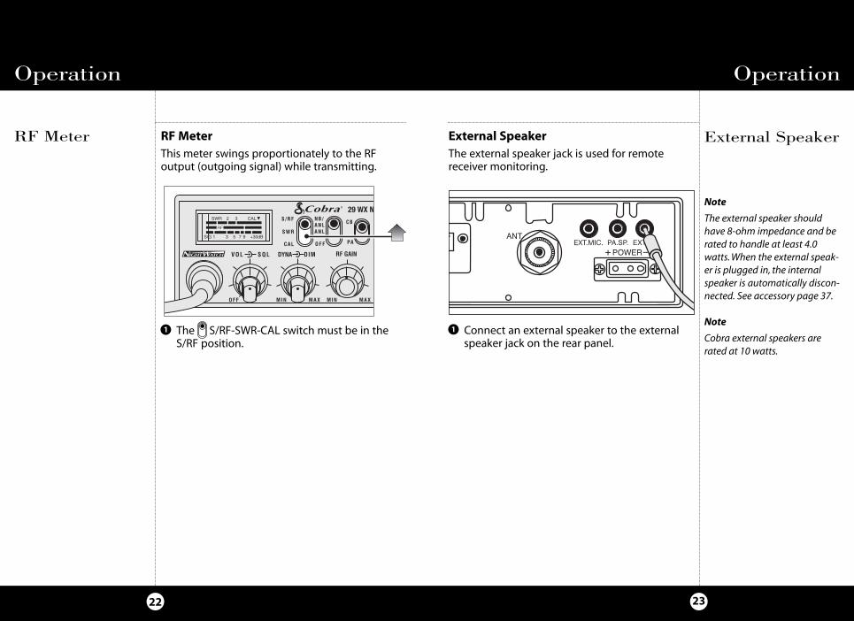
External SpeakerRF MeterThis meter swings proportionately to the RFoutput (outgoing signal) while transmitting.
External SpeakerThe external speaker jack is used for remotereceiver monitoring.
The S/RF-SWR-CAL switch must be in theS/RF position.
1
Note
The external speaker shouldhave 8-ohm impedance and berated to handle at least 4.0watts. When the external speak-er is plugged in, the internalspeaker is automatically discon-nected. See accessory page 37.
Note
Cobra external speakers arerated at 10 watts.
Connect an external speaker to the externalspeaker jack on the rear panel.
1
SIG 1 3 5 7 9 +30dB
2 3 CAL
RF
SWR
RF
S/RF
SWR
CAL
NB/ANLANL
OFF
CB
PA
MIN MAX MIN MAXOFF
VOL SQL
29 WX NW
RF GAINDYNA DIM
1
29WXNWBT_MANL.qx:29WXNWBT_MANL.qx 1/7/09 4:26 PM Page 22
OperationOperation
PA (PublicAddress)
2524
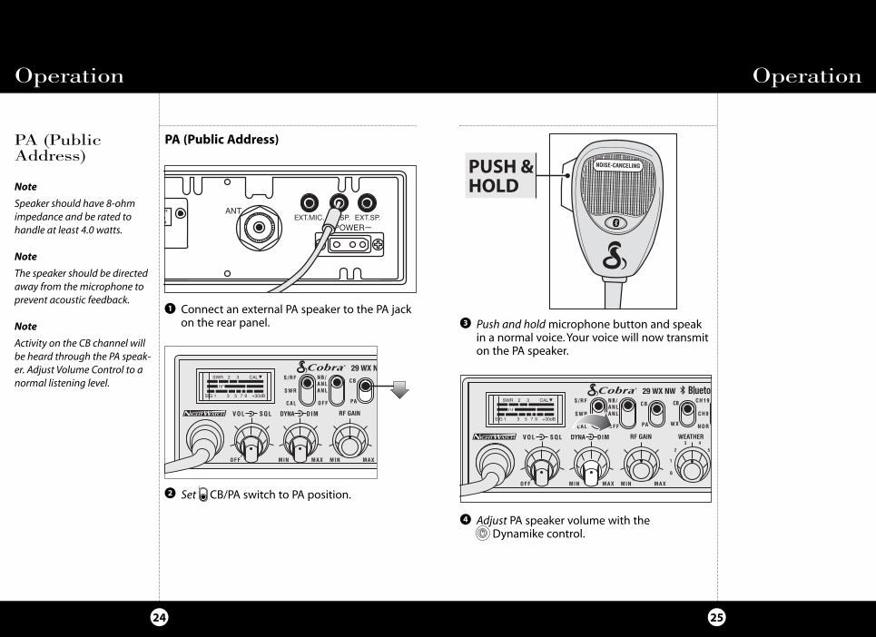
PA (Public Address)
Connect an external PA speaker to the PA jackon the rear panel.
Set CB/PA switch to PA position.
Push and holdmicrophone button and speakin a normal voice. Your voice will now transmiton the PA speaker.
Adjust PA speaker volume with the Dynamike control.
Note
Speaker should have 8-ohmimpedance and be rated to handle at least 4.0 watts.
Note
The speaker should be directedaway from the microphone toprevent acoustic feedback.
Note
Activity on the CB channel willbe heard through the PA speak-er. Adjust Volume Control to anormal listening level.
1
2
3
4
PUSH &HOLD
CH19
CH9
NOR
HI
WEATHER
1
2
3 4
OFF
SIG 1 3 5 7 9 +30dB
2 3 CAL
RF
SWR
RF
S/RF
SWR
CAL
NB/ANLANL
OFF
CB
PA
CH19
CH9
NOR
MIN MAX MIN MAXOFF
VOL SQL
CB
WX
29 WX NW
WEATHERRF GAINDYNA DIM
1
2
3 4 SIG 1 3 5 7 9 +30dB
2 3 CAL
RF
SWR
RF
S/RF
SWR
CAL
NB/ANLANL
OFF
CB
PA
CH19
CH9
NOR
MIN MAX MIN MAXOFF
VOL SQL
CB
WX
29 WX NW
RX/TXWX
WEATHERRF GAINDYNA DIM
7
1 6
2 5
3 4
ANT
T BACK SWR CAL
29WXNWBT_MANL.qx:29WXNWBT_MANL.qx 1/7/09 4:26 PM Page 24
OperationOperation
2726
WeatherInformation
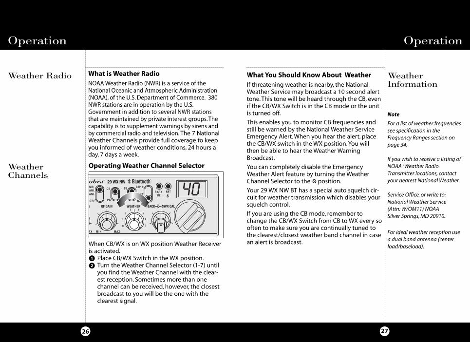
When CB/WX is on WX position Weather Receiveris activated.
Place CB/WX Switch in the WX position.Turn the Weather Channel Selector (1-7) untilyou find the Weather Channel with the clear-est reception. Sometimes more than onechannel can be received, however, the closestbroadcast to you will be the one with theclearest signal.
Operating Weather Channel Selector
SIG 1 3 5 7 9 +30dB
2 3 CAL
RF
SWR
RF
S/RF
SWR
CAL
NB/ANLANL
OFF
CB
PA
CH19
CH9
NOR
MIN MAX MIN MAXOFF
VOL SQL
CB
WX
29 WX NW
RX/TXWX
WEATHERRF GAINDYNA DIM
7
1 6
2 5
3 4
ANT
T BACK SWR CAL
Note
For a list of weather frequenciessee specification in theFrequency Ranges section onpage 34.
If you wish to receive a listing ofNOAA ‘Weather RadioTransmitter locations, contactyour nearest National Weather.
Service Office, or write to:National Weather Service(Attn: W/OM11) NOAASilver Springs, MD 20910.
For ideal weather reception usea dual band antenna (centerload/baseload).
What You Should Know About WeatherIf threatening weather is nearby, the NationalWeather Service may broadcast a 10 second alerttone. This tone will be heard through the CB, evenif the CB/WX Switch is in the CB mode or the unitis turned off.
This enables you to monitor CB frequencies andstill be warned by the National Weather ServiceEmergency Alert. When you hear the alert, placethe CB/WX switch in the WX position. You willthen be able to hear the Weather WarningBroadcast.
You can completely disable the EmergencyWeather Alert feature by turning the WeatherChannel Selector to the position.
Your 29 WX NW BT has a special auto squelch cir-cuit for weather transmission which disables yoursquelch control.
If you are using the CB mode, remember tochange the CB/WX Switch from CB to WX every sooften to make sure you are continually tuned tothe clearest/closest weather band channel in casean alert is broadcast.
Weather Radio
WeatherChannels
What is Weather RadioNOAAWeather Radio (NWR) is a service of theNational Oceanic and Atmospheric Administration(NOAA), of the U.S. Department of Commerce. 380NWR stations are in operation by the U.S.Government in addition to several NWR stationsthat are maintained by private interest groups. Thecapability is to supplement warnings by sirens andby commercial radio and television. The 7 NationalWeather Channels provide full coverage to keepyou informed of weather conditions, 24 hours aday, 7 days a week.
1
2
ø
29WXNWBT_MANL.qx:29WXNWBT_MANL.qx 1/7/09 4:26 PM Page 26
Temporary Mobile Set-Up
29
Base StationOperation(From 120V ACHouse Current)
TemporaryMobile Set-Up
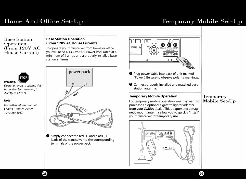
Temporary Mobile OperationFor temporary mobile operation you may want topurchase an optional cigarette lighter adapterfrom your COBRA dealer. This adapter and a mag-netic mount antenna allow you to quickly “install”your transceiver for temporary use.
Base Station Operation(From 120V AC House Current)To operate your transceiver from home or officeyou will need a 13.2 volt DC Power Pack rated at aminimum of 2 amps, and a properly installed basestation antenna.
Home And Office Set-Up
28
Warning! Do not attempt to operate thistransceiver by connecting itdirectly to 120V AC.
Note
For further information callCobra Customer Service1.773.889.3087.
1
Connect properly installed and matched basestation antenna.
Simply connect the red (+) and black (-) leads of the transceiver to the correspondingterminals of the power pack.
Plug power cable into back of unit marked“Power”. Be sure to observe polarity markings.
2
3
+ —
29WXNWBT_MANL.qx:29WXNWBT_MANL.qx 1/7/09 4:26 PM Page 28

How Your CB Can Serve YouHow Your CB Can Serve You
3130
The FCC gives these examples of permitted andprohibited messages for channel 9. These areonly guidelines and not all-inclusive:
Permitted Example MessageYes “Tornado sighted six miles north
of town.”
No “Post number 10. No tornado sighted.”
Yes “Out of gas on I-95 at mile marker 211.”
No “Out of gas in my driveway.”
Yes “Four car accident on I-94 at Exit 11. Send police and ambulance.”
No “Traffic moving smoothly on I-94.”
Yes “Weather Bureau has issued thunderstorm warning. Bring sailboat into port.”
No “Attention motorists. Weather Bureau advises snow tomorrow will accumulate 4 to 6 inches.”
Yes “Fire in building at 539 Main, Evanston.”
No “Halloween patrol number 3. All quiet.”
1. Set to channel 9 for emergenciesBe sure antenna is properly connected.
2. CB Distress DataWhen transmitting an emergency, you shouldrequest a “REACT BASE” and provide the CB distress data (called CLIP):
C all Sign Identify yourself.L ocation Be exact.I njuries Number. Type. Trapped?P roblem Give details and help needed.
Transmit CLIP repeatedly so any monitor can assist.
Channel 9EmergencyMessages
Note
If no response on channel 9, try channels 19 or 14.
• Warn of traffic problems• Provide weather and road data• Provide help in event of an emergency • Provide direct contact with home or office • Assist police by reporting erratic drivers• Get “local information” to find destination• Communicate with family and friends• Suggest spots to eat and sleep• Keep you alert while traveling
A Few Rules You Should KnowA. Conversations cannot last more than 5 minutes
with another station. A one minute break isrequired to let others use the channel.
B. You cannot blast others off the air by use of illegally amplified transmitters or illegally high antennas.
C. You cannot use CB to promote illegal activities.D. Profanity is not allowed.E. You may not transmit music with a CB.F. Selling of merchandise and/or services is prohibited.
A Few Rules You Should Know
29WXNWBT_MANL.qx:29WXNWBT_MANL.qx 1/7/09 4:26 PM Page 30
How Your CB Can Serve YouHow Your CB Can Serve You
3332
Code Meaning
10-29 Time is up for contact
10-30 Does not conform to FCC rules
10-33 Emergency traffic
10-34 Trouble at this station
10-35 Confidential information
10-36 Correct time is
10-37 Wrecker needed at
10-38 Ambulance needed
10-39 Message delivered
10-41 Turn to channel
10-42 Traffic accident at
10-43 Traffic tie up at
10-44 Have a message for
10-45 All units within range please report
10-50 Break channel
10-60 What is next message number?
10-62 Unable to copy. Use phone
10-63 Net directed to
10-64 Net clear
10-65 Awaiting your next message/assignment
10-67 All units comply
10-70 Fire at
10-71 Proceed, transmission in sequence
10-77 Negative contact
10-81 Reserve hotel room for
10-82 Reserve room for
10-85 My address is
10-91 Talk closer to mic
10-93 Check my frequency on this channel
10-94 Give me a long count
10-99 Mission completed, all units secure
10-200 Police needed at
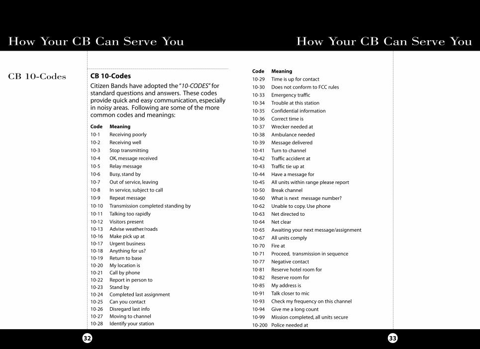
CB 10-CodesCitizen Bands have adopted the “10-CODES” forstandard questions and answers. These codesprovide quick and easy communication, especiallyin noisy areas. Following are some of the morecommon codes and meanings:
Code Meaning
10-1 Receiving poorly
10-2 Receiving well
10-3 Stop transmitting
10-4 OK, message received
10-5 Relay message
10-6 Busy, stand by
10-7 Out of service, leaving
10-8 In service, subject to call
10-9 Repeat message
10-10 Transmission completed standing by
10-11 Talking too rapidly
10-12 Visitors present
10-13 Advise weather/roads
10-16 Make pick up at
10-17 Urgent business
10-18 Anything for us?
10-19 Return to base
10-20 My location is
10-21 Call by phone
10-22 Report in person to
10-23 Stand by
10-24 Completed last assignment
10-25 Can you contact
10-26 Disregard last info
10-27 Moving to channel
10-28 Identify your station
CB 10-Codes
29WXNWBT_MANL.qx:29WXNWBT_MANL.qx 1/7/09 4:26 PM Page 32
29 WX NW BT SpecificationsFrequency Ranges
3534
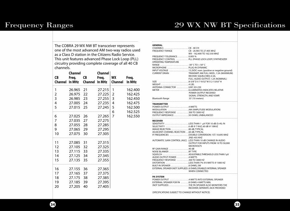
GENERALCHANNELS . . . . . . . . . . . . . . . . . . . . . . . . CB - 40 CH FREQUENCY RANGE CB - 26.965 TO 27.405 MHZ
WX - 162.400 TO 162.550 MHZFREQUENCY TOLERANCE . . . . . . . . . . . 0.005 %FREQUENCY CONTROL . . . . . . . . . . . . PLL (PHASE LOCK LOOP) SYNTHESIZEROPERATING TEMPERATURE RANGE . . . . . . . . . . . . . . . . . . . . . . . . . . . . -30° C TO + 50° CMICROPHONE . . . . . . . . . . . . . . . . . . . . . PLUG-IN DYNAMICINPUT VOLTAGE . . . . . . . . . . . . . . . . . . . 13.2VDC nom. (positive or negative ground) CURRENT DRAIN TRANSMIT: AM FULL MOD., 1.5A (MAXIMUM)
RECEIVE: SQUELCHED, 0.3A; FULL AUDIO OUTPUT, 1.2A (NOMINAL)
SIZE . . . . . . . . . . . . . . . . . . . . . . . . . . . . . .8-5/8” D X 7-9/32” W X 2-13/63” HWEIGHT . . . . . . . . . . . . . . . . . . . . . . . . . . . .4 LBS.ANTENNA CONNECTOR . . . . . . . . . . . .UHF; SO-239METER . . . . . . . . . . . . . . . . . . . . . . . . . . . . .ILLUMINATED; INDICATES RELATIVE
POWER OUTPUT RECEIVED SIGNAL STRENGTH, AND VSWR
Bluetooth Range 33' (10 meters)
TRANSMITTERPOWER OUTPUT . . . . . . . . . . . . . . . . . . .4 WATTSMODULATION . . . . . . . . . . . . . . . . . . . . .AM (AMPLITUDE MODULATION)FREQUENCY RESPONSE . . . . . . . . . . . .300 TO 3000 HZOUTPUT IMPEDANCE . . . . . . . . . . . . . . .50 OHMS, UNBALANCED
RECEIVERSENSITIVITY . . . . . . . . . . . . . . . . . . . . . . . .LESS THAN 1 µV FOR 10 dB (S+N) /NSELECTIVITY . . . . . . . . . . . . . . . . . . . . . . .6 dB @ 7 KHZ, 60 dB @ 10KHZIMAGE REJECTION . . . . . . . . . . . . . . . . . .80 dB, TYPICALADJACENT-CHANNEL REJECTION . . .60 dB, TYPICALIF FREQUENCIES . . . . . . . . . . . . . . . . . . .DOUBLE CONVERSION: 1ST: 10.695 MHZ
2ND: 455 KHZAUTOMATIC GAIN CONTROL (AGC) .LESS THAN 10 dB CHANGE IN AUDIO
OUTPUT FOR INPUTS FROM 10 TO 50,000 MICROVOLTS
RF GAIN RANGE . . . . . . . . . . . . . . . . . . . .40 dBNOISE BLANKER . . . . . . . . . . . . . . . . . . . .RF TYPESQUELCH . . . . . . . . . . . . . . . . . . . . . . . . . .ADJUSTABLE; THRESHOLD LESS THAN 1µVAUDIO OUTPUT POWER . . . . . . . . . . . .4 WATTSFREQUENCY RESPONSE . . . . . . . . . . . .300 TO 3000 HZDISTORTION . . . . . . . . . . . . . . . . . . . . . . .LESS THAN 7% @3 WATTS @ 1000 HZBUILT-IN SPEAKER . . . . . . . . . . . . . . . . . .8 OHMS, 5WEXTERNAL SPEAKER (NOT SUPPLIED) .8 OHMS; DISABLES INTERNAL SPEAKER
WHEN CONNECTED
PA SYSTEMPOWER OUTPUT . . . . . . . . . . . . . . . . . . .4 WATTS INTO EXTERNAL SPEAKEREXTERNAL SPEAKER FOR PA . . . . . . . .8 OHMS 4 WATTS MIN.(NOT SUPPLIED) . . . . . . . . . . . . . . . . . . . .THE PA SPEAKER ALSO MONITORS THE
RECEIVER; SEPARATE JACK PROVIDED
(SPECIFICATIONS SUBJECT TO CHANGE WITHOUT NOTICE)
The COBRA 29 WX NW BT transceiver representsone of the most ad vanced AM two-way radios usedas a Class D station in the Citizens Radio Service.This unit features advanced Phase Lock Loop (PLL) circuitry providing complete cov er age of all 40 CBchan nels.
1 26.965 21 27.215 1 162.4002 26.975 22 27.225 2 162.4253 26.985 23 27.255 3 162.4504 27.005 24 27.235 4 162.4755 27.015 25 27.245 5 162.500
6 162.5256 27.025 26 27.265 7 162.5507 27.035 27 27.2758 27.055 28 27.2859 27.065 29 27.29510 27.075 30 27.305
11 27.085 31 27.31512 27.105 32 27.32513 27.115 33 27.33514 27.125 34 27.34515 27.135 35 27.355
16 27.155 36 27.36517 27.165 37 27.37518 27.175 38 27.38519 27.185 39 27.39520 27.205 40 27.405
Channel ChannelCB Freq. CB Freq. WX Freq.Channel In MHz Channel In MHz Channel In MHz
29WXNWBT_MANL.qx:29WXNWBT_MANL.qx 1/7/09 4:26 PM Page 34

Optional Accessories
3736
COBRA ELECTRONICS CORPORATION warrants that itsCOBRA CB Radios, and the com po nent parts thereof, willbe free of defects in workmanship and materials for periodof two (2) years from the date of first consumer purchase.This war ran ty may be enforced by the first consumer pur chas er, pro vid ed that the product is utilized within the U.S.A.
COBRA will, without charge, repair or replace, at its option,de fec tive CB radios, products or com po nent parts uponde liv ery to the COBRA factory Service Department, ac com -pa nied by proof of the date of first consumer pur chase,such as a du pli cat ed copy of a sales receipt.
You must pay any initial shipping charges required to shipthe product for warranty service, but the return chargeswill be at Cobra's expense, if the product is repaired orreplaced under warranty.
Exclusions: This limited warranty does not apply; 1) to anyproduct dam aged by accident; 2) in the event of misuse orabuse of the product or as a result of un au tho rized alter-ations or repairs; 3) if the serial number has been altered,defaced or re moved; 4) if the owner of the product residesoutside the U.S.A.
All implied warranties, including war ran ties of mer chant abil i ty and fitness for a par tic u lar purpose are limited in duration to the length of this warranty.COBRA shall not be liable for any incidental, con se -quen tial or oth er dam ag es; including, without lim i ta -tion, damages re sult ing from loss of use or cost of in stal -la tion.
Some states do not allow limitations on how long animplied warranty lasts and/or do not allow the ex clu -sion or limitation of incidental or con se quen tial dam -ag es, so the above lim i ta tions may not apply to you.
Cobra ElectronicsCorporation
6500 West Cortland StreetChicago, Illinois 60707www,cobra.com
Limited Two Year Warranty
Replacement DC Power Cord
For in vehicle use426-002-N-001
Replacement MountingBracket
For in vehicle use251-353-9-001
Replacement Thumb Screws
For in vehicle use634-081-9-001
Replacement MicrophoneBracket
For in vehicle use741-080-9-001
21” Base Loaded MagnetMount Antenna
HG A1000
38” Base Loaded MagnetMount Antenna
HG A1500
Replacement ExternalBluetooth Microphone
MNA MIC
Dynamic External Speaker
HG S100
Noise Canceling External Speaker
HG S300
Noise CancelingWith Talk BackExternal Speaker
HG S500
You can find quality Cobra products and accessories at your local Cobra dealer, or in theU.S.A., you can order directly from Cobra. See ordering info on page 38.
29WXNWBT_MANL.qx:29WXNWBT_MANL.qx 1/7/09 4:26 PM Page 36
3938
Optional Accessories
Ordering From U.S.A.Call 773-889-3087 for pricing or visit www.cobra.com.
For Credit Card OrdersCall 773-889-3087 [Press one from the main menu] 8:00 a.m. to 5:30 p.m. Central Time, Monday through Friday.
Make Check or Money Order Payable ToCobra Electronics, Attn: Accessories Dept., 6500 West Cortland Street, Chicago, IL 60707 U.S.A.
To Order OnlinePlease visit our website: www.cobra.com
Notes
29WXNWBT_MANL.qx:29WXNWBT_MANL.qx 1/7/09 4:26 PM Page 38