for the warmest of welcomes - swept away chimney...
TRANSCRIPT

For the warmest of welcomes
OWNERS MANUAL
A comprehensive guide to the installation, assembly, operation and maintenance for all Villager woodburning stoves
‘A’ RANGE
‘B’ RANGE
‘C’ RANGE
FLATMATE
KITCHENER
ELITE RANGE
BERKLEY RANGE
BAYSWATER RANGE
CHELSEA SOLO/DUO
and all Villager Multi-Fuel Stoves
approved

Thank you for buying a Villager Stove
Since 1979 we have specialised in the design and manufacture of high performance stoves, and over the years have built an enviable reputation for the quality, reliability and fuel efficiency of our products. This has been achieved through combining the latest manufacturing technology with traditional engineering skills and craftsmanship.
Please read through this booklet carefully before you start
We have tried to make these instructions as straightforward and comprehensive as possible. If you are unsure on any aspect of the installation or operation please seek expert advice from your qualified heating engineer, your Villager dealer, or by calling out technical helpline on 0844 8475107 Even if you have had your stove professionally installed we recommend that you read all the sections to familiarise yourself with every aspect of the stoves installation and operation. Correctly installed and operated, your Villager stove will give years of faithful service and always provide “The Warmest of welcomes” Please keep this manual for future reference.
SECTION 1 Important information Please read this section before the installation is started Pages 3, 4 & 5
SECTION 2 Stove installation Pages 6, to 9
SECTION 3 Lighting and maintenance Please read this section before you light the stove. It includes information on safety and maintenance. Pages 10, to 12
SECTION 4 Operating the Stove Pages 13, to 16
The last word Pages 17
Villager Fireguard Guarantee Pages 17
Useful numbers to record Pages 17
2
C O N T E N T S

SECTION 1
Important Information
SECTION 1 3
Please read section carefully before the installation is started
INSTALLER RESPOSIBILITY Under the Health & Safety at Work act 1974 all installation work must be carried out in such a way as to ensure that there is not danger to the installer or to others
ASBESTOS AWARENESS Particular attention should be given to the possibility of disturbing asbestos in existing installations. Asbestos should only be removed by a registered Specialist.
THE USE OF FIRE CEMENT Attention should be given to caustic nature of fire cement it is advised that protection gloves are worn, and any fire cement that comes into contact with skin is washed off thoroughly with water without delay. Care should be taken not to get fire cement on the body of the stove.
INSTALLATION COMPLIANCE
Stoves The stove should be installed in accordance with:
BS8303: Code of Practice for the installation of domestic heating and cooking appliances burning solid mineral fuels BS6461: Installation of chimneys and flues for domestic appliances burning solid fuels including wood and peat
All solid fuel and woodburning stoves must be installed by a competent person, in compliance with all National and local Building Regulations and codes of practice, including European standards where appropriate. HETAS® maintains a list of registered solid fuel installers we will be pleased to supply details if necessary. Many Villager dealers have their own installers or should be able to recommend a suitable installer.
An extractor fan must not be fitted in the same room as the stove as it can stop the chimney from drawing correctly.
The stove must not be modified in any way without our express permission, any unauthorised modification will invalidate the guarantee.
If you are installing a stove in a boat, caravan or mobile home or other mobile structure, it is very important to realise the potential fire risks present in such installations.
1, The stove must stand on a non combustible hearth which is suitably insulated from any combustible materials
2, The stove must be suitably insulated from materials around and above the stove.
3, The stove pipe must be suitably insulated any combustible material in particular where the flue passes though the roof. Special -
fittings are available from ships chandlers and caravan dealers for roof penetration
4, The stove and the flue pipe must be securely fixed in position.
5, Ventilation must be provided with fixed permanently open vents
6, Store flammable liquids, gas bottles, aerosols materials, etc, well away from the stove
7, The stove should never be alight when the boat /caravan is in motion - the stove must be cool or cold, with doors securely shut.
NOTE: A useful insulating material for such installations is ceramic fibre board, which can be sandwiched between a fireproof facing board and the combustible material - but note that it is not suitable for use in damp or wet situations. This material is available in various thicknesses - and has excellent thermal insulation properties.
The Chimney
The chimney used should be in accordance with: BS 6461: Installation of chimneys and flues for domestic appliances burning solid fuel, including wood and peat. This type of chimney is often referred to as Class 1.
The chimney should not be less than 4 metres (13ft) in length, measured vertically from the top of the stove to the chimney and should terminate at least 1 metre above roof level
Note: Do not include any horizontal runs in rear flue entry connection to the vertical length of chimney
The flue connected to the stove must be at least the same diameter as the outlet on the stove, 152/6” or 127mm/5” on series 2 and Chelsea Solo/Duo.
Please note: If a liner is to be installed it must be a minimum of 152mm/6” diameter if wood is the fuel being used. Prior to installation, the chimney must be swept and examined for soundness and suitability. Chimneys with large cross sectional area may not be suitable unless an insulated solid fuel liner is fitted. Any faults must be rectified prior to stove installation. If in doubt seek expert advice from your Villager dealer/installer. Prefabricated block chimneys or twin walled stainless steel flues , manufactured to BS4543 can be used, but must be installed in accordance with the manufacturers instructions and building regulations.
Your Villager stove is not suitable for connection to a shared chimney, it will not draw properly.
Flue Damper We can supply a flue damper kit as an optional extra to the appliance, which will give additional control over the flue draught and therefore the burn rate of the appliance. A damper be beneficial in installations Where a high flue draught is present and in cases

4 SECTION 1
Slow burning for log periods is envisaged. The damper kits are available for both 125mm(5”) and 150mm(6”) diameter flues.
It should be noted that in some cases of high flue draught– it may be necessary to employ additional means of reducing the flue draught to allow the stove to burn slowly. Other means such as a restrictive chimney cowl, or a flue draught stabiliser may be required in these cases.
Flue connections.
The stove must be connected to the chimney using the specified size flue pipe for the stove, i.e. 152mm(6”) for all stoves except the Series 2 and Chelsea Solo/Duo stoves, which have a flue size of 127mm(5”). The pipe should be suitably sealed to the stove and chimney, using flexible non combustible rope and fire cement.
Specification for the hearth and the stove location
Please refer to the table below for a guideline weight of each appliance, it is essential that the stove is only installed on a floor with adequate load bearing capacity to support the combined weight of the hearth and stove. If there is any doubt consult an expert, as it may be necessary to incorporate a load bearing plate to suitably reinforce the floor and provide sufficient support
Fig. 1 Fig. 2
Fig. 3 Fig. 4
When the flue pipe extends into the chimney, voids must be filled and flaunched, i.e. Sloped inwards towards the top, to ensure all deposits can be cleared when the chimney is swept. Access for cleaning the flue should be provided. This can be achieved with a cleaning door in the flue pipe, or by a soot door installed into the chimney that allows easy access to the flue pipe. A flue should not have more than two 45º bends, except for rear flue applications where a 90º bend may be used. The horizontal run from the back outlet should not exceed 150mm. Typical installations are shown in Figs 1 to 4.
Stove Type Weight Kg
AH Woodburner 99
AL Woodburner 96
A Flat Woodburner 85
BH Woodburner 73
BL Woodburner 68
Flatmate Woodburner 67
Kitchener Woodburner 63
Berkley Flat Woodburner 78
Berkley Low Woodburner 82
C Flat Woodburner 60
C Low Woodburner 66
Chelsea Solo/Duo 62
Chelsea Solo/Duo with Low Canopy 70
Chelsea Solo/Duo with High Canopy 74
Bayswater Flat Multifuel 80
Bayswater Low Multifuel 85
Bayswater High Multifuel 89
Elite Flat Multifuel 95
Elite Low Multifuel 100
Elite High Multifuel 104
The stove should be installed on a solid non - combustible hearth, at least 125mm thick, this depth may include the thickness of any solid non-combustible floor under the hearth. The hearth should extend 300mm in front of the stove, and 150mm on either side and to the rear. The width of the hearth can be less provided it extends to suitable heat resistance or non combustible walls. A stove with bolt holes in front feet or with angle brackets bolted to the integral feet should be fixed to the hearth using suitable bolts (not supplied) Fire recesses must be constructed from non -combustible material. The minimum clearance between the stove and the recess wall should be 75mm
Note: when installing multi-fuel stoves, which have a riddle mechanism, remember that clearance will be required on the right hand side of the stove (if the stove is recessed) in order to operate the riddling tool.
SECTION 1 5
The clearance around the stove to any non-combustible materials should be 75mm either side, 150mm above and 25mm from the rear wall. These are the ideal recommended measurements, however if in doubt of the integrity of any of the surfaces (i.e. Marble, tiles, etc) clad with heat resistant materials. The clearance from the flue pipe to any wooden beam, such as may be found in an inglenook must be at least 3 times the flue diameter, i.e. If the flue diameter is 152mm (6”) then the clearance must be at least 456mm (18”) unless the wood is shielded with non combustible materials
Minimum clearance to combustible materials
Ventilation
No purpose provided ventilation is required for stoves rated 5kw or less. For each kw above 5kW, 550mm² of fixed ventilation is required - eg. a stove rated at 8kW will require 3 x 550mm² = 1650mm² of fixed ventilation.
The Installer should always consult the current Building Regulations when either a new installation or an upgrade of an existing installation is undertaken
The vent should ideally be sited close to the stove to prevent draughts.
Where there is more than one appliance installed in the same room, the ventilation requirement for each individual appliance must be added together to give the total ventilationrequirement for the room. i.e. If one appliance reqires 550mm² and another requires 1650mm², a total of 2200mm² of ventilation must be supplied. The ventilation may be provided by one or more vents, care must be taken when siting the vents to avoid draughts and also to prevent accidental blockage to the air supply.
Note: The fitting of an extractor fan in the same room as the appliance is not permitted. An extractor fan installed in an adjacent room may adversely affect the chimney operation and is not advised. If you are in any doubt about the ventilation requirements consult a HETAS® approved solid fuel engineer
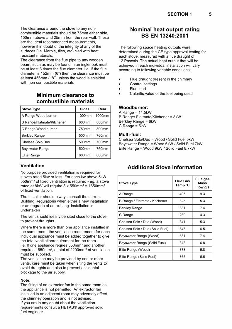
Nominal heat output rating BS EN 13240:2001
The following space heating outputs were determined during the CE type approval testing for each stove, measured with a flue draught of 12 Pascals. The actual heat output that will be achieved in each individual installation will vary according to following variable conditions:
Flue draught present in the chimney
Control settings
Flue load
Calorific value of the fuel being used
Woodburner: A Range = 14.5kW B Range/ Flatmate/Kitchener = 8kW Berkley Range = 6kW C Range = 5kW
Multi-fuel: Chelsea Solo/Duo = Wood / Solid Fuel 5kW Bayswater Range = Wood 6kW / Solid Fuel 7kW Elite Range = Wood 9kW / Solid Fuel 8.7kW
Additional Stove Information
Stove Type Sides Rear
A Range Wood burner 1000mm 1000mm
B Range/Flatmate/Kitchener 600mm 800mm
C Range Wood burner 750mm 800mm
Berkley Range 500mm 760mm
Chelsea Solo/Duo 500mm 700mm
Bayswater Range 500mm 760mm
Elite Range 600mm 800mm
Stove Type Flue Gas Temp ºC
Flue gas Mass
Flow g/s
A Range 406 9.3
B Range / Flatmate / Kitchener 325 5.3
Berkley Range 331 7.4
C Range 260 4.3
Chelsea Solo / Duo (Wood) 341 5.3
Chelsea Solo / Duo (Solid Fuel) 348 6.5
Bayswater Range (Wood) 331 7.4
Bayswater Range (Solid Fuel) 343 6.8
Elite Range (Wood) 378 5.8
Elite Range (Solid Fuel) 366 6.6
6 SECTION 2 SECTION 2
Stove Installation
Unpacking the stove
Take care in unpacking the stove from the cardboard box and wooden pallet to avoid any staples that may protrude from the wood. We suggest you open out the bow to use as a base, this will avoid possible damage to the floor. Please don't let children play with the polythene wrapper. The only tool you should need for assembly is a 13mm spanner, although it may be helpful to have a light hammer to hand as you will see later.
Stove Assembly
All stoves with bolt on legs
Fasten the door/s shut and carefully lay the stove on its back. The larger stoves are heavy - get some help if necessary. Gently open the door/s and rest them back against the hinges. Do not let the door/s fall back as this could damage both the door/s and hinges. Fit a leg to each corner by passing the bolt (provided) down though the stove base and locate it in the slot cut in each leg. Fasten with the washer and nut (also provided) using a 13mm spanner. Carefully close and refasten the door/s and stand the stove upright.
Boiler cut-outs
On the rear of the stove there will be 2 or in some cases 3 part cut holes to enable boiler installation. If the stove is to be used as a room heater without a boiler, rub some fire cement into the pre-cut slots on both sides of the stove to seal them effectively
Fitting the flue collar
PLEASE NOTE: No stoves are supplied with a flue damper as standard but one can be purchased from you Villager dealer. To fit a damper, 2 holes need to be drilled in our existing flue collar, but for the Chelsea range this needs to be fitted into the flue pipe.
Having decided on the flue exit position, i.e. top or rear, the flue collar and the hotplate / blanking plate/s can be fitted in position. Apply a layer of fire cement all around the flanges of the collar and the hotplate / blanking plate/s. Locate the collar, turn anti-clockwise into the desired position and allow the fire cement to set, locking the collar in place.
NOTE: The Wood burning „A‟ Flat must only be flued from the centre aperture.
Flue connection
The stove can now be placed in position and the flue connected to the chimney. All the flue joints must be sealed with fire cement to form a good seal.
Installing the internal fittings
The fitting of all internal components, including the brick layout, is shown in the detailed assembly instructions given for each model. Please note that the bricks themselves are not numbered - the numbering shown in each diagram is simply to indicate the right order for fitting them in position. NOTE: The bricks are fitted loose, do not cement them in position, any small gaps should be allowed to fill with ash when the stove is used.
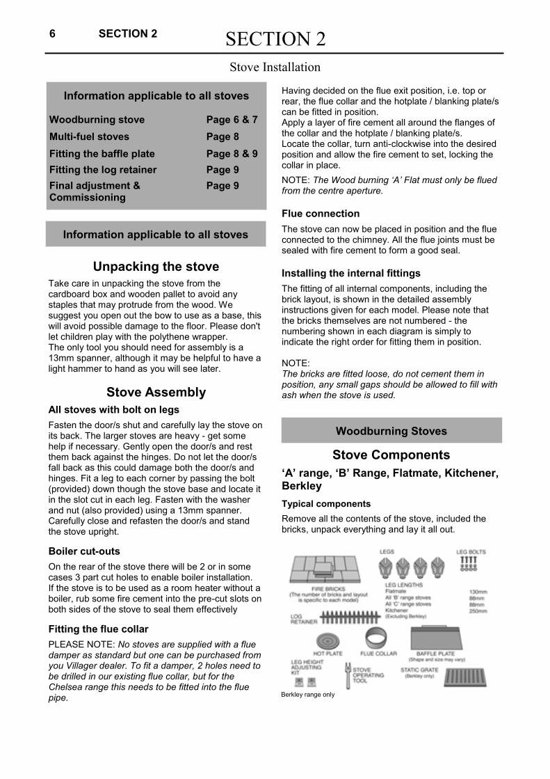
Stove Components
‘A’ range, ‘B’ Range, Flatmate, Kitchener, Berkley
Typical components
Remove all the contents of the stove, included the bricks, unpack everything and lay it all out.
Information applicable to all stoves Woodburning stove Page 6 & 7
Multi-fuel stoves Page 8
Fitting the baffle plate Page 8 & 9
Fitting the log retainer Page 9
Final adjustment & Page 9 Commissioning
Information applicable to all stoves
Woodburning Stoves
Berkley range only
SECTION 2 7
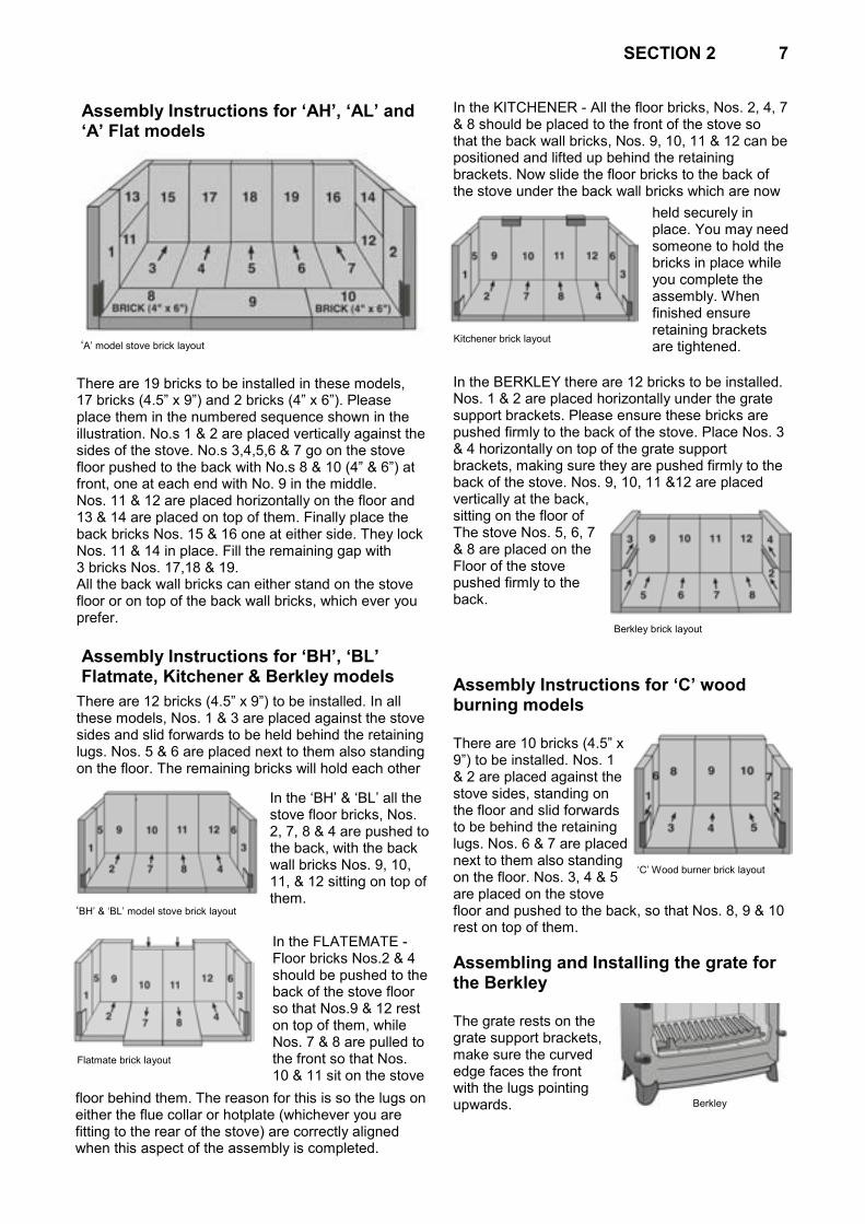
Assembly Instructions for ‘AH’, ‘AL’ and ‘A’ Flat models
There are 19 bricks to be installed in these models, 17 bricks (4.5” x 9”) and 2 bricks (4” x 6”). Please place them in the numbered sequence shown in the illustration. No.s 1 & 2 are placed vertically against the sides of the stove. No.s 3,4,5,6 & 7 go on the stove floor pushed to the back with No.s 8 & 10 (4” & 6”) at front, one at each end with No. 9 in the middle. Nos. 11 & 12 are placed horizontally on the floor and 13 & 14 are placed on top of them. Finally place the back bricks Nos. 15 & 16 one at either side. They lock Nos. 11 & 14 in place. Fill the remaining gap with 3 bricks Nos. 17,18 & 19. All the back wall bricks can either stand on the stove floor or on top of the back wall bricks, which ever you prefer.
Assembly Instructions for ‘BH’, ‘BL’ Flatmate, Kitchener & Berkley models
There are 12 bricks (4.5” x 9”) to be installed. In all these models, Nos. 1 & 3 are placed against the stove sides and slid forwards to be held behind the retaining lugs. Nos. 5 & 6 are placed next to them also standing on the floor. The remaining bricks will hold each other
In the KITCHENER - All the floor bricks, Nos. 2, 4, 7 & 8 should be placed to the front of the stove so that the back wall bricks, Nos. 9, 10, 11 & 12 can be positioned and lifted up behind the retaining brackets. Now slide the floor bricks to the back of the stove under the back wall bricks which are now
In the BERKLEY there are 12 bricks to be installed. Nos. 1 & 2 are placed horizontally under the grate support brackets. Please ensure these bricks are pushed firmly to the back of the stove. Place Nos. 3 & 4 horizontally on top of the grate support brackets, making sure they are pushed firmly to the back of the stove. Nos. 9, 10, 11 &12 are placed vertically at the back, sitting on the floor of The stove Nos. 5, 6, 7 & 8 are placed on the Floor of the stove pushed firmly to the back.
Assembly Instructions for ‘C’ wood burning models There are 10 bricks (4.5” x 9”) to be installed. Nos. 1 & 2 are placed against the stove sides, standing on the floor and slid forwards to be behind the retaining lugs. Nos. 6 & 7 are placed next to them also standing on the floor. Nos. 3, 4 & 5 are placed on the stove floor and pushed to the back, so that Nos. 8, 9 & 10 rest on top of them.
Assembling and Installing the grate for the Berkley The grate rests on the grate support brackets, make sure the curved edge faces the front with the lugs pointing upwards.
„A‟ model stove brick layout
„BH‟ & „BL‟ model stove brick layout
In the „BH‟ & „BL‟ all the stove floor bricks, Nos. 2, 7, 8 & 4 are pushed to the back, with the back wall bricks Nos. 9, 10, 11, & 12 sitting on top of them.
In the FLATEMATE - Floor bricks Nos.2 & 4 should be pushed to the back of the stove floor so that Nos.9 & 12 rest on top of them, while Nos. 7 & 8 are pulled to the front so that Nos. 10 & 11 sit on the stove
floor behind them. The reason for this is so the lugs on either the flue collar or hotplate (whichever you are fitting to the rear of the stove) are correctly aligned when this aspect of the assembly is completed.
held securely in place. You may need someone to hold the bricks in place while you complete the assembly. When finished ensure retaining brackets are tightened.
Kitchener brick layout
Flatmate brick layout
Berkley brick layout
„C‟ Wood burner brick layout
Berkley

8 SECTION 2
Woodburning Stoves
Stove Components Bayswater, Chelsea, Duo/Solo & Elite
Stoves
Typical Components These models are supplied with the grate, riddle mechanism and bricks already in place. Do not remove them when unpacking the remaining components.
NOTE 1: Although the grate and bricks are already in place, we have included assembly instructions so they can be replaced correctly, should you ever need to remove any of these components for maintenance purposes.
NOTE 2: The leg height adjusting kit should only be used to balance the stove if the surface of the hearth is slightly uneven. Attach one bracket to the inside of each rear leg of the stove as shown in the drawing, with the nut on the inside, and adjust the height until all four legs sit squarely on the hearth, the holes in the front of the bracket should be used to bolt the stove to the hearth.
Assembling and Installing the grate for the Bayswater, Chelsea Duo/Solo & Elite
Place the grate casting on the floor in front of the stove, not inside the stove at this stage, with the
the rocker arm is swung into its highest position. Lower the grate on to the grate bar supports, making sure all the riddle bars engage with the rocker arm. This is most important as the riddle will not otherwise work. To fit the ash pan slid under the grate assembly.
Brick Assembly Instructions For Bayswater, Chelsea Duo/Solo & Elite
In the Bayswater there are 4 bricks to be installed. Nos. 1 & 2 (4.5” x 9”) are placed horizontally on top of the grate, one against each side wall. Nos. 3 & 4 (6” x 9”) are placed horizontally at the back of the stove on top of the grate. Fit these after the grate is in place.
In the Chelsea Duo/Solo there are 5 bricks to be installed Nos. 1 & 2 placed horizontally along each sidewall of the stove after the grate is in place. Nos. 3, 4, & 5 are placed vertically along the back wall behind the grate and resting on the stove floor.
In the Elite there are 5 bricks to be installed. Nos. 1 & 2 (4.5” x 9”) are to be placed first on top of the grate. Then Nos. 3, 4, & 5 (6” x 9”) go along to the back, again on top of the grate, making sure the centre brick is horizontal and the 2 outside bricks are vertical.
Kitchener There are two baffle plate retaining lugs on each side of the stove, and one in the middle The baffle plate should be slid into position under the flue outlet, not under the hotplate.
Note: If the flue does not draw as well as you would like, the baffle plate can be removed.
Leg height adjustment
Bayswater brick layout
cut-outs or overhang to the rear. Fit the riddle bars into the grate casting with the longer, plain end first, then move them back so they are positioned centrally in the grate. Now place the grate assembly into the stove - making sure not to disturb the riddle bars, and that
Chelsea Duo/Solo brick layout
Elite brick layout
Fitting the Baffle Plate

SECTION 2 9
Fitting the Log Retainer
Final adjustment and commissioning
All Other Models
The steel baffle plate has angle iron welded to one edge, or a preformed bend. This sits on the rear bricks, allowing the baffle to lay forward at an angle of approximately 45º. The top of the baffle rest against either a central single lug. Welded inside the top front of the stove, or behind 2 lugs welded one each side of the top of the stove.
All models (except Berkley) On each side of the stove are guide lugs. Hold the log retainer vertically above these lugs - pattern side towards you - and slide it down into the slot between the lugs and the stove, so that it sits on the base of the door opening. In wood burning stoves with a multi-fuel grate conversion, the log retainer is fitted on top of the grate, where it is retained behind the lugs cast on the grate.
Berkley
The log retainer is fitted on top of the grate, where it is retained behind the lugs cast on the grate
Check all the slider controls and the door latch
Make sure they all operate as they should, if necessary adjust the slider knobs so the sliders move easily without being too loose. Make sure the door latch gives a good seal by turning the latch clockwise to slacken, and anti-clockwise to tighten. Lock the latch in position with the locknut.
Check components and seals Make sure all components are correctly in place, the flue is secure and all joints are sealed effectively.
Check for smoke and/or fumes Light the stove (see Section 4, Lighting Procedures - page 13) And check all joints and seals to
ensure that smoke and fumes are being vented into the atmosphere through the chimney.
To the installer if they are not the user
On completion of the installation and commissioning, explain the installation of the stove and make sure the user fully understand its operation and their responsibility for its safe use. Hand over this manual and the stove operating tool supplied

10 SECTION 3 SECTION 3
Important information on use, safety & maintenance
Lighting the stove for the first time
Chimney fires
Important safety information
Stove maintenance
For your own safety, and in order to obtain the best performance and economy from your stove, please read the information in this section before you light the stove for the first time.
To help you enjoy the full benefits of your Villager stove for many years to come, we strongly recommend that you satisfy yourself that all requirements set out in SECTION 1 have been completed. Also all installation procedures in SECTION 2, if appropriate have been properly completed. Even if you have had the stove profes-sionally installed please do take the time to read through all relevant sections prior to using the stove for the first time.
Allow the paint to cure When the stove is lit for the first time, the paint will start to cure. During this process the paint surface may smoke briefly, and a smell given off for an hour or so. The vapour is harmless and should not be confused with fume emission, which is dealt with in the next paragraph, however, it is advisable to keep the area well ventilated and not use the room until the vapour disperses, normally only a short time. Avoid running the stove flat out for the first few days, to enable the paint to cure fully.
WARNING
In the unlikely event of fume emission Properly installed, operated and maintained, this stove will not emit fumes into the room. Occasionally Fumes from de-ashing and re-fueling may occur, but ensuring that the flue damper (where fitted) is fully open before opening the door/s and opening the door/s slowly, will minimise this. Persistent fume emission is potentially dangerous and must not be tolerated. If fume emission does persist, the following immediate action must be taken. This also applies should adverse weather conditions contrive to produce a downdraught.
(a) Open the room‟s doors and windows to ventilate.
(b) Let the fire go out or, only if absolutely necessary eject and safely dispose of the fuel from the stove using great caution.
(c) When fumes have dispersed and the stove is cold, check for flue or chimney blockage and clean if required.
(d) Do not attempt to relight the fire until the cause of the fume emission has been identified and corrected. If in doubt always seek expert advise.
A chimney fire is potentially a risk with any solid fuel or wood burning appliance. This risk can be avoided by taking sensible precautions. Chimney fires start as the result of a build up of deposits in the flue ways, which then catch fire - often as the result of running the stove harder than normal. The most important precaution is to have the chimney swept regularly to remove the deposits, but also important is the type of fuel and the way it is burned. You should avoid resinous timber and unseasoned wood wherever possible and avoid running the stove regularly for long periods just „ticking over‟, all of which tend to cause excessive deposits to form in the chimney and flue ways. NEVER run the stove with the ash pit door open except when the ash pan is being emptied and always close the it again immediately afterwards. If the ash pit door is left open excess airflow can allow the stove to burn dangerously out of control, which could damage both the stove and the chimney.
Should you have a chimney fire, always call the Fire Brigade immediately. In minor cases you may be able to control it by shutting the stove doors and all the air controls to reduce the oxygen level in the flue and smother the burning. In serious cases the chimney will need damping down. It is essential to have the chimney inspected following a chimney fire, before attempting further use, as the chimney and liner (if fitted) may well have been damaged.
Chimney Fires

Important Safety Information
SECTION 3 11
The Importance of regular maintenance
WARNING Never touch the stove with your bare hands when it is hot
All surfaces of the stove, including the door knobs and air controls, will get very hot when the stove is in use - always use the stove operating tool provided, or at the very least wear stout oven gloves.
Do not place combustible materials in close proximity to the lit stove.
Never use aerosol spray near the stove when it is alight.
Do not attempt to burn any liquid fuel in the stove
Never fit an extraction fan in the same room as the stove, it can stop the chimney from drawing properly.
It is essential that the fire has an adequate air supply for combustion and ventilation. Ventilation apertures fitted in walls are provided for this purpose and must not be restricted (e.g. blocked up or wall papered over).
Protecting the vulnerable For your personal protection, particularly where the elderly or infirm, children and pets are concerned, a stove fireguard conforming to BS 6539 should be used to prevent them coming into contact with the hot stove.
When to use a spark guard When a stove is left burning and unattended with the doors open, a spark guard conforming to BS 6539 should be used. The Villager spark guard, available from your dealer, meets this requirement.
Use in Boats, Mobile Homes, etc Used with common sense and care, stoves are perfectly safe to use in these installations, but it is important to be aware that the close proximity of combustible materials represents a potential fire risk. Care must be taken when refuelling and de-ashing to prevent stray sparks, never store hot ashes inside. The stove can be used with the door/s open, but a suitable spark guard must be used. For complete safety the stove should never be left unattended with the door/s open.
General use These stoves are primarily designed to be run with the door/s closed to give the most economical and efficient use of the fuel. The stove can be run with the door/s open to give a boost to the radiant heat output on a temporary basis. We do not recommend running the stove with door/s open for long periods as there is an increased risk of a chimney fire due to much higher chimney temperatures. In extreme cases damage to the stove may occur due to localised overheating, which would not normally take place
Where the chimney is believed to have previously served an open fire installation, it is possible that the higher flue gas temperature from a closed appliance may loosen deposits, previously firmly adhered, with the consequent risk of flue blockage. It is therefore recommended that the chimney be swept a second time within a month of regular use after installation. Regular sweeping of the chimney and connecting flue pipe is essential for safe operation of your stove. Sweep at least once a year if burning smokeless fuels, and twice a year if you are burning wood. It is highly recommended that you have an annual inspection carried out by a competent person to en-sure:- 1. Room ventilation is maintained
2. The body of the stove, door seals, flue connections and the chimney are all sound.
3. All mechanical components - e.g. Baffle plate, grate, firebricks, firedoor/s, glass and the air flow controls are sound.
Baffle plate cleaning It is essential that the baffle plate is checked once a month and cleaned of any accumulated deposits. Cleaning the baffle plate must be carried out when the stove is cold, never attempt it when the stove is alight.
For most models, pull the baffle plate forward off the rear fire bricks, and lower it carefully into the stove. Use a brush to sweep of any deposits. Re-position the baffle plate taking care that none of the bricks have fallen over during the cleaning operation. Some models have a baffle plate which slides in position, these can be cleaned by sliding them out and brushing off any deposits. See pages 8 & 9.
Chimney cleaning Your installer must provide access to the chimney and connecting flue pipe for cleaning, as the design of some models precludes sweeping through the stove. It is the user‟s responsibility to ensure that these cleaning door/s are always accessible.
Glass cleaning Provided the stove is being properly used, the glass in those stoves fitted with the „Airwash System‟ will remain clean. In all other models, under normal use with moderate burn rates the glass should remain reasonably clean. If the stove is burnt at a low rate for extended periods, or with damp or poor quality fuel, the door glass may become dirty. If this happens, running the stove at a high rate for a while will often clean the glass. If necessary, the glass can be cleaned with a suitable glass cleaner available from your stove supplier. A word of caution: some glass cleaners can damage the door seals.

12 SECTION 3
If you are burning wood only, try dipping a damp cloth into a little of the fine ash powder, this produces a good soft scourer. Light rubbing should Then give you clean glass. Do not try this with solid fuel ash as this will scratch the glass.
Stove Cleaning The stove surfaces are finished with a high temperature resistance paint which is best cleaned by brushing down with a clean soft brush. Do not use any scouring pastes or creams, they will mark the surface.
Avoid the use of dusters as the surface of the stove will pick up fibres which can be frustratingly difficult to remove !
If at any time the paint should need retouching, you can obtain a tin or an aerosol through your supplier. Do not wash the stove or let water remain on any surface when it is cold as this may cause rusting. Try not to touch the stove even when it is cold as natural oils in the skin can leave finger prints.
Glass and gasket replacement
Once the nuts are undone “unscrew” the glass clips and lift out the broken glass. Clean off the remnants of the old gasket. Carefully position the new gasket in the door rebate, and then place the new glass centrally in the aperture. Push the glass clips down onto the studs and refit the nuts. The nuts must only be finger tight, so the glass is only gripped lightly and evenly. Nuts that are to tight can be the cause of glass breakage. Carefully refit the door/s back onto its hinges.
Adjusting the door latch
After a while the door seals will bed in and door will not seal as tightly as it should. To maintain a perfect seal adjust the door latch as follows:-
Loosen the lock nut and adjust the latch by approximately 1/8 th of a turn at a time until the latch holds the door tightly closed. Retighten the lock nut.
Door seals
Every few months check the door seals for fraying etc. and replace them when necessary. It is good practice to replace the door seals approximately every two years, so an effective seal is maintained when the door/s are closed. Seals and the appropriate adhesive are available from your Villager dealer, or direct from our factory together with fitting instructions.
Glass replacement Single door Twin door
In the unlikely event of the glass breaking it can be easily replaced with the correct size. You will also need to replace the gasket. Both are available from your Villager dealer or direct from our factory. When the fire is cold lift each door up off their hinges and lay them face down on a sheet of cardboard or similar, do not use paper as this is too thin and the weight of the door may mark the surface below.
We suggest that you give the glass retaining nuts a good soaking with easing oil before you attempt to remove them, particularly if the stove has been in use for some time. Do not force the nuts, if they are still tight apply a little more easing oil and give it time to work into the thread. Try again and gently ease the nuts by alternately moving them a little each way until they undo. Excessive force may break the stud off the door, which will then require Re-welding in position. In this event return the door/s (without glass) to the Villager factory for refurbishment.
All our wood burning stoves, except the Berkley and „C‟ Wood, have an „airwash‟ plate held in place by the glass retaining nuts at the top of the door, this should be refitted in the same position when reassembling.

SECTION 4 13 SECTION 4
Operating the Stove
The Controls and their function
Lighting procedures
The efficient use of fuel
What to burn and what to avoid
The Controls and their function
Stove operating tool
This is a multi purpose tool which operates all the stove controls as shown.
Door vent control This end fits over the vent control for easy operation. Ash pan removal Use this end to fit into the ash pan. Flue damper control Use this end to open & close the flue damper. Door opening These prongs locate in the grooves in the side of the door knob. Riddle bar rocker arm operation For multi fuel stoves only that are fitted with the riddling grate. This slot fits over the rocker arm at the side of the stove.
Air controls Primary air controls: These are kept fully open when lighting the stove, to boost combustion when adding fresh fuel, or to increase the burn rate of the fire bed.
Secondary air controls: These allow extra air, which is preheated, into the upper part of the combustion chamber giving a hotter burn. This preheated air is directed down over the glass, which will tend to burn any deposits off the glass and allow a clear view of the fire. The use of these controls makes the most of the fuel and will give cleaner emissions.
Air controls for ‘A’ & ‘B’ range wood - burning stoves. Air controls for ‘C’ range wood - burning stoves.
Diagram A
Diagram B

Lighting Procedures
14 SECTION 4
Use paper or firelighters and small pieces of wood to create a bed of kindling, add just enough fuel to get the fire properly alight, for about half an hour. Ensure the flue damper is fully open (handle in line with flue pipe). Fully open all air vent controls to create the maximum draught and air circulation to stimulate the fire.
During lighting and subsequent running of the stove never leave the ash pit door open.
Light the kindling and shut the door/s. When all the initial fuel load is burning well, more fuel can be added. If you are burning wood, shut down the primary air vents as soon as the fire roars away excessively, and use the secondary vents to Control the burn rate.
Air controls for Berkley Stove
Air controls for Bayswater, Elite and Chelsea Duo/Solo multi-fuel stoves, including the air vent and riddle bar controls.
All these appliance are classed as „Intermittent burning‟ and will need refuelling at regular intervals to maintain the nominal heat output, typically every hour when burning wood or every 2-3 hours when solid fuel is burned.
If you are burning solid fuel, the primary vents, in conjunction with the secondary vents, should be adjusted to give the desired burn rate
The flue damper (where fitted) should be closed gradually to control the overall burn rate within the firebox, but not closed down to the point where smoke comes back through any of the vents.
When a satisfactory room temperature has been reached, adjust the burn rate using the secondary vents at the top of the stove, including the sliders on each side, where fitted.
When refuelling is necessary, it is good practice to open the flue damper (where fitted) and the other controls for several minutes before opening the door/s. This will prevent smoke coming back into The room when the new fuel is added Note: Lighting the fire or refuelling with damp wood may cause a haze to form over the glass. This will burn off as the heat is generated.
With all fuel types, you should avoid burning wet fuel, as a considerable amount of potential heat will be wasted simply „boiling off‟ the moisture present, for this reason we would always recommended keeping the fuel under cover wherever possible.
The CE and HETAS® approvals that all these stoves have, are based on using only the fuels listed under „ RECOMENDED FUELS‟ on pages 15 & 16
Burning wood in both wood burning and multi-fuel stoves
Woodburning stoves:
The most economical method of burning wood is on a bed of ash. All our woodburners are designed to allow a layer of ash to build up. For best results the ash should be kept at a depth of around 25mm, periodically remove any excess ash. This may be done while the stove is alight by raking the glowing embers to one side while the ash is removed. Please wear stout oven gloves and take the greatest of care.
If you wish to increase the firebox capacity in the Berkley stoves, remove the log retainer and grate, and burn the fuel on the bricks on the base of the stoves
Note: You must always keep the ashpit door closed in this case
The efficient use of fuel
Diagram C
Diagram D

SECTION 4 15
What to burn and what to avoid
Multi-fuel stoves: Wood may be burned in a multi-fuel stove on an occasional basis, or mixed with solid fuel very satisfactorily, but it will tend to burn relatively quickly.
Log sizes: As a general guide, logs of up to the following lengths are easily loaded and accommodated in each stove as follows:-
C Range & Chelsea Dou/Solo = 300mm All other stoves = 400mm
We would recommend that logs of greater than 150mm diameter are split to aid loading the stove effectively.
Burning solid fuel in both wood burning and multi-fuel
Woodburning stoves (except ‘C’ range)
Solid fuel may be used in a wood burning stove mixed with wood for extra heat output when required, but if you intend to burn solid fuel on a full time basis, it would be better to consider buying a grate conversion kit, because solid fuel requires an under draught to burn really efficiently.
Multi-fuel stove:
All our multi-fuel stoves are ideally suited to burning many types of solid fuel, please see the list of recommended fuels on page 15 & 16
To allow a good flow of primary air under the grate for efficient burning, the ash should be removed regularly. All models have a riddle bar fitted for convenience.
Ash removal
For all stoves with a grate bar, the ash should be removed daily by emptying the ash pan. Remember that hot ash must not be put in anything other than a metal container.
Ash must not be allowed to build up to touch the grate, as this will cause overheating of the grate and shorten its life.
All models: Fully open the flue damper, where fitted, prior to removing the ash. This will help clear any smoke and dust disturbed as you remove the ash pan. We recommend you wear stout oven gloves and take care if the ash is still hot. For all wood burning models with a grate fitted, open the door/s and poke the fuel to cause the ash top fall through the grate, lift out the ash pan using the operating tool, empty and replace it under the grate. For all multi-fuel models with a riddle grate, keep the doors shut fit the operating tool onto the square end of the rocker arm and move the handle up & down several times to allow the ash to fall through the grate. Open the ash pit door with the operating tool or stout oven gloves, and lift out the ash pan and empty, replace it and firmly shut the ash pit door
For added convenience and to reduce the dust, an ash carrier (available from you Villager dealer) will help in safe transport and disposal of ash.
Recommendations for longer term burning
There are two main factors which govern the success of burning the stoves slowly over long periods. These are the fuel used and the pull of the flue. A certain degree of experimentation with the control settings will be required to achieve the best results from your particular installation. When burning wood, aim to have a bed of ash around 12-25mm in the stove. Pack a full load of wood tightly together and set the primary air vents slightly open, keeping any secondary air vents shut. Adjust the damper control (where fitted) to 1/2 shut. Depending on the burn rate achieved you may need to alter these settings. If the fuel burns away too quickly close the air vents more, or conversely if the fire goes out, open them a little more.
When burning solid fuel, de-ash the grate and empty the ash pan, then top up the fuel in the firebox to just below the top of the bricks. Shut the secondary vents and open the primary air vents slightly and 1/2 close the damper (where fitted). As with wood burning you made need to adjust the control settings to give the desired results.
With both fuel types, when you want to revert to normal burning again, open the damper fully and open all air vents 1/2 way, then add a small amount of fuel initially to re-establish a good burn rate. When burning well, load fully and operate the stove at the desired rate. Do remember that wet fuel of any type, or poorly seasoned wood will greatly reduce the chances of long term burning being successful.
Recommended fuels Important note: CE & HETAS® approval for Villager stoves listed is dependant on certain fuels being used. Of those covered by the approval we recommend you use only the following types for best results in our stoves:
Manufactured smokeless fuels Phurnacite, Phurnacite nuts, Ancit, Taybright, Sunbright Doubles, Fireglo, Econotherm, Newflame, Maxbright, Supercite. Homefire and Homefire Ovals are also suited to many multi-fuel stoves.
Woods Hardwoods (oak, ash, beech or any combination of these) properly seasoned and dried to a moisture content of between 12% & 20% by weight is acceptable.
HETAS® approval does not cover the use of other fuels either alone or mixed with the fuels listed above, nor does it cover instructions for the use of other fuels, however we suggest that good results

16 SECTION 4
can also be achieved burning the fuel listed below. Burning will not invalidate your „Villager Fireguard Guarantee’.
Other suitable fuels
Wood Most types burn well provided they are properly seasoned with a moisture content below 20% Note: It is bad practice to burn recently felled timber or wood that is wet. The heat output will be poor and it will cause excessive tar deposits to form in the chimney
Peat
Only to be used in turf or brick form, with low moisture content. Paper
Household waste paper will burn successfully, but only if it is dry and fairly tightly packed. If loosely packed it will disappear up the chimney and may cause damage. Solid fuel
There are plenty on the market to choose from, and if you are intending to use one from the HETAS® approved list, we suggest you experiment to find which one suits you best. However there are some fuel types we suggest you avoid, See following paragraph
Fuels we suggest are best avoided Petroleum based
Petroleum based fuels and industrial fuels should be avoided, i.e. Petrocoke etc., as they will damage the grate. Please also note, that whilst ordinary household coal may be burned, it will tend to excessively blacken the door glass and give in-creased levels of chimney deposits. We suggest that you avoid burning anthracite where possible as while it burns well it tends to burn very hot which will cause the grate to fail prematurely.
What not to burn Never attempt to burn general household refuse This may contain materials that could give off toxic fumes, or worst still, explode. Do not attempt to burn liquid fuels in your stove.
Never burn plastics
Sources of advice on fuels The above list of approved fuels offers plenty of choice, but if you would like more information your Villager dealer, local fuel merchant or SFA (Solid Fuel Association, see page 17) will be pleased to help.
Shutting down the stove for extended periods
To prevent condensation and possible corrosion when the stove is not going to be used for some time, e.g. During the summer months, always clean out any ash residue or un-burnt fuel from the fire box and ash pit areas. Leave the doors slightly ajar and all air controls fully open to enable a good circulation of air through and around the stove, this will also prolong the life of your door ropes.
SECTION 4 17
The Last Word
We appreciate that we have given you a great deal to read, but we hope all the information and specification detail has been clear and helpful and that you are now able to enjoy the full benefit of your stove.
However, if you have any queries or doubts or would like further advice, please do not hesitate to speak to your Villager dealer or call us. Any suggestions for improvements are most welcome.
Villager Guarantee
Providing your stove has been properly installation by a HETAS® registered engineer and is operated in accordance with these instructions, your villager stove is guaranteed for three years against manufacturing and material faults. The guarantee does not cover the actual assembly, installation and use of your stove as all these are operations outside of our control. The fully detailed guarantee is included at the back of the booklet. In the unlikely event of a problem developing with your Villager stove, please contact the dealer from whom you purchased the stove.
Please keep this manual for future reference.
Useful contact numbers Villager Dealer Name
Contact
Telephone
Installer Name
Contact
Telephone
Fuel Supplier Name
Contact
Telephone
HETAS® Ltd Tel: 0845 634 5626
www.hetas.co.uk Solid Fuel Association
Tel: 0845 601 4406
www.solidfuel.co.uk The National Association of Chimney Sweeps
Tel: 01785 811732
www.chimneyworks.co.uk
FIREGUARD
GUARANTEE
18 SECTION 4
Villager‟s Three Year ‘Fireguard’ Guarantee for stoves covers the materials listed in the following schedule, plus construction and workmanship. In the unlikely event of a failure of the components covered by this guarantee, Village Ltd will replace them free of charge in order to return the stove to its original specification. Labour costs excluded.
Items covered by this guarantee
The complete steel structure of the stove, Its manufactured and construction workmanship.
Items not covered by this guarantee
The following consumables, an integral part of the stove on installation, are not covered:
Door glass, door sealing cord, all consumable working parts i.e. All fire bricks, log retainer, baffles, grate, spark guard, ash-pan, operating tool and ash carrier.
In the unlikely event that any of these components are broken on delivery they will be replaced provided a claim is made within 5 days of delivery.
Important Note
The assembly, installation and operation of the stove, because it does not come under our direct control, is not included in this guarantee. You are advised to discuss guarantees on this aspect of the work with your stove supplier or approved and accredited installation engineer.
The whole of the Villager. „Fireguard‟ guarantee is invalid if any part of the stove assembly, installation or operation does not comply with the published instructions supplied with the stove and withal building regulation if force at the time of purchase.
To validate your guarantee you must return the enclosed guarantee card and retain you receipt as proof of purchase. This guarantee does not affect your statutory rights.
Arada Ltd The Fireworks Millway Industrial Estate Axminster Devon EX13 5HU Stove Model Date of Purchase Date of Delivery

PLEASE NOTE - Arada Ltd has a policy of continuous product development and therefore we reserve the right to amend the specification without prior notice. Due to printing cycles, items or options may be described before they are generally available or after they have ceased, so please check with your retailer or dealer.

For the warmest of welcomes
Arada Ltd The Fireworks
Millway Industrial Estate, Axminster Devon EX13 5HU
Telephone: 01297 35596 Fax: 01297 35900
Web: www.villager.co.uk Email: [email protected]
01/09 4k
Copyright Arada Ltd , trading as Villager Stoves
Rev 04 26-11-10