for the proposed newport community center
TRANSCRIPT

Geotechnical ReportFor the Proposed
Newport Community CenterMeadow Road
Newport, NH
PREPARED FOR: Breadloaf Corporation1293 Route 7 SouthMiddlebury, VT 05753
PREPARED BY: M & W Soils Engineering, Inc.PO Box 1466Charlestown, NH 03603
January 25, 2019

M&W Soils Engineering, Inc. PO Box 1466, Charlestown, NH 03603 ph: 603-826-587338 A Street, Wilder, VT 05088 fax:603-826-4210
1 | P a g e
January 25, 2019
Breadloaf Corporation1293 Route 7 SouthMiddlebury, VT 05753attn: John Dale
re: Proposed Newport Community Center, Newport, NHGeotechnical Report
Dear Mr. Dale,
Thank you for the opportunity to provide Geotechnical Engineering services on the abovereferenced project. Work to be performed was described in a proposal dated July 6, 2018,with a contract signed around October 15.
Project Information
A 20,000 square foot Community Center has been proposed for the Town of Newport, tobe located on municipally owned land on the west side of downtown. This will be asingle story (partial high ceiling), slab on grade building. The slab will be an average ofabout 1.5’ above existing grades over the building footprint.
We were asked to provide geotechnical information for structural design. This report willsummarize the subsurface exploration and laboratory testing which was done, and willprovide recommendations for design and construction.
Site Description
The project site is located on the east side of Meadow Road in Newport. The north end ofthe property is currently used as an auxiliary ambulance facility by the Town, the addresson that building is 15 Meadow Road. In addition to the ambulance building, there is ashed used by the cemetery department and a concession stand within the buildingfootprint. The ground surface around the buildings is generally gravel parking lot, with apaved apron in front of the ambulance building. The south end of the proposed buildingwill occupy an area currently used as ballfields. New parking areas for the project willgenerally occupy areas already used for parking lots. Much of the existing ball field willremain, with the field direction swapped so that home plate will be about 180 degreesfrom existing.

M&W Soils Engineering, Inc. PO Box 1466, Charlestown, NH 03603 ph: 603-826-587338 A Street, Wilder, VT 05088 fax:603-826-4210
2 | P a g e
The site topography is fairly level across most of the site. There is a sharp rise at thenortheast corner of the proposed building footprint. The site currently drains to amunicipal stormwater collection system along Meadow Road. The nearest point in theriver to the west is about 400 feet south of the south end of the building.
The approximate center of the project is located at 43°21’52”N, 72°10’36”W.
Subsurface Conditions
Soil Borings
We proposed 9 test boring locations during our initial discussions, based on the expectedwork that could be accomplished in two drilling days. The borings were labeled as B-1through B-9. I marked out the borings in the field, and arranged for utility marking byDig-Safe and the Town. I have no knowledge of any other subsurface exploration on thesite.
Two full days of drilling were done, on October 16 and 17, 2018. Our office contractedwith T & K Drilling of Troy, NH, to conduct the test borings on the site. Boring locationsare shown on the attached map, which can be found in Appendix A. Test borings wereconducted with a truck mounted drill rig, using 3-1/4” hollow stem augers. I was on sitewith the drill crew for the first day, to oversee drilling activities, maintain field logs,select boring depths and sampling schedules, and to select the soil samples to be retainedfor future inspection. On the second day, our firm was represented by MarcoVangemeren, a geologist. Field Boring Logs are presented in Appendix B.
Boring B1 was the deepest boring completed, issues with flowing sands led to thetermination of this boring at 47 feet. Flowing sands are a drilling description for cleansands beneath the groundwater table that flow into the drilling augers and plug them up,slowing work and preventing accurate sampling. The other borings were terminated at orabove this sand layer. Refer to either the boring logs or the summary table at the front ofthe logs for the depth of each of the borings. The structural borings (B-1 to B-8) weregenerally advanced to either 17 or 22 feet (B-5 went to 12’ and B-1 to 47’). B-9 was aparking lot boring, advanced to 10 feet.
Standard Penetration Tests (SPT) are the standard method of obtaining blow count values(N-values) and representative soil samples for classification and laboratory testing. 2-inchoutside diameter split spoon samplers were used to obtain the blow counts and soilsamples. N-values are directly proportional to soil density, densities are provided on the

M&W Soils Engineering, Inc. PO Box 1466, Charlestown, NH 03603 ph: 603-826-587338 A Street, Wilder, VT 05088 fax:603-826-4210
3 | P a g e
boring logs. We selected representative soil samples from each split spoon, these sampleswere transferred to sealed sample jars for laboratory analysis or further inspection.
Continuous soil sampling was conducted from the ground surface to at least 8 feet at allof the borings except B-3 (cobbles prevented some sampling intervals at that location),and to 12’ at several of the locations. The depth of continuous sampling was extendeddue to the uncertainty regarding footing depths at the time of drilling.
All of the boring locations found at least some fill or disturbed soils near the surface.Most of these areas have between 2 and 3 feet of previously placed or disturbed soils, adepth which will be normally removed in footing excavation. The deepest fill pocketswere at B-7 an B-9, with only B-7 being in the building footprint. At that location, a layerof black silty sand with traces of brick and glass was found from about 5.5 to 7.5 feet.This material had an odor that I described as creosote or old oil. A similar soil layer wasfound from 2 to 4 feet at B-9, almost 300 feet away, but wasn’t noticed in the otherborings.
Native soils are generally sands, with pockets or layers of silty sand or gravel. Soildensities are typically medium dense to dense above the water table, and loose to mediumdense below. A description of “clean sand” on the boring logs is used when the apparentsilt content is less than 6%. As shown in the soil gradations below, much of the sand hasa silt content of between 6 and 12 %.
There is a significant area of silt or clayey silt which extends through the center of thebuilding in an east-west direction. This area is described by boring logs B-2 and B-6. Soilprofiles for the east and west sides of the building were developed to show theapproximate extent of the silt. These soil profiles are included in Appendix D. Whiledifferent than the surrounding soils, this silt layer appears to have similar densitycharacteristics as the adjacent sandy soils. It appears that the development area wasformerly part of the floodplain of the adjacent river, the silty section may have been astream channel leading to the river.
Bedrock was not encountered. The only refusal found was at B-3, and this seems to be acobble or boulder.
Groundwater
Observations of soil moisture can be found in the “moisture, density, or consistency”column of the logs. A notation of “wet” in this column generally denotes the first soil

M&W Soils Engineering, Inc. PO Box 1466, Charlestown, NH 03603 ph: 603-826-587338 A Street, Wilder, VT 05088 fax:603-826-4210
4 | P a g e
sample that appears to be saturated, and is often taken as an indication of the presence ofgroundwater when a measurement can’t be obtained. Most of the boring locations hadwet soil in the 6 to 8 foot range, B-3 seemed to be elevated (just below 4’). Most of theboreholes collapsed before open hole readings could be taken. B-3 was left openovernight, with water at 3 feet below the ground surface the following morning. As thisappears unusual compared to the observations in the immediate area, I believe this mayhave something to do with water trapped in the coarse gravel or rock pockets found atshallow depths at this location. Groundwater was measured at B-1 soon after the hole wascompleted, with a measured depth of 8’9”. This made sense when compared to themoisture observations of the soil samples.
Considering the relatively shallow excavations required for footings on the proposedbuilding, it appears that groundwater on this site will remain below footing excavations.If isolated dewatering is required, water should be able to be discharged elsewhere on thesite.
Soils Laboratory Testing
Soil gradations were performed by our lab on seven discrete soil samples obtained duringthe subsurface investigation. Soil gradations can be found in Appendix C. Laboratory soildescriptions, based on the gradation results, vary from the terminology used in field soildescriptions. For instance, a soil described as “fine sand, little silt and gravel” in the fieldmay be a “well graded sand with silt and gravel” when compared to the UnifiedClassification System used in the lab. Soil samples were selected to represent soilconditions beneath footings, primarily between 4 and 8 feet below grade.
A summary of results from the laboratory gradations are provided in the following table;
Table 1, Summary of Laboratory Soil GradationsBoring
#Sampling
DepthSoil Classification Silt
Content, %Moisture
Content, %N-value fromBoring Log
B-2 6-8’ ML, Silt 98.4 34.1 17B-3 4-5’3”’ SP-SM, Poorly
graded sand withsilt and gravel
7.7 9.5 82

M&W Soils Engineering, Inc. PO Box 1466, Charlestown, NH 03603 ph: 603-826-587338 A Street, Wilder, VT 05088 fax:603-826-4210
5 | P a g e
B-4 6-8’ Borderline SW-SMor SP-SM, either
with silt and gravel
8.0 7.3 69
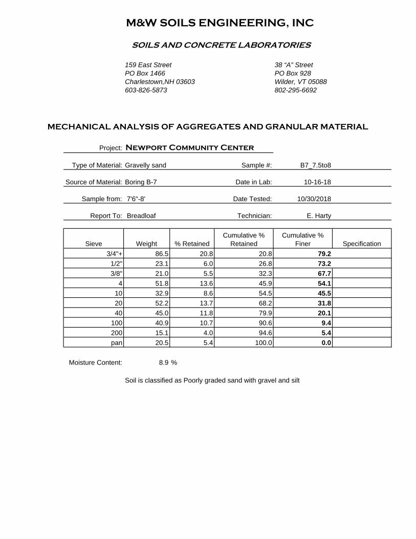
B-5 4-6’ SM, Silty sand 35.8 46.4 5B-6 4-6’ SM, Silty sand 29.9 37.2 6B-7 7.5-8’ SP-SM, Poorly
graded sand withsilt and gravel
5.4 8.9 50
B-8 4-6’ SP, Poorly gradedsand
2.4 4.0 19
The soil classifications are in general agreement with the field descriptions, although withthe differences in nomenclature described above. These sample results illustrate severalpoints made above. The layer of silty sand from 4 to 6 feet at B-5 and B-6 is consistent,but the soil profile for what I refer to as the east side of the building shows that it doesn’textend any deeper than 6 feet. These two samples reflect the soil likely to be encounteredin the footing excavation in these areas. The moisture contents reflect the ability of thesilty soils to retain much more water than the sandy soils.
Environmental Concerns
We have no knowledge of previous environmental studies or concerns on this site. Wedid identify some limited areas with soils that smelled of oil or creosote. These are not ofa concern from the geotechnical standpoint to any greater degree than other fill soils, butthey could have an impact on construction. Further investigation by the Owner would bewarranted.
Recommendations for Design and Construction:
1) This site will have an IBC Seismic Site Class of “D”, per the 2009 through 2015 IBCCode, based on average blow counts. There is a concern about liquefaction potential ofthe underlying native soils. Clean saturated sands in thick layers with relatively shallownon-liquefiable soils above them are most prone to liquefaction. Lateral spreading due toliquefaction is not likely, due to the depth to the saturated clean sands and the localtopography, potential damage would be the result of liquefaction causing sand movementfrom within the bearing zones beneath footings. This area is not prone to the magnitudeof earthquake that would cause this type of movement, and this commentary may have noeffect on the structural design.

M&W Soils Engineering, Inc. PO Box 1466, Charlestown, NH 03603 ph: 603-826-587338 A Street, Wilder, VT 05088 fax:603-826-4210
6 | P a g e
2) We have been provided with the current conceptual site plan and schematic floor planfor reference in preparing this report.
The building slab will be at a single elevation, 788.0’. The ground elevations around mostof the building are just below that elevation, there are multiple entries which requirewalks to begin at 788 at the edge of the building. It appears that the northern tip of thebuilding will integrate a retaining wall to tie into the bank at that corner. The currentground elevations are generally in the 786 to 787 range. I was assuming a bottom offooting elevation of 783.5’ for my calculations and recommendations, so the average cutto footing grade will be between 3 and 3.5’. There may need to be some lower elevationsalong the front of the building to accommodate sidewalk elevations, and at columnfootings. The profile sheets in Appendix D show the footing subgrade based on the783.5’ elevation.
As illustrated by the blow counts directly beneath the footings on either side of thebuilding, footings will bear in compact sands or silty sands in almost all locations. BoringB-7 was the only boring within the building footprint where undesirable soils were foundwithin the footing range, it is possible that other isolated areas will be encountered.
My recommendations for site preparation and foundation design are as follows:
a) Strip all organic or otherwise deleterious soils from within the building footprintand all exterior improvements (future walks, roadways, etc.). This includes currentstructures, pavement, and loam.
b) Excavate to footing subgrade. Where unsuitable soils (organics, loose orindustrial fill) are found, over excavate to undisturbed solid ground if the layer isrelatively shallow (<24”) or consult with the Geotechnical Engineer. In these overexcavated areas, use ¾” crushed stone to fill to footing subgrade. If groundwater ispresent, wrap the crushed stone with filter fabric.
Where the subgrade is firm sand, gravel, or gravelly sand, footings may be placeddirectly on the re-compacted subgrade. Final excavation shall be done with a smoothbucket or by hand digging. Use a plate compactor to recompact any disturbed areas.Where footings bear on moist silty sand or other saturated soils, over excavate and placea layer of filter fabric and a minimum of 6” of ¾” crushed stone beneath footings. TheGeotechnical Engineer should field verify all footing subgrade before crushed stone orconcrete is placed.

M&W Soils Engineering, Inc. PO Box 1466, Charlestown, NH 03603 ph: 603-826-587338 A Street, Wilder, VT 05088 fax:603-826-4210
7 | P a g e
Interior footings and column bases will likely be shallow compared to the frost protectedexterior footings, with subgrade elevations close to existing grades. In these areas,provide a minimum of 12” of compacted crushed gravel beneath concrete, extending atleast 12” beyond each face of the footing. Additional fill beneath this layer, if needed,should be Granular Backfill.
c) Backfill footings and foundation walls with Granular Backfill. Existing soilsmay be used provided they meet the backfill specification or are close enough for theGeotechnical Engineer to approve their use. There should be room on site to stockpileclean sands and gravels for mixing and compliance sampling.
d) In the interior of the building, the existing ground surface will be 1 to 1.5 feetbelow slab subgrade in most locations. Much of this area is currently gravel parkingsurface. Little would be gained by removing this soil layer and replacing it with new fill.In areas which are currently paved, buildings, or loam, this material will need to bestripped to a suitable base. Place Granular Fill to within 12” of the bottom of slab, andthen use fine crushed gravel to form the slab base.
I would recommend that an allowable bearing capacity of 3,000 psf (3 ksf) be used forfoundation design.
3) All backfill of footings and foundation walls shall consist of Granular Backfill,following the material specification provided below. Backfill shall be brought up to thelevel of the base material for concrete slabs, assumed to be crushed gravel. All backfillshall be compacted in maximum 12” thick lifts, to a minimum dry density of 95% of themaximum determined by ASTM D 1557. We would recommend that Granular Backfillbe extended at least 3 feet beyond foundation walls and around isolated column footings.
4) With no sub slab structures, a foundation drain is not necessary. Most of thefoundation will be several feet above the groundwater table, in free draining soil. A vaporbarrier is still required beneath slab on grade sections.
M&W Soils Engineering, Inc. PO Box 1466, Charlestown, NH 03603 ph: 603-826-587338 A Street, Wilder, VT 05088 fax:603-826-4210
8 | P a g e
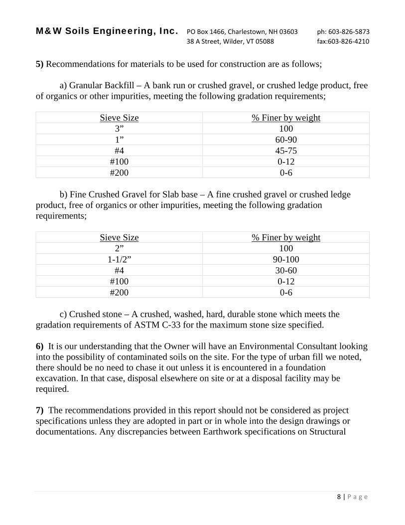
5) Recommendations for materials to be used for construction are as follows;
a) Granular Backfill – A bank run or crushed gravel, or crushed ledge product, freeof organics or other impurities, meeting the following gradation requirements;
Sieve Size % Finer by weight3” 1001” 60-90#4 45-75
#100 0-12#200 0-6
b) Fine Crushed Gravel for Slab base – A fine crushed gravel or crushed ledgeproduct, free of organics or other impurities, meeting the following gradationrequirements;
Sieve Size % Finer by weight2” 100
1-1/2” 90-100#4 30-60
#100 0-12#200 0-6
c) Crushed stone – A crushed, washed, hard, durable stone which meets thegradation requirements of ASTM C-33 for the maximum stone size specified.
6) It is our understanding that the Owner will have an Environmental Consultant lookinginto the possibility of contaminated soils on the site. For the type of urban fill we noted,there should be no need to chase it out unless it is encountered in a foundationexcavation. In that case, disposal elsewhere on site or at a disposal facility may berequired.
7) The recommendations provided in this report should not be considered as projectspecifications unless they are adopted in part or in whole into the design drawings ordocumentations. Any discrepancies between Earthwork specifications on Structural


APPENDIX A
Test Boring Locations Map
Overlain on Aerial Photo
Newport Community Center
Meadow Road, Newport, NH


APPENDIX B
Test Boring Field Logs
& Summary of Blow Counts and Boring Depths
Newport Community Center
Meadow Road, Newport, NH

M&W SOILS ENGINEERING, INCPO Box 1466 Charlestown, NH 03603 603-826-5873
TO:Breadloaf Corporation1293 Route 7 SouthMiddlebury, VT 05753
PROJECT NAME:
LOCATION:
MW JOB #:
Newport CommunityCenterMeadow RoadNewport, NH
11936-18
SHEET:DATE:HOLE #:LINE & STA.OFFSET:
1 of 110-16-2018B-1
Ground Water Observations
8’9” at Immed. hours
Augers-Size I.D. 3.25”Split Spoon 1.5"Hammer Wt. 140#Hammer Fall 30"
Surface Elevation:Date Started:Date Completed:Boring Foreman:Inspector:Soils Engineer:
10-16-201810-16-2018T & K Drilling
R.Rhoades
LOCATION OF BORING: In front of ball field sign, 4’ into gravel parking
Sample DepthsFrom/To
(Feet)
Blows per 6" onSampler
MoistureDensity orConsist.
StrataChange
Elev.
Soil Identification SampleNo. Pen. Rec.
Inches Inches0-2’ 11/6/5/4 Clean sandy gravel 1 24 18
2-4’ 4/4/4/10 12” Brown mixed sand fill 2 24 3
4-6’ 11/19/18/15 4’ Clean light brown gravelly sand 3 24 18
6-8’ 13/15/14/15Dry
6.25’
7’
Light grey to light brown sandy silt
Clean light brown medium sand
4 24 20
10-12’ 5/8/9/9 Wet 10’ Clean brown medium to coarse sand 5 24 22
15-17’ 3/4/5/6 15’ Light brown medium sand 6 24 24
25-27’ 2/2/5/6
28’
Same, some coarse sand layers
Clean coarse sand, little fine gravel
7 24 24
35-35.5’ NA
35’ Same, flowing sands rose 2’ in auger, blowcounts not reliable
8 6 24
47’ Flowing sands terminated further progress
Ground Surface to 47’ Used: HSA
Earth Boring 47’Rock CoringSamples: 8HOLE NUMBER B-1

M&W SOILS ENGINEERING, INCPO Box 1466 Charlestown, NH 03603 603-826-5873
TO:Breadloaf Corporation1293 Route 7 SouthMiddlebury, VT 05753
PROJECT NAME:
LOCATION:
MW JOB #:
Newport CommunityCenterMeadow RoadNewport, NH
11936-18
SHEET:DATE:HOLE #:LINE & STA.OFFSET:
1 of 110-16-2018B-2
Ground Water Observations
NONE
Augers-Size I.D. 3.25”Split Spoon 1.5"Hammer Wt. 140#Hammer Fall 30"
Surface Elevation:Date Started:Date Completed:Boring Foreman:Inspector:Soils Engineer:
10-16-201810-16-2018T & K Drilling
R.Rhoades
LOCATION OF BORING: Near center of front of proposed building
Sample DepthsFrom/To
(Feet)
Blows per 6" onSampler
MoistureDensity orConsist.
StrataChange
Elev.
Soil Identification SampleNo. Pen. Rec.
Inches Inches0-2’ 10/8/8/7 6”
12”
Crushed gravel
Gravelly sand fill
Light brown sand
1 24 20
2-4’ 13/17/17/18 28” Brown gravel 2 24 8
4-6’ 6/7/7/8 4.25’ Olive silt, trace clay 3 24 24
6-8’ 7/8/9/10 4 24 20
8-10’ 5/7/7/10 8’ Olive clayey silt, occasional sand lens 5 24 20
10-12’ 3/6/6/9 15’ Grey silt, little fine sand 6 24 22
15-17’ 3/3/3/3
18’ Grey to orange-brown clean medium sand, tracecoarse sand
7 24 20
20-22’ WH/7/16/25 Same 8 24 22
22’ Terminated boring
Ground Surface to 20’ Used HSA casing: Then drove SS to 22’
Earth Boring 22’Rock CoringSamples: 8HOLE NUMBER B-2

M&W SOILS ENGINEERING, INCPO Box 1466 Charlestown, NH 03603 603-826-5873
TO:Breadloaf Corporation1293 Route 7 SouthMiddlebury, VT 05753
PROJECT NAME:
LOCATION:
MW JOB #:
Newport CommunityCenterMeadow RoadNewport, NH
11936-18
SHEET:DATE:HOLE #:LINE & STA.OFFSET:
1 of 110-16-2018B-3
Ground Water Observations
3’ at 18 hours
Augers-Size I.D. 3.25”Split Spoon 1.5"Hammer Wt. 140#Hammer Fall 30"
Surface Elevation:Date Started:Date Completed:Boring Foreman:Inspector:Soils Engineer:
10-16-201810-16-2018T & K Drilling
R.Rhoades
LOCATION OF BORING: In ballfield, near proposed building corner
Sample DepthsFrom/To
(Feet)
Blows per 6" onSampler
MoistureDensity orConsist.
StrataChange
Elev.
Soil Identification SampleNo. Pen. Rec.
Inches Inches0-2’ 2/4/16/18 4”
3’
Loam
Loamy gravelly sand fill
Drilling on rock 2-3’
Native boney gravel, apparent cobbles
1 24 12
4-5’3” 6/32/50/3” Wet 5’ Same 2 15 14
6’ 25/0” 3 24 24
8-10’ 10/18/19/20 8’ Clean brown gravelly coarse sand 4 24 16
10-12’ 25/13/14/16 Same 5 24 16
15-17’ 7/17/22/35 15’
17’
Same, but very light brown
Refusal, likely boulder
Ground Surface to 15’ Used HSA casing: Then drove SS to 17’
Earth Boring 17’Rock CoringSamples: 5HOLE NUMBER B-3

M&W SOILS ENGINEERING, INCPO Box 1466 Charlestown, NH 03603 603-826-5873
TO:Breadloaf Corporation1293 Route 7 SouthMiddlebury, VT 05753
PROJECT NAME:
LOCATION:
MW JOB #:
Newport CommunityCenterMeadow RoadNewport, NH
11936-18
SHEET:DATE:HOLE #:LINE & STA.OFFSET:
1 of 110-16-2018B-4
Ground Water Observations
NONE
Augers-Size I.D. 3.25”Split Spoon 1.5"Hammer Wt. 140#Hammer Fall 30"
Surface Elevation:Date Started:Date Completed:Boring Foreman:Inspector:Soils Engineer:
10-16-201810-16-2018T & K Drilling
R.Rhoades
LOCATION OF BORING: In front of center overhead door of 15 Meadow Road
Sample DepthsFrom/To
(Feet)
Blows per 6" onSampler
MoistureDensity orConsist.
StrataChange
Elev.
Soil Identification SampleNo. Pen. Rec.
Inches Inches.5-2’ 9/10/12 2”
12”
Asphalt
Gravelly sand fill
Clean light brown medium sand, trace fine gravel
1 18 18
2-4’ 7/4/12/11 3’
3.5’
Old asphalt over native loamy sand
Clean gravel
2 24 12
4-6’ 11/20/28/30 5.5’ Clean light brown medium sand 3 24 20
6-8’ 29/33/36/35
Wet 7.5’
6’ Clean light brown gravelly medium to coarsesand
4 24 16
10-12’ 6/3/7/13 10’ Light brown medium sand 5 24 20
15-17’ 1/4/5/8
17’ Terminated boring, flowing sands
6 24 20
Ground Surface to 15’ Used HSA casing: Then drove SS to 17’
Earth Boring 17’Rock CoringSamples: 6HOLE NUMBER B-4

M&W SOILS ENGINEERING, INCPO Box 1466 Charlestown, NH 03603 603-826-5873
TO:Breadloaf Corporation1293 Route 7 SouthMiddlebury, VT 05753
PROJECT NAME:
LOCATION:
MW JOB #:
Newport CommunityCenterMeadow RoadNewport, NH
11936-18
SHEET:DATE:HOLE #:LINE & STA.OFFSET:
1 of 110-17-2018B-5
Ground Water Observations
NONE
Augers-Size I.D. 3.25”Split Spoon 1.5"Hammer Wt. 140#Hammer Fall 30"
Surface Elevation:Date Started:Date Completed:Boring Foreman:Inspector: M.G.Soils Engineer:
10-17-201810-17-2018T & K Drilling
LOCATION OF BORING: NE of Fire Department building
Sample DepthsFrom/To
(Feet)
Blows per 6" onSampler
MoistureDensity orConsist.
StrataChange
Elev.
Soil Identification SampleNo. Pen. Rec.
Inches Inches0-2 5/7/11/15 4” Dark brown medium sand
Medium brown sand to gravel
1 24 17
2-4’ 14/14/8/5 Brown gravelly medium sand 2 24 9
4-6’ 3/3/2/2 4’1” Dark brown silty sand, trace coarse sand 3 24 24
6-8’ 2/4/9/15 Wet 6’8” Brown medium sand, some gravel 4 24 16
8-10’ 15/8/6/6
11’ Medium brown sand
5 24 14
10-12’ 10/3/6/6 6 24 24
15’ Light grey to light brown medium sand, clean
20’ Flowing sands plugging augers, terminated
Ground Surface to 20’ Used HSA
Earth Boring 20’Rock CoringSamples: 6HOLE NUMBER B-5

M&W SOILS ENGINEERING, INCPO Box 1466 Charlestown, NH 03603 603-826-5873
TO:Breadloaf Corporation1293 Route 7 SouthMiddlebury, VT 05753
PROJECT NAME:
LOCATION:
MW JOB #:
Newport CommunityCenterMeadow RoadNewport, NH
11936-18
SHEET:DATE:HOLE #:LINE & STA.OFFSET:
1 of 110-17-2018B-6
Ground Water Observations
NONE
Augers-Size I.D. 3.25”Split Spoon 1.5"Hammer Wt. 140#Hammer Fall 30"
Surface Elevation:Date Started:Date Completed:Boring Foreman:Inspector:Soils Engineer:
10-17-201810-17-2018T & K DrillingM.G.
LOCATION OF BORING: 50 feet southeast of 2 car garage building
Sample DepthsFrom/To
(Feet)
Blows per 6" onSampler
MoistureDensity orConsist.
StrataChange
Elev.
Soil Identification SampleNo. Pen. Rec.
Inches Inches0-2’ 8/8/12/8 Medium brown gravel 1 24 14
2-4’ 5/2/6/8 Stone, no sample returned 2 24 1
4-6’ 6/3/3/11 Brown fine to medium gravelly silty sand 3 24 8
6-8’ 17/40/42/47
7’
Medium to coarse gray sand
Dense medium sandy gravel
4 24 16
8-10’ 38/17/10/8 9’6” Gray to light brown clay 5 24 15
10-12’ 5/5/5/7 Gray to light brown silty clay 6 24 16
12-14’ 1/1/2/3 Same 7 24 12
14-16’ 1/1/4/5 Gray to light brown fine sandy clay,silty at bottom 8 24 18
Ground Surface to 14’ Used HSA casing: Then drove SS to 16’
Earth Boring 16’Rock CoringSamples: 8HOLE NUMBER B-6

M&W SOILS ENGINEERING, INCPO Box 1466 Charlestown, NH 03603 603-826-5873
TO:Breadloaf Corporation1293 Route 7 SouthMiddlebury, VT 05753
PROJECT NAME:
LOCATION:
MW JOB #:
Newport CommunityCenterMeadow RoadNewport, NH
11936-18
SHEET:DATE:HOLE #:LINE & STA.OFFSET:
1 of 110-17-2018B-7
Ground Water Observations
None
Augers-Size I.D. 3.25”Split Spoon 1.5"Hammer Wt. 140#Hammer Fall 30"
Surface Elevation:Date Started:Date Completed:Boring Foreman:Inspector:Soils Engineer:
10-17-201810-17-2018T & K DrillingM.G.
LOCATION OF BORING: 15 feet South of 2-car garage building
Sample DepthsFrom/To
(Feet)
Blows per 6" onSampler
MoistureDensity orConsist.
StrataChange
Elev.
Soil Identification SampleNo. Pen. Rec.
Inches Inches0-2’ 9/8/5/4 3” Gravel
Brown medium sand, trace coarse sand
1 24 18
2-4’ 3/2/2/1 3’11” Dark brown silty fine sand 2 24 16
4-6’ 4/6/6/25 5’6” Black silty fine sand,minor brick and glass, odorof creosote or old oil
3 24 7
6-8’ 26/27/25/25 Wet 7.5’ Brown orange coarse sandy gravel 4 24 17
10-12’ 3/4/2/6 Gray clay and fine sand 5 24 17
15-17’ 2/2/5/5 17’ Gray clay and fine sand to brown rusty fine sand 6 24 19
20-22’ 2/4/5/5 22’ Red-brown fine sand, boring terminated at 22’ 7 24 16
Ground Surface to 20’’ Used HSA casing: Then drove SS to 22’
Earth Boring 22’Rock CoringSamples: 7HOLE NUMBER B-7

M&W SOILS ENGINEERING, INCPO Box 1466 Charlestown, NH 03603 603-826-5873
TO:Breadloaf Corporation1293 Route 7 SouthMiddlebury, VT 05753
PROJECT NAME:
LOCATION:
MW JOB #:
Newport CommunityCenterMeadow RoadNewport, NH
11936-18
SHEET:DATE:HOLE #:LINE & STA.OFFSET:
1 of 110-17-2018B-8
Ground Water Observations
NONE
Augers-Size I.D. 3.25”Split Spoon 1.5"Hammer Wt. 140#Hammer Fall 30"
Surface Elevation:Date Started:Date Completed:Boring Foreman:Inspector:Soils Engineer:
10-17-201810-17-2018T & K DrillingM.G.
LOCATION OF BORING: 150 feet southeast of Fire Dept building
Sample DepthsFrom/To
(Feet)
Blows per 6" onSampler
MoistureDensity orConsist.
StrataChange
Elev.
Soil Identification SampleNo. Pen. Rec.
Inches Inches0-2’ 17/16/13/10 8” Light gray gravelly sand
Medium brown gravelly sand
1 24 16
2-4’ 7/11/15/25 2’8” Brown orange medium sand, some gravel 2 24 13
4-6’ 8/8/11/18 Light brown to yellow medium sand, trace coarsesand
3 24 18
6-8’ 40/29/16/12 Damp Gravelly coarse sand, light brown to yellow-brown 4 24 16
10-12’ 4/4/5/7 Wet Clean, med to fine light brown sand 5 24 16
15-17’ 5/3/5/5 Clean light brown medium fine sand 6 24 15
Ground Surface to 15’ Used HAS casing: Then drove SS to 17’
Earth Boring 17’Rock CoringSamples: 6HOLE NUMBER B-8

M&W SOILS ENGINEERING, INCPO Box 1466 Charlestown, NH 03603 603-826-5873
TO:Breadloaf Corporation1293 Route 7 SouthMiddlebury, VT 05753
PROJECT NAME:
LOCATION:
MW JOB #:
Newport CommunityCenterMeadow RoadNewport, NH
11936-18
SHEET:DATE:HOLE #:LINE & STA.OFFSET:
1 of 110-17-2018B-9
Ground Water Observations
NONE
Augers-Size I.D. 3.25”Split Spoon 1.5"Hammer Wt. 140#Hammer Fall 30"
Surface Elevation:Date Started:Date Completed:Boring Foreman:Inspector:Soils Engineer:
10-17-201810-17-2018T & K DrillingM.G.
LOCATION OF BORING: Parking lot south of center field
Sample DepthsFrom/To
(Feet)
Blows per 6" onSampler
MoistureDensity orConsist.
StrataChange
Elev.
Soil Identification SampleNo. Pen. Rec.
Inches Inches0-2’ 15/20/23/23 6”
1’6”
Gray to brown gravel
Brown medium sand, trace gravel
Gravelly medium sand with clay
1 24 24
2-4’ 15/16/19/16 Very dark brown medium sand,trace coarsesand, apparent creosote odor
2 24 13
4-6’ 4/1/2/10
5’8”
Dark brown to black silty clay
Brown to yellow medium sandy gravel
3 24 18
6-8’ 22/19/33/41 Brown sandy gravel 4 24 16
8-10’ 10/11/16/29 Wet Dark gray medium sandy gravel, clean 5 24 20
Ground Surface to 8’ Used HSA casing: Then drove SS to 10’
Earth Boring 10’Rock CoringSamples: 5HOLE NUMBER B-9

Summary of Blow Counts and Boring DepthsProposed Newport Community Center
Depth B-1 B-2 B-3 B-4 B-5 B-6 B-7 B-8 B-90-1’ 17 18 6 9 12 16 17 33 351-2’ 9 15 34 22 26 20 9 23 462-3’ 8 30 11 28 7 5 18 313-4’ 14 35 23 13 14 3 40 354-5’ 30 13 38 31 5 9 10 16 55-6’ 33 15 58 4 14 31 29 126-7’ 28 15 62 6 57 53 69 417-8’ 29 19 71 24 89 50 28 748-9’ 12 28 23 55 21
9-10’ 17 39 12 18 4510-11’ 13 9 38 9 13 10 7 811-12’ 18 15 30 20 12 12 8 1212-13’ 213-14’ 514-15’ 215-16’ 7 6 24 5 9 4 816-17’ 11 6 57 13 10 1020-21’ 7 621-22’ 41 1025-26’ 426-27’ 11*
* B-1 was terminated at 47’ with no further sampling beyond 27’
Values in bold are the last sample taken on that boring.

APPENDIX C
Laboratory Gradation Reports
Newport Community Center
Meadow Road, Newport, NH

M&W SOILS ENGINEERING, INC
SOILS AND CONCRETE LABORATORIES
159 East Street 38 “A” StreetPO Box 1466 PO Box 928Charlestown,NH 03603 Wilder, VT 05088603-826-5873 802-295-6692
Project: Newport Community Center
Type of Material: Silt Sample #: B2_6to8
Source of Material: Boring B-2 Date in Lab: 10-16-18
Sample from: 6-8' Date Tested: 10/30/2018
Report To: Breadloaf Technician: N. Adams
Sieve Weight % RetainedCumulative %
RetainedCumulative %
Finer Specification3/4" 0.0 0.0 0.0 100.01/2" 0.0 0.0 0.0 100.03/8" 0.0 0.0 0.0 100.0
4 0.0 0.0 0.0 100.010 0.0 0.0 0.0 100.020 0.0 0.0 0.0 100.040 0.2 0.3 0.3 99.7
100 0.5 0.6 0.9 99.1200 0.6 0.8 1.6 98.4pan 77.8 98.4 100.0 0.0
Moisture Content: 34.1 %
Sample was washed.
MECHANICAL ANALYSIS OF AGGREGATES AND GRANULAR MATERIAL

M&W SOILS ENGINEERING, INC
SOILS AND CONCRETE LABORATORIES
159 East Street 38 “A” StreetPO Box 1466 PO Box 928Charlestown,NH 03603 Wilder, VT 05088603-826-5873 802-295-6692
Project: Newport Community Center
Type of Material: Gravelly sand Sample #: B3_4to6
Source of Material: Boring B-3 Date in Lab: 10-16-18
Sample from: 4-5'3" Date Tested: 10/30/2018
Report To: Breadloaf Technician: E. Harty
Sieve Weight % RetainedCumulative %
RetainedCumulative %
Finer Specification3/4" 18.4 5.5 5.5 94.51/2" 61.6 20.1 25.6 74.43/8" 13.2 4.3 29.9 70.1
4 35.1 11.4 41.3 58.710 27.8 9.1 50.4 49.620 35.4 11.5 61.9 38.140 38.2 12.5 74.4 25.6
100 37.0 12.1 86.5 13.5200 17.9 5.8 92.3 7.7pan 23.5 7.7 100.0 0.0
Moisture Content: 9.5 %
Soil classifies as Poorly graded sand with gravel and silt
MECHANICAL ANALYSIS OF AGGREGATES AND GRANULAR MATERIAL

M&W SOILS ENGINEERING, INC
SOILS AND CONCRETE LABORATORIES
159 East Street 38 “A” StreetPO Box 1466 PO Box 928Charlestown,NH 03603 Wilder, VT 05088603-826-5873 802-295-6692
Project: Newport Community Center
Type of Material: Gravelly sand Sample #: B4_6to8
Source of Material: Boring B-4 Date in Lab: 10-16-18
Sample from: 6-8' Date Tested: 10/30/2018
Report To: Breadloaf Technician: E. Harty
Sieve Weight % RetainedCumulative %
RetainedCumulative %
Finer Specification3/4" 11.2 3.1 3.1 96.91/2" 30.2 9.0 12.1 87.93/8" 22.7 6.8 18.9 81.1
4 36.7 11.0 29.9 70.110 20.8 6.2 36.1 63.920 46.0 13.8 49.9 50.140 58.0 17.4 67.2 32.8
100 54.7 16.4 83.6 16.4200 28.1 8.4 92.0 8.0pan 26.6 8.0 100.0 0.0
Moisture Content: 9.0 %
Soil is borderline Poorly graded or Well graded sand with gravel and silt
MECHANICAL ANALYSIS OF AGGREGATES AND GRANULAR MATERIAL

M&W SOILS ENGINEERING, INC
SOILS AND CONCRETE LABORATORIES
159 East Street 38 “A” StreetPO Box 1466 PO Box 928Charlestown,NH 03603 Wilder, VT 05088603-826-5873 802-295-6692
Project: Newport Community Center
Type of Material: Silty sand, trace gravel Sample #: B5_4to6
Source of Material: Boring B-5 Date in Lab: 10-16-18
Sample from: 4-6' Date Tested: 10/30/2018
Report To: Breadloaf Technician: N. Adams
Sieve Weight % RetainedCumulative %
RetainedCumulative %
Finer Specification3/4" 0.0 0.0 0.0 100.01/2" 0.0 0.0 0.0 100.03/8" 3.0 2.7 2.7 97.3
4 10.6 9.4 12.1 87.910 4.9 4.4 16.5 83.520 12.3 11.0 27.4 72.640 12.8 11.4 38.8 61.2
100 15.9 14.2 53.0 47.0200 12.6 11.2 64.2 35.8pan 40.2 35.8 100.0 0.0
Moisture Content: 46.4 %
Sample was washed.
MECHANICAL ANALYSIS OF AGGREGATES AND GRANULAR MATERIAL

M&W SOILS ENGINEERING, INC
SOILS AND CONCRETE LABORATORIES
159 East Street 38 “A” StreetPO Box 1466 PO Box 928Charlestown,NH 03603 Wilder, VT 05088603-826-5873 802-295-6692
Project: Newport Community Center
Type of Material: Silty sand, trace gravel Sample #: B6_4to6
Source of Material: Boring B-6 Date in Lab: 10-17-18
Sample from: 4-6' Date Tested: 10/30/2018
Report To: Breadloaf Technician: N. Adams
Sieve Weight % RetainedCumulative %
RetainedCumulative %
Finer Specification3/4" 0.0 0.0 0.0 100.01/2" 5.0 4.2 4.2 95.83/8" 5.6 4.7 8.9 91.1
4 2.4 2.0 10.9 89.110 8.0 6.7 17.6 82.420 11.9 10.0 27.5 72.540 16.2 13.6 41.1 58.9
100 22.9 19.2 60.3 39.7200 11.8 9.9 70.1 29.9pan 35.7 29.9 100.0 0.0
Moisture Content: 37.2 %
Sample was washed.
MECHANICAL ANALYSIS OF AGGREGATES AND GRANULAR MATERIAL
M&W SOILS ENGINEERING, INC
SOILS AND CONCRETE LABORATORIES
159 East Street 38 “A” StreetPO Box 1466 PO Box 928Charlestown,NH 03603 Wilder, VT 05088603-826-5873 802-295-6692
Project: Newport Community Center
Type of Material: Gravelly sand Sample #: B7_7.5to8
Source of Material: Boring B-7 Date in Lab: 10-16-18
Sample from: 7'6"-8' Date Tested: 10/30/2018
Report To: Breadloaf Technician: E. Harty
Sieve Weight % RetainedCumulative %
RetainedCumulative %
Finer Specification3/4"+ 86.5 20.8 20.8 79.2
1/2" 23.1 6.0 26.8 73.23/8" 21.0 5.5 32.3 67.7
4 51.8 13.6 45.9 54.110 32.9 8.6 54.5 45.520 52.2 13.7 68.2 31.840 45.0 11.8 79.9 20.1
100 40.9 10.7 90.6 9.4200 15.1 4.0 94.6 5.4pan 20.5 5.4 100.0 0.0
Moisture Content: 8.9 %
Soil is classified as Poorly graded sand with gravel and silt
MECHANICAL ANALYSIS OF AGGREGATES AND GRANULAR MATERIAL

M&W SOILS ENGINEERING, INC
SOILS AND CONCRETE LABORATORIES
159 East Street 38 “A” StreetPO Box 1466 PO Box 928Charlestown,NH 03603 Wilder, VT 05088603-826-5873 802-295-6692
Project: Newport Community Center
Type of Material: Clean sand Sample #: B8_4to6
Source of Material: Boring B-8 Date in Lab: 10-17-18
Sample from: 4-6' Date Tested: 10/30/2018
Report To: Breadloaf Technician: E. Harty
Sieve Weight % RetainedCumulative %
RetainedCumulative %
Finer Specification3/4"+ 0.0 0.0 0.0 100.0
1/2" 0.0 0.0 0.0 100.03/8" 2.6 0.8 0.8 99.2
4 24.0 7.8 8.7 91.310 31.5 10.3 18.9 81.120 73.9 24.0 43.0 57.040 100.9 32.8 75.8 24.2
100 58.9 19.2 95.0 5.0200 8.1 2.6 97.6 2.4pan 7.3 2.4 100.0 0.0
Moisture Content: 4.0 %
Soil is classified as Poorly graded sand with gravel and silt
MECHANICAL ANALYSIS OF AGGREGATES AND GRANULAR MATERIAL
APPENDIX D
Soil Profiles based on Boring Logs
Newport Community Center
Meadow Road, Newport, NH

