for starting and stoppihg the pumps - … c laboratory report no. i 50 i cont!huation of studies to...
TRANSCRIPT

HYDRAULICS BRANCH OFFICIAL FILE COPY
* * * * * * * * * * * * * * * * * * * * * * * * * * * * * * * * * * * * * * * * * * * * * * * * * * * * * * * * * * *
UNITED STATES DEPARTMENT OF THE INTERIOR
BUREAU OF RECLAMATION
HYDRAULi C LABORATORY REPORT NO. i 50 I
CONT!HUATION Of STUDIES TO DETERMINE SUITABLE METHOD FOR STARTING AND STOPPING THE PUMPS
AT GRANBY DAM PUMPING PLANT
COLORADO-BIG THOMPSON PROJECT, COLORAuO
by
J. N, BRADLEY, ENGINEER
Denver, Colorado, Sept. 20, 1944
* * * * *
* * * * * * * * * * * * * * * * * * * *
* * * * * * * * * * * * * * * * * * * * * * * * * * * * * * * * *
.'A

•
•
UNITED STATES
DEPARTMENT OF THE INTERIOR
BUREAU OF RECLAMATION
HYDRAULIC LABORATORY REPORT NO. 150
SUBJECT: CONTINUATION Of STUDIES TO DETERMINE SUITi,BLE METHOD
FOR STARTING AND STOPPIHG THE PUMPS
AT GRANBY DAM PUMPII\G PU.1-'.'f
COLOR1�DO BIG THOMPSON PROJECT, COLOPJtDO
By J. N. BRADLEY, ENGINEER
Under Direction of
J. E. WARNOCK, SENIOR ENGINEER
and
R. F. BLANKS, SENIOR ENGINEER
Denver, Colorado, Sept. 20, 1944.

..
•
UNITED STATES DEPARTMENT OF THE INTERIOR
BUREAU OF RECLAMATION
Branch of Design and Construction Engineering and Geological Control and Research Division
Denver, Colorado September 20, 1944
Laboratory Report No. 150 (Supplements laboratory
Report No. 113) Hydraulic laboratory Compiled by: J. N. Bradley Reviewed by: J. E. Warnock
Subject: Continuation of studies to determine suitable method for starting and stopping the pumps at Granby Drun pumping plant - Colorado-Big Thompson project, Colorado.
1. Purpose of investigation. The tests described in this report
constitute a continuation of those previously described in hydraulic
laboratory report 113, 11 Studies to determine suitable methods for
starting and stopping the pumps at the Granby pumping plant," by J. N.
Bradley, Fred I.ocher, w. A. Morgan, and T. F. Hammett, June 15, 1942 •
As the pumping plant and the problems involved have been described in
the above report, these will be treated briefly here.
The plant ultimately will house four pumps, of approximately 6,000
horsepower each, which will be subject to discontinuous operation re
quiring frequent starting and stopping. The starting or the stopping
of pumps of this size under full load would cause dimming of lights and
interference with the operation of automatic equipment throughout the
vicinity, as the rate of power input to the pump motors would, in some
cases, exceed the rate of response of the generators at Green Mountain
Dam. The tests described both here and in the previous report were per
formed in an effort to alleviate this condition.
The purpose of the tests described herein was to study the feasi
bility of starting the pumps while throttling the flow in the intake
lines. The main objective in this case was to eliminate the purchase
of valves for the discharge lines. The information desired is best
stated in a memorandum to the Chief Electrical and Mechanical Encineer
by Mr. I. A. Winter, 11 Proposed laboratory study of startine; the Gr9.nby

•
pumps while throttling flow in the suotion pipes - Granby Pumping
Plant - Colorado-Big Thompson Project," dated May 2, 1944. Investiga
tion of the following points was requesteda
(a) Surg1ng,1n the discharge line when the inflow is
leu than the normal capaoi ty of the pump under heads rang
ing from the minimum to the maximum.
(b) Observation of the tendency of the pump to oavi
tate excessively during the starting oyole.
(o) Observation of the behavior of the water entering
the suction tube of the pumps at high velocities.
The initial pump house valve layout is shown on.figure 1, HYD-113.
For the valve and the pipe layout used in this second series of
studies, shown on figure l of this report, the discharge valve origi
nal� used was eliminated and two intake valves were provided instead
of one. One valve was to be used for throttling and the other was to
provide for emergency closure. It was proposed to start a pump with
one intake valve closed and the discharge line full of water. With the
pump up to speed, the intake valve would be opened at a constant rate
until full load was imposed on the pump. The procedure was to be re
versed when stopping the pump.
2. The test equipment. Arrangement of the test equipment for
these studies wa.s essentially the same as for the initial investiga
tion, as is evident from a comparison of figures 6 and 7, HYD-113,
and figure 2 of this report. The same 8-inch vertical pump was used
in both oases. In the former tests a tank reservoir was employed to
supply water to the pump, while in the latter tests a booster pump was
connected in series with the intake line, ma.king p�ototype pressures
possible. The model approximated a general scale of 117 (table 1, HYD-
113) except for the discharge line. The confining walls of the labora
tory restricted the height of the discharge pipe to one-third of its
scaled value and the length to only a fraction of the scaled distance
2

--...
l <t. �_to. 2.1+ $Q.�
� --�--- __ -- - - - •
� 0 '";.c
1�·-0·· .;:>4 ·
I :
- -------·- -- • •
,
----•-·--- g', --- _ _ . . ---- - - �
,- El g.3 G &, r
· Ii ; __ ·-'<P -r· -- -----·-- '· Pumprno P! +- ___ ---.i:'. __ . ___ .'0 __ 2._ ·
- ' P.- ..., I · · · 1 . -- - , on � -- -- 1
� £ -"" I \ ,·r ·
---,-- ,� ·-- · · · ' 00 ::l . • . . • ' j - . ./ / �1· - -- - -- ---- . : "- -,, ' • • • • •
• ' ,. , ../ •• ,
• ' • I
c:. t o 1 • , . • --r�- . · . ; ·.. ,
-,, --· . - ' J_ _ . . I· .. > . . . . . ' '
a . 2' -1---· ---l II .
. _- ,
1' l ' q_Max [L_i2�QO(Ji • -· ' ' -·(,[\,3290.00 l1 1l1
I
I
I
Supp-ressor 2.45 f P.>F .Zll
g'
;;;wJtY' - E�---'----t---- _-,- . '-:f �--·-----,--. Line continue$! :l
a
I
/
I
, , I n+ak.e
c-•··:e'··-�\\
2. 3
Gppf"Ol'-. Z1oOO ft. � , r \_ ·ro" I. D. steel pipe
- - I 1.D.Tunrie! ;a !
·Q -= 2.00 to 3-50 c.f s. I
;;;;-�---� 2.5 H, 27 _____ __,_ _______ ��-7. i 29
Valve. to be throttled/,
GRANBY P-UA
M Pl NG PLANT
SECTION TH.RU _INTAKE. UNE. 1 PUMP HOUSE AND
DISCHARGE. . LINE.. "TJ Q C ;o r1

MODEL TEST LAYOUT FOR GRANBY DAM PUMPING PLANT
t\'.l

to be traversed by the prototype conduit.
Instrumentation consisted of a voltmeter. an ammeter, and a watt
meter connected as shown in figure 13, HYD-113, between a single phase
and the ground. Three electric, strain-gage type, pressure cells
(P. C. 4, P. C. 5, and P. C. 6) were located as shown on figure 2 of this
report for recording pressure changes in the intake. the pump suction
tube, and the discharge line. In addition to the above instruments,
electric tachometers were provided to measure the speed of the motor
and the rate of opening of the intake valve. Instantaneous records of
the pressure cells, the motor speed, the valve position, and the elec
tric current were recorded by the laboratory oscillograph. An attempt
was ma.de to record the voltage, but, due to the fact that the oscillo
graph contained no shielded channels, the 60-cycle frequency was super
imposed on the record of every channel. After discovering that _the
voltage fluctuation amounted to no more than 5 percent, this measure
ment was not considered important. A record of the power required by
the motor was also desired, but a watt element was not available for
the oscillograph. The primary interest in this study concerned surges
in power rather than actual values, and thes e are clearly manifest in
the current trace on the oscillograms. It should be kept in mind, how
ever, that the general shape of the power record would vary considerably
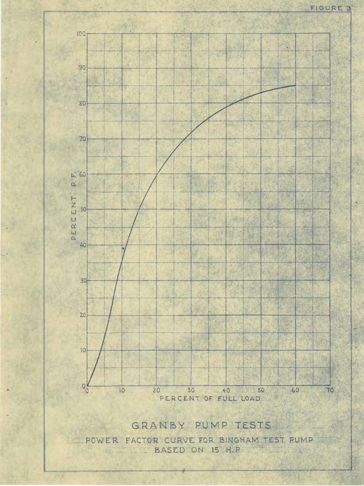
from the current trace •. Although the voltage remained relatively con
stant, the power factor du.ring these tests varied from zero to 85 per
cent, as can be observed from figure 3. This curve shows the power
factor plotted with respect to the rated capacity of the motor for the
actual range over which it operated during these tests. In no case
did the motor on the test pump operate at greater than half of its rated
capacity.
The pressure cells were a type used for the first time in the lab
oratory, and they will therefore be described here as a matter of rec
ord. A cell (figure 4) consisted of two steel arms, one stationary and
the other movable. The movable arm was rigidly connected to a diaphragm
5
. .
• ' .
I
')
I ·.· J-�···
. L.'. 'f,QJ--....,.'-'--!-'+-+---,:--r---¥--,-,-�+---,---+----t-'=-+---,-,.:--,....t---'--...,......,....,.....
0.:
tz 501-+--i--�+-------,l---+---+----,-l--'---+---+--_c...;....:..,-i-:--:--t----'--+--......,-,;�� Lu u � t..J .. Cl,,
. I :A�
,. I
.... -.... �--{-,-.........c.,.--- --�---·-·
_____ i .... ____,_
·10 20 30
PE.RC£-NT OF
ON 15 l

..
3" Zs 0. D. Cap----
f Pipe tap--'-
I I
',_ /" 0. D. tube 3/g" long
1 '--Gasket '--2B!eeders(#4-40) ASSEMBLY - SIDE VIEW
STRAIN METER UNIT - TOP VIEW SHOWING WIRING OF EXPANSION COIL
STRAIN METER UNIT - BOTTOM VIEW SHOWING WIRING OF CONTRACT/ON COIL
NOTES
FIGURE 4
Sealinq chamber filled with GE. No.227 insulafinq compound Sf rain meter unif filled with casfor oil leuvinq Zc.c. air space. Pressure chamber filled w/fh wafer before embedmenf. Sfrain mefer unit same as in Carlson stress mefer.
LABORATORY ELECTRIC HYDROSTATIC
PRESSURE GAGE

which flexed as pressure changes were applied to its opposite side.
Two coils of wire, one consisting of four loops and the other of five
loops, were strung over porcelain insulators mounted between the steel
arms. The ooils were strung to oppose one another in such manner that
a movement of the diaphragm would increase the tension on one and re
duce the tension on the other. Movement of the diaphragm in the oppo
site direction would reverse the strain, making the instrument adapt
able for the measurement of intermittent, positive, and negative pres
sures. Piano wire, 0. 0025 inch in diameter, possessing a fairly high
strain sensitivity, gave most satisfactory results of a number of wires
investigated. The dual coil served to equalize the variation of resis
tance produced in the two wires by temperature changes. Upon final
assembly, to limit temperature change the coils were encased in oil.
The output of these cells was sufficient to make possible the elimina
tion of vacuum-tube amplifiers at the input to the oscillograph.
3. Test procedure. Referring to figure 2, the first test was
performed with the 2-inch bypass valve open, the 8-inch discharge valve
open, the 8-inch intake valve closed, and both lines filled with water.
The booster pump on the intake line was started, thus producing a defi··
nite prototype pressure on the upstream side of the intake valve. Then
the test pump was started, ai'ter which the 8-inch intake valve was
opened at a steady rate. With this valve �ully open, the 2-inch bypass
valve was closed, completing the starting cycle. The stopping cycle
constituted the same procedure in reverse.
It was desired to investigate this procedure of operation, both
with and without aeration. Air could be supplied to the suction tube
of the pump through the 2-inch vent, shown on figure 2. This would
correspond to approximately a 14-inch vent in the prototype. A pipe
of the same size (figure 2) served as a bypass between the suction and
the discharge lines of the pump. The purpose of the bypass in these
tests was to provide circulation for cooling while the intuke valve
was closed.
8

•
Three variables were involved in this method of o�eration: (1)
the static pressure on the intake line, which varied from 10 to 120
feet in the prototype, (2) the rate of opening and closing of the in
take valvea and (3) the area of the air vent. As stated previously,
the discharge line was not to soalea however, the results showed this
factor to be unimportant in this case. Testing was performed over
the complete range of the three variables. In compiling the results
it was found that two tests sufficed to show that throttling of the
flow in the intake line was not a desirable method of operation.
4. Starting and stopping oyoles with air vent open. The oscil
logram on figure 5 shows the conditions in the starting and the stop
ping cycle with the 2-inoh air vent (figure 2) open to the atmosphere.
With the test pump at rest, the pressure on the intake line (P. C. 4,
figure 2) was 83 feet of water, the suction-tube pressure (P.c. 5) was
10.5 feet, and the pressure on the discharge line (P.c. 6) was 9.5
feet. The starting of the test pump is indicated by the current trace
on figure 5 and also by the motor tachometer which registered each_
revolution of the pump. The frequency of the osoillograph galvanom
eters was not sufficient, upon starting of the motor, to produce an
accurate traoe of the current from the standpoint of amplitude.
Approximately one seeond after the test pump was started (figure
5), a positive pressure surge amounting to 32 feet of water occurred
in the discharge line, which was likewise reflected in the current
trace, the latter registering a surge of 36 to 23 amperes. Although
negative in sign, a corresponding pressure surge of 12 feat of water
was recorded in the suction tube of the pump. The seoond surge, the
peak of which oocurred at a valve opening of about 14 percent, regis
tered a positive pressure of 26 feet in both the suction tube and the
discharge line. As the intake valve was opened at a uniform rate,
repetition of the surging occurred in the discharge line and the suc
tion tube of the pump until the intake valve reaohed approximately 40
percent open. For valve openings of 40 to 100 percent the pressures
9

FIGURE 5
� "' I.
i,t ,- Intake Line PC.4
•.• -Discharge Line P.C.6
C: <I)
_,__,,__ , � .-Motor Tachometer ·-�-12 .... , ..
73'
,-P. C.4 25'
-- P.C.6
ii I 1d11-111)IH• ""ii . .-J...-
rirt' ('l"l"/if\r 1 /"NV"f'f'll'V'\ty'(" .fil'ff'v'/i1v'l/ifV\l"f\lVY'V'.fifV\1'l/i/il"i'V'V"'/ifV\1"fV'\rY'"l'VVi/if'l/'·l"l"r f' � 11 l"f' /" /" /" l"r/" I" 1 rl/' r rf'l"f'f'1rf'rr/"/"f'rrr/"f'f'/"f'
I\ ln;okeVolve Position lndicctor··, ( . i \ f\.r V V I V \_ "-r- � ,,---. v-._f' �.
i5 l�
�---------5.2 --- • :,. 10 _ 15 20
INTAKE VALVE OPENING IN PERCENT STARTING CYCLE
,111\l1il i\111 l 1li j1 Ll 11 ld/nl 1 \ 111 1 \111 1li 11 ill 11 1 1ll11 .iLi11\111 l1\ n1d1 11 1\1,1 .\111 111111d 1 1 1\111.1Pd ,i 1 1 , ,i1 1 1 ,\1 1 1 I\ 11.,( 1 1 d 11l,L11L\ 1i11\l1ildl 1 i1\11d,1 1o1,L1 l,\,1d111111,lli 11\1u 1L1,l,l11, ,ll111iL.i1,L111 1ll11 1ni1, 1 111 1 , LI 1 11 1 1L.....__i.1 • 1 11, d. 1 d, ,,L
1e' ___ ?C.6
I IJ 1�1 i I Ill I .j 11
P.C.4 .!.,'
� l'l'l"f"I" r I l"rf\r r l"l'rrl"' r r 11 l"r rl" rv'l"l"l"·r 1r'r'firrr I" rf' f'v I" f"f"'l""l'l"r /" /"1-I" /"f"'r IV"' /irl" /"/"I"/" l"f' /" l"l"v l"f'l"r, /"l"rl"'r f' f' I"' r r v r f"'r r r r r r r,, r r r, r, �,�V--\.,_/"' I vr v--�,.rrv·· v v "'),,----Y------v----\r I \.,r r-"' r-"'/j "'-� � � r
35 40 4 5 50 55 60 65 .. ,
- -P.C.6 ·9'
I • I 11· • j ' I� I I I I J I f I I I I 11 HIii io11 1,1 1 11Jldl1'11dld.1 1l
INTAKE VALVE OPENING IN PERCENT STARTING CYCLE
I .. I I I . I I I I . I 1 dl 1 1i l 11 ,.�,L .. ,1 il,1,••1,11\ 1 l 1 !1 t •• .. \ 1i ,' 1i �11 11• I l11111lill1 1 I II 1 ii1h,.\l1 ,11 l 1 1ii 1l111l11111i11d11,l111. i 1_ili 11,1 1 l 1i 1i 1 11 i .i\l 1 , 111 1 id1d11ll�l1ddjj,IIJlll1i\l11111 1!11! 111 IIIIIIHl 1 i1 ldl ,,tl,11 1111
-------------------->
_Q_4 -
P.C.4-
Ii. li11 Ill 11_11; i1 ,:.� I ,,11, 1 11 •
,, I I Ir' r" r" /" r' I I I Iv' r r'r r' I Irr r' l""r\f'\r I IV"' r /"' /""/1f'\/"r1f"' r' If"' I f'f'rV .r' f"' I"" f'\r /"'"'r I' I I' f"f"'r I r'v' r·f'\/"'•r r' f'I r' f"/""' I I r'r'fit I'( I I f'V"' f"' f'\r Ir ff I Ir I Ir
"'-1 -- --- ,,... I\" v--v--v--1 \,�'�'v\.ir V V I V \"-r--'v-----y---,.r \"-,,-- ·I
45 40 3 5 3 0 2 5 2.0
\ � v \·
50
�---------- INTAKE VALVE OPENING IN PERCENT STOPPING CYCLE
82' .-P.C.4 :nroke Line
... 0 ... 0
.-?.C.6 o·schorgeLine
1��������/""�r���������l"'��N�-�C�r.rnn, , ,, �V--·v 1,,r' l \,,-V \I"" 0 \. r I \ . r! I \ r ' . \ '0�:"lr_.-.ii;.f�I 1111111•�-i--1 �r-..... ,-. _...,.... _ _._ ___ � '\.· · I ' > I\..., '- '--� 'Int-eke \/olvelFt>sition Ind1ca1or
15 10 5 O
( Ir-' r-: -
INTAKE VALVE OPENING IN PERCENT STOPPING CYCLE
GRANBY PUMP TESTS
OSC ILLOGRAMS OF STARTING AND STOP PING C YCLES WITH SUCTION TUBE VENTED AND BY-PASS OPEN
T H RO TTL ING ACCO MP LI S HE D WI TH INT A KE VALVE

at the three cells became quite steady with little change in magnitude.
For this reason, the oscillographic records have not been reproduced
for the complete starting and stopping cycles. The lower portion of
figure 5 shows the record of the pressures and the current for the
stopping cycle. In this case the operating procedure was the opposite
of the starting cycle. The pressure surges for this case were not as
severe as for the starting cycleJ however, distinct surges in the cur
rent occurred throughout both cycles. For the valve partially open,
surging was audible in the model as air was intennittently pulled
through the air vent pipe. In no case was the flow through the vent
steady.
As a means of demonstrating that the rate of opening or closing
of the intake valve had little bearing on the pressure fluctuations,
a short oscillogre..m was made with the intake valve held at a critical
operating point. This is shown as the lower record on figure 6, which
indicates pressure surges in the discharge line of 25 to 5.5 feet of
water, with corresponding current surges of 40 to 25 amperes. Each
surge was accompanied by an audible intake of air through the vent pipe.
The condition shown on figure 6 persisted, with little variation for
valve openings of 5 to 30 percent.
With pressure-surge indications such as these manifest in a model
havinE a discharge line much undersealed, it is certain that pressure
changes in the prototype would be more severe than those indicated by
the model. As the pressure changes are accompanied by corresponding
fluctuations in the power required by the motor, the above plan for
starting and stopping the Granby pumps is not considered feasible.
5. Starting and stopping cycles without aeration. The oscillo
gram on figure 7 is a record of the instantaneous pressures and the
current obtained for operation similar to that above-described except
that the valve in the air-supply vent was closed. With the pump at
rest, the pressure in the intake line (P. C. 4) was 82 feet of water,
the pressure in the discharge line (P. C. 6) was 9.5 feet, and the
11

Intp k e ]L i ne ] P.c,-. - ,
O S C I LL O G R A M O B TA I N E D AT C R I T I C A L O P E R A T I N G P O I N T - 1 4 P E R C E N T V A L V E O P E N I N G
S U C T I O N T U B E N OT V E N T E D - B Y - PA S S O P E N
O S C I L L O G R A M O B T A I N E D FO R C R I T I C A L O P E R A T I N G Z O N E - 5 TO 3 0 P E R C E N T V A L V E O P E N I N G
S U C T I O N T U B E V E N T E D - B Y- P A S S O P E N
G R A N B Y P U M P T E S T S
T H R O T T L I N G A C C O M P L I S H E D W I T H I N T A K E V A L V E
"Tl
G)
C
::0
ITI
en

1 1 I l r ' l l 1
1,
�-------
3 5
- tr.tok e L i n e P.C. 4
I N T A K E V A L V E S T A R T I N G
I I I
,. Di scharge Line F'.C. 6
F I G U R E 7
_#· - ;;.c.6 17
, - -P,C .4
' -?. C.5
1/YV"'�����l\l'VVVVVVVYVVV''�IV''IVVV'\IV\
�r----·,.r-rv�-�1',\f/4 I
1 \r I Y�'rt/�r-r�r 20 , _ 25 • 30
16'
I N P E R C E N T C Y C L E
;!l I N T A K E V A LV E O P E N I N G I N P E R C E N T
S T O P P I N G C Y C L E
G R A N B Y P U M P T E S T S
-------'1
S T A R T I N G A N D S T O P P I N G C Y C L E S W I T H O U T A E R A T I O N - B Y - P A S S O P E N
T H R O TT L I N G A C C O M P L I S H E D W I T H I N T A K E V A L V E

pressure in the suction tube of the pump (P. C . 5) was 10 feet. Upon
starting of the motor, the pressure in the sucti on tube dropped to a
negative 22 feet of water, while the pressure in the discharge line
fluctuated from 3 to 28 feet. A corresponding positive surge was re
flected in the suction tube of the pump. As the intake valve was un
seated; a ioud crackling noise occurred which persisted, although de
creasing in intensity, unti l the valve was about 20 percent open. The
crackling noise was cavitation produced by the high-veloci ty jet shoot
ing along the invert of the suction tube. For the smaller valve open
ings, water was supplied to the test pump at a deficient rate, thus
produci ng an initial negative pressure in the sucti on tube . In addi
tion, the high-velocity jet issuing from under the gate leaf tended to
skip over the invert of the suction tube because of gate-slot interfer
ence and imperfecti ons in the surface downstream, producing localized
negative pressures. The addi tive effect of these two actions caused
the pressure along the suction- tube invert to be reduced to the vapor
pressure of water, thus developing oondi-tions conducive to cavitation
although P. C. 5, located on the side of the suction tub e, did not indi
cate pressures this low. As the intake valve continue d to open, the
static i ntake head dropped to 15 feet of positive pressure at 50 percent
valve opening, the pressure in the pump suction tube reversed to
slightly positive, and the pressure in the discharge li ne increased
approxi mately 7 feet over the original pressure in overcoming fricti on
caused by flow in the line. The oscillogram reproduced on figure 7 was
out at a valve opening of 50 percent , as pressure fluctuations beyond
this point were insignificant.
The pressure record for the stopping cycle is shown in the lower
portion of figure 7. As the valve opening reached 10 percent, the
pressure in the pump suction tube fell to a negative 28 feet, or the
vapor pressure of water at this altitude. The low pressure was accom
panied by a crackling noise which is indicative of the presence of
cavitati on. In addition to the crackling noise , the fluid passing
14

•
through the pump wae a mixture of air and water, the air being released
from the water by vaporiz ation. This air, as demonstrated in the pre
ceding s ection, would be very undesirable in the prototype . Following
complete closure of the intake valve, a series of surges occurred in
both the dis eharge line and the auction tube of the pump, but little
fluctuation was evidenced in the current trace . Upon disengag�nent of
the pump motor fro m the power sour ce, water hammer developed in the
discharge line and the suction tube. This also would be undesirable in
the prototype when one considers that extremely long lines are involved.
Figure 7 i s interesting in that the current i s steady throughout both
oyoles in s pite of the pressure conditions .
A short osci llogram was made of the most critical operating point
for thi s condition of operation, which appeared to be at a valve open
ing of approximately 14 percent. Although the suction-tube pressure
was negative 24 feet of water, the pressures in general were steady,
whi ch demonstrates that in this case the rate of opening and closing of
the intake valve would not material ly affect the pressures o-f figure 7.
Nevertheless, this type of operation i s not recommended for the Granby
pumps.
To remedy the above operating disadvantages, i t is suggested that
the throttling be accomplished by a valve placed in each dis charge line
as proposed originally . It is felt that these valves will more than
pay for themselves in reduced maintenance costs and fewer operational
difficulties, to say nothing of the advantages to be gained in the re
duction of power and pressure surges during the starting and the stop
ping cycles.
6. Throttling with discharge valve. Since the osoi llograms shown
in HYD- 113 were ma.de, the laboratory oscillographic equipment has been
greatly improved. For thi s reason the test shown on figure 18 A and B
of that report was repeated. In that test the pump was brought up to
speed with auxi liary water jets, whi le in the present tests the pump
was started electri cal ly, with the impeller rotating in air . Referring
15

to the photograph on figure 2 and the oscillogra.m on figure 8 of this
report - with the 8-inch discharge valve closed, the bypass valve open,
and the intake valve open, compressed air was fo rced into the suction
tube of the pump, thus unwatering the pump impeller . The test pump
was then started in air, electrically, at which point the oscillographic
record on figure 8 begins. The entrapped air then was expelled steadily
through a small valve on the discharge side of the pump, causing gradual
submergence of the impeller . The timing of this procedure is recorded
on figure 8. Upon completion of the air removal, the sudden rise in all
three pressure curves indicates the po int at which the test pump became
fully primed. The stopping cycle, shown in the lower part o f the figure,
was the reverse of the starting cycle, and, in this case, the pressures
for both cycles were similar. The stopping cycle consisted of closing
the di scharge valve at a constant rate. Upon complete closure, com
pressed air was forced into the suction tube of the pump, unwatering the
rotating impeller at a steady rate. When fully unwatered,· the motor on
the test pump was deenergized. Pressure fluctuations can be controlled
to a large extent, in this case, by decreasing the rate of opening and
closing of the discharge valve and decreasing the rate of intake and ex
pulsion of compressed air to the pump chamber. In the case of the model
pump, the operation was carried out at a moderate speed in order that
the reco rd wo uld not be to o long and cumbersome to reproduce. There is
no lower limit to the speed of this proces s in the prototype.
In addition to stabilization o f pressures, this metho d of operation
has the outstanding advantage o f requiring less power when starting and
stopping. Figure 8 shows that it required 20 amperes to turn the pump
impeller in air against 30 amperes to do the same thing in water ( fig
ures 5 and 7) . Starting the impeller in air should therefore reduce
the initial power demand by perhaps one-third. However, no conclusions
can be drawn from the instantaneous current trace at the beginning of
each test, as the frequency o f the galvanometer elements was insufficient
to reco rd correctly the larger amplitudes.
16

I 1 1111 111i,1:i,1 1 I I !' I I I I I 1 · 1 I I I
I : :' :'· : ! I : : I : ! 01",j,,.:, , ,:. ,: , :, : : :, . . j::'f .'P :: -·: : : '': : ··� : : .. : : : : �= : : I I I I I :;
' I
F 1 G J F- � 8
=-= === -
Air E x liausl ing from Pum_e. \ia l u't e
1'0
S T A R T I N G C Y C L E
S T A R T I N G C Y C L E
D I S C H A R G E VA L V E O PE N I N G I N P E R C E N T S T O P P I N G C Y C L E
G R A N B Y P U M P T E S T S
S T A R T I N G A N D S T O P P I N G C Y C L E S W I T H P U M P I M P E L L E R R U N N I N G I N A I R - B Y- PA S S O P E N
T H R O T T L I N G A C C O M P L I S H E D W I T H D I S C H A R G E VA L V E
r r+-v,r-- ,r--,iv--
-,\ 15 2D
D I S C H A R G E V A L V E O P E N I N G I N PERC E N T
S T O P P I N G
----------;,.j

•
"
7. The bypas s valve. Although this subject was discus sed in HYD-
113, it will be mentioned again fo r emphasis. The bypas s is an es sen
tial factor for smooth operation in the s tarting and the stopping cycles.
During the starting cycle the bypass makes pos sible circu lation for
cooling. During the stopping cycle it serves as a drain for water
trapped on the discharge side of the pump and as a regu lator for con
tro l ling the rate of unwatering of the impel ler. Without the bypas s it
is not pos sible to relieve entirely the pressure developed on the dis
charge side of the pump, which, if not relieved, wi ll reflect in surges
and an increase in the pow.er requirement to the motor previous to dis
engagement.
Provision of an 8-inch pipe with gate valve should be co nserva
tively adequate for the bypas s in the prototype. The valve can be set
to unwater the impel ler at the desir ed rate on the shut-down cycle.
Upon determination of this point, a stop or limit switch can be in
stal led on the bypas s valve to limit its travel . It wi 11 be neces sary
to determine in the field the maximum valve setting, together with the
compr es sed-air pres sure and the rate at which air should be admitted to
the suction tube of the pump.
B . Summary and conclusion s . From an hydraulic standpoint , throt
tling with the intake valve is fundamental ly unsound in that extremely
low pres sures are created unneces sarily . In high head design this is
to be avo ided wherever pos sible, for past exp erience has shown the re
sults to be either unsatis factory or unpredictable. The application of
venting to relieve the condition, unneces sarily created by low pres
sures, merely complicates the problem in this ease, as a mixtu re of air
and water is an unstable fluid and pres sures throughout such a fluid
wil l be found as unstable as the fluid itself. In the case of the Granby
pumps, whe re surges in pres sure are directly affected by the power re
quirements of the motors, neither cavitation nor venting should be tol
erated, as both produc e an unstable fluid.
In conclusion, the fo l lowing recommendations are suggested in
17

.,
..
•
in connection wi th the starting and the stopping of the Granby pump s =
( a) Throttling of dis charge through the Granby pumps
by use of valves on the intake lines is inadvisab le .
{b) The most satisfactory method , to date. constitutes
$tarting and stopping the pump impellers in air and thr�t
tUng the flow with dis charge valves, as di1 eus sed in sec
tion 6 .
( c ) Instal lation o.f the bypas s ShQUld not b e over
looked when a valve is used in the diecharge line , as it pro
vide s a means of coo ling the water by eiroulation duriIJg the
period that the discharge valve i s closed and the impeller is
turni� in wa't;•r . Also , it wi:11 se"e to 00ntro l the rate at
which the power deorease s d.uri� the stopping cycle .
( d) The compressed-air intake po rt functi ons best when
located midW$Y in the aucti on t.ube of the pump. The air
exhaust port should be located on the dis charge side of the
pump, preferably in a small dome on top of the pipe where
water wi ll not interfere with the escaping air •
18