for raspberry pi® - getting started - farnell · pdf filefor raspberry pi® - getting...
TRANSCRIPT

For Raspberry Pi® - Getting startedConnect to the real world in minutes, with the most popular interface board for Raspberry Pi®.
PiFace™ Digital 2
For step by step help and ideas for projects visit: http://www.piface.org.uk/guides/
This guide applies to PiFace™ Digital 2 which is used with the Raspberry Pi® models A+ and B+ (40 pin connector).
PiFace™ Digital 2 is one of the quickest and easiest way to connect your Raspberry Pi® to the real world. Follow this guide and your Raspberry Pi® will be reacting to switches and controlling motors and lights in less than ten minutes!
The original PiFace™ Digital interface board fits the original Raspberry Pi® models A and B. PiFace™ Digital 2 has been redesigned to fit the Raspberry Pi® models A+ and B+.
Product highlights
Typical applications:● Education● Home/Industrial automation● Security monitoring● Internet of Things gateway● Remote monitoring● Hobbyist projects and games● I/O expander● User interface for systems
Features:● 2 changeover relays● 4 switches● 8 digital inputs● 8 open-collector outputs● 8 LED indicators● Easy to program in Python, Scratch and C● Graphical emulator
Technical specifications:● Changeover relays, 20V 5A switching max● 1.5mm screw terminal hole size● Operating Temp -40° to 85°
Fitting instructions
Warnings● Ensure that no power is supplied to Raspberry Pi®, or PiFace™ Digital 2 boards
when plugging or unplugging.
PiFace™ Digital 2 sits neatly above the Raspberry Pi® and connects using the expansion connector. Take care to ensure all expansion pins are lined up with the holes on the PiFace™ Digital 2 socket. Check the alignment for left and right, and front and back before pushing down and never force the boards together if they don’t slide smoothly.
Tour of hardware
PiFace™ Digital 2
Hardware features
Input ports
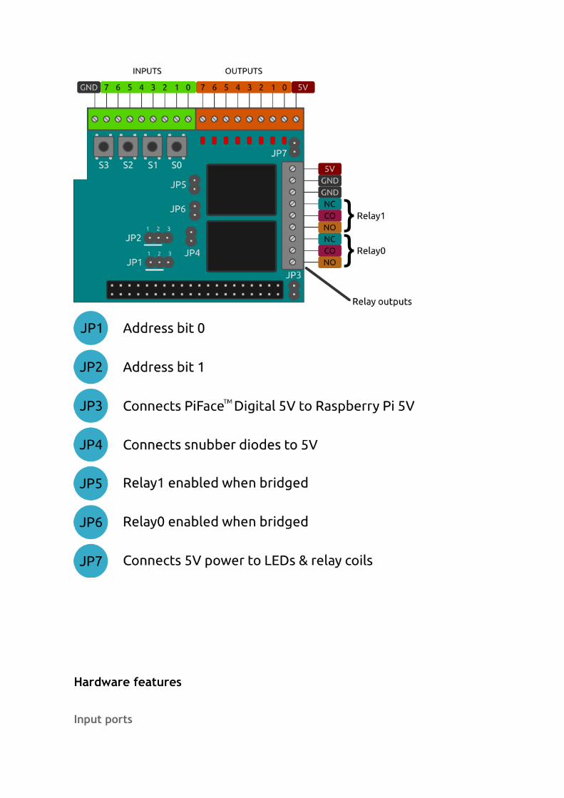
The 8 green screw terminals are inputs and used to detect if a switch or contact is open or closed. An input will register when it is connected to GND. The inputs are labelled on the underside of the board.
The four switches, labelled S0 to S3, are connected in parallel to the first four (0-3) inputs.
Example connection of a buttonTo wire up an external button connect the input pin of PiFace™ Digital 2 to one contact on the button and another wire from GND on PiFace™ Digital 2 to the other switch contact. Check your button’s datasheet to see which pins should be wired up.
Output portsThe 8 orange screw terminals are open-collector (see below for more details) outputs used to control external components such as LEDs, lights or motors and are labelled on the underside of the board.
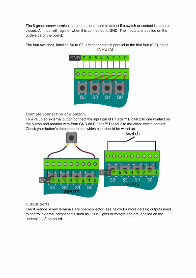
LED indicationThe onboard LEDs can be used to show the status of an application running on the Raspberry Pi® without any additional components. They are also useful for debugging circuits and code to confirm intended output state.
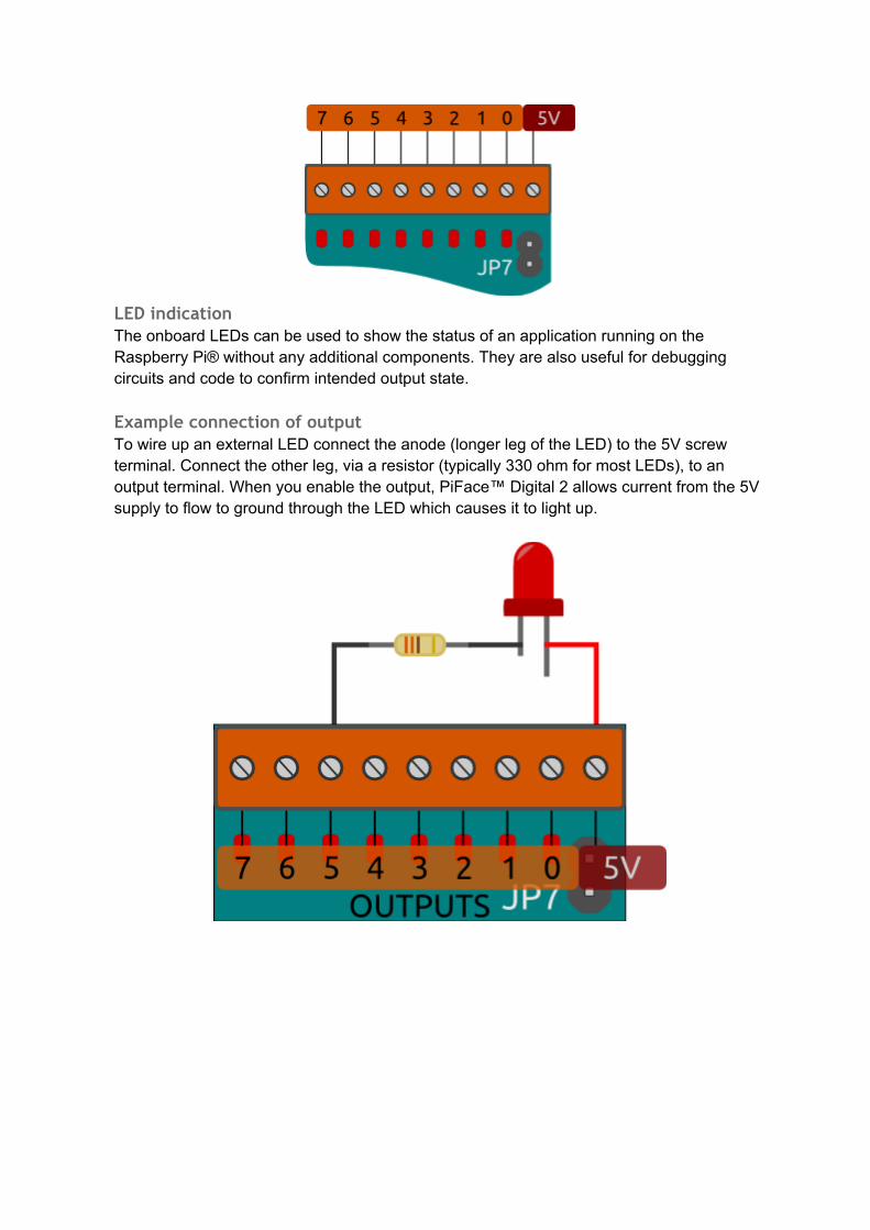
Example connection of outputTo wire up an external LED connect the anode (longer leg of the LED) to the 5V screw terminal. Connect the other leg, via a resistor (typically 330 ohm for most LEDs), to an output terminal. When you enable the output, PiFace™ Digital 2 allows current from the 5V supply to flow to ground through the LED which causes it to light up.
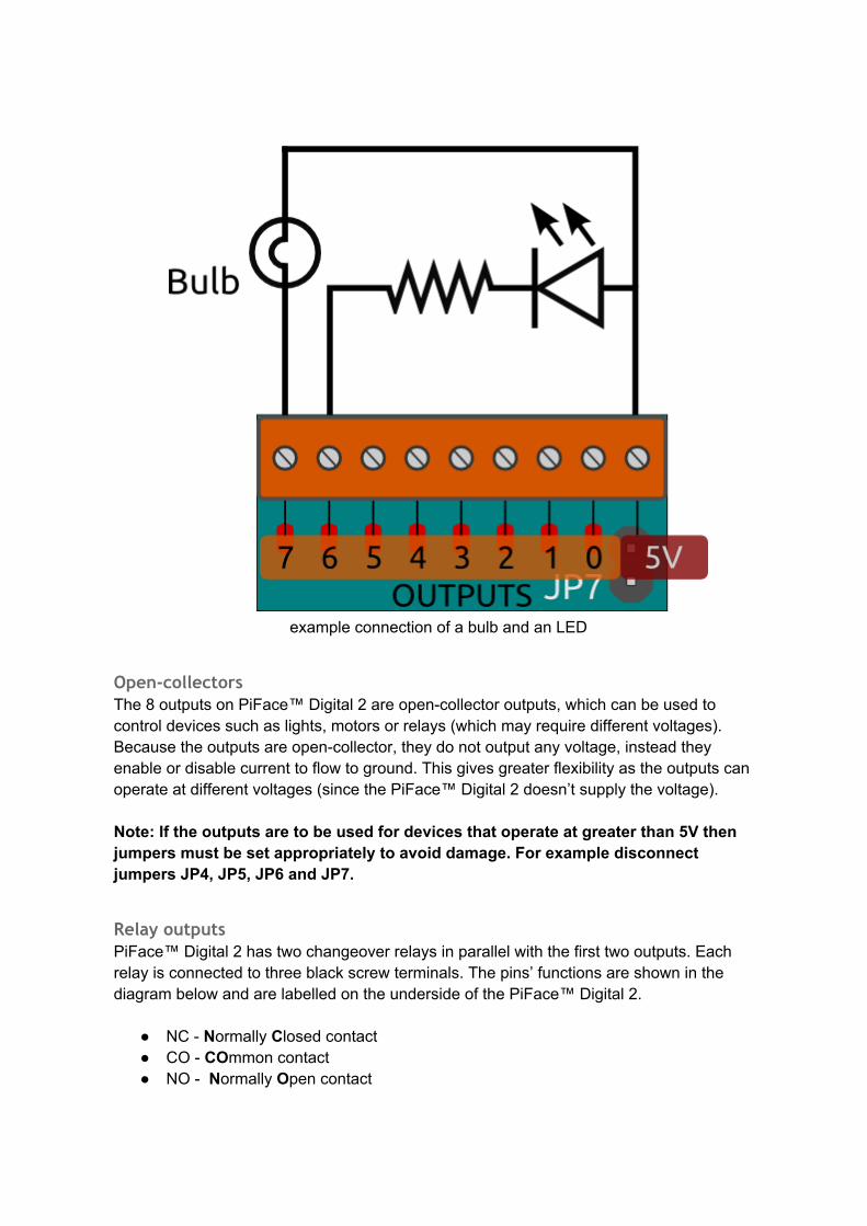
example connection of a bulb and an LED
Open-collectorsThe 8 outputs on PiFace™ Digital 2 are open-collector outputs, which can be used to control devices such as lights, motors or relays (which may require different voltages). Because the outputs are open-collector, they do not output any voltage, instead they enable or disable current to flow to ground. This gives greater flexibility as the outputs can operate at different voltages (since the PiFace™ Digital 2 doesn’t supply the voltage).
Note: If the outputs are to be used for devices that operate at greater than 5V then jumpers must be set appropriately to avoid damage. For example disconnect jumpers JP4, JP5, JP6 and JP7.
Relay outputsPiFace™ Digital 2 has two changeover relays in parallel with the first two outputs. Each relay is connected to three black screw terminals. The pins’ functions are shown in the diagram below and are labelled on the underside of the PiFace™ Digital 2.
● NC - Normally Closed contact● CO - COmmon contact● NO - Normally Open contact
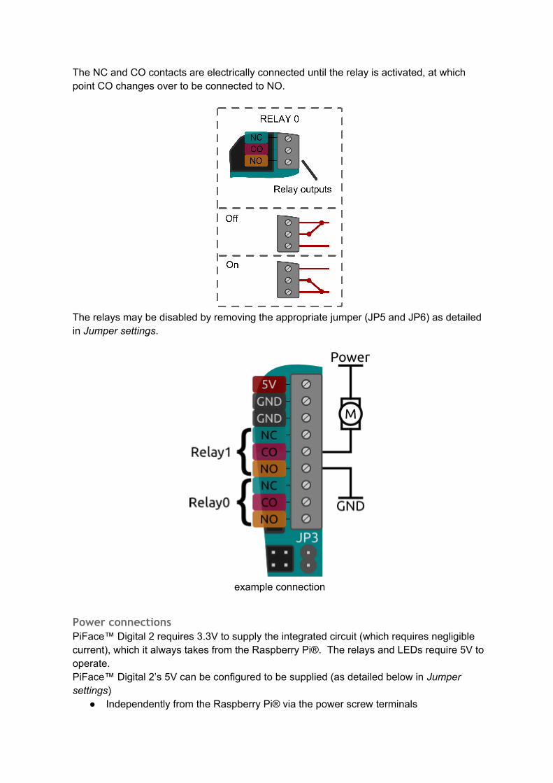
The NC and CO contacts are electrically connected until the relay is activated, at which point CO changes over to be connected to NO.
The relays may be disabled by removing the appropriate jumper (JP5 and JP6) as detailed in Jumper settings.
example connection
Power connectionsPiFace™ Digital 2 requires 3.3V to supply the integrated circuit (which requires negligible current), which it always takes from the Raspberry Pi®. The relays and LEDs require 5V to operate.PiFace™ Digital 2’s 5V can be configured to be supplied (as detailed below in Jumper settings)
● Independently from the Raspberry Pi® via the power screw terminals
● From the Raspberry Pi®’s 5V● Via the power screw terminals, and used to power the Raspberry Pi®
Warning: Never have separate power supplies for both the Raspberry Pi® and PiFace™ Digital 2, when the power jumper is connected.
Note: As discussed in the Output ports section PiFace™ Digital 2 does not supply power on its open-collector output pins or relay contacts!
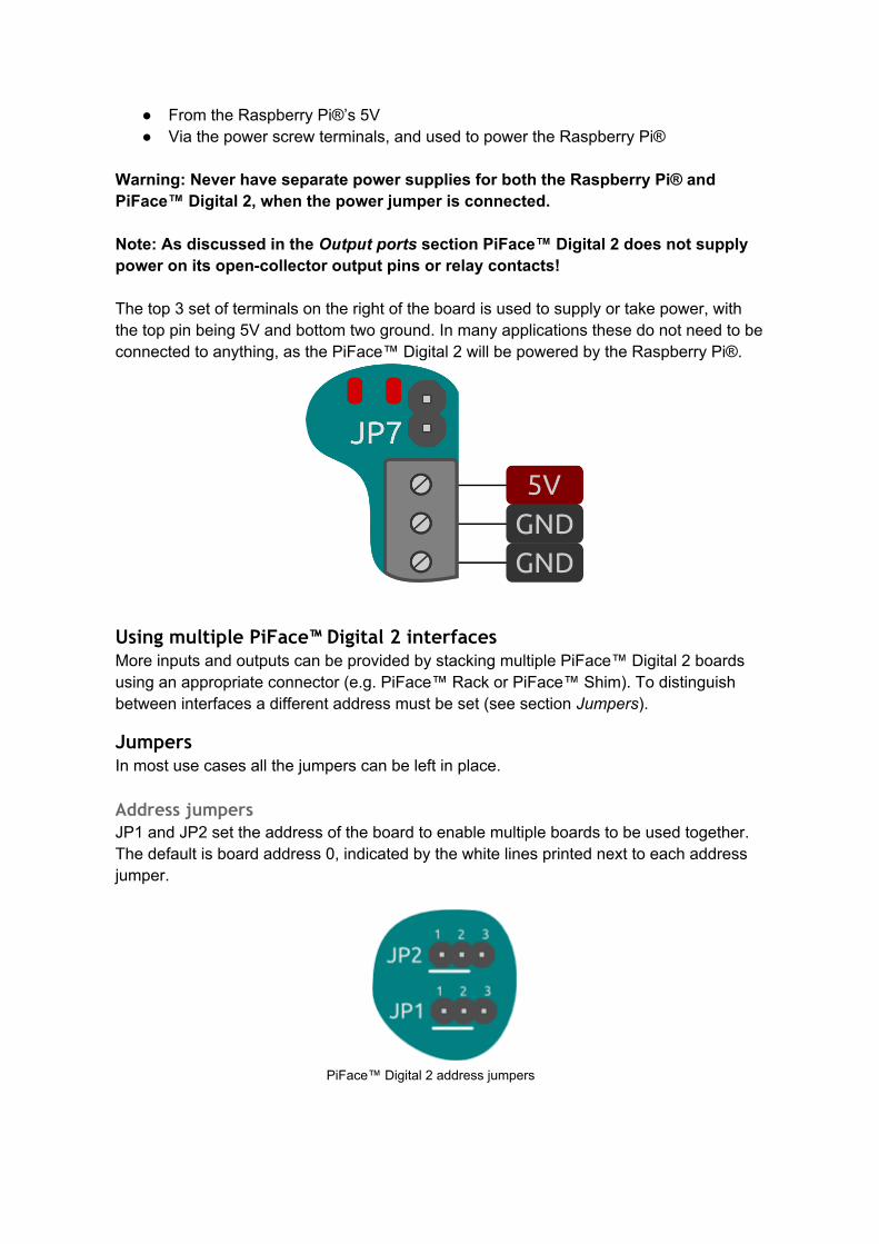
The top 3 set of terminals on the right of the board is used to supply or take power, with the top pin being 5V and bottom two ground. In many applications these do not need to be connected to anything, as the PiFace™ Digital 2 will be powered by the Raspberry Pi®.
Using multiple PiFace™ Digital 2 interfacesMore inputs and outputs can be provided by stacking multiple PiFace™ Digital 2 boards using an appropriate connector (e.g. PiFace™ Rack or PiFace™ Shim). To distinguish between interfaces a different address must be set (see section Jumpers).
JumpersIn most use cases all the jumpers can be left in place.
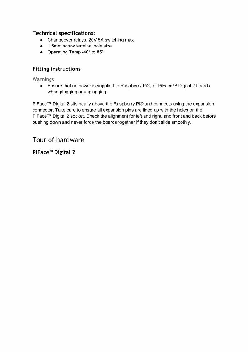
Address jumpersJP1 and JP2 set the address of the board to enable multiple boards to be used together. The default is board address 0, indicated by the white lines printed next to each address jumper.
PiFace™ Digital 2 address jumpers

Address Binary Address JP2 position JP1 position
0 00 1-2 1-2
1 01 1-2 2-3
2 10 2-3 1-2
3 11 2-3 2-3
JP1 controls the least significant bit of the address, and JP2 the most significant bit.
Power share jumperJP3 selects whether the PiFace™ Digital 2 shares the same power source as the Raspberry Pi®. This supply can be either provided through the Raspberry Pi®’s MicroUSB connector, or from an external supply provided through PiFace™ Digital 2’s 5V and GND power screw terminals. With the jumper connected, the Raspberry Pi® and PiFace™ Digital 2 will share a single power supply. Disconnected, they will each need to be powered separately.
Warning: Never use separate power supplies for both the Raspberry Pi® and PiFace™ Digital 2, when this jumper is connected.
Snubber diodes jumperJP4 connects the snubber diodes from the ULN2803A to 5V (snubber diodes protect the driving transistors from the high voltages that occur when a coil, e.g. a relay, turns off). However, if the open-collectors are connected to a supply greater than 5V, these diodes must be disconnected by removing JP4 (else the diodes will conduct between the outputs and 5V).
Relay jumpersRemove JP5 and JP6 to disconnect the relay 0 and relay 1 (respectively). This is useful if you just want to use only the open-collector or LED outputs and stop the clicking noise created by the relays when switching outputs 0 and 1.
Power jumper
JP7 connects the power to all onboard outputs (i.e. the relays and leds). Disconnect this jumper to disable the onboard LEDs and relays.
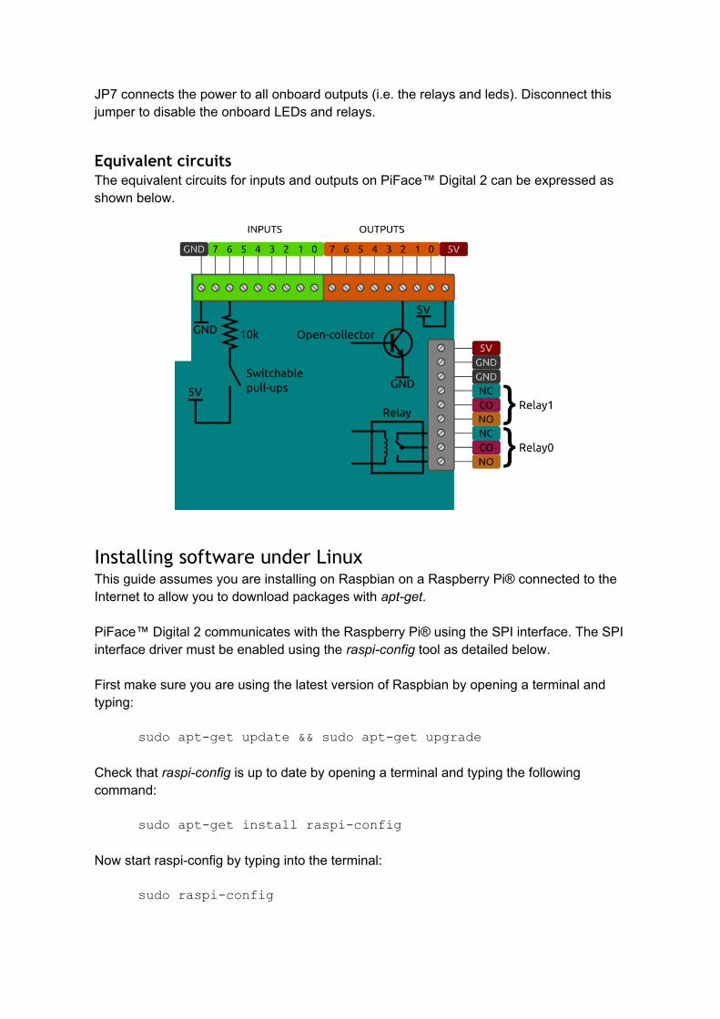
Equivalent circuitsThe equivalent circuits for inputs and outputs on PiFace™ Digital 2 can be expressed as shown below.
Installing software under LinuxThis guide assumes you are installing on Raspbian on a Raspberry Pi® connected to the Internet to allow you to download packages with apt-get.
PiFace™ Digital 2 communicates with the Raspberry Pi® using the SPI interface. The SPI interface driver must be enabled using the raspi-config tool as detailed below.
First make sure you are using the latest version of Raspbian by opening a terminal and typing:
sudo apt-get update && sudo apt-get upgrade
Check that raspi-config is up to date by opening a terminal and typing the following command:
sudo apt-get install raspi-config
Now start raspi-config by typing into the terminal:
sudo raspi-config
Use the arrow and enter keys to select Advanced Options and then select SPI, set this to <Yes> then select <OK> then <Finish>.
To install the PiFace™ Digital 2 software, open a terminal and run the following command:
sudo apt-get install python3-pifacedigitalio
To install the PiFace™ Digital 2 Emulator software, open a terminal and run the following command:
sudo apt-get install python3-pifacedigital-emulator
If you want to use Scratch with your PiFace™ Digital 2, you will need to install the PiFace™ Digital 2 Scratch handler by running this command in a terminal:
sudo apt-get install python3-pifacedigital-scratch-handler
Now reboot your Raspberry Pi®, e.g. type into a terminal:
sudo reboot
TestingAfter installing the software and restarting, login and type startx to launch the desktop environment.
Start the PiFace™ Digital emulator by typing in a terminal:
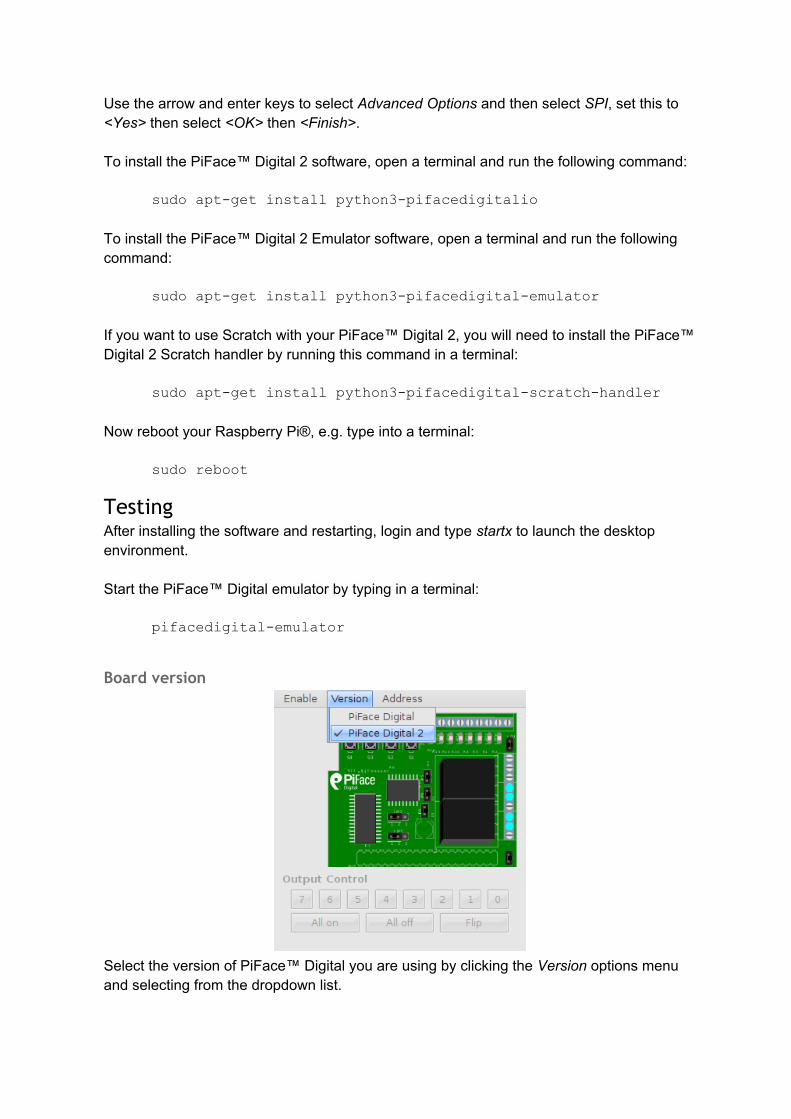
pifacedigital-emulator
Board version
Select the version of PiFace™ Digital you are using by clicking the Version options menu and selecting from the dropdown list.
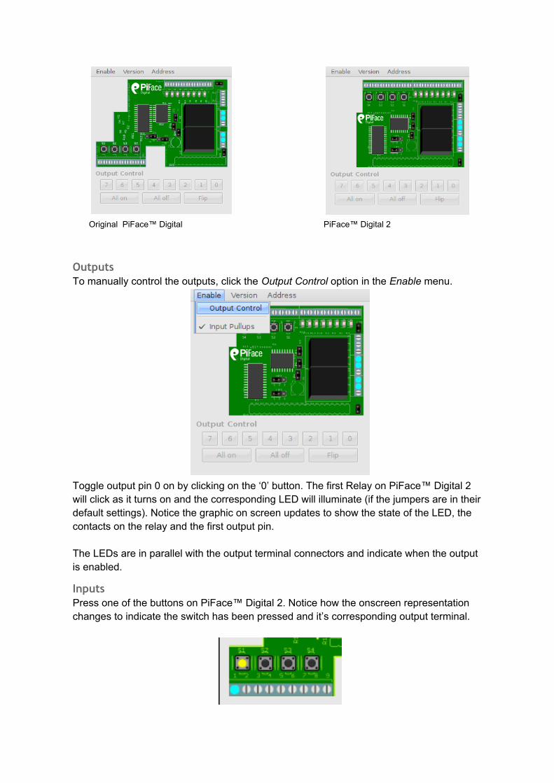
Original PiFace™ Digital PiFace™ Digital 2
OutputsTo manually control the outputs, click the Output Control option in the Enable menu.
Toggle output pin 0 on by clicking on the ‘0’ button. The first Relay on PiFace™ Digital 2 will click as it turns on and the corresponding LED will illuminate (if the jumpers are in their default settings). Notice the graphic on screen updates to show the state of the LED, the contacts on the relay and the first output pin.
The LEDs are in parallel with the output terminal connectors and indicate when the output is enabled.
InputsPress one of the buttons on PiFace™ Digital 2. Notice how the onscreen representation changes to indicate the switch has been pressed and it’s corresponding output terminal.
First steps with PythonPiFace™ Digital 2 can be controlled easily using Python. First open a terminal window and start the Python interpreter by typing:
python3
To use PiFace™ Digital 2 from Python you must import the pifacedigitalio module:
import pifacedigitalio
Before use, the board must be initialised with a call to:
pifacedigitalio.init()
Use the digital_read function to see if a button is pressed or not:
pifacedigitalio.digital_read(pin_number)
This function returns 1 if the input numbered pin_number is connected to ground or else 0.
Set the output numbered pin_number to state 0 or 1. State 1 turns the LED on and enables to open-collector to sink current.
pifacedigitalio.digital_write(pin_number, state)
Next steps with PythonA more powerful and expressive way of controlling PiFace™ Digital 2 is using the PiFaceDigital object. This will give you access to all PiFace™ Digital 2’s the features (including pull-ups and input/output ports). Start the Python interpreter with:
python3
Then instantiate the PiFaceDigital object like this:
import pifacedigitalio
pfd = pifacedigitalio.PiFaceDigital()
OutputsSet the first output pin to 1 (the on state):
pfd.output_pins[0].value = 1
Notice how the first relay clicks as it activates. Output pin 0 controls the first relay. You can turn the output pin (and the relay) off by setting it to 0:

pfd.output_pins[0].value = 0
InputsYou can read the value of an input pin like this:
pfd.input_pins[1].value
Try running the above command with the second switch pressed and then again with it un-pressed and you should get different results.
Port input/outputYou can read the whole input port by reading the value of the input_port attribute:
pfd.input_port.value
Or set the outputs for the whole port by setting the value of the output_port attribute:
pfd.output_port.value = 0xAA
Simple Python example programs
Controlling an output (turn a relay on)The relays on PiFace™ Digital 2 are connected to the first two outputs, so they can be controlled using the digital_write function.
Start a new Python interpreter and type the following:import piface.pfio as pfio
pfio.init()
pfio.digital_write(0,1)
Flashing an LEDA program to flash an LED must repeatedly turn an output on, wait for a period and then turn it off again. It is shown below:
from time import sleep
import piface.pfio as pfio
pfio.init()
while(True):
pfio.digital_write(0,1) #turn on
sleep(1)
pfio.digital_write(0,0) #turn off
sleep(1)
Reading an input
To read the state of an input use the pfio.digital_read(pin) function. If a button is pressed the function returns a 1, otherwise it returns a 0.
Start a new Python interpreter and type the following:import piface.pfio as pfio
pfio.init()
pfio.digital_read(0)
Python prints 0.Hold down the first switch, labelled S0, and type
pfio.digital_read(0) again.Python prints 1.
Touch sensitive inputsWant to use something more than switches and wires for your inputs? You can turn PiFace™ Digital 2’s inputs into touch sensitive inputs that can turn anything that conducts electricity, like bananas or people, into a switch, similar to how MakeyMakey™ works.
To use touch sensitive inputs, you need to configure PiFace™ Digital 2 so it can sense the tiny amount of electricity that flows through these objects.
For each input you want to use, connect a 25-40M ohm resistor between the input pin and 5V.
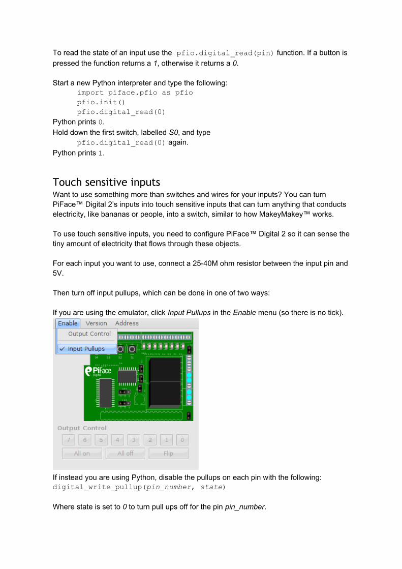
Then turn off input pullups, which can be done in one of two ways:
If you are using the emulator, click Input Pullups in the Enable menu (so there is no tick).
If instead you are using Python, disable the pullups on each pin with the following:digital_write_pullup(pin_number, state)
Where state is set to 0 to turn pull ups off for the pin pin_number.

Connect a wire to each touch sensitive input, then connect a single wire to GND on the PiFace™ Digital 2.
While holding the wire connected to GND, touch the wire connected to the input with another part of your body. When you are in contact with both wires, you complete the circuit, which the PiFace™ Digital 2 can detect, (as shown in the emulator or by performing a digital_read using Python). Try connecting one touch input wire to a piece of fruit. Now, when you hold the GND wire and touch the banana you complete the circuit.
Warnings● PiFace™ Digital 2 boards are not intended for use in critical systems. ● Do not expose to water, moisture or extremes of temperature (below -40°C or
above 85°C).● Take care whilst handling to avoid mechanical and electrical damage to the device
and connectors.● Take suitable precautions to minimise risk of causing damage by electrostatic
discharge.● Connection to unapproved devices may affect compliance or result in damage to
unit and invalidate any warranty.● Connections to PiFace™ Digital 2, including connecting external circuits or other
add-on boards, should only be made with the power supply disconnected.● Ensure that any circuits attached to PiFace™ Digital 2 are powered by a suitably
rated power supply that complies with the relevant regulations and standards applicable to the country of intended use.
Compliance information● This PiFace™ board complies with the relevant provision of the RoHS Directive
for the European Union. In common with all Electronic and Electrical Equipment this PiFace™ board should not be disposed of in household waste. Alternative arrangements may apply in other jurisdictions.
● PiFace™ Digital 2 PCB is CE marked. It is a class B product. The EMC emission test was performed with a PiFace™ Digital 2 on a Raspberry Pi® Model B and a PiFace™ Digital 2 on a Raspberry Pi® Model B+. Due to the nature of the board, as a prototyping and development board, fast transient immunity tests and conducted radio-frequency immunity tests have not been executed. ESD handling precautions should be observed. The board may be considered a component if integrated into another product. Any person designing or developing a product that uses one or more PiFace™ Digital 2 boards or any other PiFace™ products is responsible for ensuring that it is compliant and any modification to a PiFace™ board or inter-connection of other elements and devices with a board does not change compliance.
● This Class B digital apparatus complies with CAN ICES-3 (B). Cet appareil numérique de la classe B est conforme à la norme NMB-003 du Canada.
● This device complies with part 15 of the FCC Rules. Operation is subject to the following two conditions: (1) This device may not cause harmful interference, and

(2) this device must accept any interference received, including interference that may cause undesired operation.
http://www.piface.org.uk
PiFace™ is designed in the UK by OpenLX SP Ltd. Registered Office 145-157 St John Street, London, EC1V 4PW. PiFace™ is distributed by Premier Farnell UK, 150 Armley Road, Leeds LS12 2QQ, UK
Manufactured in the UK.
Documentation Revision 2.1 January 2015
Raspberry Pi is a Trademark of the Raspberry Pi Foundation. All other Trademarks acknowledged.