for of - nasa · and design of dynamic models for analysis of structural ... tory loads are...
TRANSCRIPT

4
PRINCIPLES AND PRACTICES FOR SIMULATION O F
STRUCTURAL DYNAMICS OF SPACE VEHICLES
bY
George W. Brooks
NASA - Langley Research Center
ABSTRACT
The paper discusses the philosophy and p r inc ip l e s for t he se l ec t ion
and design of dynamic models for analysis of s t r u c t u r a l dynamics of space
vehicles.
of modeling t o launch vehicles and spacecraf t , and considerations r e l a t i v e
t o damping and model support systems. An appendix is included which sum-
marizes t h e various dimensionless r a t i o s used i n aerospace f l i g h t .
Subjects t r e a t e d include s imil i tude, model s ca l ing , appl icat ions
INTRODUCTION
From p r a c t i c a l considerations w e begin with the s i t u a t i o n t h a t w e have a
s t ruc tu re which is designed t o glace some usefhl payload i n t o space. Typical
examples include both clustered and nonclustered configurations with e i t h e r
https://ntrs.nasa.gov/search.jsp?R=19690009647 2018-07-27T10:04:12+00:00Z

-xvII -2-
l iquid- or solid-propellant systems. During the performance of t h i s t a sk ,
t he structure is subjected t o an environment or combination of environments,
which induces ex te rna l and/or i n t e r n a l responses of t h e s t ruc tu re .
ample, wind loads create ex te rna l motions of these s t ruc tu res and induce
For ex-
i n t e r n a l stresses i n the s t r u c t u r a l elements. A s engineers we have both
a professional i n t e r e s t and r e spons ib i l i t y , pecu l i a r t o our own f i e l d of
endeavor, t o maximize the eff ic iency and r e l i a b i l i t y of t h e s t ruc tu res which
we employ. Although o w pr inc ipa l i n t e r e s t a t t h i s conference and t h e con-
t e n t of t h i s paper are p r inc ipa l ly devoted t o space vehicle systems, t he
reader w i l l recognize t h a t t h e general philosophy and much of t he basic
content a r e generally appl icable t o s t ruc tu res associated with other
engineering d i sc ip l ines .
I n order t o design e f f i c i e n t space vehicle s t ruc tu res we must have
adequate means f o r predict ing the cha rac t e r i s t i c s of t h e s t ruc tu re , t he
environment and loads t o which it i s subjected, and i t s response. I f t h e
s t ruc tu res were simple and t h e environment and loads wel l defined i n a
s p a t i a l and temporal sense, adequate solut ions could be obtained by
straightforward ana ly t i ca l procedures.
i c u l t and of ten impossible e i t h e r t o define t h e s t ruc tu re o r t h e forcing
function with necessary f inesse t o assure high confidence i n calculated
response, and hence it becomes necessary t o r e l y on experimental programs
t o generate t h e information desired fo r solut ion of immediate problems and
t o guide the formulation of analytical. procedures f o r fu tu re analyses of
similar systems. Furthermore, s ince the p r inc ipa l object ive of our research
programs i s t o cont inual ly advance the s t a t e of t h e a r t , we cannot ant i -
c ipa t e a s i t u a t i o n where t h e s t r u c t u r a l systems and environments of i n t e r e s t
Unfortunately it i s usually d i f f -
are s u f f i c i e n t l y w e l l defined t h a t i n t e r e s t i n g problems can be adequately

-XVII-3-
formulated and solved s o l e l y on t h e bas i s of t h e o r e t i c a l analysis . Con-
sequently, our i n t e r e s t i n and r e l i ance on properly planned experimental
programs as an adjunct t o t h e o r e t i c a l developments i s more l i k e l y t o wax
than wane i n t h e foreseeable future .
A s out l ined i n f igu re 1, experimental programs may be conceived which
employ the following: (a) ful l -scale s t ruc tu res and the actual environment;
( b ) r ep l i ca
o r dynamically s i m i l a r model s t ruc tu res and simulated environmenis. Relative
t o t h e s t r u c t u r a l dynamics of space vehicles , t he aforementioned approaches
may be b r i e f l y characterized by t h e following considerations.
modified ful l -scale s t ruc tu re and a similar environment; or ( c )
The experimental study of exact ful l -scale s t ruc tu res and t h e i r reaction
t o the exact environment e s sen t i a l ly means t h a t w e employ whatever t heo re t i ca l
and experimental knowledge and experience w e have t o design and b u i l d what
w e t h ink we want, f l y seve ra l vehicles , and see what happens. If the ve-
h i c l e s perform as desired, we consider ourselves fo r tuna te and are i n busi-
ness. I f t he performance i s de f i c i en t during the flight of ea r ly vehicles ,
l a t e r vehicles a re modified t o correct t hese def ic iencies and t h e program is
continued t o completion. For smaller , comparatively simple, inexpensive
space vehicle systems, and f o r those which a re not man r a t ed , experience
t e l l s us t h a t t h i s is a good approach. Thor-Delta is a good example.
Ground vibrat ion tests of fu l l - s ca l e launch vehicles o r f l i g h t t e s t s
of launch vehicles with bo i l e rp l a t e payloads are representat ive of t h e second
category. I n t h e f i r s t case the s p a t i a l and temporal d i s t r ibu t ions of vibra-
t o ry loads are simulated by acoustic pressure f i e l d s o r multipoint shaker
load. In t h e second case, i n t e r n a l coupling of s t r u c t u r a l elements and t h e
coupling of t h e s t ruc tu re with t h e environment a re somewhat compromised;
however, th.e results of f l i g h t programs f o r Mercury, Gemini, and A p o l l o

-XVII-4-
substantiate t h e i r value. The sheer s ize and complexity of the systems
and hardware involved postulate that such programs are both complex and
expensive . The study of repl ica or dynamically similar model structures and
t h e i r response t o simulated environments is the subject of primary concern
i n this paper.
same materials, t h e same type of construction, and essent ia l ly build a
miniature of the f l igh t a r t ic le . I f we have a good understanding of the
s t ructure and are primarily interested i n basic phenomena and the magni-
tudes of events such as natural frequencies and nodal locations, it is
usually possible t o economize on manufacturing and t e s t procedures and
costs by use of a model which is dynamically similar. Such techniques have
been successfully employed i n the a i rc raf t industry for many years and w i l l
be discussed t o some extent i n the present paper.
By a replica model, we essent ia l ly mean tha t we keep the
The fact tha t dynamic models have been used with excellent resul ts in
the study of s t ructural dynamic problems i n a i rc raf t may, i n i t s e l f , be
suff ic ient jus t i f ica t ion for t h e i r use i n space vehicles since the basic
problems and s t ruc tura l characteristics are substantially similar. However
the tremendous s ize , complexity, and cost of space vehicle systems indicate
tha t construction, tes t ing, and modification of full-scale hardware pose
problems of a higher order of magnitude and further emphasize the need for
effect ive dynamic model programs e i ther as a sole or companion source of
experimental data.
SIMILARITY AND MODEL SCALING
Fundamentals of Similarity

-xv11-5-
I n general terminology, a model s t ruc tu re i s similar t o a ful l -scale
s t ruc tu re i n at least some respect. The extent of t h i s s i m i l a r i t y may vary
widely.
s t r u c t u r e involved, and t o a l a rge extent , on the f e a s i b i l i t y of c lose
simulation of t h e ful l -scale s t ruc tu re and the environment which induces
some type of i n t e r n a l or external response of the s t ructure .
It depends on the nature of t h e prodlem under study, t h e types of
Granting t h a t dynamic models are of some value in the study of t h e struc-
t u r a l dynamics of space vehicles , t he bas i c question then arises:
design and construct t h e model and i t s environment t o simulate the ful l -scale
response of i n t e r e s t and obtain t h e needed response data?
How do we
Many technical reports and textbooks have been wr i t t en with t h e i n t e n t
of answering t h i s question, and although t h e scope of t h i s paper does not
permit a de t a i l ed discussion of t h e answer, an attempt w i l l be made t o out-
l i n e the basic pr inciples .
To begin, we recognize t h a t t h e response of any physical system is gover-
ned by a s e t of equations, usual ly d i f f e r e n t i a l , which are based on pr inciples
of conservation of one o r more quan t i t i e s . Conservation of mass, conservation
of energy, and conservation of momentum are typ ica l examples. Newton's second
l a w , s t a t e d i n t h e manner of d'Alembert, t h a t F - ma = 0 is a very simple but
t y p i c a l example. Bernoul l i ' s equation f o r t h e pressure along a streamline i n
an incompressible flow is another example. I n some cases , where t h e system of
s t r u c t u r e and environment and t h e i r mutual interact ions are w e l l known, the
equations which govern the response can be derived, and ce r t a in c lasses of
these may be solved. I f the governing equations can be derived and solved,
the physical system is converted t o a mathematical analog and t h e need for
a dynamic model o r physical analog diminishes or disappears. Thus we are
primarily in t e re s t ed i n systems f o r which w e cannot w r i t e t h e governing

-XVII-6-
equations, cannot solve them, or cannot i n t e rp re t t he ana ly t i ca l solut ions
adequately i n terms of physical responses which describe the behavior of
the system.
Even i f t he governing equations cannot be wri t ten conceptually, they
s t i l l ex i s t and we know from t h e pr inciples of dimensional homogeneity
t h a t t he dimensions of every term of any given governing equation must
necessar i ly be t h e same.
a force and every term of a moment equation is a moment, e t c .
For example, every term of a force equation i s
Since the dimension of each term of a governing equation i s i d e n t i c a l ,
t h e r a t i o of any two terms is dimensionless. Thus, conceptually, a l l
governing equations f o r any physical system may be made dimensionless, and
every term then becomes a dimensionless r a t i o . The solut ions of t he
governing equations a r e then independent of t he dimensions of t he system.
Complete s i m i l a r i t y is then achieved i f a l l s ign i f i can t dimensionless r a t i o s
( a complete set) a re included and corresponding dimensionless r a t i o s per-
t i n e n t t o the problem have the same value f o r both the model and fu l l - sca l e
systems where t h e system includes both t h e s t ruc tu re and t h e environment.
The next t a sk f o r achieving s imi l a r i t y i s t h e determination of t h e
dimensionless r a t i o s which are per t inent t o the problem at hand.
t he decades which have followed s ince Professor Osborne Reynolds c r i t i c a l
analysis of t h e importance of simulating s ign i f i can t dimensionless r a t i o s
i n experimental research, many such r a t i o s ( f requent ly r e fe r r ed t o as par-
ameters o r numbers) have been derived which pe r t a in t o one or more regimes
During
of aerospace f l i g h t . The more important of these have been assembled by
Norman Land of t he Langley Research Center and are compiled i n the appendix
f o r reference.
f igure 2 and b r i e f l y described as follows:
Four possible ways of obtaining these r a t i o s a re outlined in

-xvII-'I-
(1) experience. For example, pas t experience ind ica t e s t h a t t h e forces and moments on a r i g i d wing at subsonic speeds are dependent on t h e Reynolds number and i f model and fu l l - sca le tests are run a t the saqe Reynolds number, fu l l - s ca l e forces and moments may be determined from model t e s t r e s u l t s .
( 2 ) Write the governing equations of motion and nondimensionalize thea . A s i l l u s t r a t e d i n f igure 3, t h e dimensionless parameters a r e r ead i ly obtained i f t h e governing equations can be wr i t t en , bu t f o r most of t h e problems of r e a l i n t e r e s t , t h i s may not be poss ib le .
(3 ) Form r a t i o s of dimensionally similar quan t i t i e s which govern the system response. Reynolds number is obtained and defined, f o r example, as t h e r a t i o of t h e f l u i d i n e r t i a forces t o t h e f l u i d viscous forces .
( 4 ) l e s of dimensional ana lys i s . Since t h e techniques involved here a r e widely known and published, fu r the r discussion of dimensional ana lys i s i s not believed t o be necessary.
The reader w i l l recognize from the foregoing discussion t h a t t h e succ-
e s s f u l appl ica t ion of dynamic model techniques t o the study of any c l a s s of
problems requi res a s u b s t a n t i a l knowledge of t h e s t r u c t u r e , t h e environment,
and a f a i r assessment of what t h e response w i l l be. We must know what var-
i a b l e s , fo rces , moments, e t c . , a r e important, and we must have some recog-
n i t i o n of why and how a given va r i ab le influences t h e response.
s i g n i f i c a n t var iab les a r e introduced, they complicate t h e problem, and if
important var iab les are omitted, t h e r e s u l t s may be completely erroneous
and use less . Consequently, dynamic model design and t e s t i n g a r e perhaps
as much an art as a science and t h e sca l ing of dynamic models usually in -
volves se l ec t ion of t h e important dimensionless r a t i o s by appl ica t ion of
s eve ra l or a l l of t h e four aforementioned techniques, as w i l l be borne out
by s p e c i f i c examples given i n subsequent sec t ions of t h e paper.
Se l ec t t h e parameters which are s ign i f i can t on the bas i s of pas t
Derive t h e dimensionless parameters by appl ica t ion of t h e princip-
I f in -
The dimensionless r a t i o s o r dimensionless products of i n t e r e s t are
independent of each o the r i n t h e sense t h a t no one of t h e r a t i o s i s a pro-
duct of powers of t h e o thers . A s u f f i c i e n t condition t h a t each r a t i o b e

-XVII-8-
independent is t h e condition t h a t each r a t i o contain at least one var iab le
which i s contained i n no o ther r a t i o . The set of a l l poss ib le independent
dimensionless r a t i o s which can occur f o r a given problem is then complete.
As an example, f i gu re 4 shows t h e complete set of independent dimensionless
r a t i o s f o r t h e force on a body i n a f l u i d under t h e assumption t h a t t h e
force i s dependent on t h e length of the body, g rav i ty , and t h e ve loc i ty ,
dens i ty , v i scos i ty , speed of sound, and sur face tens ion of t h e f l u i d .
F ina l ly t h e question a r i s e s as t o t h e number of dimensionless r a t i o s
To answer t h i s ques t ion , we which occur i n t h e s tudy of a given problem.
must f i r s t def ine t h e nature of t h e phys ica l quan t i t i e s which we use f o r our
s tandard of measurement and thus designate as fundamental, ? . e . , w i l l w e use
mass, l ength , and t i m e or force , l ength , and time. Mass, length , and time
a r e dimensionally independent i n the sense t h a t t h e i r magnitude can be de-
termined by only one s p e c i f i c type of measurement. On t h e o the r hand, force
is not dimensionally independent because it can be determined by measuring
mass, length , and t i m e , or mass and acce lera t ion . If t h e fundamental
phys ica l quan t i t i e s a re dimensionally independent and r i n number, and i f
t h e problem involves a t o t a l of n phys ica l quan t i t i e s , then , as shown i n
reference 1, t h e number of independent dimensionless r a t i o s w i l l be n - r .
In any event t h e number of independent dimensionless r a t i o s i n the complete
s e t w i l l be equal t o t h e number of var iab les minus t h e rank of t h e i r dimen-
s i o n a l matrix.
Let u s consider two examples involving t h e forces on a body i n an in-
v i s c i d , compressible flow where, i n the f i r s t case , t h e funcamental quan t i t i e s
a r e dimensionally independent and, i n the second case , they a re dimension-
a l l y dependent.
-xv11-9-
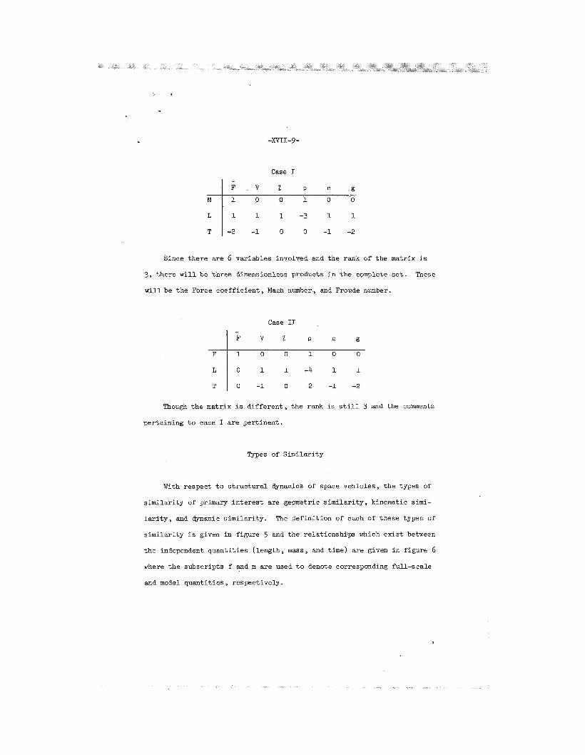
Case I
1 1 1 - 3 1 1
-2 -1 0 0 -1 -2
Since the re are 6 var iables involved and the rank of t he matrix is
3, the re w i l l be th ree dimensionless products i n t h e complete s e t . These
will be t h e Force coe f f i c i en t , Mach number, and Froude number.
Case I1
-4
2 -1 -2
Though t h e matrix i s d i f f e r e n t , the rank is s t i l l 3 and the comments
per ta ining t o case I a re per t inent .
Types of Similar i ty
With respect t o s t r u c t u r a l dynamics of space vehicles , t he types of
s i m i l a r i t y of primary i n t e r e s t are geometric s i m i l a r i t y , kinematic s i m i -
l a r i t y , and dynamic s imi l a r i t y . The de f in i t i on of each of these types of
s i m i l a r i t y i s given i n f igure 5 and the relat ionships which e x i s t between
the independent quan t i t i e s ( length, m a s s , and time) are given i n f igure 6
where t h e subscr ipts f and m are used t o denote corresponding ful l -scale
and model quan t i t i e s , respect ively.

- X v I I - l O -
I n addi t ion t o geometric, kinematic, and dynamic similatiry, i n some
ins tances t h e r e i s a need f o r thermal s imi l a r i t y . However, t h e in t roduct ion
of thermal e f f e c t s may be t r e a t e d as a separa te problem, and is not of prime
importance t o t h e discussion on s t r u c t u r a l dynamics presented herein. The
subjec t of thermal s i m i l a r i t y is discussed i n some d e t a i l i n references 2 ,
3, and 4.
DERIVATION OF SCALE FACTORS FOR STRUCTURAL
DYNAMICS MODELS
Laun ch -Ve h i c l e S t ruc tures
I n the sca l ing of launch-vehicle s t ruc tu res f o r l a t e r a l o r longi tudina l
s t r u c t u r a l dynamics, only dynamic s i m i l a r i t y i s of p r inc ipa l concern. Kin-
ematic s imi l a r i t y i s automatically assured i f dynamic s i m i l a r i t y i s achieved.
Since t h e t e s t s of such models do no t , i n general , involve aerodynamic flows,
geometric s i m i l a r i t y en te r s only i n a gross sense.
La te ra l dynamics. The lateral dynaQics of a l iqu id-propel lan t launch
vehic le involve t h e longi tudina l d i s t r ibu t ions of four p r inc ipa l types of
forces ; namely:
S t ruc tu ra l s t i f f n e s s
S t ruc tu ra l i n e r t i a 2 a u a t 2
nt-
- Fluid s t i f f n e s s m a

Fluid i n e r t i a
where
-xvII-11-
2 rnau a t 2
E1
U
m
- m
a
f l e x u r a l r i g i d i t y of s t r u c t u r e
s t r u c t u r a l bending displacements, or l a t e r a l f l u i d displacements
mass per un i t length of vehic le ( inc ludes s t r u c t u r a l mass p lus pro- pe l l an t mass which moves with t h e s t r u c t u r e )
m a s s of propel lan t per u n i t length of vehic le which moves as a sep- a r a t e degree of freedom and pa r t i c ipa t e s i n f u e l s losh ing
absolu te acce lera t ion of vehic le (includes acce le ra t ion of grav i ty p lus acce lera t ion of vehic le r e l a t i v e t o a f ixed coordinate system)
I f t he d i s t r ibu ted values o f t he r a t i o s o f t hese forces a r e t h e same on
t h e model and fu l l - sca le vehic les , dynamic and kinematic s i m i l a r i t y a r e assured.
I f t h e f l u i d s t i f f n e s s forces a re neglec ted , and2 i s a cha rac t e r i s t i c
length , t h e f l u i d mass may be considered as addi t ive t o t h e s t r u c t u r a l m a s s -
es, and
or
On t h e o ther hand, i f t h e f l u i d s t i f f n e s s i s f e l t t o be important from
t h e standpoint of t h e coupling of f l u i d and s t r u c t u r a l masses, then t h e
s t r u c t u r a l and f l u i d frequencies a r e r e l a t e d as follows :

-xvII-12-
and s ince the s t ruc tu ra l and f l u i d frequencies should bear t he same r a t i o s
on model and fu l l - sca l e veh ic l e s ,
For a r ep l i ca model, t h e quant i ty on t he l e f t i s equal t o h a n d t h e
conditions f o r s i m i l a r i t y a re s a t i s f i e d only i f t h e acce lera t ion f i e l d f o r
t h e model t e s t s is increased by a f a c t o r of y.
also be achieved by any combination of reduction i n s t i f f n e s s or increase
i n mass of t h e model such t h a t t h e product reduces t h e left-hand s i d e of
equation ( 5 ) by x.
However, s i m i l a r i t y can
Longitudinal dynamics. The procedure here is t h e same as f o r lateral
dynamics. The forces are:
S t r u c t u r a l s t i f f n e s s
S t ruc tu ra l i n e r t i a
Fluid s t i f f n e s s
2 m a w a t 2
- m a

Fluid i n e r t i a 2 - a w a t 2
m -
where
EA extensional r i g i d i t y of s t ruc tu re
W s t r u c t u r a l extensional displacements, or longi tudinal f l u i d displace-
ment s
Again i f t h e d i s t r ibu ted values of t h e r a t i o s of these forces are the
same f o r t he model and ful l -scale s t ruc tu res , the conditions fo r dynamic
s i m i l a r i t y are s a t i s f i e d . The sca l e f ac to r s which evolve are the same as
those f o r l a t e r a l dynamics.
Tank pressures. I n t h e case of l icpid-propellant launch vehicles , a
condition f o r s i m i l a r i t y i s t h a t t he s t r e s ses induced by i n t e r n a l ul lagepres-
sure bear t he same r a t i o t o t h e dynamic s t r e s ses f o r the model and proto-
type. It can be r ead i ly shown t h a t t h i s condition is s a t i s f i e d i f t h e model
and fu l l - sca l e ul lage pressures are equal e i the r f o r a r e p l i c a model or f o r
a model designed t o maintain ful l -scale r a t i o s of s t r u c t u r a l frequencies t o
f l u i d frequencies.
Spacecraft Structures
In t he design of o rb i t i ng spacecraf t s t ruc tu res , it is only necessary
t o maintain the ful l -scale d i s t r ibu t ions of mass and s t i f f n e s s throughout.
This condition assures proper simulation of mode shapes and the model t o
ful l -scale frequency r a t i o is read i ly calculated from simple beam, p l a t e ,
o r mass-spring considerations.
However, i f t h e spacecraft is t o land, i t s toppling s t a b i l i t y during

I . .
-XVII-14-
landing i s dependent on the g rav i t a t iona l f i e l d . The condition f o r simu-
l a t i o n then requires t h a t t he r a t i o of t h e i n e r t i a forces t o the gravi ty
forces be invariant or t h a t
where g is t h e accelerat ion due t o gravi ty . 2 - 2
I f t h e model is a r ep l i ca model, ( wm / w f 2 ) = X and s ince
(lm/lf ) = I-’, simulation of t he dynamics during landing requires t h a t
( gm/gf ) = x. Thus, t o model a lunar landing spacecraf t f o r tests on ea r th ,
( gm/gf) = x = 6. If the sca l e is l a r g e r , t he model m u s t be d i s to r t ed or
t h e g rav i t a t iona l f i e l d has t o be reduced by t e s t i n g i n a simulator.
APPLICATIONS OF DYNAMIC MODELS
General Remarks
For p r a c t i c a l reasons, dynamic model s tudies of space vehicles seldom
involve a complete simulation of t h e composite environment-structure system.
Instead, such s tudies are usual ly problem oriented i n t h a t one o r more dyn-
amic models i s designed t o study a s p e c i f i c o r l imi t ed group of r e l a t e d
problems. The log ic o f t h i s approach has several j u s t i f i c a t i o n s among which
are those discussed i n the following sect ions.
Mul t ip l i c i ty of Environmental Conditions
From a dynamics viewpoint, t h e environment of space vehicles may be de-
f ined a s t h e composite of conditions which induce, o r l i m i t dynamic motions
of t h e s t ructure . Those conditions which induce motions, comonly referred

-XVII-15-
t o as the sources of excitation, are of Fundamental importance and will be
discussed f i r s t .
Figure 7 lists the primary sources of excitation of space vehicle struc-
tures . Even a percursory glance at the figure wi l l indicate t o the reader
the d i f f icu l ty of a r e a l i s t i c simulation of those sources of excitation on
any given dynamic model i n a r e a l i s t i c t e s t setup.
has posed severe problems for one or more vehicles, and most vehicles are
Yet, each of the inputs
encumbered by the majority of the inputs. As indicated by the figure, in-
duced responses of the structure become of concern during the manufacturing
and shipping stage, pers is t through ignition, l i f t - o f f , f l i g h t , stage sep-
arat ion, and i n the case of the Apollo vehicle, pose a significant problem
during landing.
During f l igh t through the atmosphere, the sources of excitation are
highly t ransient due t o the s t ructure of the atmospheric wind prof i les , the
dissipation of launch-vehicle fue l , the changes i n character is t ic flows
about the vehicle from subsonic t o transonic t o supersonic, and the changes
i n vehicle structure due t o separation of spent stages.
of these highly t ransient and variable conditions, the spa t ia l and t e m -
poral distributions of the sources of excitation are only approximately
known and hence any one of the environmental effects can only be approxi-
mately simulated. Of significance also is t h e fact tha t , during the f l igh t
phase, nearly a l l of the inputs are superimposed, leading t o a condition
commonly referred t o as "combined environments .'I
As a consequence
The principal phenomenon of importance relat ive t o the limiting of
dynamic motions is damping, and from a s t ructural dynamics veiwpoint, the
principal concern re la t ive t o environmental effects is tha t the thermal
and vacuum environments of space, acting separately o r col lect ively, may

-m1-16-
tend t o reduce the damping of composite structures t o the very low levels
associated with the hysteret ic dissipation of energy i n the s t ruc tura l
materials themselves. Some comments pertinent t o this problem are presented
i n a separate section on damping.
Various Types of Dynamic Models
I n view of the d i f f icu l ty of subjecting a s ingle dynamic model t o the
space vehicle environment and interpreting the full-scale response by scal-
ing up the dynamic model resu l t s , the general approach a t present is t o use
a combination of models t o generate s t ruc tura l , aerodynamic, and propellant
inputs which are integrated i n t o analyt ical programs for prediction of over-
a l l vehicle responses. The types of models used t o accomplish these object-
ions, and the nature of the data obtained are given i n figure 8. I n some
instances, such as for aeroelastic and landing dynamics studies the model
resul ts m a y be scaled t o direct ly indicate full-scale vehicle responses.
I n addition, special purpose models for studying various phenomena and
problem areas are widely used as i n the case of a i rc raf t . Models t o study
control-surface loads, propellant baf f le dampers, and the response of
panels t o acoustic pressures are typical of these.
To date, the application of models t o the study of space vehicle
dynamics has been primarily focused on the launch-vehicle characteristics
with the spacecraft represented as a concentrated m a s s , o r appropriate
aerodynamic shape.
s tudies , current or i n the past , by the Langley Research Center. Details
of the model design character is t ics , research objectives, and t e s t resul ts
are presented i n comparison papers a t t h i s symposium by Reed and Runyan.
As shown by the figure, the models represent both monocoque and cluster
Figure 9 shows some such models u t i l i zed i n various

launch-vehicle configurations, and are used t o study problems involving
s t ruc tura l dynamics , ground winds, and buffeting.
Typical Examples of t h e Use of Structural Dynamics Models
Launch vehicles - Titan 111. Typical samples of the data obtained from
t e s t s of s t ruc tura l dynamics models of launch vehicles are sham i n figure 10
and 11.
Titan 111, t h e vehicle shown i n figure 12.
These data were derived from ear ly t e s t s of a 1/5-scale model of
Figure 10 shows the acceleration of a simulated 45,000-pound p q l o a d i n
the yaw direction ( the longitudinal plane containing the sol ids) f o r a
simulated f l i g h t condition wherein one-half of the mass of the strapped-on
solids is spent. Resonance conditions, exemplified by peak response levels ,
are shown and the f i r s t three natural modes are identified.
exact s t ruc tura l deformations involved have not yet been clearly ident i f ied
the figure also shows the existence of strong resonances a t higher fre-
quencies.
Although the
An interest ing observation from figure 10 is the fact tha t the re-
sponse levels at resonance increase with frequency which indicates tha t ,
since the magnitudes of the force inputs are held essent ia l ly constant, the
damping of the structure-fuel system decreases with frequency.
is substantiated by the logarithmic decay presented i n figure ll which
show tha t the damping of the t h i r d natural mode is only 60 percent as high
as for the f i r s t natural mode and about 80 percent as high as for the second
natural mode.
This trend
The data presented i n figures 10 and 11 represent only a small sample
of the data being generated on t h i s model.
working i n cooperation with the Air Force and Martin-Denver (who designed,
The Langley Research Center, i s

b u i l t , and is jo in t ly tes t ing the model) t o measure the s t ructural dynamics
character is t ics for t h e full range of payloads, inputs, and propellant load-
ings. The t e s t program involves the use of multiple shakers and includes
analysis of both the core and core-plus-solids configurations. It i s hoped
tha t the model t e s t resul ts w i l l provide the necessary checks and modifi-
cations t o the theory so that the full-scale responses can be analyzed
with confidence without the need for extensive dynamic tes t ing of the
full-scale hardware.
Orbiting spacecraft - Nimbus. A s previously mentioned, the use of
dynamic models t o study the experimental aspects of the s t ructural dynamics
of space vehicles has been focused on launch vehicles. The reason for th i s
i s t h a t the great majority of spacecraft i n the past have been small enough
t o permit a full-scale dynamic mockup t o be readily constructed andtes ted ,
o r they have been suff ic ient ly compact tha t the s t ructure could be adequately
restrained from highly undesirable dynamic responses. Ranger and Tiros, re-
spectively, are good examples - A s spacecraft become larger , more f lexible , and more expensive, an
increased need for dynamic model t e s t s w i l l no doubt ar ise .
the Nimbus spacecraft, a future polar orbiting weather s a t e l l i t e shown i n
figure 13, exhibited ccanplex high-amplitude dynamic responses during early
qualification t e s t s wherein the solar panels were folded t o simulate the
launch configuration. A review of the early t e s t resul ts suggested the
need for a simple, inexpensive, dynamic model program t o establish:
A s an example
(1) The character is t ic motions of the vehicle as a function of frequency including natural frequencies, mode shapes, and forced response ;
(2) attaching the spacecraft t o the launch vehicle; and
The re la t ive merits of hard vs. so f t mounting systems for

. 3
-XvII-19-
(31 frequency response.
Sketches of the model and two samples of the t e s t resu l t s , selected
The effectiveness of localized and distributed damping on the
from reference 5 , are shown i n figures 14 and 15.
and as shown i n figure 1 4 , the model
the dynamics of the full-scale structure over the lower frequency range
as desired.
mixed welded and riveted construction.
panels, the model panels were constructed by laminating two thin sheets of
aluminum t o a sheet of balsa.
one s e t the bonding agent used t o laminate the panels was an epoxy resin
( a hard-setting glue) and i n the other se t the bonding agent as a visco-
e l a s t i c damping adhesive.
adhesive effectively reduced the amplification factor (the r a t i o of out-
put t o input accelerations). by nearly an order of magnitude over the
frequency range of primary interest . Other t e s t s a l so demonstrated the
The scale chosen w a s 112,
afforded a reasonable simulation of
The model w a s constructed of standard tubing and plates with
I n l i e u of honeycomb sandwich so la r
Two se ts of panels were constructed. In
Figure 15 shows that the use of t h e damping
effectiveness of isolat ion techniques, and a l l t e s t resul ts were of sub-
s t a n t i a l a id i n the definition of the contributions of the various com-
ponents of the s t ructure t o the overall vehicle motions.
Landing spacecraft - Apollo LEM. A substant ia l research e f for t i s
currently directed t o the analysis o f t h e landing dynamics of space'vehicles
designed t o land on ex t ra te r res t ia l surfaces such as the moon. This re-
search includes both theoret ical and experimental s tudies , and i s oriented
t o es tabl ish both the tipover s t a b i l i t y during the landing process and the
loads and motions generated i n the landing gear during the impact process.
Among the more important variables for such problems is the gravitat-
ional constant. A s shown i n a previous section of the paper, f ree-fal l

-xvII-20-
drop t e s t s of a vehicle on the earth's surface w i l l not simulate landing of
the same vehicle on the moon even though the velocity conditions and the
surface materials at the point of touchdown are the same. The necessary
experimental t e s t resul ts can be obtained by tes t ing full-scale structures
or large dynamic models i n some type of lunar gravi ta t ional simulators, or
by tes t ing 1/6-scale dynamic models.
Gravitational simulators may be of several types such as the inclined
plane, a counter force system which supports 5/6 of the weight of the ve-
h ic le , o r a simulator which permits impacts f o r the velocity and surface
conditions desired onto a surface which is accelerating downward relat ive
t o the earth. A simulator of the l a t t e r type is discussed i n reference
6 and shown i n figure 16.
vehicles, the impact surface would accelerate downward relat ive t o earth
a t 5/6g and the r a t i o of the counter mass M2 t o the simulator mass M would
be such tha t M1 U M 2 .
For simulation of full-scale lunar landing
1
An example of a 1/6-scale dynamic model f o r simulating lunar landing
dynamics i s shown i n figure 17. The basic s t ructure of the model is de-
signed t o readily permit variations i n spacecraft mass and moments of
i n e r t i a by appropriate distribution of added masses t o the basic structure.
Landing-gear configurations can also be varied i n number and s t ructural
detai ls .
the t r ipod having honeycomb shock absorbers t o permit dissipation of the
impact energy with minimum rebound.
under study.
dynamics of luna r spacecraft, the model parameters are selected s o as t o
include values pertinent t o the Apollo LEM vehicle.
The configuration shown has four t r ipod gears with each member of
Other gear configurations a re also
I n addition t o generating basic information on landing

-xvII-21-
DAME'ING
General Remarks
The damping of launch-vehicle and spacecraf t s t ruc tu res i s among t h e
more c r i t i c a l f ac to r s i n the control of t h e i r response t o t h e many types of
inputs .
versely proportional t o damping, and s ince t h e rate of exponential decqy
of f r e e osc i l l a t ions i s d i r e c t l y proportional t o damping, it is necessary
Since the peak amplitudes of forced responses a r e e s sen t i a l ly in-
t o know the inherent damping of the s t ruc tu re i n a l l cases t o p red ic t i t s
response. As a general rule, t h e higher t h e inherent damping t h e b e t t e r ,
and a g rea t dea l of e f f o r t has been expended i n recent years on the dev-
elopment of v i scoe la s t i c f i lms, tapes , sandwiches, e tc . , t o achieve higher
damping.
From t h e viewpoint of simulation, damping i s among t h e more d i f f i c u l t
quan t i t i e s t o scale . Several types of damping a r e of concern including
aerodynamic damping and s t r u c t u r a l damping. Some discussion of each of
t hese as they pe r t a in t o dynamic modeling is presented i n t h e following
paragraphs.
Aerodynamic Damping
Since t h e primary vibrat ions of launch vehicles and spacecraf t occur
during f l i g h t , t he density of t h e air which surrounds the s t r u c t u r a l com-
ponents of t h e vehicles during conditions of peak response is usual ly lower
than ambient conditions at t h e e a r t h ' s surface. Y e t f o r convenience, it i s
highly desirable t o be able t o conduct tests of s t r u c t u r a l dynamic models
under atmospheric conditions.
densi ty on t h e aerodynamic damping of t h e vibrat ions of space vehicles and
Thus t h e question of t h e e f f e c t of air
,
-xvII-22-
t h e i r components ar ises . In addition t o the density e f fec t , the question
of s ize or area of the components a lso exists. In an e f for t t o determine
the effects of these and other variables on the damping of structures for
space vehicle applications, a study of the damping of typical components
was recently conducted a t the Langley Research Center. The study consisted
of measuring the damping of various s izes of c i rcular and rectangular panels,
spheres, and cylinders at air pressures ranging from atmospheric down t o
4 x 10* t o r r . The t e s t components were mounted on the en& of cantilever
beams of different frequencies and the damping was determined by msasuring
the logarithmic decay of the free vibrations of the beam-component systems.
Typical samples of the resul ts are shown i n figure 18, where the r a t i o of
the damping t o the c r i t i c a l damping is plot ted as a function of the press-
ure of the surrounding air medium for a panel and sphere for two amplitudes
of osci l la t ion. For the case shown, the cross-sectional area was 30 square
inches and the frequency of osci l la t ion was 3.8 cycles per second.
results show that the aerodynamic contribution t o the damping of the panel,
obtained by subtracting out the damping at 4 x
t o the amplitude of osci l la t ion and the density of the t e s t medium.
resul ts also show tha t the damping of the sphere i s essent ia l ly proportional
t o density, but independent of amplitude. Other t e s t s involving cylinders
shared the same character is t ic variations as for spheres. In summary the
results of the studies t o data show tha t the damping for panels varies as
follows :
The
t o r r , i s proportional
The
4/3 6 = 2 2 @ +
where

-XVI I-23-
6 damping coe f f i c i en t , 2nc/ccr
P
X amplitude of o s c i l l a t i o n , f t
A area of t h e panel, f t2
m e f fec t ive mass of t h e panel-beam system, slugs
Thus it appears t h a t t he increase i n damping due t o t e s t i n g panel-
density of t h e test medium, s lugs / f t3
type s t ruc tu res i n atmosphere as opposed t o the low-pressure space en-
vironment is d i r e c t l y proport ional t o t h e pressure r a t i o s and can be
readi ly accounted fo r . The same i s t r u e f o r spheres and cylinders. On
t h e other hand, t he r e s u l t s show t h a t t he damping r a t i o f o r a model of
a panel s t ruc tu re t e s t e d i n atmosphere is subs t an t i a l ly less because of
t h e smaller area then it would be for a fu l l - sca l e s t ruc tu re t e s t e d under
s i m i l a r conditions. The damping f ac to r f o r spheres and cyl inders , how-
ever , a r e independent of s i z e and the sca l ing problem is r a the r s t r a igh t -
forward. The essence of these remarks a l so points up the f a c t t h a t t he
low-amplification f ac to r s measured for t e s t s of spacecraf t having l a rge
s o l a r panel arrays may be due t o high aerodynamic damping - a condition
that w i l l not exist during f l i g h t i n low-density regimes.
S t ruc tu ra l Damping
In addition t o t h e aerodynamic damping which may d i s s ipa t e t h e motion
of a s t r u c t u r e , a l l s t ruc tu res possess an i n t e r n a l d i s s ipa t ion mechanism
usual ly r e fe r r ed t o as s t r u c t u r a l damping.
s t r u c t u r a l damping is defined as the composite of those e f f e c t s which in-
volve hys t e re t i c d i s s ipa t ion within the c rys t a l s of t h e s t r u c t u r a l mater-
ials and t h e damping associated with t h e deformation of t h e s t ruc tu re at
i t s jo in t s .
For purposes of this paper,

-XVII-24-
It has long been expected t h a t the damping of s m a l l composite struc-
t u r e s representat ive of aerospace usage would have higher structural damping
than l a rge r s t ruc tu res constructed of t he same materials by t h e same tech-
niques. I n other words, is t h e s t r u c t u r a l damping coeff ic ient of a r ep l i ca
dynamic model inherent ly higher than t h a t f o r t h e ful l -scale s t ruc tu re? I n
an attempt t o answer t h i s question, the Langley Research Center constructed
four aluminum beams with cant i lever supports and t e s t e d them.
had a rectangular cross sec t ion with a width-to-thickness r a t i o of 6 t o 1,
and a length-to-width r a t i o of 10. The l a rges t beam w a s 5 f e e t long. The
cant i lever support f o r each beam consisted of two machined angle blocks de-
signed so t h a t t he s t r e s s e s i n t h e support were consis tent with t h e s t r e s ses
i n t h e beam. The r e l a t i v e sca l e of the models and t h e r e s u l t s of t h e damping
t e s t s are shown i n f igu re 19. The beams were mounted t o a massive s t e e l
and concrete backstop and every precaution was taken t o assure t h a t t he
mounting and t e s t conditions were consis tent .
The beams
During t h e tes ts , t h e clamping pressure of t h e beam supports w a s con-
t r o l l e d by varying the torque applied t o the bolts and f o r a comparative
test condition, t h e clamping pressure fo r all beams was t h e same. The
damping w a s measured f o r both a low torque condition (representat ive of
a semitight f i t ) and a design torque condition.
t h e damping was a l s o measured f o r a range of amplitudes.
For each torque condition,
The r e s u l t s of t h e tests show t h a t t h e damping coe f f i c i en t decreases
as the clamping pressure, j o i n t t i gh tness , or torque is increased, and in-
creases as t h e amplitude of t h e vibrat ion is increased.
g rea t e r importance from t h e standpoint of dynamic modeling of s t ruc tu res is
t h e f ac t t h a t the s t r u c t u r a l damping increased by a f a c t o r of 2 as the sca l e
w a s reduced by a f a c t o r of about 18 f o r design torque conditions and by a
But perhaps of

-XVII-25-
f a c t o r of 4 f o r low torque conditions.
t h a t each beam w a s a r e p l i c a model of t h e other t h ree . On t h e bas i s of
these r e s u l t s , it would appear highly l i k e l y t h a t t h e s t r u c t u r a l d q i n g
of a r e a l i s t i c a l l y s i zed dynamic model of a launch vehicle might d i f f e r
subs t an t i a l ly from t h a t of t h e fu l l - s ca l e s t ruc tu re . Furthermore, t h e
results a l s o emphasize the importance of maintaining close control over
j o i n t t i gh tness and i n t e g r i t y during model construction.
Y e t every attempt w a s made t o assure
Another f a c t o r of concern r e l a t i v e t o the s t r u c t u r a l damping of space-
c r a f t i s the probabi l i ty t h a t long exposure t o space vacuum conditions may
outgas t h e adsorbed gases from the mating surfaces at s t r u c t u r a l j o i n t s and
permit them t o vacuum weld.
assembled s t ruc tu re would approach the inherent damping of t h e mater ia ls - a reduction of one or more orders of magnitude.
i n t h i s case would be t o use welded j o i n t s i n the construction of dynamic
models t o assure t h a t t h e amplification f ac to r s f o r t he fu l l - s ca l e s t ruc tu re
do not exceed those of t he model insofar as s t r u c t u r a l damping is concerned.
In t h i s event the s t r u c t u r a l damping of t h e
A conservative approach
MODEL SUPPORT SYSTEMS
Launch Vehicles
I n essen illy all cases of i n t e r e s t , t he boundary con i t i ons f o r launch
vehicles a re e s sen t i a l ly f ree-free, and an equivalent support systemmust be
used during dynamic model t e s t s t o assure t h a t t h e na tu ra l frequencies, mode
shapes, s t r u c t u r a l damping, and dynamic response of t h e model represent those
which occur on t h e fu l l - sca l e vehicle under f l i g h t conditions. The fundam-
e n t a l c r i t e r i a is one of frequency separation.
support system can be made s u f f i c i e n t l y low compared t o t h e na tu ra l frequency
I f t h e frequency of t h e
-XVII -26-
of the lowest frequency na tu ra l mode of i n t e r e s t , say by a factor of 3
octaves, t he e f f e c t of t h e support system on t h e s t r u c t u r a l cha rac t e r i s t i c s
of t he model can usually be neglected.
If t h e s t ruc tu re of t he vehicle is such t h a t it may be handled a s a
un i t and can be or iented horizontal ly , t h e b e t t e r approach i s usual ly t o
support it as shown i n f igure 20. I n t h i s type of support system, t h e ef-
f e c t of t he support is secondary, and i f , i n the exci ta t ion of t h e natural
modes of t he s t ruc tu re , the supports are located a t the nodal points , t h e i r
e f f e c t on the s t ruc tu re i s negl igible . It i s usual ly desirable t o mount
t he exc i t e r near an anti-node t o maximize the response of t h e s t ruc tu re
i n the mode of i n t e r e s t . However, i f t he response of t h e vehicle in-
dicates coupling of other modes, such coupling can be minimized by mounting
t h e exc i t e r at a node point of t he mode producing t h e undesired coupling
e f f e c t .
In general , t he support cables should be made of e l a s t i c shock cord
but the r e s u l t s of many tests of s m a l l solid-propellant rocket vehicles
at t h e Langley Research Center indicate t h a t s t e e l cables can be used
successful ly i f properly adjusted. In most cases, a two-point support i s
adequate f o r such vehicles, t h e locat ion of these supports being adjusted
t o coincide with nodal points of the mode being excited.
In some cases, pa r t i cu la r ly those involving vehicles containing
l i q u i d propel lants and t h i n pressurized s h e l l s , it i s necessary t o o r i en t
t h e vehicle v e r t i c a l l y t o properly simulate the e f f e c t s of t h e ea r th ' s
g rav i t a t iona l f i e l d on the dynamics of t he vehicle-propellant system.
Robert W. Herr of t he Langley Research Center has s tudied this problem,
reference 7 , and has developed two unique and very e f f ec t ive support systems
which are shown i n f igu re 21. Both of these systems closely dupl icate t h e
, f

u -xv11-27-
free-free boundary conditions f o r such vehicles.
The f i r s t of these v e r t i c a l support systems is re fe r r ed t o as a high-
bay harness. The weight of the vehicle i s ca r r i ed by two support cables
which are attached t o the bottom of the vehicle and t o t h e overhead support
s t ruc tu re . S t a b i l i t y i s achieved by two horizontal r e s t r a in ing cables t i e d
between t h e support cables and the periphery of t he vehicle at some po in t ,
e.g., above the vehicle 's center of gravity. This support system has
e s sen t i a l ly two degrees of freedom i n t h e plane normal t o the cables - t r ans l a t ion as a pendulum and pitching. I n terms of t he dimensions
shown on t h e f igu re , t he s t i f f n e s s , and thus the frequency, of the pitch-
ing mode can be control led by separation of t he points where the support
cables f a s t en t o t h e r i g i d support s t ruc tu re . The vehicle w i l l s tand e rec t
i f
and the frequency of t h e pi tching mode w i l l approach zero as
a + f (,-,)+b b e
1
This support system was used successful ly on t h e l /5-scale SAl-Block I , and
t h e l/kO-scale SATURN V dynamic models s tudied at the Langley Research
Center.
I n some instances involving the tests of very l a rge dynamic models or
a l l - s c a l e launch-vehicle s t r u c t u r e s , it may be d i f f i c u l t t o provide an
overhead r i g i d support s t ruc tu re as necessary f o r t he high-bay harness.
such cases, t h e low-bay harness, though s l i g h t l y more complicated is
I n

C .
-XVII -28-
preferable and i s being used for the s t ructural dynamics studies of the
f i l l -scale Thor-Agena launch vehicle t o be conducted at Langley i n the
near future. As w a s the case f o r the high-bay harness, the weight of the
vehicle is carried by two support cables. However, i n t h i s case the
support cables may be much shorter than the length of the vehicle.
vehicle i s held erect by controlling the tensions i n the restraining
cables by means of turnbuckles, and the condition for neutral s t a b i l i t y ,
and hence, zero frequency i n pi tch, i s
The
Although it is s t i l l necessary t o have some support s t ructure near the top
of the vehicle, t h i s structure can be relat ively l igh t since it need sup-
port only a small fraction of the weight of the vehicle.
Spacecraft
Since the majority of spacecraft are s m a l l r e la t ive t o the s ize of
launch vehicles, the support of spacecraft models for dynamic studies can
be accomplished with comparative ease. Since spacecraft are usually mount-
ed t o the launch vehicles i n semirigid fashion, the in-flight support system
i s closely representative of fixed-free boundary conditions. Hence the
general procedure is t o r igidly fasten the spacecraft t o the exciter fo r
t e s t s along the longitudinal o r f l igh t axis , and t o attach the spacecraft
t o a slippery tab le f o r excitation of l a t e r a l modes and frequencies.
i s important t o recognize, however, that the impednance of the support system,
whether it be the exci ter o r slippery tab le , w i l l d i f fe r from that of the
launch vehicle, and proper consideration of th i s fact should be exercised
It

-xvTI-29-
during in t e rp re t a t ion of the response data obtained during vibrat ion t e s t s
of spacecraf t or spacecraf t models.
CONCLUDING REMARKS
During recent yea r s , dynamic models have been used t o good advantage
f o r solut ion of some of t he problems r e l a t ed t o s t r u c t u r a l dynamics of
space vehicles. Because of t h e s i z e , complexity, and cost of t he s t ruc-
tures and the var iable environments which cons t i t u t e t h e s t r u c t u r a l loads,
it appears t h a t current trends which involve the construction and t e s t i n g
of special ized models f o r analysis of s t r u c t u r a l cha rac t e r i s t i c s , and re-
sponses t o ground winds, wind shear , buffet ing, and f u e l sloshing loads
w i l l continue i n the foreseeable future. Much add i t iona l work is nec-
essary t o understand the e f f ec t s of the highly t r ans i en t nature of s t ru-
c t u r a l propert ies and loading conditions, and t o e s t ab l i sh appropriate
modeling techniques f o r their simulntion and analysis . Pa r t i cu la r a t t en t ion
is needed i n t h e areas of simulation of t h e coupling of propel lant systems
with the s t ruc tu re t o avoid i n s t a b i l i t i e s such as the POGO osc i l l a t ions .
A s pointed out i n the paper, ca re fu l a t t en t ion must be given t o pro-
pe r simulation of both aerodynamic and s t r u c t u r a l damping i n model design
and t e s t i n g . Proper support of launch-vehicle models t o simulate f ree-f l ight con-
d i t i ons during tests i s important, and methods a re presented i n the paper
which have proven t o be adequate and simple.
I n seve ra l areas of concern such as f u e l s loshing and lunar landing,
g rav i ty i s an important var iable .
employed t o simulate gravi ty e f f e c t s are discussed.
Some of t he techniques which may be

-XVII -30 -
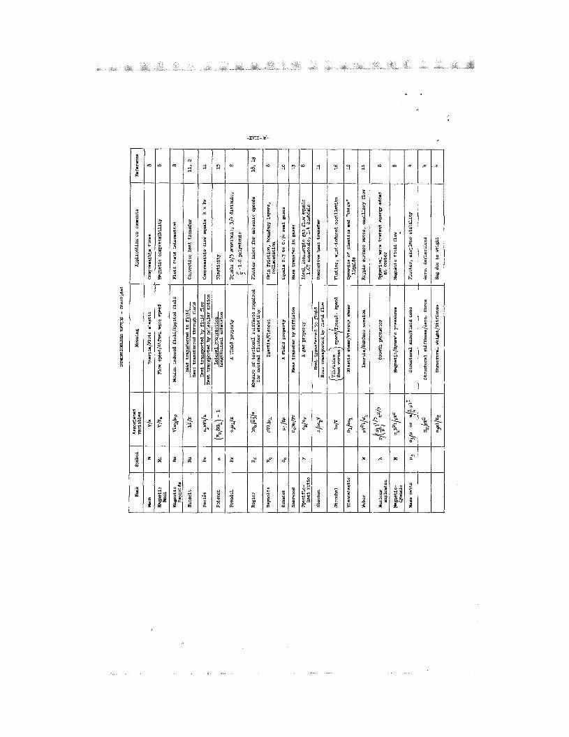
APPENDIX
DIMENSIONLESS RATIOS
The dimensionless r a t i o s which pe r t a in t o f l u i d and f l i g h t dynamics
are summarized i n the following t ab le . The var iables which a re combined
t o form t h e various r a t i o s are defined i n t h e symbols, which a r e presen-
t e d at the end of t h i s appendix. Insofar as possible , per t inent referen-
ces are given which relate t o t h e i r der ivat ion and use.

-XVII-31-
r ( Z, m , t3 Symbols and definition I T , Q
dimens ion
SYMBOIS FOR DIMEWSImLESS RATIOS
. . . . . . . . . . . . . . a sonic speed
B magnetic induction f i e l d . . . . . . . . b semichord . . . . . . . . . . . . . . . e specif ic heat at constant pressure . . . c specif ic heat at constant volume . . . . D coeff ic ient of se l f -d i f f i s i r i ty . . . . E~ energy . . . . . . . . . . . . . . . . .
modulus of e las t ic i ty i n tension . . . .
P
v
F f o r c e . . . . . . . . . . . . . . . . . G~
modulus of e l a s t i c i t y i n torsion . . . . g gravitational acceleration . . . . . . . h heat transfer/area/time/temperature . . k Thermal conductivity . . . . . . . . . . 2 reference length . . . . . . . . . . . .
Z l t
m/Qt
Z
?/t2T
12/t2T
z 2/t
mZ2/t2
m / Z t 2
m l/t2
m / Z t 2
2/t2
m/t3T
mz/t3T
2
m u n i t of mass . . . . . . . . . . . . . . m mass flow ra te . . . . . . . . . . . . . 5 mass flow ra te . . . . . . . . . . . . . p loca l s t a t i c pressure . . . . . . . . .
c r i t i c & or vapor pressure . . . . . . . pc
Q unit of e l e c t r i c charge of flux . . . . Q1 heat added at constant pressure . . . .
L length of mean free path, - 16 - '1 . .I 2 p m
m
m / t
m / t
m / l t 2
m / Z t 2
Q m Z 2 / t 2
c
Frequently
dimension
f t / sec
f t
Btu/lb -OR
Btu/lb-OR
f t -1b
2 lb/ in .
l b
lb / in .
f t / sec
Btu/ft2/sec/OR
2
2
I E t u/hr-f t - O R
f t
f t
2 lb-see / f t
slugs / s ec
&-sec/ft
l b / f t 2
l b / d
coulombs
Btu

-XVII-32-
Symhol and defini t ion
9
R
r
T
t
V
'a
5
u1
u2
P
u1
u2
u3 w
w a
dynamic pressure . . . . . . . . . . . . universal gas constant . . . . . . . . . radius . . . . . . . . . . . . . . . . . t emperat w e . . . . . . . . . . . . . . time . . . . . . . . . . . . . . . . . . speed . . . . . . . . . . . . . . . . . Alfven wave speed, K- - * - . -
v2p
coefficient of thermal expansion . . . . coefficient of viscosity, abs . . . . . magnetic permeability . . . . . . . . . mass density . . . . . . . . . . . . . . coefficient of surface tension . . . . . e lec t r ica l conductivity . . . . . . . . . s t ruc tura l density . . . . . . . . . . . frequency . . . . . . . . . . . . . . . tors ional frequency . . . . . . . . . .
dimension
Frequently used
dimension
l b / f t 2
f t
OR
s ec
i't/sec
f t / sec
in./in.-'R 2
lb-sec/ft
2 4 lb-sec /it
dynes /cm
i't310h 2 1 lb-sec / f t
radlsec
rad/sec

-XVII-33-
REFERENCES
1. LangJlarr, Henry L. : Dimensional Analysis and Theory of Models. John Wiley & Sons, Inc . , 1951, Chapter 3.
2. Katzoff, S.: Simulatude i n Thermal Models of Spacecraft . NASA TN D-1631, 1963.
3. O'Sullivan, W i l l i a m J., Jr., Theory of Aircraf t S t r u c t u r a l Models Subject t o Aerodynamic Heating and External Loads. NACA TN 4115, 1957.
4. Molyneux, W. G. : Scale Models f o r Thermo-Aeroelastic Research. C. P. 579, Br i t i sh A.R.C., 1962.
5. Carden, Huey D . , and Herr, Robert W. : Vibration Studies on a Simplified 1/2-Scale Model of the Nimbus Spacecraft . Shock, Vibration, and Associated Environments. Washington, D. C . , Decem- be r 3-5, 1963.
Thir ty- third Symposium on
6. Brooks, George W . : Techniques f o r Simulation and Analysis of Shock and Vibration Environments of Space Fl ight Systems. ASME Shock and Vibration Colloquium, New York. Nov. 27, 1962, edi ted by W i l l J . Worley.
7. Herr, Robert W . , and Carden, Huey D.: Support Systems and Exci ta t ion Tech- niques f o r Dynamic Models of Space Vehicle Structures . Symposium on Aeroelastic and Dynamic Modeling Technology, A I A FiTD-TDR-63-4197, Par t 1. Dayton, Ohio, September 23-25, 1963, pp. 249-277.
8. S t r e e t e r , Victor L.: Handbook of Fluid Dynamics. McGraw-Hill Book Co., Inc. , New York, F i r s t ed. , 1961.
9. von Karman, Theodore: Fundamental Equations i n Aerothermochemistry. From Butterworth's S c i e n t i f i c Publ icat ions, Selected Combustion Problems, 11.
London, 1956.
10. Neihouse, Anshal I . , and Pepoon, Ph i l ip : Dynamic Simili tude Between a Model and a Full-Scale Bo& f o r Model-Investigation at a Full-scale Mach Number. NACA TN 2062, 1950.
11. Ipsen, D. C.: Units, Dimensions, and Dimensionless Numbers. McGraw-Hill Book Co., Inc . , New York, 1960, Chapter 12.
12. Alfrey, Turner, Jr.: Mechanical Behavior of High Polymers. Interscience Publishers, Inc., New York, 1948.
13. Kreith, Frank: Principles of Heat Transfer. I n t . Textbook Co. (Scrmton, Pa. 1 , c.1958.
14. Bisplinghoff, R. L., Ashley, H. , and Halfman, R. L.: Aeroelast ic i ty . Adaison-Wesley Publishing Co., Inc., Cambridge, Mass., 1955, p. 561.

-xvII 34-
15. Timoshenko, S. , and Goodier, J. N.: Theory of E la s t i c i ty . McGraw- Hill Book Co., Inc.. New York, Second Ed., 1951, p. 9.
16. Harris, Cyril M . : Handbood of Noise Control. McGraw-Hill Book Co., Inc . , 1957, Chapter 33, p. 18.
17. Eide, Donald G.: Preliminary Analysis of Variation of P i t ch Motion of a Vehicle i n a Space Environment Due t o Fuel Sloshing i n a Rectangular Tank. NASA TN D-2336, 1964.
18. Frueh, Frank J.: A F l u t t e r Design Parameter t o Supplement the Regier Number. AIAA Jour., Vol. 2 , no. '7, July 1964.
19. Harris, G. , and Head, A. L., Jr.: F l u t t e r Criteria for Preliminary Design. Engineering Report 2-53450/3R467. Chance Vought Corp., A Division of Ling-Temco Vought , Inc. , Dallas 22, Texas, September 1963. (CONFIDENTIAL)

l t m
-m1-36-
__
N
k