for iso 21434 - fortiss
TRANSCRIPT

for ISO 21434
Security Engineering
White Paper
2
Security Engineering – for ISO 21434
Authors
Yuri Gil Dantas
fortiss GmbH, Guerickestr. 25 80805 München
Dr. Vivek Nigam
fortiss GmbH, Guerickestr. 25 80805 München
Dr. Harald Rueß
fortiss GmbH, Guerickestr. 25 80805 München
3
Content
Abstract 4
Introduction 5
ISO 21434 at a Glance 7
Running Example 9
Incremental Approach 14
Approach by Example 16
Related Work 21
Next Research Directions 22
Conclusion 23
References 24
Imprint 26
4
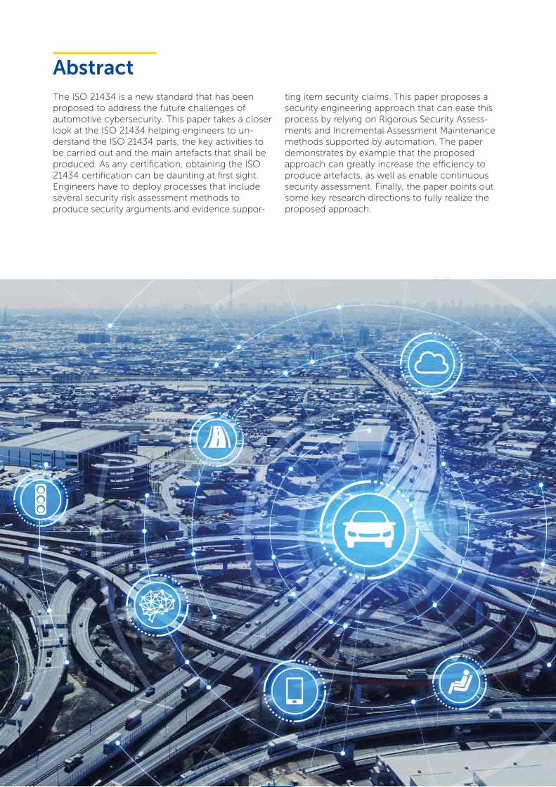
AbstractThe ISO 21434 is a new standard that has been proposed to address the future challenges of automotive cybersecurity. This paper takes a closer look at the ISO 21434 helping engineers to un-derstand the ISO 21434 parts, the key activities to be carried out and the main artefacts that shall be produced. As any certification, obtaining the ISO 21434 certification can be daunting at first sight. Engineers have to deploy processes that include several security risk assessment methods to produce security arguments and evidence suppor-
ting item security claims. This paper proposes a security engineering approach that can ease this process by relying on Rigorous Security Assess-ments and Incremental Assessment Maintenance methods supported by automation. The paper demonstrates by example that the proposed approach can greatly increase the efficiency to produce artefacts, as well as enable continuous security assessment. Finally, the paper points out some key research directions to fully realize the proposed approach.
5
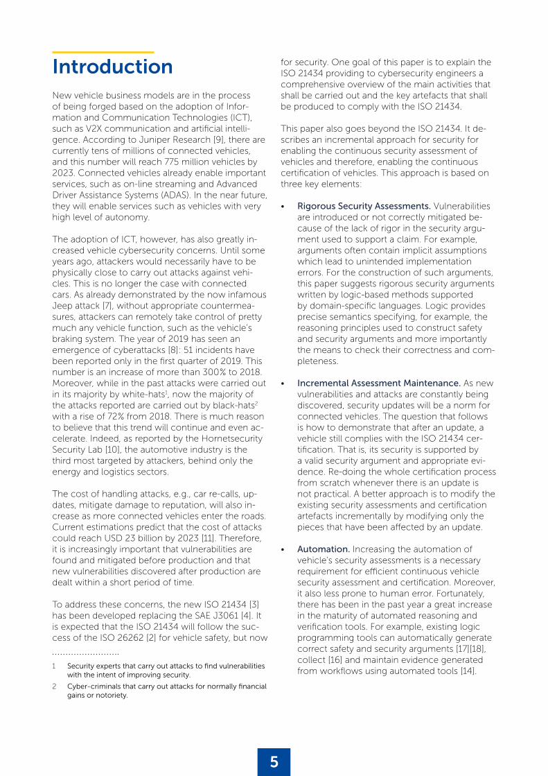
IntroductionNew vehicle business models are in the process of being forged based on the adoption of Infor-mation and Communication Technologies (ICT), such as V2X communication and artificial intelli-gence. According to Juniper Research [9], there are currently tens of millions of connected vehicles, and this number will reach 775 million vehicles by 2023. Connected vehicles already enable important services, such as on-line streaming and Advanced Driver Assistance Systems (ADAS). In the near future, they will enable services such as vehicles with very high level of autonomy.
The adoption of ICT, however, has also greatly in-creased vehicle cybersecurity concerns. Until some years ago, attackers would necessarily have to be physically close to carry out attacks against vehi-cles. This is no longer the case with connected cars. As already demonstrated by the now infamous Jeep attack [7], without appropriate countermea-sures, attackers can remotely take control of pretty much any vehicle function, such as the vehicle’s braking system. The year of 2019 has seen an emergence of cyberattacks [8]: 51 incidents have been reported only in the first quarter of 2019. This number is an increase of more than 300 % to 2018. Moreover, while in the past attacks were carried out in its majority by white-hats1, now the majority of the attacks reported are carried out by black-hats2 with a rise of 72 % from 2018. There is much reason to believe that this trend will continue and even ac-celerate. Indeed, as reported by the Hornet security Security Lab [10], the automotive industry is the third most targeted by attackers, behind only the energy and logistics sectors.
The cost of handling attacks, e. g., car re-calls, up-dates, mitigate damage to reputation, will also in-crease as more connected vehicles enter the roads. Current estimations predict that the cost of attacks could reach USD 23 billion by 2023 [11]. Therefore, it is increasingly important that vulnerabilities are found and mitigated before production and that new vulnerabilities discovered after production are dealt within a short period of time.
To address these concerns, the new ISO 21434 [3] has been developed replacing the SAE J3061 [4]. It is expected that the ISO 21434 will follow the suc-cess of the ISO 26262 [2] for vehicle safety, but now
1 Security experts that carry out attacks to find vulnerabilities with the intent of improving security.
2 Cyber-criminals that carry out attacks for normally financial gains or notoriety.
for security. One goal of this paper is to explain the ISO 21434 providing to cybersecurity engineers a comprehensive overview of the main activities that shall be carried out and the key artefacts that shall be produced to comply with the ISO 21434.
This paper also goes beyond the ISO 21434. It de-scribes an incremental approach for security for enabling the continuous security assessment of vehicles and therefore, enabling the continuous certification of vehicles. This approach is based on three key elements:
• Rigorous Security Assessments. Vulnerabilities are introduced or not correctly mitigated be-cause of the lack of rigor in the security argu-ment used to support a claim. For example, arguments often contain implicit assumptions which lead to unintended implementation errors. For the construction of such arguments, this paper suggests rigorous security arguments written by logic-based methods supported by domain-specific languages. Logic provides precise semantics specifying, for example, the reasoning principles used to construct safety and security arguments and more importantly the means to check their correctness and com-pleteness.
• Incremental Assessment Maintenance. As new vulnerabilities and attacks are constantly being discovered, security updates will be a norm for connected vehicles. The question that follows is how to demonstrate that after an update, a vehicle still complies with the ISO 21434 cer-tification. That is, its security is supported by a valid security argument and appropriate evi-dence. Re-doing the whole certification process from scratch whenever there is an update is not practical. A better approach is to modify the existing security assessments and certification artefacts incrementally by modifying only the pieces that have been affected by an update.
• Automation. Increasing the automation of vehicle’s security assessments is a necessary requirement for efficient continuous vehicle security assessment and certification. Moreover, it also less prone to human error. Fortunately, there has been in the past year a great increase in the maturity of automated reasoning and verification tools. For example, existing logic programming tools can automatically generate correct safety and security arguments [17][18], collect [16] and maintain evidence generated from workflows using automated tools [14].
6
Benefits. The benefits of the proposed approach with respect to existing approaches are two-fold. Firstly, rigorous security assessments with precise semantics enable the automated checking of when an argument is incomplete, e. g., some threats are not appropriately mitigated, or plain wrong. More-over, since the methods are based on logic, engi-neers can query specifications like the following ones:
Have all the identified threats been adequately mitigated? If not, which ones remain?
Which architecture options with additional countermeasures can I use to mitigate the threats that have not yet been mitigated?
What are the impacts of a particular design on other issues such as safety and performance? Will the new countermeasure affect some sa-fety assumption, e. g., increased communica-tion latency?
What is the security argument used to support the security claim of an item?
Secondly, the use of incremental methods and automation greatly increases the efficiency of re- certification in terms of time and cost. Efficiency is key for enabling continuous certification. Other-wise, the overhead costs of recertification are very high without adequate automation. This has been observed, for example, in the avionics domain, where the change of a single line of code can imply costs of in the order of millions of USD.3
The target audience for this paper is all cybersecuri-ty engineers who are interested in the ISO 21434 itself and in an approach that enables the conti-nuous certification for automotive vehicles. It is expected that, by reading this paper, cybersecurity engineers will be able to obtain a clearer picture of the ISO 21434, especially of the activities performed during the risk assessment. It is also expected that cybersecurity engineers will both learn that parts of the ISO 21434 may be automated by suitable tech-niques as well as get a perspective on how to build continuous certification for automotive vehicles using an incremental approach.
Section 1 provides an overview of the ISO 21434, and Section 3 focuses more on the parts related to risk assessment and concept phase. Section 4 describes an approach for the continuous vehicle assessment and certification. Section 5 demonstra-tes this approach through an illustrative example described in Section 2. After a discussion of related work in Section 6, Section 7 lists the key research directions to fully realize the proposed approach. The paper is concluded in Section 8.
3 Stated by the DARPA project coordinator https://www.youtube.com/watch?v=bXuBm_awZvg

7
ISO 21434 at a GlanceAs with the ISO 26262, the ISO 21434 is structured into multiple parts (a.k.a. clauses) that tackle diffe-rent aspects of cybersecurity. The technical parts of the ISO 21434 are depicted in Figure 1. These parts are preceded by parts defining the scope (Part 1), the normative references (Part 2), the terms and abbreviations (Part 3) and general considerations (Part 4).
Figure 1 provides an overview of all the technical parts. Section 3 goes into more detail regarding Parts 8 (Risk Assessment Methods), and 9 (Concept Phase).
In a nutshell, Parts 5 and 6 contain the require-ments for organizational cybersecurity. Parts 7 and 8 describe activities and methods that can be used during the lifecycle of a product to ensure the
security of items. Part 9 details the requirements during concept phase. Parts 10 and 11 detail the requirements during production, while Parts 12–14 detail the requirements during the post-production. Finally, Part 15 details the requirements for supplier management.
Part 5. This part details the requirements for build-ing and maintaining a cybersecurity culture and governance. This is accomplished by setting cyber-security policies, rules and processes for overall cy-bersecurity management and for project dependent cybersecurity management. The policies and rules for the overall cybersecurity management shall (1) define the organization-specific rules and processes for cybersecurity, e. g., the executive management’s commitment to manage security risks; (2) assign responsibilities for security activities; (3) support the implementation of cybersecurity; (4) institute and maintain cybersecurity culture; (5) perform organi-zational cybersecurity audits; (6) manage the sha-
PART 5 Overall Cybersecurity Management
PART 6 Project Dependent Cybersecurity Management
PART 7 Continuous Cybersecurity Activities
PART 8
CONCEPT PHASE PRODUCTION PHASE POST-PRODUCTION PHASE
Risk Assessment Methods
PART 15 Distributed Cybersecurity Activities
PART 9Concept Phase
PART 10Product Development
PART 11Cybersecurity Validation
PART 12Production
PART 14Decommissioning
PART 13Operations and Maintenance
Figure 1. Technical parts of the ISO 21434.
8
ring of cybersecurity information; (7) institute and maintain management systems that support cyber-security activities; (8) and provide evidence that the tools used do not adversely affect cybersecurity.
Part 6. This part describes the requirements for the management of cybersecurity activities for the de-velopment of a specific project. The key objectives of these requirements are (1) assign the responsibili-ties for cybersecurity activities; (2) plan the cyberse-curity activities; (3) create a cybersecurity case that provide the high-level argument for the achieved degree of cybersecurity.
Part 7. This part details cybersecurity activities that can be performed at any stage of the lifecycle. The main objective of these requirements are (1) to col-lect relevant cybersecurity information; (2) to triage collected cybersecurity information; (3) to assess cybersecurity events; (4) to identify and analyze cy-bersecurity vulnerabilities; (5) to manage identified cybersecurity vulnerabilities.
Part 8. This part details methods that organizations can use to determine the risks to stakeholders of cybersecurity threats. The main objectives of the methods are to (1) identify assets; (2) identify threat scenarios; (3) rate the impact; (4) identify or update the attack paths for threat scenarios; (5) assess the ease with which the identified attack paths can be exploited; (6) determine the risk value of a threat scenario; and (7) select the appropriate risk treat-ment.
Part 9. This part details the requirements for the concept phase. Its main objectives are (1) define the item, the operational environment and its interac-tion with other items; (2) specify cybersecurity goals and cybersecurity claims; and (3) specify cybersecu-rity requirements and allocate them to the item or to the operational environment.
Part 10. This part details the requirements for the product development. The main objectives of this part are to (1) specify refined cybersecurity require-ments and architectural design; (2) verify that the refined cybersecurity requirements and architectu-ral design comply with cybersecurity requirements from a higher level; (3) identify vulnerabilities in the design and manage them accordingly; (4) provide evidence that the component complies with the cybersecurity specification and does not contain undesired functionality regarding cybersecurity.
Part 11. This part details the activities for cyberse-curity validation that are performed after the integ-ration of components. Its main objectives are (1) to validate the cybersecurity goals and claims;
(2) to confirm that the item satisfies the cyberse-curity goals; (3) to confirm that the residual risk is acceptable.
Part 12. This part details the requirements during the fabrication, assembly and configuration of an item or component. Its objectives are (1) to apply the cybersecurity requirement for post-develop-ment to the item or component; and (2) to prevent the introduction of vulnerabilities during production.
Part 13. This part describes the requirements for cybersecurity incident response and updates. Its objectives are (1) to handle cybersecurity events that become a cybersecurity incident; and (2) to preserve cybersecurity during and after updates to items or components post-production.
Part 14. This part details the requirements on de-commissioning of an item or component. The main objective is to ensure that the item or component is decommissioned in a secure manner.
Part 15. This part details the requirements for distri-buted cybersecurity activities. The main objective of these requirements is to define the interactions, dependencies, and responsibilities between custo-mers and suppliers for cybersecurity activities.
Section 4 describes the proposed approach and how this approach can help to achieve the objec-tives of Parts 8, 9 and 10 in an automated fashion. ISO 21434 has several appendixes that illustrate how the ISO 21434 could be used in practice. Section 5 illustrates the proposed approach using the running example in the ISO 21434, Annex G. This running example is described in Section 2.
9
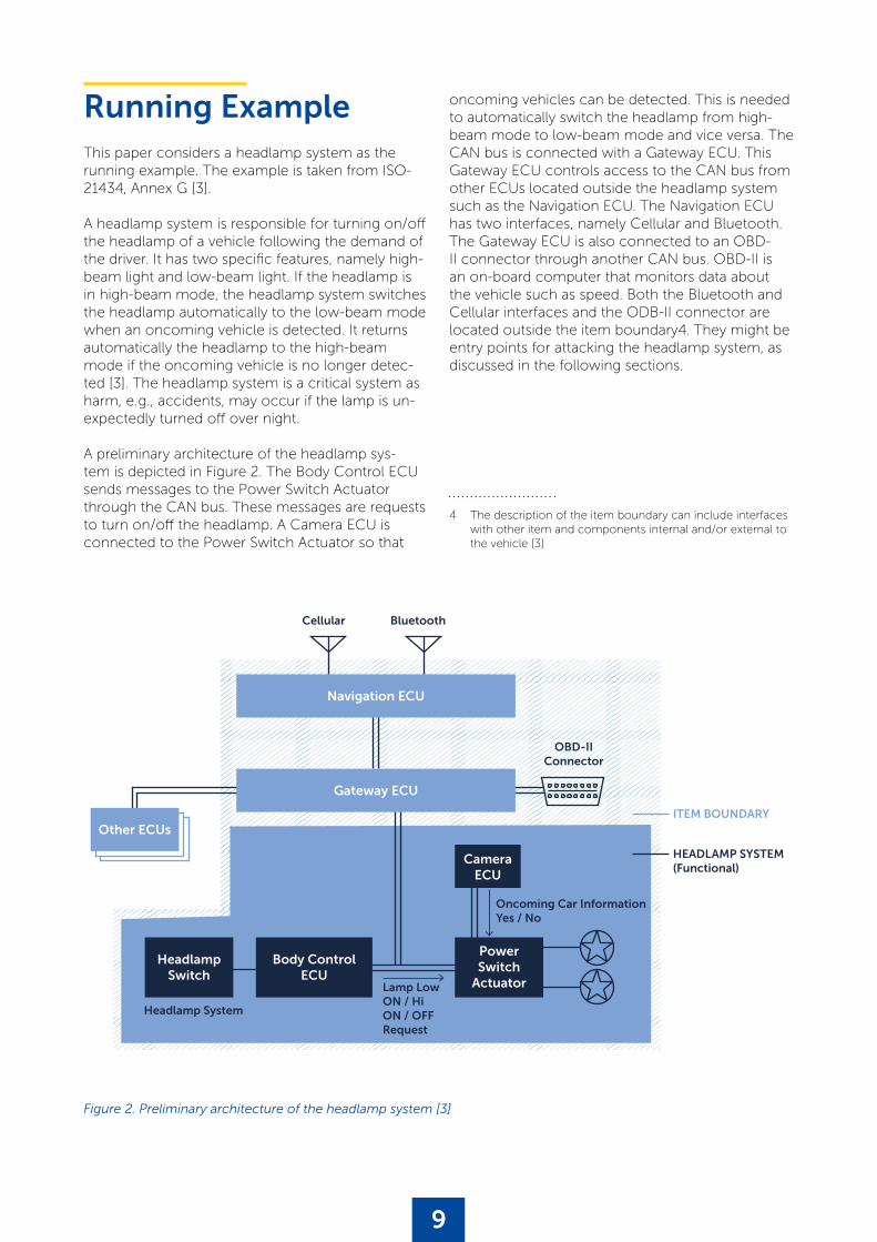
Running ExampleThis paper considers a headlamp system as the running example. The example is taken from ISO-21434, Annex G [3].
A headlamp system is responsible for turning on/off the headlamp of a vehicle following the demand of the driver. It has two specific features, namely high-beam light and low-beam light. If the headlamp is in high-beam mode, the headlamp system switches the headlamp automatically to the low-beam mode when an oncoming vehicle is detected. It returns automatically the headlamp to the high-beam mode if the oncoming vehicle is no longer detec-ted [3]. The headlamp system is a critical system as harm, e. g., accidents, may occur if the lamp is un-expectedly turned off over night.
A preliminary architecture of the headlamp sys-tem is depicted in Figure 2. The Body Control ECU sends messages to the Power Switch Actuator through the CAN bus. These messages are requests to turn on/off the headlamp. A Camera ECU is connected to the Power Switch Actuator so that
oncoming vehicles can be detected. This is needed to automatically switch the headlamp from high-beam mode to low-beam mode and vice versa. The CAN bus is connected with a Gateway ECU. This Gateway ECU controls access to the CAN bus from other ECUs located outside the headlamp system such as the Navigation ECU. The Navigation ECU has two interfaces, namely Cellular and Bluetooth. The Gateway ECU is also connected to an OBD-II connector through another CAN bus. OBD-II is an on-board computer that monitors data about the vehicle such as speed. Both the Bluetooth and Cellular interfaces and the ODB-II connector are located outside the item boundary4. They might be entry points for attacking the headlamp system, as discussed in the following sections.
4 The description of the item boundary can include interfaces with other item and components internal and/or external to the vehicle [3]
Navigation ECU
Cellular Bluetooth
Gateway ECU
Other ECUs
CameraECU
HeadlampSwitch
Headlamp System
Lamp LowON / HiON / OFFRequest
Oncoming Car InformationYes / No
ITEM BOUNDARY
HEADLAMP SYSTEM(Functional)
OBD-IIConnector
PowerSwitch
Actuator
Body ControlECU
Figure 2. Preliminary architecture of the headlamp system [3]
10
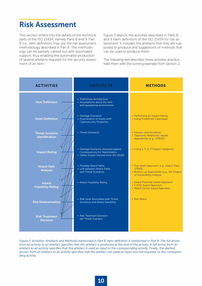
Risk AssessmentThis section enters into the details of the technical parts of the ISO 21434, namely Parts 8 and 9. Part 9 (i.e., item definition) may use the risk assessment methodology described in Part 8. This methodo-logy can be partially carried out with automated support, thus enabling the automated production of several artefacts required for the security assess-ment of an item.
Figure 3. Activities, Artefacts and Methods mentioned in Part 8. Item definition is mentioned in Part 9. The full arrow from an activity to an artefact specifies that this artefact is produced at the end of the activity. A full arrow from an artefact to an activity specifies that this artefact is used as input to the corresponding activity. Finally, the dashed arrows from an artefact to an activity specifies that the artefact can used as input, but not required, to the correspon-ding activity.
Figure 3 depicts the activities described in Parts 8 and 9 (item definition) of the ISO 21434 for risk as-sessment. It includes the artefacts that they are sup-posed to produce and suggestions of methods that can be used to produce them.
The following text describes these activities and illus-trate them with the running example from Section 2.
Item Definition
Asset Definition
Risk Determination
Impact Rating
Threat Scenario Identification
Attach Path Analysis
Attach Feasibility Rating
Risk Treatment Decision
ACTIVITIES ARTEFACTS METHODS
• Preliminary Architecture• Assumptions about the item and operational environment
• Damage Scenarios• Enumeration of Assets with Cybersecurity Properties
• Performing an Impact Rating• Using Predefined Catalogues
• Possible Attack Paths• Link between Attack Paths and Threat Scenarios
• Attack Feasibility Rating
• Risk Level Associated with Threat Scenarios and Attack Feasibility
• Risk Treatment Decision per Threat Scenario
• Damage Scenarios Assessed against Consequences for Stakeholders• Safety Impact Derived from ISO 26262
• Threat Scenarios
• Attack Potential-based Approach• CVSS2-based Approach• Attack Vector-based Approach
• Risk Matrix
• Misuse-case Elicitation• Taxonomy Mnemonic-based Approaches (e. g., STRIDE)
• Top-down Approach, e.g., Attack Trees, STRIDE• Bottom-up Approaches (e.g., the Output of Vulnerability Analysis
• Using S, F, O, P Impact Categories
11
Item Definition. This is an early-on activity that defines the item5 whose risk assessment is going to be evaluated. During this activity, a preliminary ar-chitecture of the item is described and the assump-tions about its operational environment.
Example 3.1
Consider the running example from Section 2. The artefacts produced by this activity are the preli-minary architecture of the headlamp system, the description of its architectural elements (a.k.a. func-tions), and the item boundary. These artefacts are described in Section 2.
Asset Identification. From the artefacts produced by the item definition activity, the item’s damage scenarios6 are identified. Moreover, one should also enumerate the identified assets with cybersecurity properties that would lead to a damage scenario. Three methods are suggested by the ISO 21434 for carrying out this activity:
• Impact rating: This method rates the impact of cyberattacks to assets.
• Deriving Assets from Threat Scenarios:7 Threat scenarios (produced in the threat scena-rio activity) can help identify key assets.
• Pre-defined Catalogues: Existing catalogues provide a good source for identifying assets.
Example 3.2
An asset from the headlamp is the CAN bus that transmits messages such as requests to turn on/off the lamp. Cybersecurity properties relevant for the CAN bus include integrity and availability. In tegrity-wise, the CAN bus must ensure the accuracy and completeness of the message transmitted. Availabil-ity-wise, the CAN bus must be available at all times whenever, e. g., the Body Control ECU requests to turn on/off the lamp. Damage scenarios for the CAN bus include unexpected behavior like:
5 An item is a system or combination of systems to imple-ment a function.
6 A damage scenario is an adverse consequence or un-desirable result due to the compromise of a cybersecurity property of an asset
7 A threat scenario is a statement of potential negative actions that lead to a damage scenario.
Unexpected loss of head light: the headlamp turns off during night driving resulting from the loss of integrity of CAN signal
Unable to switch on head light: the Power Switch Actuator does not receive a request from the Body Control ECU to turn on the lamp resul-ting from the loss of availability of the CAN bus.
Threat Scenario Identification. The threat scenarios for each damage scenario shall be identified. Notice that a damage scenario may be associated with multiple threat scenarios. A threat scenario may include the targeted asset, the compromised cyber-security property and the actions that need to be carried out by an attacker to accomplish a damage scenario.
While there is a number of methodologies to carry out this activity [33], the ISO 21434 proposes the use of the two following methods or their combination:
• misuse-case elicitation: Threats scenario can often be identified by using items in an possible, but unintended way.
• taxonomy mnemonic-based approaches, such as STRIDE: Using threat categories enables a systematic identification of threat scenarios. (See [33] for more about this type of technique.)
For this activity, there might be the need for an ad-ditional artefact specifying what type of attacker is being considered. This artefact is important as attacker intentions, (e. g., is he a script-kid, cyber- criminal or an agent supported by a government? and capabili-ties, e. g., which types of channels is he able to hack?) lead to different types of threat scenarios.
Example 3.3
Consider the damage scenarios from Example 3.2. Threat scenarios for Damage Scenarios 1 and 2 can be, respectively:
An attacker spoofing a CAN signal leads to loss of integrity of the CAN message of ‘Lamp request’.
An attacker flooding the CAN bus buffer leads to loss of availability of the CAN bus.
For the Threat Scenario 2, e. g., an attacker could flood the CAN bus with high priority messages so that the lamp switches off requests may be proces-sed with significant delay.
12
This artefact describing the attacker would enable the use of formal approaches to enumerate in an automated fashion threat scenario identification by using precise mathematical models [18, 19, 28, 34]. Section 5 illustrates how automation is a corner-stone for incremental security engineering.
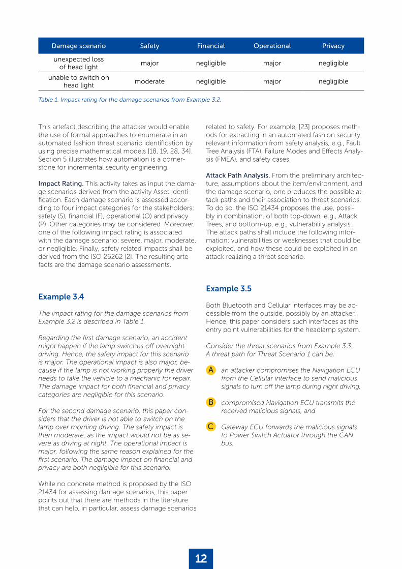
Impact Rating. This activity takes as input the dama-ge scenarios derived from the activity Asset Identi-fication. Each damage scenario is assessed accor-ding to four impact categories for the stakeholders: safety (S), financial (F), operational (O) and privacy (P). Other categories may be considered. Moreover, one of the following impact rating is associated with the damage scenario: severe, major, moderate, or negligible. Finally, safety related impacts shall be derived from the ISO 26262 [2]. The resulting arte-facts are the damage scenario assessments.
Example 3.4
The impact rating for the damage scenarios from Example 3.2 is described in Table 1.
Regarding the first damage scenario, an accident might happen if the lamp switches off overnight driving. Hence, the safety impact for this scenario is major. The operational impact is also major, be-cause if the lamp is not working properly the driver needs to take the vehicle to a mechanic for repair. The damage impact for both financial and privacy categories are negligible for this scenario. For the second damage scenario, this paper con-siders that the driver is not able to switch on the lamp over morning driving. The safety impact is then moderate, as the impact would not be as se-vere as driving at night. The operational impact is major, following the same reason explained for the first scenario. The damage impact on financial and privacy are both negligible for this scenario.
While no concrete method is proposed by the ISO 21434 for assessing damage scenarios, this paper points out that there are methods in the literature that can help, in particular, assess damage scenarios
related to safety. For example, [23] proposes meth-ods for extracting in an automated fashion security relevant information from safety analysis, e. g., Fault Tree Analysis (FTA), Failure Modes and Effects Analy-sis (FMEA), and safety cases.
Attack Path Analysis. From the preliminary architec-ture, assumptions about the item/environment, and the damage scenario, one produces the possible at-tack paths and their association to threat scenarios. To do so, the ISO 21434 proposes the use, possi-bly in combination, of both top-down, e. g., Attack Trees, and bottom-up, e. g., vulnerability analysis. The attack paths shall include the following infor-mation: vulnerabilities or weaknesses that could be exploited, and how these could be exploited in an attack realizing a threat scenario.
Example 3.5
Both Bluetooth and Cellular interfaces may be ac-cessible from the outside, possibly by an attacker. Hence, this paper considers such interfaces as the entry point vulnerabilities for the headlamp system.
Consider the threat scenarios from Example 3.3. A threat path for Threat Scenario 1 can be:
an attacker compromises the Navigation ECU from the Cellular interface to send malicious signals to turn off the lamp during night driving,
compromised Navigation ECU transmits the received malicious signals, and
Gateway ECU forwards the malicious signals to Power Switch Actuator through the CAN bus.
Table 1. Impact rating for the damage scenarios from Example 3.2.
Damage scenario Safety Financial Operational Privacy
unexpected loss of head light
major negligible major negligible
unable to switch on head light
moderate negligible major negligible
13
Note that this very same attack could be also carried out from the Bluetooth interface. Similarly, a threat path for Threat Scenario 2 can be:
an attacker compromises the Navigation ECU from the Bluetooth interface to flood the CAN bus with high priority messages,
compromised Navigation ECU transmits the received malicious messages, and
Gateway ECU forwards the malicious messages to the CAN bus.
Attack Feasibility Rating. Each attack path is rated according to the following categories: high, me-dium, low or very low. The following three methods are suggested for rating attack paths:
• Attack Potential: The rating of an attack path is obtained by evaluating the attack level taking into account core factors required, including elapsed time, specialist expertise and item knowledge required, window of opportunity, and equipment.
• CVSS2: The attack path rating is obtained from common vulnerability scoring systems, e. g., available at https://www.first.org/cvss/.
• Attack vector: The rating is determined by analy zing the predominant attack vector of the attack path.
Example 3.6
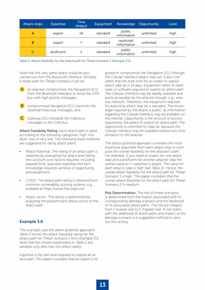
This example uses the attack potential approach. Table 2 shows the attack feasibility rating for the attack path for Threat Scenario 1 from Example 3.5. Note that the chosen parameters in Table 2 are samples only and may not reflect reality.
Expertise is the skill level required to exploit an at-tack path. This paper considers that an expert is re-
quired to compromise the Navigation ECU through the Cellular interface (attack step (a)). It also con-siders that the total time for an expert to exploit attack step (a) is 14 days. Equipment refers to hard-ware or software required to exploit an attack path. The Cellular interface may be readily available and easily accessible by the attacker though, e. g., wire-less network. Therefore, the equipment required for exploiting attack step (a) is standard. The knowl-edge required by the attack is public, as information regarding the Cellular interface may be available on the Internet. Opportunity is the amount of access required by the attack to exploit an attack path. The opportunity is unlimited for step (a), because the Cellular interface may be available without any time limitation to the attacker.
The attack potential approach considers the most expensive argument from each attack step to com-pute the overall feasibility for the attacker’s path. For example, if you need an expert for one attack step and a proficient for another attacker step the overall value w.r.t. expertise is expert. The value for each attack’s step is high (see Table 2). Hence, the overall attack feasibility for the attack path for Threat Scenario 1 is high. This paper considers that the overall attack feasibility for the attack path for Threat Scenario 2 is medium.
Risk Determination. The risk of threat scenarios is determined from the impact associated with its corresponding damage scenario and the likelihood of its associated attack paths. The risk are integers from 1 (lowest risk) to 5 (highest risk). A risk matrix with the likelihood of attack paths and impact of the damage scenario is a suggested method to carry out this activity.
Table 2. Attack feasibility for the attack path for Threat Scenario 1 (Example 3.5).
Attack steps ExpertiseTime
(#days)Equipment Knowledge Opportunity Level
A expert 14 standardpublic
informationunlimited high
B expert 7 standardrestricted
informationunlimited high
C proficient 1 standardpublic
informationunlimited high
14
Example 3.7
One can determine the risk value for both threat scenarios from Example 3.3 based on the risk ma-trix. To this end, consider both the impact rating from Example 3.4 and the attack feasibility rating from Example 3.6.
This paper considers the safety impact rating only from Example 3.4. The risk value for Threat Scena-rio 1 is 4, as the impact on safety is major and the likelihood of its attack path is high. The risk value for Threat Scenario 2 is 2, as the impact on safety is moderate and the likelihood of its attack path is medium.
Risk Treatment Decision. From all the artefacts pro-duced by the other activities, excepting the attack feasibility rating which is optional, a risk treatment decision is produced for each threat scenario. This artefact shall contain treatment options, such as avoiding risk by removing risk sources, reducing risk, by, e. g., inserting countermeasures, sharing or transferring the risk to, e. g., suppliers or through insurance, or accepting or retaining the risk.
Incremental ApproachWhile the ISO 21434 is a step forward for the cyber-security of connected vehicles, it does not enter into the details of how to efficiently operationalize cybersecurity. Given the complexity of connected vehicles, carrying out all activities and producing all artefacts while still satisfying the production time-lines is not feasible without automation. Moreover, cybersecurity is a continuous task as new vulne-rabilities and attacks are discovered (after vehicle production) requiring new countermeasures and analysis.
This paper proposes an incremental approach for ISO 21434 that enables continuous and efficient cybersecurity based on three main pillars:
• Rigorous Security Assessments. This paper proposes security rigorous assessment speci-fication based on precise logical models with precise semantics. In contrast with existing assessment languages, such as Goal Structure Notation [6], that include textual elements, rigo-rous security assessments can be automatically checked for missing assumptions or flaws in the argumentation. Following the previous work by [18, 17, 23], this paper proposes domain specific languages ena-bling the specification of system architectures, i.e., components and channels, including phy-sical components, e. g., CAN bus or ECUs, and safety and security elements, e. g., hazards and threats, as well as safety and security architec-tural patterns, e. g., safety and security monitors, watchdogs, and firewalls. From this language, safety and security reaso-ning principles are specified as logic programm-ing rules. They specify, for example, under which conditions a particular security pattern used in a given architecture can guarantee the security against some given threats.
• Incremental Assessment Maintenance. Whenever there is a change in the system, e. g., a new function is added or removed, or a change in the environment, e. g., a new threat is identified, the security assessment (argument and evidence) shall be re-assessed. A better approach than re-assessing the whole security assessment is to re-assess the parts of the security assessment that are affected by these incremental changes. Automated incremental techniques have been developed for logic programming [22, 26]. These work specifies algorithms for maintaining incrementally (distributed) logic specifications
15
used in databases and for network routing. It seems possible to use and adapt these tech-niques for the maintenance of rigorous security assessments.
• Automation. For increased process efficien-cy and reduced errors, increased automated support is key. Fortunately, the past years have witnessed the emergence of several automated methods for the reasoning about system archi-tectures by, e. g., design exploration, and the generation of evidence by using (formal) tools, such as static analyzers and model-checkers.
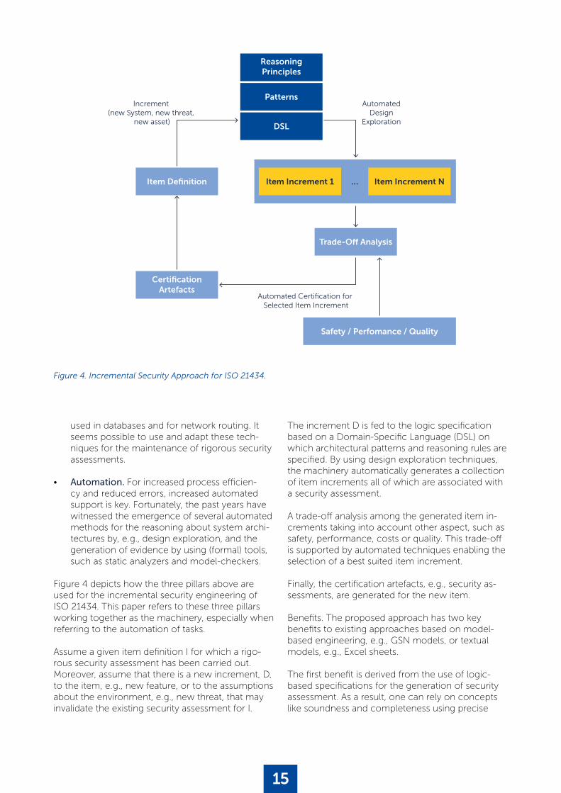
Figure 4 depicts how the three pillars above are used for the incremental security engineering of ISO 21434. This paper refers to these three pillars working together as the machinery, especially when referring to the automation of tasks.
Assume a given item definition I for which a rigo-rous security assessment has been carried out. Moreover, assume that there is a new increment, D, to the item, e. g., new feature, or to the assumptions about the environment, e. g., new threat, that may invalidate the existing security assessment for I.
The increment D is fed to the logic specification based on a Domain-Specific Language (DSL) on which architectural patterns and reasoning rules are specified. By using design exploration techniques, the machinery automatically generates a collection of item increments all of which are associated with a security assessment.
A trade-off analysis among the generated item in-crements taking into account other aspect, such as safety, performance, costs or quality. This trade-off is supported by automated techniques enabling the selection of a best suited item increment.
Finally, the certification artefacts, e. g., security as-sessments, are generated for the new item.
Benefits. The proposed approach has two key bene fits to existing approaches based on model- based engineering, e. g., GSN models, or textual models, e. g., Excel sheets.
The first benefit is derived from the use of logic- based specifications for the generation of security assessment. As a result, one can rely on concepts like soundness and completeness using precise
Increment (new System, new threat,
new asset)
AutomatedDesign
Exploration
Automated Certification for Selected Item Increment
ReasoningPrinciples
Patterns
DSL
Item Definition Item Increment 1 … Item Increment N
Trade-O� Analysis
Safety / Perfomance / Quality
Certification Artefacts
Figure 4. Incremental Security Approach for ISO 21434.
16
semantics, instead of the textual semantics which may be ambiguous in GSN models for example. This enables the automatic checking of whether the argument used in security assessments is correct or whether there are flaws in the reasoning or missing assumptions. Moreover, using logic-based tools, it is even possible to automatically enumerate which evidence is still required for completing a security argument.
The second benefit is provided by the use of incre-mental methods and automation. This enables a less human error prone and efficient certification process. Without these two elements, the overhead costs for certification is very high as already ob-served in the avionics domain where the change of a single line of code can imply costs of in the order of millions of USD.
A key impact of the two benefits above is that the proposed incremental approach enables continu-ous certification of connected vehicles. Whenever there is a new incremental change to the item or to the environment assumptions, new certification artefacts should be produced for certification. The use of rigorous security assessments and the incre-mental approach enable the production of these artefacts in a highly automated fashion by relying on automated reasoning tools, such as logic pro-gramming tools [25, 16]. Moreover, certification authorities have to check whether the artefacts are compliant to the ISO 21434. Since the methods used in the approach are based on rigorous security assessments, certification authorities can use exis-ting tools to automatically check whether the secu-rity arguments are correct.
Approach by ExampleThe goal of this section is to describe (1) how the proposed approach can be used to automate parts of the ISO 21434 risk assessment and (2) how this approach deals with incremental changes in the system architecture, thus supporting continuous security assessment and certification. To this end, the machinery is applied to the headlamp system explained in Section 2.
Automating ISO 21434
The machinery takes as input the preliminary sys-tem architecture as well as the damage scenarios associated with both assets from the system archi-tecture and cyber-security properties. The machine-ry also expects as input the impact rating for each given damage scenario. These artefacts cover three activities from the risk assessment, namely item de-finition, asset identification, and impact rating.8
Consider the Example 3.2 from Section 3. The as-set is the CAN bus transmitting messages from the Gateway ECU to the headlamp system. This section considers the Damage Scenario 1 only, namely un-expected loss of head light.
Example 5.1
In the DSL, one can specify both the identified asset and damage scenarios as follows:
asset(can2). dmgScenario(“hl turns off overnight driving”,can2,int, [maj,neg,maj,neg]).
The argument can2 denotes a Controller Area Net-work (CAN) used to communicate between ECUs. The fact asset(can2) denotes that can2 is an asset. The fact dmgScenario denotes a damage scenario (headlamp turns off overnight driving) associated with can2 and cyber-security property int (short for integrity). Following the impact rating given in Table 1, the impact rating for this scenario is specified as [maj,neg,maj,neg] (maj and neg are short for major and negligible, respectively).
Note that this example omits how the system archi-tecture is specified in the DSL. The interested rea-
8 Since these three activities are specific to the product being developed, they cannot be automated in general.
17
der can find detailed description on how to specify elements for the system architecture such as chan-nels and components in [17].
The next activities are the threat scenario identifi-cation and attack path analysis. The machinery can automate these activities. The reasoning principles specify a potential threat for each asset associated with a damage scenario. A potential threat becomes an actual threat if the asset may be reached by an attacker. The machinery expects as input the public elements of the system architecture, i.e., the elements that may be accessible by external users. Bluetooth and Cellular interfaces and OBD-II connector are considered to be public elements. Reachability rules are specified to automatically check whether from a public element (e. g., Blue-tooth) an attacker may access an asset (e. g., CAN bus) through a path P. The machinery identified three possible paths to access the CAN bus (located between Gateway ECU and headlamp system) from the public elements.
Next in the risk assessment are the attack feasibility rating and risk determination. As shown in Table 2, a level (e. g., high) is assigned to each step of an attacker’s path. The machinery takes as input the assigned level to each attack step of a given attack
path. It then automatically calculates the overall level of an attack path following the attack potential approach. Given the overall level of an attack path, reasoning principles rules are specified to automati-cally calculate the risk determination for each threat following the risk matrix method.
Example 5.2
The machinery outputs the following w.r.t. the attack feasibility rating and risk determination.
{attFS([can2,[can2,gw,can1,bt], int, maj],high)} {riskDT([can2,[can2,gw,can1,bt], int,maj],4)}
For both facts, attFS and riskDT, the first argument is the threat ID. The threat ID is composed of the identified asset (can2), the attacker’s path (direction from right to left), the cyber-security property (in-tegrity), and the impact rating (major). This example considers the safety impact rating only. The last argument of attFS and riskDT denotes, respectively, the overall feasibility rating (high), and the risk value for the identified threat (4).
Navigation ECU
FIREWALL
Cellular Bluetooth
Gateway ECU
Other ECUs
CameraECU
HeadlampSwitch
Headlamp System
Lamp LowON / HiON / OFFRequest
Oncoming Car InformationYes / No
ITEM BOUNDARY
HEADLAMP SYSTEM(Functional)
OBD-IIConnector
PowerSwitch
Actuator
Body ControlECU
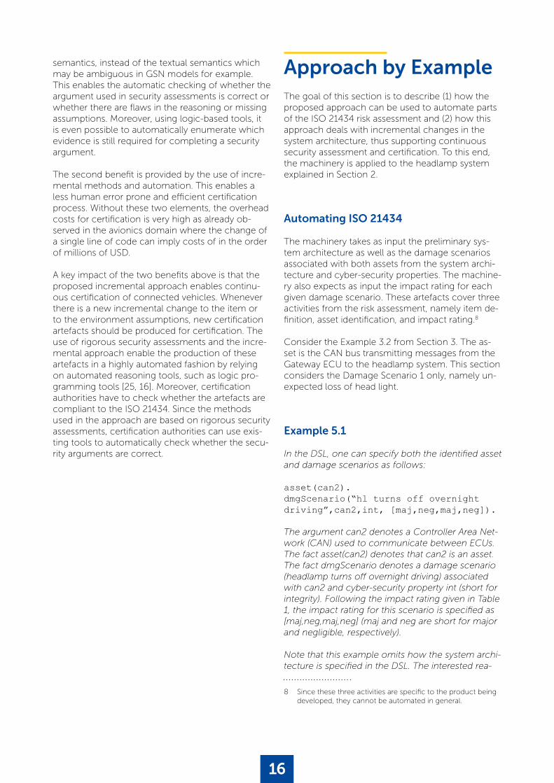
Figure 5. Headlamp system with a Firewall
18
The last activity in the risk assessment is risk treat-ment decision. The machinery enables the auto-mated recommendation of security patterns to mitigate identified threats. To this end, reasoning principles are specified for (1) Mitigation: which threats can be mitigated by a given deployed secu-rity pattern and which threats cannot be mitigated. (2) Security Pattern Recommendation: which security patterns, e. g., Firewall or Security Monitor, can be used and where exactly they should be de-ployed to mitigate threats that have not yet been mitigated.
The machinery recommended using a firewall to mitigate the identified threat. The architecture of the headlamp system with a firewall is depicted in Figure 5. A firewall is deployed between the Gate-way ECU and the headlamp system. The goal is to mitigate malicious incoming flows from public elements such as Bluetooth, Cellular or OBD-II connector.
In summary, the machinery can automate the follo-wing parts of the ISO 21434 risk assessment:
identification of threats given damage scenarios (threat scenario identification)
identification of the attacker’s path to exploit identified threats (attack path analysis)
calculation of the overall level of an attacker’s path (attack feasibility rating) given the assig-ned level to each attack step of an attack path
calculation of the risk value for each identified threat (risk determination)
recommendation of security patterns to mit-igate identified threats (risk treatment decision), explicitly suggesting where to deploy them in the architecture
Incremental Security Approach
To illustrate the incremental approach depicted in Figure 4, assume that there is an incremental change in the headlamp system as follows.
Increment. Consider as increment the ability to per-form software updates on the Body Control ECU. It is assumed that at some point during the life-cycle of the headlamp system a software update on the Body Control ECU is performed. This software up-date may be performed by, e. g., a wired connection through the OBD-II connector, or through-the-air by using the Bluetooth or Cellular interfaces.
The considered increment may lead to new threats to the headlamp system as new flows are genera-ted between public elements (e. g., OBD-II connec-tor) and the headlamp system. A potential threat is an attacker injecting malicious code into the Body Control ECU (asset) in an unauthorized fashion. This potential threat may lead to loss of integrity of the Body Control ECU due to unauthorized access.
Following the approach illustrated in Figure 4, the machinery takes the inputs described in Section 5.1 and a potential threat to the Body Control ECU. The machinery then automatically checks whether the given potential threat is an actual threat by checking possible attacker’s paths. Three attacker’s paths are identified, initiated from the OBD-II connector, Blue-tooth and Cellular interface, respectively.
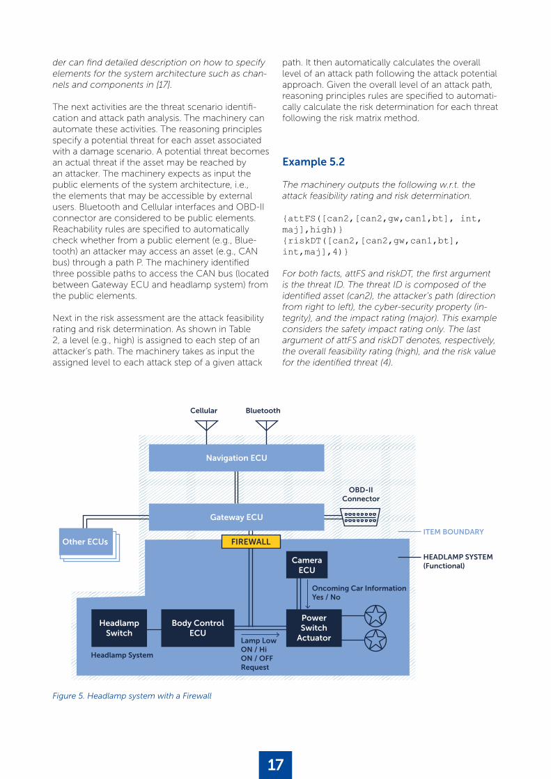
Figure 6. Headlamp system with a Firewall and a Security Monitor
Navigation ECU
FIREWALL
Sec. Monitor
Cellular Bluetooth
Gateway ECU
Other ECUs
CameraECU
HeadlampSwitch
Headlamp System
Lamp LowON / HiON / OFFRequest
Oncoming Car InformationYes / No
ITEM BOUNDARY
HEADLAMP SYSTEM(Functional)
OBD-IIConnector
PowerSwitch
Actuator
Body ControlECU
Navigation ECU
FIREWALL
Sec. Monitor
Cellular Bluetooth
Gateway ECU
Other ECUs
CameraECU
HeadlampSwitch
Headlamp System
Lamp LowON / HiON / OFFRequest
Oncoming Car InformationYes / No
OBD-IIConnector
PowerSwitch
Actuator
Body ControlECU
(a) Sec. monitor associated to the Body Control ECU (b) Sec. monitor associated to the CAN bus
19
Automated Design Exploration. Next, the machi-nery automatically suggests solutions for mitigating the identified threat. Two solutions are depicted in Figure 6. It suggested the deployment of a security monitor to mitigate the identified threat. The goal is to mitigate malicious access from public elements by enforcing access control policies, such as “only authorized users from public elements may write data into the Body Control ECU”.
Figure 6a illustrates a security monitor associated with the Body Control ECU, whereas Figure 6b illustrates a security monitor associated with the CAN bus. Both solutions can mitigate the identified threat. The main difference is that the former may be deployed by means of software instrumentation, and the latter may be deployed as a physical proxy between the Gateway ECU and the Body Control ECU.
Trade-off Analysis. A trade-off analysis should be carried out to help engineers to choose the best suited solution for the system. For example, the se-curity monitor deployed as a proxy might be more
expensive (performance-wise) than the one deploy-ed by means of software instrumentation. The reason is that the deployed proxy shall intercept each incoming message from the Gateway ECU regardless of the destination of the message. The security monitor associated with the Body Control ECU shall only intercept messages destined to the Body Control ECU itself. Hence, based on the performance impact of such solutions, one may choose the security monitor illustrated in Figure 6a over the one illustrated in Figure 6b.
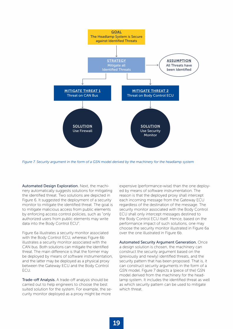
Automated Security Argument Generation. Once a design solution is chosen, the machinery can construct the security argument based on the (previously and newly) identified threats, and the security pattern that has been proposed. That is, it can construct security arguments in the form of a GSN model. Figure 7 depicts a (piece of the) GSN model derived from the machinery for the head-lamp system. It includes the identified threat as well as which security pattern can be used to mitigate which threat.
GOALThe Headlamp System is Secure
against Identified Threats
STRATEGYMitigate all
Identified Threats
MITIGATE THREAT 1Threat on CAN Bus
MITIGATE THREAT 2Threat on Body Control ECU
SOLUTIONUse Firewall
SOLUTIONUse Security
Monitor
ASSUMPTIONAll Threats have been Identified
Figure 7. Security argument in the form of a GSN model derived by the machinery for the headlamp system

20
21
Related WorkRecent white papers [12][32] also give an overview on ISO 21434. They both discuss the set of guide-lines proposed for securing automotive vehicles. The white paper [12] focuses on the activities per-formed in the risk assessment. It proposes an ap-proach to automotive cybersecurity engineering. This approach suggests the use of offense and de-fense mechanisms for helping engineers to imple-ment the guidelines of ISO 21434. The white paper [32] proposes a layered approach for securing auto-motive vehicles. The advantage of this approach is to reduce the probability of an attack’s success by providing multi-layered response to attacks for protection, detection, and response. This paper pro-poses an incremental approach to enable the conti-nuous certification for automotive vehicles.
ThreatGet is a model-based engineering tool for security analysis [30][5]. ThreatGet can perform se-curity analysis on system architectures following the ISO 21434 risk assessment. ThreatGet automatically identifies threats given a path between a source and a target element. ThreatGet lists possible counter-measure that can be selected by users to mitigate the identified threats. The main advantages of the machinery presented here over ThreatGet include that it can automate more parts of the ISO 21434 risk assessment such as both attack feasibility rating and risk determination. It explicitly shows where countermeasures shall be deployed in the system architecture to mitigate identified threats. It enables the construction of security arguments in the form of a GSN model. To the best of our knowledge, ThreatGet does not support the generation of such security arguments. Finally, this paper considers an incremental approach to risk assessment, thus ena-bling continuous certification.
Goal-oriented approaches, such as GSN [6] and KAOS [20], have been used for modeling safety cases. Similar to these approaches, several papers [13] have proposed using Attack Trees [31] for modeling risk assessments. Extensions include quantitative models for evaluating how defenses can be used to mitigate attacks [13, 15]. A key difference to the approach proposed here is the focus on automa-ted analysis. Whereas in the previous work, Attack Defense trees shall be manually constructed, the proposed approach can carry out such analysis in an automated fashion.
A number of work [29, 21, 24] have proposed using general models encompassing both safety and
security concerns. For example, GSN extensions with security features, so that in a single frame-work, one can express both security and safety [24]. More over, our previous work [23, 27] proposed me-chanisms for extracting security relevant informa-tion from safety analysis, such as Fault Tree Analysis or Failure Mode and Effects Analysis.
While this paper is inspired by these previous work, the main focus here is on incremental methods for safety and security co-analysis. As illustrated by the running example and in our previous work [18], the proposed approach takes into account both safety and security during trade-offs to determine the best design increments.
22
Next Research DirectionsThe vision of this project is to build an incremental safety and security co-analysis with patterns. The aim is to develop an incremental process for system safety and security assurance cases using automa-ted methods that incorporate both safety and secu-rity reasoning principles.
Some promising steps towards this vision have been made. Safety reasoning principles have been proposed in [17]. Security reasoning principles with patterns have been partially presented in this white paper and in [18].
Some more research is needed to fully realize the vision. The next steps toward this vision include:
Make Assumptions Explicit. A safety case often contains implicit assumptions (e. g., decisions based on own experience), e. g., as-sumptions on channel independence or lack of side-channel attacks. Often no evidence is collected validating such implicit assumptions which may lead to implementation errors. The purpose is to make such assumptions more explicit, e. g., what are the assumptions needed for choosing a particular safety or se-curity pattern? The next step is to augment the reasoning principles rules [17][18] with explicit assumptions to enable a more precise analysis w.r.t., e. g., pattern selection.
Improve the trade-off analysis. Safety and security co-analysis may lead to interrelations. There can be conflicts, synergies or no con-flicts between safety and security. For exam-ple, implementing a firewall needed for secu-rity reasons might lead to new faults (safety) as the firewall might incorrectly blocks messages from the system. Upon finding out the trade-offs, safety and security engineers will possibly decide what actions to take to solve conflicts or synergies. Engineers shall take into account aspects, e. g., performance or safety, to reach a consensus w.r.t. solutions for the system. The next step here is to investigate directions on how to integrate such aspects into the trade-off analysis in a (semi-) automated fashion. As a result, one can provide a more holistic trade-off analysis with multiple aspects that can assist engineers to decide the best design solution for the system.
Tooling. Currently, the machinery is based on the logic programming engine DLV [25] for automating safety and security reasoning principles such as pattern recommendation. As mentioned earlier, performance is one of the aspects to be integrated into the trade-off analysis. To this end, reasoning principles with timing may be specified so that one can analyze possible trade-offs regarding the run-time overhead caused by solutions. DLV might not be suitable for specifying such reasoning principles with timing. Moreover, reasoning principles on the probability of faults occurren-ce may be specified to enable a more precise analysis w.r.t. pattern selection. The next step is to investigate what tools can be used to spe-cify such reasoning principles. For example, one could combine DLV with SMT-solvers to enable the specification of reasoning principles with fault probabilities.
Integration into Model-Based Engineering Approaches. One can imagine the machinery (including DSL, patterns, and reasoning prin-ciples) as a backend for model-based engi-neering approaches. That is, it can be used as a process inside a model-based engineering tool to provide rigorous safety and security assessment to the given system architectures. There fore, the next step here is to integrate the machinery into the model-based engineering tool AutoFOCUS3 [1]. This integration leads to a number of benefits including (a) assisting engineers to operationalize the process of providing rigorous assessment to system archi-tecture, and (b) improving the usability of the machinery by providing a user-friendly graphi-cal interface tool for engineers.

23
ConclusionThis paper describes the ISO 21434 standard for automotive security focusing on the activities and artefacts that shall be produced by engineers. The paper goes beyond the ISO 21434 by describing an incremental security engineering approach. It illustrates by example how this approach can sup-port engineers in constructing arguments for item security claims. Finally, it points to multiple research directions to realize the proposed incremental ap-proach in an operational setting.
The ISO 21434 is a step forward towards increasing vehicle security as it addresses some of the key challenges upcoming with the increased adoption
of ICT in vehicles. However, without adequate automated methods, it may fall short given the tight deadlines in placing vehicles in the market. This pressure may cause engineers to cut corners by overlooking (implicit) assumptions or not taking into account the trade-offs between safety and security thus leading to insecure vehicles.
Therefore, the next years will require a co-joint ef-fort between research institutes, industry and certi-fication bodies to develop the framework needed, i.e., methods and processes, to efficiently derive appropriate security arguments supported by com-prehensive evidence.
24
References[1] AF3 – AutoFOCUS 3. More information at https: //af3.fortiss.org/.
[2] ISO 26262, Road vehicles – Functional safety — Part 6: Product development: software level. Available from https://www.iso.org/standard/ 43464.html.
[3] ISO/SAE AWI 21434, Road Vehicles – Cyber-security engineering. Under development.
[4] SAE – Society of Automotive Engineers, SAE J3061 - Cybersecurity Guidebook for Cyber-Phy-sical Automotive Systems. Available from https://www.sae.org/standards/content/j3061_201601/.
[5] Threatget – threat analysis and risk manage-ment. Available at https://www.threatget.com/.
[6] GSN Community Standard Version 1. 2011. Available at http://www.goalstructuringnotation. info/documents/GSN_Standard.pdf.
[7] Hackers remotely kill a Jeep on the high-way – with me in it, 2015. Available at https://www.wired.com/2015/07/hackersremotely-kill-jeep- highway/.
[8] Q1 2019 sees a rapid growth of automotive cyber incidents, 2019. Available at https://upstream.auto/blog/q1-2019-sees-a-rapid-growth-of- automotivecyber- incidents/.
[9] The changing face of automotive cyber attacks, 2020. Available at https://www.trustonic.com/opinion/the-changing-face-ofautomotive- cyber-attacks/.
[10] Cyber attacks on automotive sector picking up speed, 2020. Available at https://www.hornetsecurity.com/en/securityinfor-mation/cyber-attacks-onautomotive-sector-picking-up-speed/.
[11] Upstream security’s 2020 global automotive cybersecurity report, 2020. https://upstream.auto/upstreamsecurity-global-automotive-cybersecurity-report-2020/.
[12] Dr. Hasan I. Akram. Bridging the Cyberse-curity Gap in Automotive: The Upcoming ISO/SAE 21434 and its Implications for Automotive Cyber-security Engineering. Matrickz GmbH, White Paper, 2020.
[13] Alessandra Bagnato, Barbara Kordy, Per Håkon Meland, and Patrick Schweitzer. Attribute decoration of attack-defense trees. IJSSE, 3(2):1–35, 2012.
[14] Tewodros A. Beyene and Harald Ruess. Evidential and continuous integration of software verification tools. In Formal Methods – 22nd Inter-national Symposium, FM 2018, Held as Part of the Federated Logic Conference, FloC 2018, Oxford, UK, July 15-17, 2018, Proceedings, pages 679–685, 2018.
[15] Stefano Bistarelli, Fabio Fioravanti, and Pa-mela Peretti. Defense tree for economic evaluations of security investment. In ARES 06, pages 416–423, 2006.
[16] Simon Cruanes, Grégoire Hamon, Sam Owre, and Natarajan Shankar. Tool Integration with the Evidential Tool Bus. In Verification, Model Checking, and Abstract Interpretation, 14th International Con-ference, VMCAI. Proceedings, 2013.
[17] Yuri Gil Dantas, Antoaneta Kondeva, and Vivek Nigam. Less manual work for safety engi-neers: Towards an automated safety reasoning with safety patterns. In International Conference on Logic Programming (ICLP), 2020.
[18] Yuri Gil Dantas, Antoaneta Kondeva, and Vivek Nigam. Towards automating safety and security co-analysis with patterns (position paper). In Safecomp, 2020.
[19] Yuri Gil Dantas, Vivek Nigam, and Carolyn Talcott. A formal security assessment framework for cooperative adaptive cruise control. In IEEE Vehicu-lar Networking Conference (VNC), 2020.
[20] Anne Dardenne, Axel van Lamsweerde, and Stephen Fickas. Goal-directed requirements acquisi-tion. Sci. Comput. Program., 20(1-2):3–50, 1993.
[21] Edward Griffor, editor. Handbook of System Safety and Security. 2016.
[22] Ashish Gupta, Inderpal Singh Mumick, and V. S. Subrahmanian. Maintaining views incremen-tally. In Peter Buneman and Sushil Jajodia, editors, Proceedings of the 1993 ACM SIGMOD Internatio-nal Conference on Management of Data, Washing-ton, DC, USA, May 26–28, 1993, pages 157–166. ACM Press, 1993.
25
[23] Antoaneta Kondeva, Carmen Carlan, Harald Ruess, and Vivek Nigam. On computer-aided tech-niques for supporting safety and security co-engi-neering. In The 9th IEEE International Workshop on Software Certification WoSoCer, 2019.
[24] Per Håkon Meland, Elda Paja, Erlend Andreas Gjære, Stephane Paul, Fabiano Dalpiaz, and Paolo Giorgini. Threat analysis in goal-oriented security requirements modelling. Int. J. Secur. Softw. Eng., 5(2):1–19, 2014.
[25] Wolfgang Faber Thomas Eiter Georg Gott-lob Simona Perri Francesco Scarcello Nicola Leone, Gerald Pfeifer. The dlv system for knowledge re-presentation and reasoning. ACM Trans. Comput. Logic, 7:499–562, 2006.
[26] Vivek Nigam, Limin Jia, Boon Thau Loo, and Andre Scedrov. Maintaining distributed logic programs incrementally. Computer Languages, Systems & Structures, 38(2):158–180, 2012.
[27] Vivek Nigam, Alexander Pretschner, and Harald Ruess. Model-based safety and security engi-neering. White Paper, 2018.
[28] Vivek Nigam and Carolyn L. Talcott. Formal security verification of industry 4.0 applications. In 24th IEEE International Conference on Emerging Technologies and Factory Automation, ETFA 2019, Zaragoza, Spain, September 10-13, 2019, pages 1043–1050, 2019.
[29] Nicola Nostro, Andrea Bondavalli, and Nuno Silva. Adding security concerns to safety critical certification. In Symposium on Software Reliability Engineering Workshops, 2014.
[30] Magdy El Sadany, Christoph Schmittner, and Wolfgang Kastner. Assuring compliance with protection profiles with threatget. In Alexander B. Romanovsky, Elena Troubitsyna, Ilir Gashi, Erwin Schoitsch, and Friedemann Bitsch, editors, Com-puter Safety, Reliability, and Security - SAFECOMP 2019 Workshops, ASSURE, DECSoS, SASSUR, STRIVE, and WAISE, Turku, Finland, September 10, 2019, Proceedings, volume 11699 of Lecture Notes in Computer Science, pages 62–73. Springer, 2019.
[31] B. Schneier. Attack trees: Modeling secu-rity threats. Dr. Dobb’s Journal of Software Tools, 24:21–29, 1999.
[32] Vit Sembera. ISO/SAE 21434: Setting the Standard for Connected Cars’ Cybersecurity. Trend Micro Research, White Paper, 2020.
[33] Adam Shostack. Threat Modeling: Designing for Security. Wiley.
[34] Abraao Aires Urquiza, Musab A. AlTurki, Max I. Kanovich, Tajana Ban Kirigin, Vivek Nigam, Andre Scedrov, and Carolyn L. Talcott. Resource-bounded intruders in denial of service attacks. In 32nd IEEE Computer Security Foundations Symposium, CSF 2019, Hoboken, NJ, USA, June 25-28, 2019, pages 382–396, 2019.
26
Publisherfortisswww.fortiss.org© 2021
AuthorsYuri Gil DantasDr. Vivek NigamDr. Harald Ruess
LayoutSonja Taut
Printviaprinto | CEWE Stiftung & Co. KGaAMartin-Luther-King-Weg 30a48155 Münster
ISSN Print ISSN Online2699-1217 2700-2977
1. Edition, April 2021
Picture CreditsTitle: shutterstock ©TierneyMJPage 4: shutterstock © metamorworksPage 6: shutterstock © Titima Ongkantong Page 14: shutterstock © Wright Studio Page 20: shutterstock © LevLev Page 23: shutterstock © Iurii MotovSeite 26: fortissGmbH © Kathrin Kahle
Imprint
27
Although this white paper was prepared with the utmost care and diligence, inaccuracies cannot be excluded. No guarantee is provided, and no legal responsibility or liability is assumed for any damages resulting from erroneous information.
fortiss is the Free State of Bavaria research institute for software-intense systems based in Munich. The institute’s scientists work on research, development and transfer projects together with universities and technology companies in Bavaria and other parts of Germany, as well across Europe. The research activities focus on state-of-the-art methods, tech-niques and tools used in software development and systems & service engineering and their application with cognitive cyber-physical systems such as the Internet of Things (IoT). fortiss is legally structured as a non-profit limited liability company (GmbH). The shareholders are the Free State of Bavaria (majority shareholder) and the Fraunhofer-Gesellschaft zur Förderung der ange-wandten Forschung e.V.

28
fortiss GmbHGuerickestraße 2580805 MunichGermanywww.fortiss.orgTel.: +49 89 3603522 0E-Mail: [email protected]