for internal use - iwow · 4.10 subscriber identity module (sim) interface - simio, simclk, simrst,...
TRANSCRIPT

CONFIDENTIAL
TR-900C Module
Product Technical Specifications and Design Notes
Date : 1 August 2014
Document Version : 1.7
Our Reference : 02000B36
Confidential
TR-900C Module Product Technical Specification • 02000B36v1.6
i
All specifications are correct at the time of release. iWOW Connections owns the proprietary rights to the information contained herein this document. It may not be edited, copied or circulated without prior written agreement by iWOW Connections Pte Ltd. © 2011, 2012 iWOW Connections Pte Ltd.
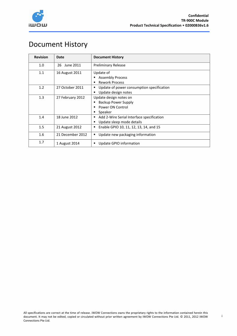
Document History
Revision Date Document History
1.0 26 June 2011 Preliminary Release
1.1 16 August 2011 Update of Assembly Process Rework Process
1.2 27 October 2011 Update of power consumption specification Update design notes
1.3 27 February 2012 Update design notes on Backup Power Supply Power ON Control Speaker
1.4 18 June 2012 Add 2-Wire Serial Interface specification Update sleep mode details
1.5 21 August 2012 Enable GPIO 10, 11, 12, 13, 14, and 15
1.6 21 December 2012 Update new packaging information
1.7 1 August 2014 Update GPIO information

Confidential
TR-900C Module Product Technical Specification • 02000B36v1.6
ii
All specifications are correct at the time of release. iWOW Connections owns the proprietary rights to the information contained herein this document. It may not be edited, copied or circulated without prior written agreement by iWOW Connections Pte Ltd. © 2011, 2012 iWOW Connections Pte Ltd.
GENERAL NOTE
This document aims to support the application and engineering efforts of iWOW’s customers. This document is
intended for testing, evaluation, integration, and information purposes only.
iWOW makes every effort to ensure that the quality of the information. However, the content of this
documentation is provided on an “as is” basis and may contain deficiencies or inadequacies.
iWOW disclaims any warranty and all responsibility for the application of the device(s) that is made in relation
to the accuracy, reliability or contents of this document. iWOW is not liable for any injury, loss or damage of
any kind that may incur from the use or reliance of this document.
iWOW reserves the right to make any modifications, additions and deletions to this document due to
typographical errors, inaccurate information, or improvement to our products at any time without notice.

Confidential
TR-900C Module Product Technical Specification • 02000B36v1.6
iii
All specifications are correct at the time of release. iWOW Connections owns the proprietary rights to the information contained herein this document. It may not be edited, copied or circulated without prior written agreement by iWOW Connections Pte Ltd. © 2011, 2012 iWOW Connections Pte Ltd.
TABLE OF CONTENTS
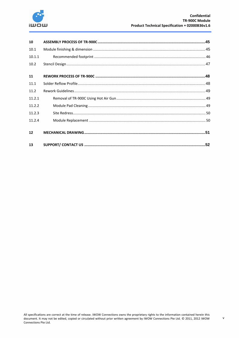
1 INTRODUCTION ............................................................................................................................ 1
1.1 Reference Documents ................................................................................................................... 1
1.2 Abbreviations ............................................................................................................................... 1
1.3 Safety Precautions ........................................................................................................................ 3
2 TECHNICAL SPECIFICATIONS ......................................................................................................... 5
2.1 General Specifications ................................................................................................................... 5
2.2 GSM/ GPRS Specifications ............................................................................................................. 5
2.3 RF Frequencies ............................................................................................................................. 6
2.4 Baseband Functionalities ............................................................................................................... 6
2.5 Interface Specifications ................................................................................................................. 7
3 FUNCTIONAL ARCHITECTURE ........................................................................................................ 8
4 INTERFACES ................................................................................................................................. 9
4.1 Castellation Connections ............................................................................................................... 9
4.1.1 TR-900C Pin-Out description......................................................................................................... 10
4.2 Power Supply and Ground – VBAT, GND ....................................................................................... 11
4.3 Operating Modes ........................................................................................................................ 12
4.3.1 Power Specs .................................................................................................................................. 13
4.4 Backup Power Supply – VBACKUP ................................................................................................ 14
4.4.1 Application .................................................................................................................................... 14
4.5 Analog to Digital Converter (ADC) – ADCIN1 ................................................................................. 15
4.6 Power ON Control - PWON .......................................................................................................... 15
4.6.1 Auto Switch-ON ............................................................................................................................ 16
4.6.2 Manual Switch ON ........................................................................................................................ 16
4.6.3 Switch-OFF Condition ................................................................................................................... 16
4.7 Signal for RF Burst Indication, RF_IND .......................................................................................... 17
4.8 Reset Signal - RESET .................................................................................................................... 18
4.9 Digital Supply Output - VRIO ........................................................................................................ 19
4.10 Subscriber Identity Module (SIM) Interface - SIMIO, SIMCLK, SIMRST, VRSIM .................................. 20
4.11 Serial Link (UART) Interfaces ........................................................................................................ 21
4.11.1 Modem port - TX, RX, CTS, RTS, RI, DCD, DTR, DSR ...................................................................... 21
4.12 Application ................................................................................................................................. 22
4.12.1 Ring Indicate - RI ........................................................................................................................... 23

Confidential
TR-900C Module Product Technical Specification • 02000B36v1.6
iv
All specifications are correct at the time of release. iWOW Connections owns the proprietary rights to the information contained herein this document. It may not be edited, copied or circulated without prior written agreement by iWOW Connections Pte Ltd. © 2011, 2012 iWOW Connections Pte Ltd.
4.13 USB Interface – VBUS, USB_DM, USB_DP ..................................................................................... 24
4.13.1 Application .................................................................................................................................... 24
4.14 Analog Audio Interfaces – MICN, MICP, SPKNA, SPKPA .................................................................. 25
4.14.1 Microphone input – MICN, MICP .................................................................................................. 25
4.14.2 MIC Application ............................................................................................................................ 25
4.14.3 Speaker – SPKNA, SPKPA .............................................................................................................. 26
4.14.4 Application .................................................................................................................................... 27
4.15 LED Pulse Generator – LPG .......................................................................................................... 27
4.16 General Purposes Input / Output ports – GPIO .............................................................................. 29
4.17 Serial Peripheral Interface (SPI) – SPI_CLK, SPI_MISO, SPI_MOSI, SPI_NCS0, SPI_IRQ ....................... 30
4.17.1 SPI Address 0................................................................................................................................. 30
4.17.2 SPI Interrupt .................................................................................................................................. 30
4.18 2-Wire Serial Interface – I2C_SDA, I2C_SCL ................................................................................... 31
4.19 RF interface ................................................................................................................................ 31
4.19.1 General RF Guide .......................................................................................................................... 32
4.19.2 RF Performance ............................................................................................................................ 33
4.19.3 Recommendations ........................................................................................................................ 33
5 ELECTRICAL & RELIABILITY CHARACTERISTICS .............................................................................. 34
5.1 Electrical Characteristics .............................................................................................................. 34
5.2 Absolute Maximum Ratings ......................................................................................................... 35
5.3 Reliability Compliance ................................................................................................................. 36
6 GENERAL RECOMMENDATION .................................................................................................... 37
6.1 General Layout Guideline ............................................................................................................ 37
6.2 Firmware Upgrade ...................................................................................................................... 38
6.3 Power Supply Guideline .............................................................................................................. 38
7 INCOMING INSPECTION CRITERIA FOR TR-900C MODULE ............................................................. 40
7.1 Logistics Inspection ..................................................................................................................... 41
8 STORAGE CONDITIONS ............................................................................................................... 41
9 PACKAGING INFORMATION ........................................................................................................ 42
9.1 ESD Tray..................................................................................................................................... 42
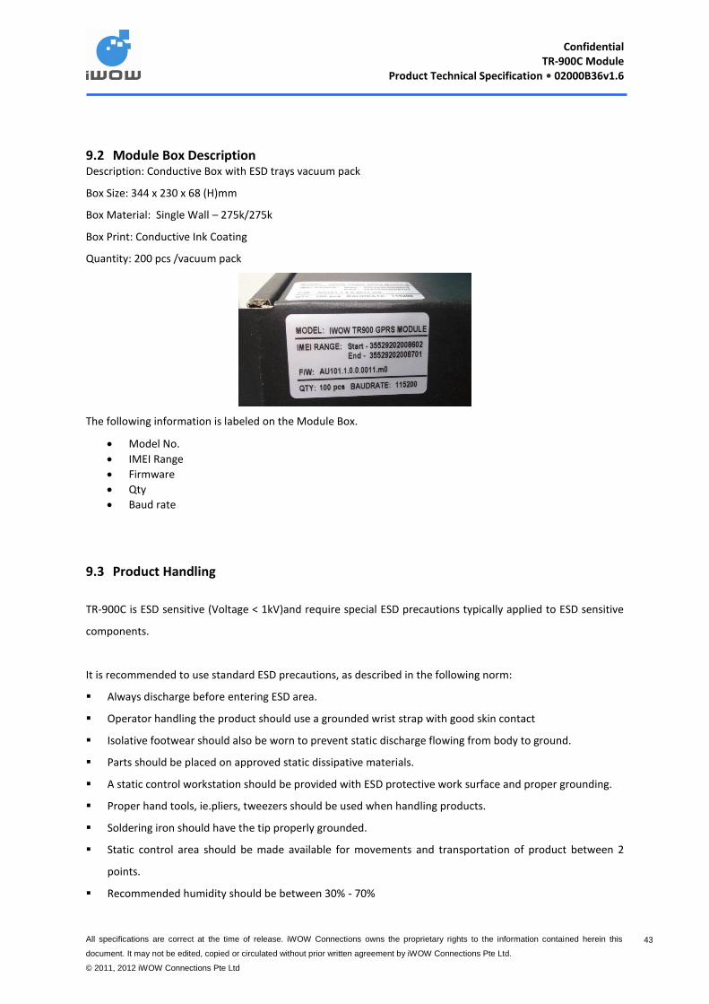
9.2 Module Box Description .............................................................................................................. 43
9.3 Product Handling ........................................................................................................................ 43
9.4 Moisture Sensitivity .................................................................................................................... 44
Confidential
TR-900C Module Product Technical Specification • 02000B36v1.6
v
All specifications are correct at the time of release. iWOW Connections owns the proprietary rights to the information contained herein this document. It may not be edited, copied or circulated without prior written agreement by iWOW Connections Pte Ltd. © 2011, 2012 iWOW Connections Pte Ltd.
10 ASSEMBLY PROCESS OF TR-900C ................................................................................................. 45
10.1 Module finishing & dimension ..................................................................................................... 45
10.1.1 Recommended footprint .............................................................................................................. 46
10.2 Stencil Design ............................................................................................................................. 47
11 REWORK PROCESS OF TR-900C ................................................................................................... 48
11.1 Solder Reflow Profile ................................................................................................................... 48
11.2 Rework Guidelines ...................................................................................................................... 49
11.2.1 Removal of TR-900C Using Hot Air Gun ........................................................................................ 49
11.2.2 Module Pad Cleaning .................................................................................................................... 49
11.2.3 Site Redress................................................................................................................................... 50
11.2.4 Module Replacement ................................................................................................................... 50
12 MECHANICAL DRAWING ............................................................................................................. 51
13 SUPPORT/ CONTACT US ............................................................................................................. 52
Confidential
TR-900C Module Product Technical Specification • 02000B36v1.6
All specifications are correct at the time of release. iWOW Connections owns the proprietary rights to the information contained herein this
document. It may not be edited, copied or circulated without prior written agreement by iWOW Connections Pte Ltd.
© 2011, 2012 iWOW Connections Pte Ltd
1 1
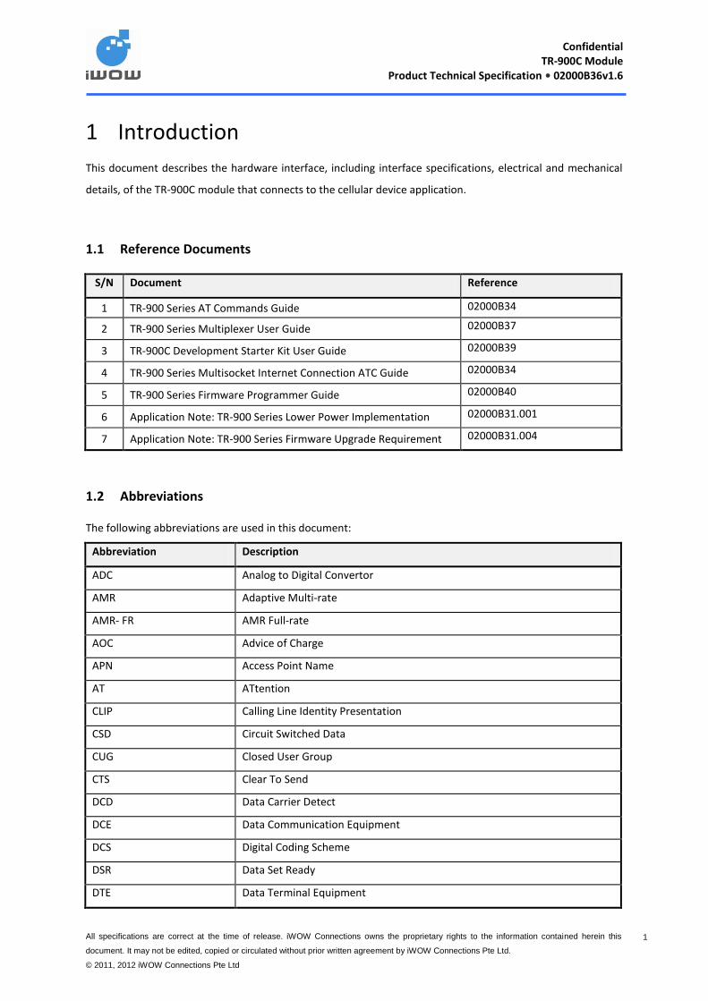
1 Introduction
This document describes the hardware interface, including interface specifications, electrical and mechanical
details, of the TR-900C module that connects to the cellular device application.
1.1 Reference Documents
S/N Document Reference
1 TR-900 Series AT Commands Guide 02000B34
2 TR-900 Series Multiplexer User Guide 02000B37
3 TR-900C Development Starter Kit User Guide 02000B39
4 TR-900 Series Multisocket Internet Connection ATC Guide 02000B34
5 TR-900 Series Firmware Programmer Guide 02000B40
6 Application Note: TR-900 Series Lower Power Implementation 02000B31.001
7 Application Note: TR-900 Series Firmware Upgrade Requirement 02000B31.004
1.2 Abbreviations
The following abbreviations are used in this document:
Abbreviation Description
ADC Analog to Digital Convertor
AMR Adaptive Multi-rate
AMR- FR AMR Full-rate
AOC Advice of Charge
APN Access Point Name
AT ATtention
CLIP Calling Line Identity Presentation
CSD Circuit Switched Data
CUG Closed User Group
CTS Clear To Send
DCD Data Carrier Detect
DCE Data Communication Equipment
DCS Digital Coding Scheme
DSR Data Set Ready
DTE Data Terminal Equipment
Confidential
TR-900C Module Product Technical Specification • 02000B36v1.6
All specifications are correct at the time of release. iWOW Connections owns the proprietary rights to the information contained herein this
document. It may not be edited, copied or circulated without prior written agreement by iWOW Connections Pte Ltd.
© 2011, 2012 iWOW Connections Pte Ltd
2 2
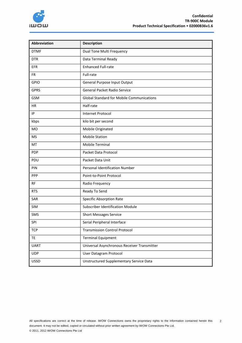
Abbreviation Description
DTMF Dual Tone Multi Frequency
DTR Data Terminal Ready
EFR Enhanced Full-rate
FR Full-rate
GPIO General Purpose Input Output
GPRS General Packet Radio Service
GSM Global Standard for Mobile Communications
HR Half-rate
IP Internet Protocol
kbps kilo bit per second
MO Mobile Originated
MS Mobile Station
MT Mobile Terminal
PDP Packet Data Protocol
PDU Packet Data Unit
PIN Personal Identification Number
PPP Point-to-Point Protocol
RF Radio Frequency
RTS Ready To Send
SAR Specific Absorption Rate
SIM Subscriber Identification Module
SMS Short Messages Service
SPI Serial Peripheral Interface
TCP Transmission Control Protocol
TE Terminal Equipment
UART Universal Asynchronous Receiver Transmitter
UDP User Datagram Protocol
USSD Unstructured Supplementary Service Data
Confidential
TR-900C Module Product Technical Specification • 02000B36v1.6
All specifications are correct at the time of release. iWOW Connections owns the proprietary rights to the information contained herein this
document. It may not be edited, copied or circulated without prior written agreement by iWOW Connections Pte Ltd.
© 2011, 2012 iWOW Connections Pte Ltd
3 3
1.3 Safety Precautions
For your own safety, please follow the safety precautions listed below during all phases of the operation,
usage, service or repair of any cellular terminal or mobile incorporating the TR-900C GSM/GPRS Module. All
manufacturers of these cellular terminals or mobile devices are advised to include the following safety
precautions into all manuals provided with their terminal or mobile device, and pass this information to device
users and operating personnel. Failure to comply may be dangerous or illegal.
Road safety
Do not use a mobile device while driving. Park the vehicle first or use a hand free earphone. It is illegal in some
countries to use a mobile device while driving.
Switch off in aircraft
Cellular terminal or mobile devices can cause interference to aircraft electronics. Using them on aircraft is both
illegal and dangerous.
Switch off when refuelling vehicle
Do not use the cellular terminal or mobile device at a refuelling station or near fuels or chemicals.
Forbidden Usage
Always switch off your cellular terminal or mobile device where it is forbidden to be used in any areas like a
hospital.
Interference
All cellular terminals or mobile devices may be subjected to radio interference, which could affect their
performance.
Emergency calls
As the GPRS/GSM module is based on GSM standard for radio signals and cellular networks, this connection
cannot be guaranteed at all times under all conditions. It should never be entirely relied upon for essential
communications such as an emergency call.
Note on compliance with international rules and regulations
The TR-900C module is a fully certified GSM/GPRS engine. The module has been tested and certified for
compliance to international safety and GSM standard requirements at the modular level.
Confidential
TR-900C Module Product Technical Specification • 02000B36v1.6
All specifications are correct at the time of release. iWOW Connections owns the proprietary rights to the information contained herein this
document. It may not be edited, copied or circulated without prior written agreement by iWOW Connections Pte Ltd.
© 2011, 2012 iWOW Connections Pte Ltd
4 4
Manufacturers of cellular terminal or mobile equipment incorporating the TR-900C are advised to test their
final products to ensure compliance to these EMC tests/requirements:
ESD
Radiated Spurious Emissions
Conducted Emissions, if applicable
Further tests if applicable
Manufacturers of the final products are also responsible to ensure that their products are tested for
compliance to any other regulatory requirements that might be applicable.

Confidential
TR-900C Module Product Technical Specification • 02000B36v1.6
All specifications are correct at the time of release. iWOW Connections owns the proprietary rights to the information contained herein this
document. It may not be edited, copied or circulated without prior written agreement by iWOW Connections Pte Ltd.
© 2011, 2012 iWOW Connections Pte Ltd
5 5
2 Technical Specifications
2.1 General Specifications
Feature Description
Network Type Quad-Band GSM/GPRS
Frequency Bands Quad Band: GSM850 / EGSM900 / DCS1800 / PCS1900
Output Power GSM 850 / EGSM 900 : Class 4 (2W)
DCS1800 / PCS1900: Class 1 (1W)
AT Command Interface Compliant to GSM 07.05 and GSM 07.07 recommendations
iWOW Proprietary AT Commands
Physical Dimensions Dimensions: 27 x 27 x 3mm
Weight: 4g
Power Supply 3.2V to 4.5V
Operational Environmental Description
Normal Operating Temperature
-20° C to +55° C
Extended Operating Temperature
-40° C to +85° C
Relative humidity 5 – 95%
Air pressure (altitude) 70 kPa to 106 kPa (-400m to 3000m)
2.2 GSM/ GPRS Specifications
Feature Description
GSM Audio Telephony
Emergency call
Half Rate, Full Rate and Enhanced Full Rate (HR/FR/EFR)
Adaptive Multi-rate (AMR)
Hands-Free Operation
Echo Cancellation (Enhanced AEC)
Noise Reduction
DTMF Encoding
Circuit Switched Data (CSD) Asynchronous, Transparent & Non-Transparent
Max speed: up to 14.4kbps
Confidential
TR-900C Module Product Technical Specification • 02000B36v1.6
All specifications are correct at the time of release. iWOW Connections owns the proprietary rights to the information contained herein this
document. It may not be edited, copied or circulated without prior written agreement by iWOW Connections Pte Ltd.
© 2011, 2012 iWOW Connections Pte Ltd
6 6
Feature Description
SMS Point-to-point (MO/MT)
Cell Broadcast
Text and PDU mode
Supplementary Services Call Forwarding, Barring, Waiting, Hold
Multiparty
Advice of Charge (AoC)
Calling Line Identification Restriction (CLIR)
Unstructured Supplementary Services (USSD)
Closed User Group (CUG)
GPRS Multislot Class 12
Mobile Station Class B
Coding Schemes CS1 – CS4
PBCCH Support
PCCCH Support
PPP Stack
EDGE-RX Multislot Class 12 (downlink)
Coding Schemes RX MCS1 – MCS9, TX MCS1 – MCS4
DARP SAIC Support
2.3 RF Frequencies
RF functionalities comply with the GSM Phase II GSM 850/EGSM 900/DCS 1800/PCS 1900 recommendations. The frequencies covered are:
Tx GSM850: (824 ~ 849 MHz)
Tx EGSM900: (880 ~ 915 MHz)
Tx DCS1800: (1710 ~ 1785 MHz)
Tx PCS1900: (1850 ~ 1910 MHz)
Rx GSM850: (869 ~ 894 MHz)
Rx EGSM900: (925 ~ 960 MHz)
Rx DCS1800: (1805 ~ 1880 MHz)
Rx PCS1900: (1930 ~ 1990 MHz)
2.4 Baseband Functionalities
The Baseband is composed of an ARM, a DSP and an analog element (with audio signals, and ADC). The core power supply for signal interface is 1.8V.
Confidential
TR-900C Module Product Technical Specification • 02000B36v1.6
All specifications are correct at the time of release. iWOW Connections owns the proprietary rights to the information contained herein this
document. It may not be edited, copied or circulated without prior written agreement by iWOW Connections Pte Ltd.
© 2011, 2012 iWOW Connections Pte Ltd
7 7
2.5 Interface Specifications
TR-900C module has a 50-pin castellation form factor which provides the following interface:
Power Supply
1 Serial Link UART
USB
1.8V/3V SIM
GPIOs
Analog to Digital Converter
Reset
Power On
SPI with 2 Addresses*
2-Wire Bus*
Antenna Pad
RF indicator
* For hardware reference only. These features are not enabled in the standard module firmware as it requires a
certain level of firmware customization depending on its intended application. Please contact iWOW for more
information.
Confidential
TR-900C Module Product Technical Specification • 02000B36v1.6
All specifications are correct at the time of release. iWOW Connections owns the proprietary rights to the information contained herein this
document. It may not be edited, copied or circulated without prior written agreement by iWOW Connections Pte Ltd.
© 2011, 2012 iWOW Connections Pte Ltd
8 8
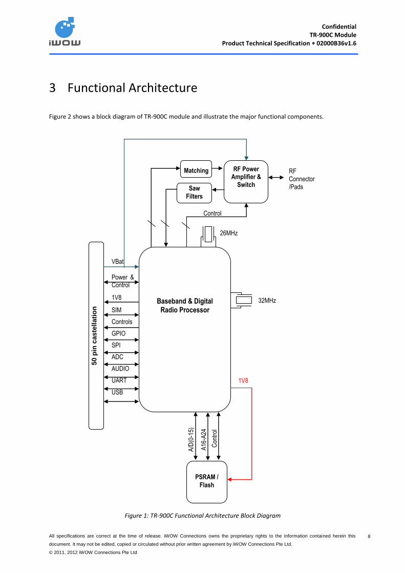
3 Functional Architecture
Figure 2 shows a block diagram of TR-900C module and illustrate the major functional components.
Figure 1: TR-900C Functional Architecture Block Diagram
26MHz
50 p
in c
aste
lla
tio
n
VBat Power & Control
1V8
SIM
Controls
GPIO
SPI
ADC
AUDIO
UART
USB
Baseband & Digital
Radio Processor
PSRAM /
Flash
A/D
(0-1
5)
A16
-A24
Con
trol
1V8
32MHz
Matching
Saw
Filters
RF Power Amplifier &
Switch
RF Connector /Pads
Control

Confidential
TR-900C Module Product Technical Specification • 02000B36v1.6
All specifications are correct at the time of release. iWOW Connections owns the proprietary rights to the information contained herein this
document. It may not be edited, copied or circulated without prior written agreement by iWOW Connections Pte Ltd.
© 2011, 2012 iWOW Connections Pte Ltd
9 9
4 INTERFACES
This section describes the available interfaces and their characteristics. All Pin Voltage are supplying at nominal
1.8V unless specified otherwise.
4.1 Castellation Connections
TR-900C module has a 50-pin castellation form factor.
Figure 2: TR-900C Pin Assignments
50
49
48
47
46
45
44
43
42
41
40
39
38
37
36
35
34
33
32
31
30
29
28
27
26
24
23
22
21
20
19
18
17
16
15
14
13
12
11
10
9
8
7
6
5
4
3
2
1
Pin 1
25
GND
GPIO5
GPIO4
(LPG) GND
VBAT
VBAT
GPIO12/SPI_MISO
GPIO15/SPI_MOSI
GPIO10/SPI_CLK
GPIO11/SPI_NCS0
SPI-IRQ
I2C_SDA
I2C_SCL
GN
D
SIM
-RS
T
SIM
-IO
SIM
-CLK
VR
SIM
GP
IO9
GP
IO8
MIC
N
MIC
P
SP
KN
SP
KP
GN
D
GND
VBACKUP
VRIO
ADCIN1
NC
NC
PWON
USB_DM
USB_DP
VBUS
SYS_RES
ET
GPIO3
GND
UA
RT
_T
X
UA
RT
_R
X
GN
D
AN
T
GN
D
RF
_IN
D
GP
IO14_C
TS
GP
IO13_R
TS
GP
IO1_D
SR
GP
IO7_D
CD
GP
IO6_D
TR
GP
IO2_R
I
Confidential
TR-900C Module Product Technical Specification • 02000B36v1.6
All specifications are correct at the time of release. iWOW Connections owns the proprietary rights to the information contained herein this
document. It may not be edited, copied or circulated without prior written agreement by iWOW Connections Pte Ltd.
© 2011, 2012 iWOW Connections Pte Ltd
10 10
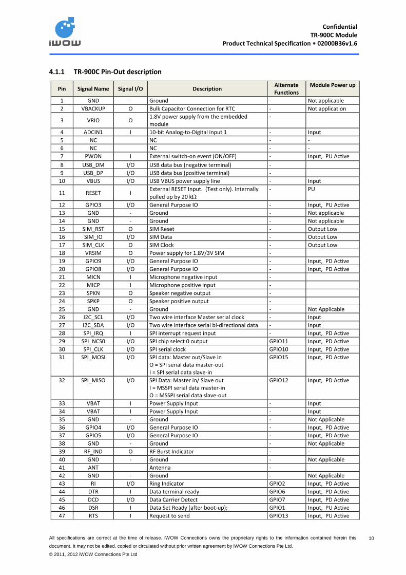
4.1.1 TR-900C Pin-Out description
Pin Signal Name Signal I/O Description Alternate Functions
Module Power up
1 GND - Ground - Not applicable
2 VBACKUP O Bulk Capacitor Connection for RTC - Not application
3 VRIO O 1.8V power supply from the embedded module
-
4 ADCIN1 I 10-bit Analog-to-Digital input 1 - Input
5 NC NC - -
6 NC NC - -
7 PWON I External switch-on event (ON/OFF) - Input, PU Active
8 USB_DM I/O USB data bus (negative terminal) -
9 USB_DP I/O USB data bus (positive terminal) -
10 VBUS I/O USB VBUS power supply line - Input
11 RESET I External RESET Input. (Test only). Internally
pulled up by 20 k
- PU
12 GPIO3 I/O General Purpose IO - Input, PU Active
13 GND - Ground - Not applicable
14 GND - Ground - Not applicable
15 SIM_RST O SIM Reset - Output Low
16 SIM_IO I/O SIM Data - Output Low
17 SIM_CLK O SIM Clock - Output Low
18 VRSIM O Power supply for 1.8V/3V SIM -
19 GPIO9 I/O General Purpose IO - Input, PD Active
20 GPIO8 I/O General Purpose IO - Input, PD Active
21 MICN I Microphone negative input -
22 MICP I Microphone positive input -
23 SPKN O Speaker negative output -
24 SPKP O Speaker positive output -
25 GND - Ground - Not Applicable
26 I2C_SCL I/O Two wire interface Master serial clock - Input
27 I2C_SDA I/O Two wire interface serial bi-directional data - Input
28 SPI_IRQ I SPI interrupt request input - Input, PD Active
29 SPI_NCS0 I/O SPI chip select 0 output GPIO11 Input, PD Active
30 SPI_CLK I/O SPI serial clock GPIO10 Input, PD Active
31 SPI_MOSI I/O SPI data: Master out/Slave in O = SPI serial data master-out I = SPI serial data slave-in
GPIO15 Input, PD Active
32 SPI_MISO I/O SPI Data: Master in/ Slave out I = MSSPI serial data master-in O = MSSPI serial data slave-out
GPIO12 Input, PD Active
33 VBAT I Power Supply Input - Input
34 VBAT I Power Supply Input - Input
35 GND - Ground - Not Applicable
36 GPIO4 I/O General Purpose IO - Input, PD Active
37 GPIO5 I/O General Purpose IO - Input, PD Active
38 GND - Ground - Not Applicable
39 RF_IND O RF Burst Indicator - -
40 GND - Ground - Not Applicable
41 ANT Antenna -
42 GND - Ground - Not Applicable
43 RI I/O Ring Indicator GPIO2 Input, PD Active
44 DTR I Data terminal ready GPIO6 Input, PD Active
45 DCD I/O Data Carrier Detect GPIO7 Input, PD Active
46 DSR I Data Set Ready (after boot-up); GPIO1 Input, PU Active
47 RTS I Request to send GPIO13 Input, PU Active
Confidential
TR-900C Module Product Technical Specification • 02000B36v1.6
All specifications are correct at the time of release. iWOW Connections owns the proprietary rights to the information contained herein this
document. It may not be edited, copied or circulated without prior written agreement by iWOW Connections Pte Ltd.
© 2011, 2012 iWOW Connections Pte Ltd
11 11
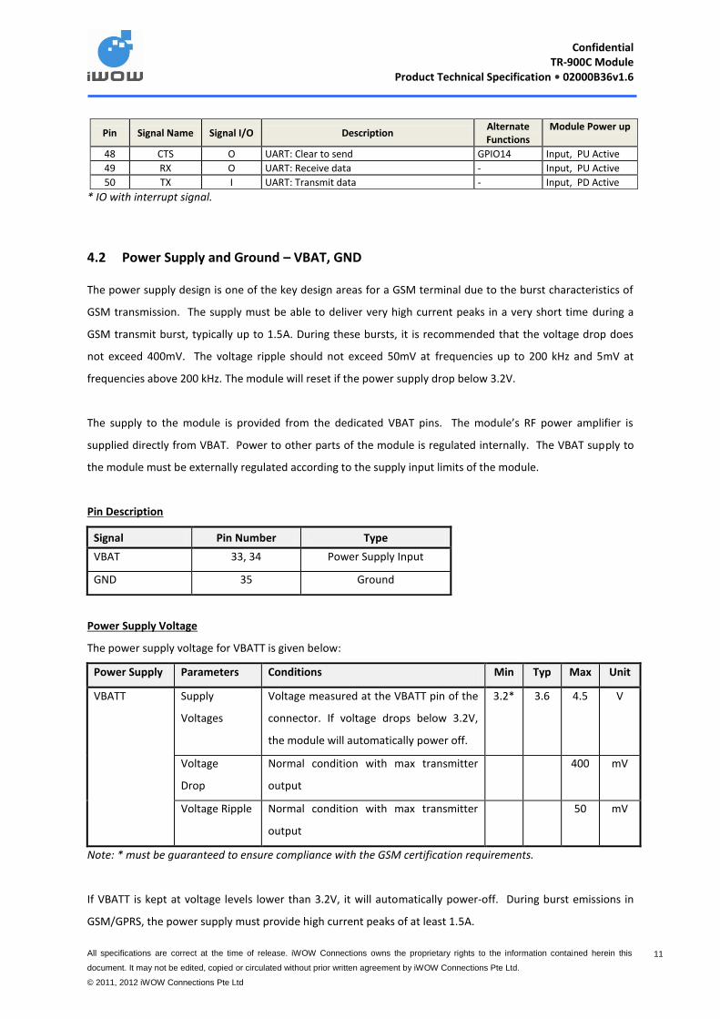
Pin Signal Name Signal I/O Description Alternate Functions
Module Power up
48 CTS O UART: Clear to send GPIO14 Input, PU Active
49 RX O UART: Receive data - Input, PU Active
50 TX I UART: Transmit data - Input, PD Active
* IO with interrupt signal.
4.2 Power Supply and Ground – VBAT, GND
The power supply design is one of the key design areas for a GSM terminal due to the burst characteristics of
GSM transmission. The supply must be able to deliver very high current peaks in a very short time during a
GSM transmit burst, typically up to 1.5A. During these bursts, it is recommended that the voltage drop does
not exceed 400mV. The voltage ripple should not exceed 50mV at frequencies up to 200 kHz and 5mV at
frequencies above 200 kHz. The module will reset if the power supply drop below 3.2V.
The supply to the module is provided from the dedicated VBAT pins. The module’s RF power amplifier is
supplied directly from VBAT. Power to other parts of the module is regulated internally. The VBAT supply to
the module must be externally regulated according to the supply input limits of the module.
Pin Description
Power Supply Voltage
The power supply voltage for VBATT is given below:
Power Supply Parameters Conditions Min Typ Max Unit
VBATT Supply
Voltages
Voltage measured at the VBATT pin of the
connector. If voltage drops below 3.2V,
the module will automatically power off.
3.2* 3.6 4.5 V
Voltage
Drop
Normal condition with max transmitter
output
400 mV
Voltage Ripple Normal condition with max transmitter
output
50 mV
Note: * must be guaranteed to ensure compliance with the GSM certification requirements.
If VBATT is kept at voltage levels lower than 3.2V, it will automatically power-off. During burst emissions in
GSM/GPRS, the power supply must provide high current peaks of at least 1.5A.
Signal Pin Number Type
VBAT 33, 34 Power Supply Input
GND 35 Ground
Confidential
TR-900C Module Product Technical Specification • 02000B36v1.6
All specifications are correct at the time of release. iWOW Connections owns the proprietary rights to the information contained herein this
document. It may not be edited, copied or circulated without prior written agreement by iWOW Connections Pte Ltd.
© 2011, 2012 iWOW Connections Pte Ltd
12 12
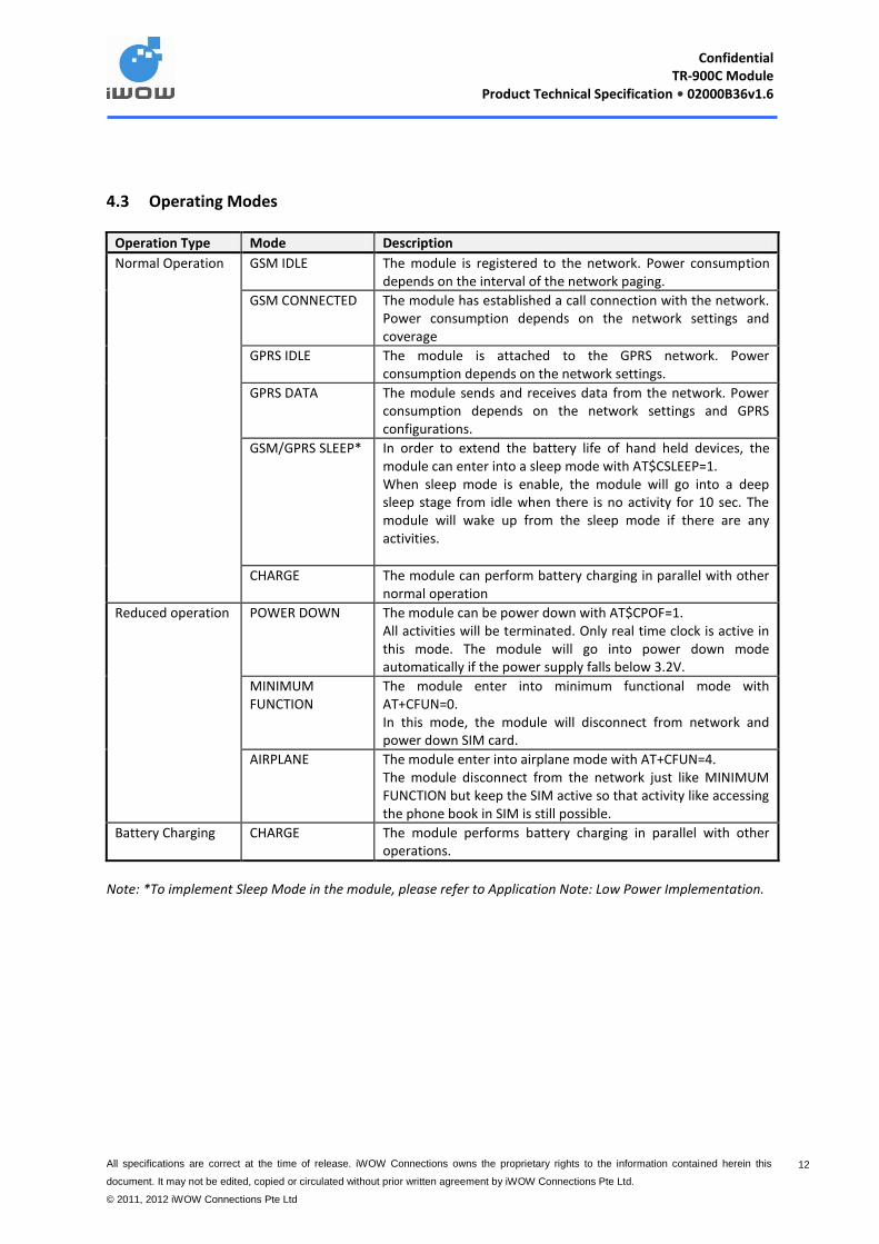
4.3 Operating Modes
Operation Type Mode Description
Normal Operation GSM IDLE The module is registered to the network. Power consumption depends on the interval of the network paging.
GSM CONNECTED The module has established a call connection with the network. Power consumption depends on the network settings and coverage
GPRS IDLE The module is attached to the GPRS network. Power consumption depends on the network settings.
GPRS DATA The module sends and receives data from the network. Power consumption depends on the network settings and GPRS configurations.
GSM/GPRS SLEEP* In order to extend the battery life of hand held devices, the module can enter into a sleep mode with AT$CSLEEP=1. When sleep mode is enable, the module will go into a deep sleep stage from idle when there is no activity for 10 sec. The module will wake up from the sleep mode if there are any activities.
CHARGE The module can perform battery charging in parallel with other normal operation
Reduced operation POWER DOWN The module can be power down with AT$CPOF=1. All activities will be terminated. Only real time clock is active in this mode. The module will go into power down mode automatically if the power supply falls below 3.2V.
MINIMUM FUNCTION
The module enter into minimum functional mode with AT+CFUN=0. In this mode, the module will disconnect from network and power down SIM card.
AIRPLANE The module enter into airplane mode with AT+CFUN=4. The module disconnect from the network just like MINIMUM FUNCTION but keep the SIM active so that activity like accessing the phone book in SIM is still possible.
Battery Charging CHARGE The module performs battery charging in parallel with other operations.
Note: *To implement Sleep Mode in the module, please refer to Application Note: Low Power Implementation.

Confidential
TR-900C Module Product Technical Specification • 02000B36v1.6
All specifications are correct at the time of release. iWOW Connections owns the proprietary rights to the information contained herein this
document. It may not be edited, copied or circulated without prior written agreement by iWOW Connections Pte Ltd.
© 2011, 2012 iWOW Connections Pte Ltd
13 13
4.3.1 Power Specs
Operating Mode Conditions Average Burst Unit
Power Down VBATT = 3.6V 34 - µA
Minimum Function VBATT = 3.6V 36 - uA
Airplane Mode VBATT = 3.6V 36 - uA
GSM/GPRS Idle DRX = 2 21 - mA
DRX = 9 20 - mA
GSM/GPRS Sleep DRX = 2 2.1 - mA
DRX = 9 1.2 - mA
GSM Connected GSM 850, EGSM 900, PCL = 5 199 1270 mA
GSM 850, EGSM 900, PCL = 19 58 145 mA
DCS 1800, PCS 1900, PCL = 0 149 864 mA
DCS 1800, PCS 1900, PCL = 15 57 120 mA
GPRS Data GSM 850, EGSM 900, PCL = 5, Class 8 187 1271 mA
GSM 850, EGSM 900, PCL = 5, Class 10 211 886 mA
DCS 1800, PCS 1900, PCL = 0, Class 8 141 915 mA
DCS 1800, PCS 1900, PCL = 0, Class 10 232 890 mA
Confidential
TR-900C Module Product Technical Specification • 02000B36v1.6
All specifications are correct at the time of release. iWOW Connections owns the proprietary rights to the information contained herein this
document. It may not be edited, copied or circulated without prior written agreement by iWOW Connections Pte Ltd.
© 2011, 2012 iWOW Connections Pte Ltd
14 14
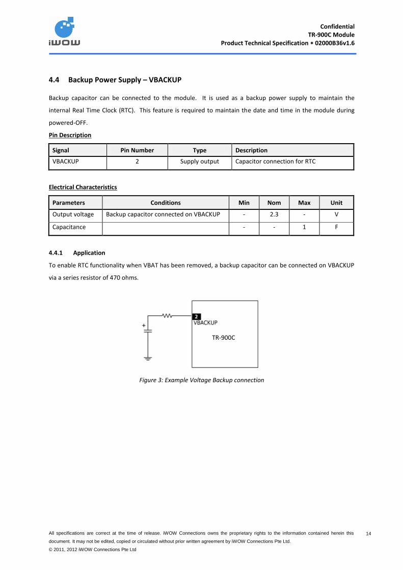
4.4 Backup Power Supply – VBACKUP
Backup capacitor can be connected to the module. It is used as a backup power supply to maintain the
internal Real Time Clock (RTC). This feature is required to maintain the date and time in the module during
powered-OFF.
Pin Description
Signal Pin Number Type Description
VBACKUP 2 Supply output Capacitor connection for RTC
Electrical Characteristics
Parameters Conditions Min Nom Max Unit
Output voltage Backup capacitor connected on VBACKUP - 2.3 - V
Capacitance - - 1 F
4.4.1 Application
To enable RTC functionality when VBAT has been removed, a backup capacitor can be connected on VBACKUP
via a series resistor of 470 ohms.
Figure 3: Example Voltage Backup connection
TR-900C
Confidential
TR-900C Module Product Technical Specification • 02000B36v1.6
All specifications are correct at the time of release. iWOW Connections owns the proprietary rights to the information contained herein this
document. It may not be edited, copied or circulated without prior written agreement by iWOW Connections Pte Ltd.
© 2011, 2012 iWOW Connections Pte Ltd
15 15
4.5 Analog to Digital Converter (ADC) – ADCIN1
The module provides a 10-bit ADC inputs, ADCIN1.
Note: Connect ADCIN1 to GND if not in use.
Pin Description
Signal Pin Number Type Description
ADCIN1 4 Analog Input ADC input 1
Electrical Characteristics
Parameters Conditions Min Nom Max Unit
Resolution - - 10 - Bits
Reference voltage - - 1.2 - V
Differential non-linearity - -2 - 2 LSB
Integral non-linearity Best Fitting -2 - 2 LSB
Input Range - 0 1.2 V
Input Resistance - 1 - MΩ
For hardware reference only. This feature is not enabled in the standard module firmware as it requires a
certain level of firmware customization depending on its intended application. Please contact iWOW for more
information.
4.6 Power ON Control - PWON
This input pin is used to switch the module ON. A switch-ON interruption is triggered in the module at the
detection of a rising edge of this signal pin over a period of 30ms.
Note: The module should be properly switched OFF before all power supplies are removed. This is to avoid any
corruption of internal data.
Pin Description
Electrical Characteristics
Parameters Min Nom Max Unit
High level input voltage, VIH 1.495 - - V
Low level input voltage, VIL - - 0.805 V
Signal Pin Number Type Description
PWON 7 Input External switch-on event

Confidential
TR-900C Module Product Technical Specification • 02000B36v1.6
All specifications are correct at the time of release. iWOW Connections owns the proprietary rights to the information contained herein this
document. It may not be edited, copied or circulated without prior written agreement by iWOW Connections Pte Ltd.
© 2011, 2012 iWOW Connections Pte Ltd
16 16
4.6.1 Auto Switch-ON
The module will be switch on automatically when the power is applied if the auto power on feature is enable.
4.6.2 Manual Switch ON
The module can be switch on manually when the auto power on feature is disabled. Please contact iWOW if
this feature is required.
This condition will switch-ON the module:
When the main supply is above 3.2V.
When a falling edge, after debouncing, is detected on the PWON pin. The PWON pin is debounced by
embedded hardware. The debouncing time is approximately 30ms.
4.6.3 Switch-OFF Condition
This condition will switch-OFF the module:
When AT+CPWROFF is sent to Modem.
A rising edge signal is detected on the PWON pin after debouncing and the signal remains high for a
minimum period of 900ms. The PWON signal must be released back to low after the module has
switched-OFF.
Note: When the switch-OFF sequence is started, the sequence is completed even if a switch-ON condition
occurs. In this event, data corruption may occur if flash writing is in progress.
PWON
Module
Switch On
~ 30 ms
Vbat
PWON
~900ms
Module
(Switch-off)

Confidential
TR-900C Module Product Technical Specification • 02000B36v1.6
All specifications are correct at the time of release. iWOW Connections owns the proprietary rights to the information contained herein this
document. It may not be edited, copied or circulated without prior written agreement by iWOW Connections Pte Ltd.
© 2011, 2012 iWOW Connections Pte Ltd
17 17
Figure 4. Example of the PWON Pin Connection either By a Switch or Via an NPN/PNP Transistors
4.7 Signal for RF Burst Indication, RF_IND
The RF_IND signal is a 2.8V indication signal for TX/RX Burst with a 100Kpull-up resistor.
Pin Description
Electrical Characteristics
Parameters Conditions Min Nom Max Unit
VOH - 2.2 - 2.65 V
VOL - - - 0.5 V
Tadvance - - 18 - µs
Tdelay - - 18 - µs
RF_IND Status
Signal Pin Number Type Description
RF_IND 39 Output RF Burst Indicator
Module State Status
During TX burst High
No TX activity Low
TR-900C TR-900C

Confidential
TR-900C Module Product Technical Specification • 02000B36v1.6
All specifications are correct at the time of release. iWOW Connections owns the proprietary rights to the information contained herein this
document. It may not be edited, copied or circulated without prior written agreement by iWOW Connections Pte Ltd.
© 2011, 2012 iWOW Connections Pte Ltd
18 18
Figure 5. RF_IND State During TX Burst
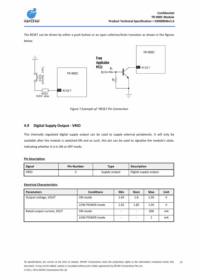
4.8 Reset Signal - RESET
This reset Pin 11 provides an unconditional hardware reset input to the module. A low level signal will trigger
the reset of the module. When the pin is not used, it can be left unconnected. This pin is internally pulled up
by a 20 k resistor to 1V8.
Figure 6. Reset Timing
Pin Description
Signal Pin Number Type Description
RESET 11 Input(internally pulled up by 20 k) External Reset Input.
Parameters Min Nom Max Unit Operating
Mode
High level input voltage, VIH 1.17 - - V Reset Inactive
Low level input voltage, VIL - - 0.63 V Reset Activated
Note: The hardware reset is to be used with caution. It may cause data loss in the volatile memory. It is
designed for emergency where the module fails to respond for more than 30 sec.
RF_IND
TIME SLOT
Tadvance Tdelay
VBATT
On/OFF
~RESET
250ms (min)
Ta
Confidential
TR-900C Module Product Technical Specification • 02000B36v1.6
All specifications are correct at the time of release. iWOW Connections owns the proprietary rights to the information contained herein this
document. It may not be edited, copied or circulated without prior written agreement by iWOW Connections Pte Ltd.
© 2011, 2012 iWOW Connections Pte Ltd
19 19
The RESET can be driven by either a push button or an open collector/drain transistor as shown in the figures
below.
Figure 7.Example of ~RESET Pin Connection
4.9 Digital Supply Output - VRIO
This internally regulated digital supply output can be used to supply external peripherals. It will only be
available after the module is switched-ON and as such, this pin can be used to signalize the module’s state,
indicating whether it is in ON or OFF mode.
Pin Description
Signal Pin Number Type Description
VRIO 3 Supply output Digital supply output
Electrical Characteristics
Parameters Conditions Min Nom Max Unit
Output voltage, VOUT ON mode 1.65 1.8 1.95 V
LOW POWER mode 1.65 1.85 1.95 V
Rated output current, IOUT ON mode - - 200 mA
LOW POWER mode - - 1 mA
TR-900C
TR-900C
Confidential
TR-900C Module Product Technical Specification • 02000B36v1.6
All specifications are correct at the time of release. iWOW Connections owns the proprietary rights to the information contained herein this
document. It may not be edited, copied or circulated without prior written agreement by iWOW Connections Pte Ltd.
© 2011, 2012 iWOW Connections Pte Ltd
20 20
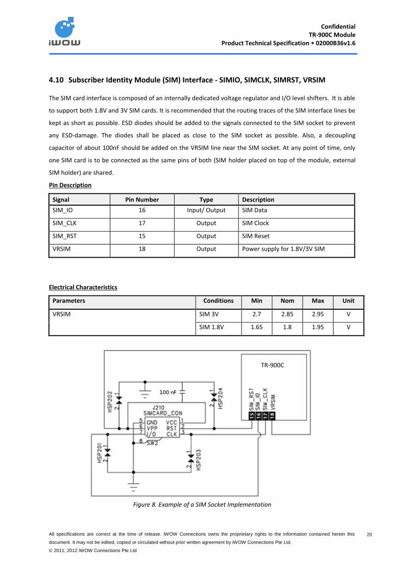
4.10 Subscriber Identity Module (SIM) Interface - SIMIO, SIMCLK, SIMRST, VRSIM
The SIM card interface is composed of an internally dedicated voltage regulator and I/O level shifters. It is able
to support both 1.8V and 3V SIM cards. It is recommended that the routing traces of the SIM interface lines be
kept as short as possible. ESD diodes should be added to the signals connected to the SIM socket to prevent
any ESD-damage. The diodes shall be placed as close to the SIM socket as possible. Also, a decoupling
capacitor of about 100nF should be added on the VRSIM line near the SIM socket. At any point of time, only
one SIM card is to be connected as the same pins of both (SIM holder placed on top of the module, external
SIM holder) are shared.
Pin Description
Signal Pin Number Type Description
SIM_IO 16 Input/ Output SIM Data
SIM_CLK 17 Output SIM Clock
SIM_RST 15 Output SIM Reset
VRSIM 18 Output Power supply for 1.8V/3V SIM
Electrical Characteristics
Parameters Conditions Min Nom Max Unit
VRSIM SIM 3V 2.7 2.85 2.95 V
SIM 1.8V 1.65 1.8 1.95 V
Figure 8. Example of a SIM Socket Implementation
TR-900C

Confidential
TR-900C Module Product Technical Specification • 02000B36v1.6
All specifications are correct at the time of release. iWOW Connections owns the proprietary rights to the information contained herein this
document. It may not be edited, copied or circulated without prior written agreement by iWOW Connections Pte Ltd.
© 2011, 2012 iWOW Connections Pte Ltd
21 21
4.11 Serial Link (UART) Interfaces
4.11.1 Modem port - TX, RX, CTS, RTS, RI, DCD, DTR, DSR
These interfaces are assigned to the module communication with the host device using AT Commands.
The UART features are:
16C750 compatibility
Baud rate from 300 bits/s up to 115200 bits/s with auto-bauding support feature
Note: Default factory setting baudrate is set at 115200, unless other specified.
Data bit: 5, 6, 7, or 8 bits
Parity bit: even, odd, none
Stop bit: 1, 1.5, 2 bit(s)
RTS/CTS Hardware flow control
Software flow control (XON/XOFF)
Pin Description
Signal Pin Number I/O I/O Type Reset State Description
UART_TX 50 Input 1V8 1 DCE Data Receive
UART_RX 49 Output 1V8 0 DCE Data Transmit
UART_CTS 48 Output 1V8 0 Clear To Send. Hardware flow
control
UART_RTS 47 Input 1V8 1 Ready To Send. Hardware flow
control
RI 43 Output 1V8 1 Ring Indicator
DCD 45 Output 1V8 1 Data Carrier Detect
DTR 44 Input 1V8 1 Data Terminal Ready
DSR 46 Output 1V8 1 Data Set Ready
Note:
If RTS and CTS are not in use, it is recommended to connect the pins together.
If DTR and DSR pins are not used, the pins are to be connected to GND.
10K pull up resistor to VIO is required for both TX and RTS pins.
Confidential
TR-900C Module Product Technical Specification • 02000B36v1.6
All specifications are correct at the time of release. iWOW Connections owns the proprietary rights to the information contained herein this
document. It may not be edited, copied or circulated without prior written agreement by iWOW Connections Pte Ltd.
© 2011, 2012 iWOW Connections Pte Ltd
22 22
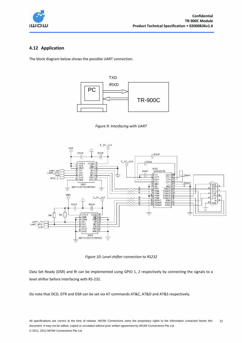
4.12 Application
The block diagram below shows the possible UART connection.
Figure 9: Interfacing with UART
Figure 10: Level-shifter connection to RS232
Data Set Ready (DSR) and RI can be implemented using GPIO 1, 2 respectively by connecting the signals to a
level shifter before interfacing with RS-232.
Do note that DCD, DTR and DSR can be set via AT-commands AT&C, AT&D and AT&S respectively.
TR-900C
TXD
/RXD
PC
Confidential
TR-900C Module Product Technical Specification • 02000B36v1.6
All specifications are correct at the time of release. iWOW Connections owns the proprietary rights to the information contained herein this
document. It may not be edited, copied or circulated without prior written agreement by iWOW Connections Pte Ltd.
© 2011, 2012 iWOW Connections Pte Ltd
23 23
4.12.1 Ring Indicate - RI
The Ring Indicator (RI) is used to indicate incoming call, unsolicited SMS and network activity indication.
For utilising power save mode in application design, it is recommended for customer to connect RI to an
interrupt line for their application. The application may be designed to receive an interrupt when RI goes low.
This signal is used as an interrupt to wake up the host application in the case where the sleep mode with
AT$CSLEEP=1 is activated when UART is turn off. This solution is best recommended for power consumption
sensitive application.
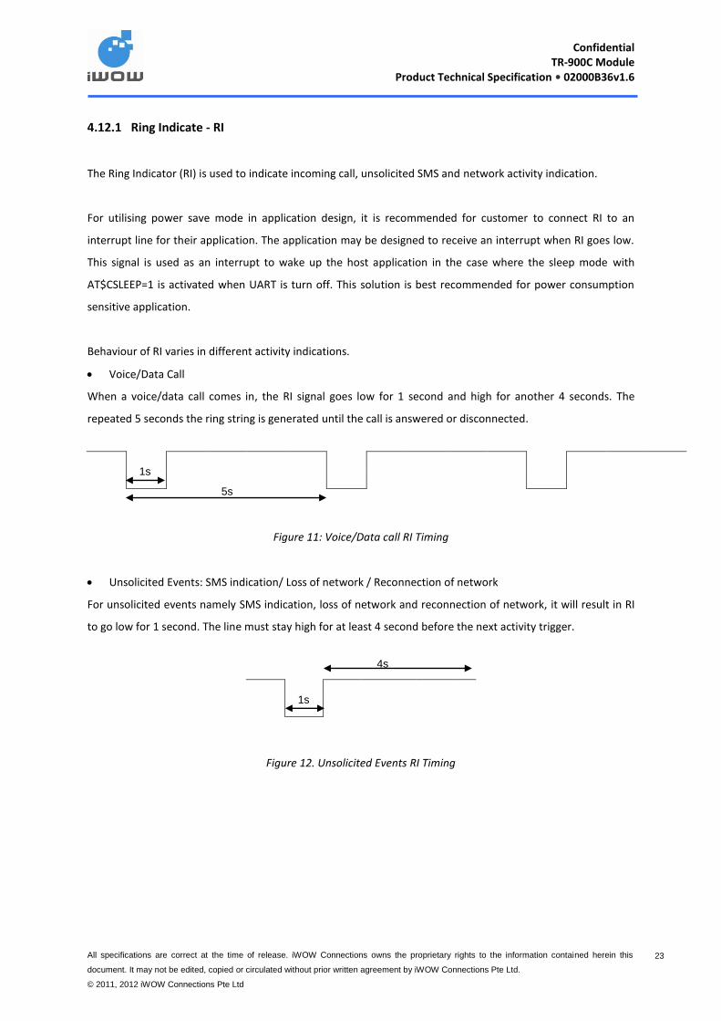
Behaviour of RI varies in different activity indications.
Voice/Data Call
When a voice/data call comes in, the RI signal goes low for 1 second and high for another 4 seconds. The
repeated 5 seconds the ring string is generated until the call is answered or disconnected.
Figure 11: Voice/Data call RI Timing
Unsolicited Events: SMS indication/ Loss of network / Reconnection of network
For unsolicited events namely SMS indication, loss of network and reconnection of network, it will result in RI
to go low for 1 second. The line must stay high for at least 4 second before the next activity trigger.
Figure 12. Unsolicited Events RI Timing
5s
1s
1s
4s

Confidential
TR-900C Module Product Technical Specification • 02000B36v1.6
All specifications are correct at the time of release. iWOW Connections owns the proprietary rights to the information contained herein this
document. It may not be edited, copied or circulated without prior written agreement by iWOW Connections Pte Ltd.
© 2011, 2012 iWOW Connections Pte Ltd
24 24
4.13 USB Interface – VBUS, USB_DM, USB_DP
The USB interface supports a USB 2.0 Full Speed (12 Mbits/s) and low-speed (1.5 Mbits/s) operations. It is
primarily intended for flashing of firmware and for use as command and data interface.
Note: Connection of a 4.7F Capacitor externally at VBUS for filtering is required.
Pin Description
Signal Pin Number Type Description
VBUS 10 Input/ Output USB VBUS power supply line
USB_DM 8 Input/ Output USB Data Bus (-ve)
USB_DP 9 Input/ Output USB Data Bus (+ve)
4.13.1 Application
Figure 13: Example of USB implementation
TR-900C

Confidential
TR-900C Module Product Technical Specification • 02000B36v1.6
All specifications are correct at the time of release. iWOW Connections owns the proprietary rights to the information contained herein this
document. It may not be edited, copied or circulated without prior written agreement by iWOW Connections Pte Ltd.
© 2011, 2012 iWOW Connections Pte Ltd
25 25
4.14 Analog Audio Interfaces – MICN, MICP, SPKNA, SPKPA
4.14.1 Microphone input – MICN, MICP
The handset differential inputs MICIP and MICIN can be amplified by the differential handset microphone
amplifier. The microphone reference voltage is at 2V. The audio gain of the microphone signal (MICP-MICN) is
adjustable using AT command. AT$VTXG=<Level> where Level is from 0-100.
Pin Description
Signal Pin Number Type Description
MICP 22 Input Microphone amplifier input (+ve)
MICN 21 Input Microphone amplifier input (-ve)
Electrical Characteristics
Parameters Conditions Min Nom Max Unit
Maximum differential input range (MICIP – MICIN) Input 3 dBm0 - - 0.8 Vpp
Nominal reference level (MICIP – MICIN) - - -10 - dBm
Differential input resistance (MICIP – MICIN) - - 50 - KΩ
Amplifier gain for (MICIP-MICIN) input Differential MIC - - 39 dB
Recommended MIC Impedance - 2k - Ohms
Recommended MIC Sensitivity 40 - 50 dB/PA
Recommended MIC SNR - - 50 dB
4.14.2 MIC Application
This section describes the two common approaches to microphone connection. Since this feature is exposed
to the environment, provision for ESD protection is recommended. Typical characteristics of a microphone
device which can be used: Impedance: ~2 kohm, sensitivity ~ 40-50 dB/PA and SNR >50 dB.
4.14.2.1 Differential Ended
Differential ended connection is the recommended implementation. The following diagram shows a proposed
implementation. The traces need to be run symmetrically and C1 placed near MIC while C2 placed near
module pins. The capacitance values chosen may need to be optimized based on application, for GSM related
EMI, this can be from 11 pF to 47 pF for an 0402 size.
Confidential
TR-900C Module Product Technical Specification • 02000B36v1.6
All specifications are correct at the time of release. iWOW Connections owns the proprietary rights to the information contained herein this
document. It may not be edited, copied or circulated without prior written agreement by iWOW Connections Pte Ltd.
© 2011, 2012 iWOW Connections Pte Ltd
26 26
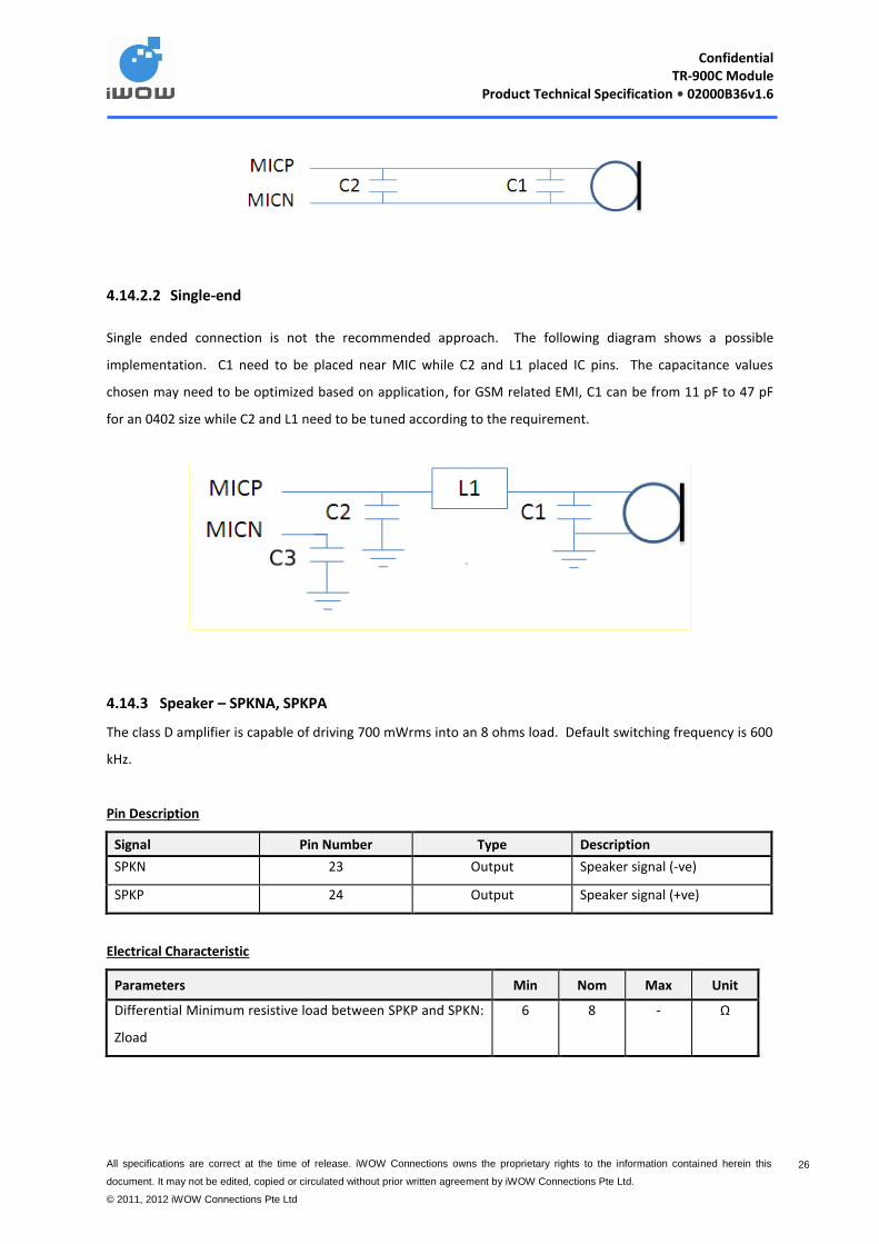
4.14.2.2 Single-end
Single ended connection is not the recommended approach. The following diagram shows a possible
implementation. C1 need to be placed near MIC while C2 and L1 placed IC pins. The capacitance values
chosen may need to be optimized based on application, for GSM related EMI, C1 can be from 11 pF to 47 pF
for an 0402 size while C2 and L1 need to be tuned according to the requirement.
4.14.3 Speaker – SPKNA, SPKPA
The class D amplifier is capable of driving 700 mWrms into an 8 ohms load. Default switching frequency is 600
kHz.
Pin Description
Signal Pin Number Type Description
SPKN 23 Output Speaker signal (-ve)
SPKP 24 Output Speaker signal (+ve)
Electrical Characteristic
Parameters Min Nom Max Unit
Differential Minimum resistive load between SPKP and SPKN:
Zload
6 8 - Ω
Confidential
TR-900C Module Product Technical Specification • 02000B36v1.6
All specifications are correct at the time of release. iWOW Connections owns the proprietary rights to the information contained herein this
document. It may not be edited, copied or circulated without prior written agreement by iWOW Connections Pte Ltd.
© 2011, 2012 iWOW Connections Pte Ltd
27 27
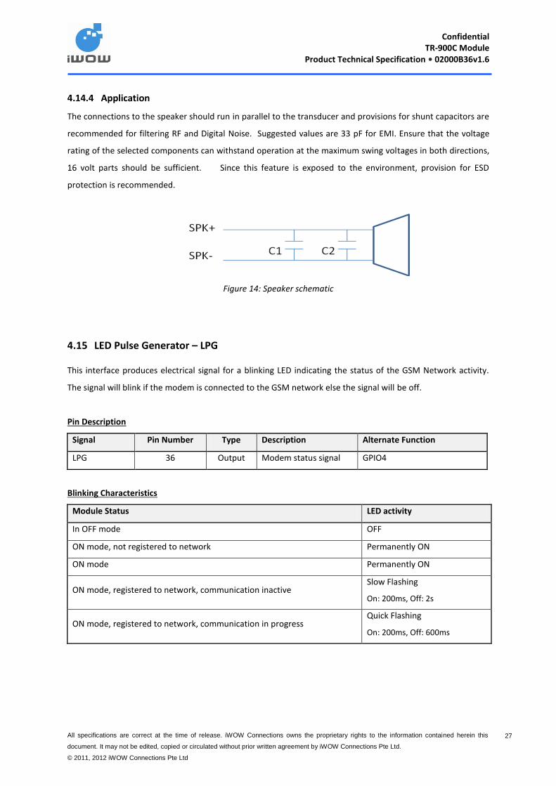
4.14.4 Application
The connections to the speaker should run in parallel to the transducer and provisions for shunt capacitors are
recommended for filtering RF and Digital Noise. Suggested values are 33 pF for EMI. Ensure that the voltage
rating of the selected components can withstand operation at the maximum swing voltages in both directions,
16 volt parts should be sufficient. Since this feature is exposed to the environment, provision for ESD
protection is recommended.
Figure 14: Speaker schematic
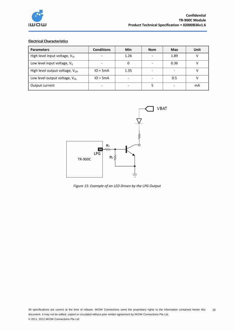
4.15 LED Pulse Generator – LPG
This interface produces electrical signal for a blinking LED indicating the status of the GSM Network activity.
The signal will blink if the modem is connected to the GSM network else the signal will be off.
Pin Description
Signal Pin Number Type Description Alternate Function
LPG 36 Output Modem status signal GPIO4
Blinking Characteristics
Module Status LED activity
In OFF mode OFF
ON mode, not registered to network Permanently ON
ON mode Permanently ON
ON mode, registered to network, communication inactive Slow Flashing
On: 200ms, Off: 2s
ON mode, registered to network, communication in progress Quick Flashing
On: 200ms, Off: 600ms
Confidential
TR-900C Module Product Technical Specification • 02000B36v1.6
All specifications are correct at the time of release. iWOW Connections owns the proprietary rights to the information contained herein this
document. It may not be edited, copied or circulated without prior written agreement by iWOW Connections Pte Ltd.
© 2011, 2012 iWOW Connections Pte Ltd
28 28
Electrical Characteristics
Parameters Conditions Min Nom Max Unit
High level input voltage, VIH - 1.26 - 1.89 V
Low level input voltage, VIL - 0 - 0.36 V
High level output voltage, VOH IO = 5mA 1.35 - - V
Low level output voltage, VOL IO = 5mA - - 0.5 V
Output current - - 5 - mA
Figure 15: Example of an LED Driven by the LPG Output
TR-900C

Confidential
TR-900C Module Product Technical Specification • 02000B36v1.6
All specifications are correct at the time of release. iWOW Connections owns the proprietary rights to the information contained herein this
document. It may not be edited, copied or circulated without prior written agreement by iWOW Connections Pte Ltd.
© 2011, 2012 iWOW Connections Pte Ltd
29 29
4.16 General Purposes Input / Output ports – GPIO
Each GPIO port can be configured individually as input or output ports through AT Commands.
Pin Description
Signal Pin Number Type Alternate Function
GPIO1 46 I/O DSR
GPIO2 43 I/O RI
GPIO3 12 I/O
GPIO4 36 I/O LPG
GPIO5 37 I/O
GPIO6 44 I/O DTR
GPIO7 45 I/O DCD
GPIO8 20 I/O
GPIO9 19 I/O
GPIO10 30 I/O SPI_CLK
GPIO11 29 I/O SPI_NCS0
GPIO12 32 I/O SPI_MISO
GPIO13 47 I/O CTS
GPIO14 48 I/O RTS
GPIO15 31 I/O SPI_MOSI
Electrical Characteristics
Parameters Conditions Min Nom Max Unit
High level input voltage, VIH - 1.26 - 1.89 V
Low level input voltage, VIL - 0 - 0.36 V
High level output voltage, VOH IO = 3mA 1.26 - - V
Low level output voltage, VOL IO = 3mA - - 0.45 V
Rated output current, IOL / IOH - - 3 - mA

Confidential
TR-900C Module Product Technical Specification • 02000B36v1.6
All specifications are correct at the time of release. iWOW Connections owns the proprietary rights to the information contained herein this
document. It may not be edited, copied or circulated without prior written agreement by iWOW Connections Pte Ltd.
© 2011, 2012 iWOW Connections Pte Ltd
30 30
4.17 Serial Peripheral Interface (SPI) – SPI_CLK, SPI_MISO, SPI_MOSI, SPI_NCS0, SPI_IRQ
The SPI bus includes clock (SPI_CLK), I/O (SPI_MISO, SPI_MOSI) and chip select (SPI_NCS0, SPI_NCS1) signal.
Note: Supports 1.8V SPI compliant devices.
Pin Description
Signal Pin Number Type Description Termination
SPI_CLK 30 Input/ Output SPI serial clock Open
SPI_MISO 31 Input/ Output SPI Data: Master in/ Slave out
I = SPI serial data master-in
O = SPI serial data slave-out
Open
SPI_MOSI 32 Input/ Output SPI data: Master out/Slave in
O = SPI serial data master-out
I = SPI serial data slave-in
Open
4.17.1 SPI Address 0
Pin Description:
Signal Pin Number Type Description Termination
SPI_NCS0 29 Output MSSPI chip select 0 output Open
4.17.2 SPI Interrupt
Pin Description:
Signal Pin Number Type Description Termination
SPI_IRQ 28 Input SPI interrupt request input Open
For hardware reference only. This feature is not enabled in the standard module firmware as it requires a
certain level of firmware customization depending on its intended application. Please contact iWOW for more
information.
Confidential
TR-900C Module Product Technical Specification • 02000B36v1.6
All specifications are correct at the time of release. iWOW Connections owns the proprietary rights to the information contained herein this
document. It may not be edited, copied or circulated without prior written agreement by iWOW Connections Pte Ltd.
© 2011, 2012 iWOW Connections Pte Ltd
31 31
4.18 2-Wire Serial Interface – I2C_SDA, I2C_SCL
This is a half-duplex serial port using 2-line for data transmission consisting of SDA data signal and SDL clock
signal. It can transfer at speeds up to 400Kbits/s (fast-mode).
Note: Supports 1.8V I2C compliant devices.
Pin Description
Signal Pin Number Type Default Function
I2C_SDA 27 Input/ Output 2- wire interface serial bi-directional data
I2C_SCL 26 Input/ Output 2- wire interface Master serial clock
Electrical Characteristics
Parameters Conditions Min Nom Max Unit
High level input voltage, (SDA and SCL), VIH - - - 1.8 V
Low level input voltage(SDA and SCL), VIL - 0 - - V
For hardware reference only. This feature is not enabled in the standard module firmware as it requires a
certain level of firmware customization depending on its intended application. Please contact iWOW for more
information.
4.19 RF interface
The RF input/output (ANT, pin 41) of the TR-900C is through one of the castellation pins with grounded
castellation pins at both sides. TR-900C RF interface has a characteristic impedance of 50. The matching
networks for an external antenna connection are not included in the module and should be placed on the
application board.
Pin Description
Signal Pin Number Type Description
ANT 41 - Antenna
GND 40,42 - Ground
Confidential
TR-900C Module Product Technical Specification • 02000B36v1.6
All specifications are correct at the time of release. iWOW Connections owns the proprietary rights to the information contained herein this
document. It may not be edited, copied or circulated without prior written agreement by iWOW Connections Pte Ltd.
© 2011, 2012 iWOW Connections Pte Ltd
32 32
4.19.1 General RF Guide
Below is a general guidelines when implement RF on application board.
Ensure the RF signals are routed with 50 characteristic impedance. Calculation have to be carried out to
ensure that thickness of the trace is 50 impedance and ensure impedance control for RF trace during
PCB manufacturing if necessary.
The choice of stripline or microstrip is dependent on the designer.
Ensure the RF trace is isolated and surrounded by two ground planes in order to protect the antenna line
from noisy signals (digital, bus, supply).
Keep the RF trace about 1cm away from any noisy signal in order to ensure a good RX sensitivity level.
Avoid crossing any un-shielded transmission line footprint with other signal tracks on different layers.
Keep the antenna line far away from the power supply lines.
Ensure the length of the line are not too long (no more than a few centimeters) to minimize the RF
insertion loss.
If possible, keep at least one layer of the PCB for the Ground plane only and use this layer as reference
Ground plane for the transmission line.
The other end of the 50 RF line can be connected to an RF connector or to a soldering pad in order to
connect an antenna.
Confidential
TR-900C Module Product Technical Specification • 02000B36v1.6
All specifications are correct at the time of release. iWOW Connections owns the proprietary rights to the information contained herein this
document. It may not be edited, copied or circulated without prior written agreement by iWOW Connections Pte Ltd.
© 2011, 2012 iWOW Connections Pte Ltd
33 33
4.19.2 RF Performance
Frequency Bands RF Sensitivity (dBm) (Nominal)
GSM 850/EGSM 900 -104dBm
DCS1800/ PCS1900 -102dBm
4.19.3 Recommendations
The antenna must fulfill the following requirements below:
Frequency Bands EGSM 900 DCS 2800 GSM 850 PCS 1900
TX Frequency 880 - 915 MHz 1710 - 1785 MHz 824 - 849 MHz 1850 - 1910 MHz
RX Frequency 925 - 960 MHz 1805 - 1880 MHz 869 - 894 MHz 1930 - 1990 MHz
Impedance 50 ohm
VSWR Rx max 1.5 : 1
VSWR Tx max 1.5 : 1
Typical radiated gain 0 dBi in one direction at least
The optimum operating frequency depends on the application. A dual-band or a quad band antenna must
operate in the above frequency bands.

Confidential
TR-900C Module Product Technical Specification • 02000B36v1.6
All specifications are correct at the time of release. iWOW Connections owns the proprietary rights to the information contained herein this
document. It may not be edited, copied or circulated without prior written agreement by iWOW Connections Pte Ltd.
© 2011, 2012 iWOW Connections Pte Ltd
34 34
5 Electrical & Reliability Characteristics
5.1 Electrical Characteristics
Parameter Description Min Nom Max Unit
Supply Input:
VBAT Battery Input Voltage 3.2 3.8 4.5 V
IBBURSTB Burst peak current - - 2.0 A
Regulated Output:
VBOUTB Output voltage 1.65 1.8 1.95 V
IBOUTB Rated output current - - 200 mA
SIM Card Related:
VSIM Output voltage to 3V SIM card 2.7 2.85 2.95 V
POWER ON/OFF Switch:
VTBIHTB High level input voltage 1.495 - - V
VTBILTB Low level input voltage - - 0.805 V
Digital Signal Characteristic (GPIO,UART):
VTBIHTB High-level input voltage 1.26 - 1.89 V
VTBILTB Low-level input voltage 0 - 0.36 V
VTBOHTB High-level output voltage at rated
current
1.26 - - V
VTBOLTB Low-level output voltage at rated
current
- - 0.45 V
ITBOHTB Rated output high current - 3 - mA
ITBOLTB Rated output low current - 3 - mA
Note: Due to the burst emission in GSM, the power supply (VBAT) must be able to handle high current peaks (1.5A max in EGSM band) in a short time.

Confidential
TR-900C Module Product Technical Specification • 02000B36v1.6
All specifications are correct at the time of release. iWOW Connections owns the proprietary rights to the information contained herein this
document. It may not be edited, copied or circulated without prior written agreement by iWOW Connections Pte Ltd.
© 2011, 2012 iWOW Connections Pte Ltd
35 35
5.2 Absolute Maximum Ratings
Below list the absolute maximum ratings over operating free-air temperature:
Parameter Rating
Supply voltage range, VBAT -0.3 V to +4.5 V
Voltage on any input -0.2 V to +2.0 V
Peak output current on VIO (Note) 1.8V
Peak output current on VSIM 15 mA
Free-air temperature range. -30oC to 85
oC
Storage temperature range -40 oC to 85
oC
Note: iWOW reserved current usage for on-board features and future expansion. Customer requires more than
100mA, please contact iWOW.

Confidential
TR-900C Module Product Technical Specification • 02000B36v1.6
All specifications are correct at the time of release. iWOW Connections owns the proprietary rights to the information contained herein this
document. It may not be edited, copied or circulated without prior written agreement by iWOW Connections Pte Ltd.
© 2011, 2012 iWOW Connections Pte Ltd
36 36
5.3 Reliability Compliance
The TR-900C module complied with the following test cases.
S/N Type of test Conditions
1 Dry heat Temperature: +85°C ±2°C Test duration: 16h Humidity in the test chamber: < 50%
2 Humidity Test Temperature: +65°C RH: 95% Rate of temperature change: dT/dt >= ± 3°C/min Recovery time: 3 hours
3 Temperature change (shock)
Low temperature: -40°C ±2°C High temperature: +85°C ±2°C Changeover time: < 30s (dual chamber system) Test duration: 1h Number of repetitions: 100
4 Damp heat cyclic High temperature: +55°C ±2°C Low temperature: +25°C ±2°C Humidity: 93% ±3% Number of repetitions: 6 Test duration: 12h + 12h
5 Cold storage Test Ab, -40°C / 16 h Unpackaged equipment & power supply unconnected The product was verified after test
6 Dry storage Test Bb, +85°C / 16 h Unpackaged equipment & power supply unconnected The product was verified after test
7 Change of storage temperature
Test Nb, 5 cycles (3h @-20°C , 3°C/min, 3h @+55°C ) The product was be verified during test
8 Sinusoidal vibration Test Fc: 5 to 9Hz : 3,5mm 9 to 150Hz : 1g scan : 1 octave / Min (10cycles/axe) The product shall be verified during test
9 Vibration Frequency range: 10-20Hz; acceleration: 3.1mm amplitude Frequency range: 20-500Hz; acceleration: 5g Duration: 2h per axis = 10 cycles; 3 axes
10 Shock half-sinus Acceleration: 500g Shock duration: 1msec 1 shock per axis 6 positions (± x, y and z)
Confidential
TR-900C Module Product Technical Specification • 02000B36v1.6
All specifications are correct at the time of release. iWOW Connections owns the proprietary rights to the information contained herein this
document. It may not be edited, copied or circulated without prior written agreement by iWOW Connections Pte Ltd.
© 2011, 2012 iWOW Connections Pte Ltd
37 37
6 General Recommendation
6.1 General Layout Guideline
Below is a general layout guideline:
It is advisable to use a 4 layer PCB with minimum 1 layer of uniform ground plane as this will help to
eliminate any ESD or EMC interferences.
Stack-ups should also be planned carefully to ensure proper shielding of critical traces. (Decision should be
made on the number of signals layers and plane such as power, ground, analogue, digital and RF).
Good PCB layout comes with good placement of components. EMI is usually caused by poor PCB layout.
Identify all the critical parts of the components before layout. After which, routing of the traces will be
neater and less susceptible to interference.
All ground planes should be continuous. This provides better grounding and return path. Good ground
plane also helps in heat dissipation and provide good EMI shielding.
Ensure all ground planes are connected with multiple vias to reduce the impedance between the ground
plane.
All ground planes should have low impedances connections.
Ensure the power supply lines to the pin connectors have high impedance.
Design the pin connections with proper isolation between the RF signals and noisy traces.
Analogue and digital ground should be properly isolated.
Remove unnecessary unconnected copper fills.
Do not route any traces under the module. A ground plane is preferred underneath the module to provide
optimum shielding.
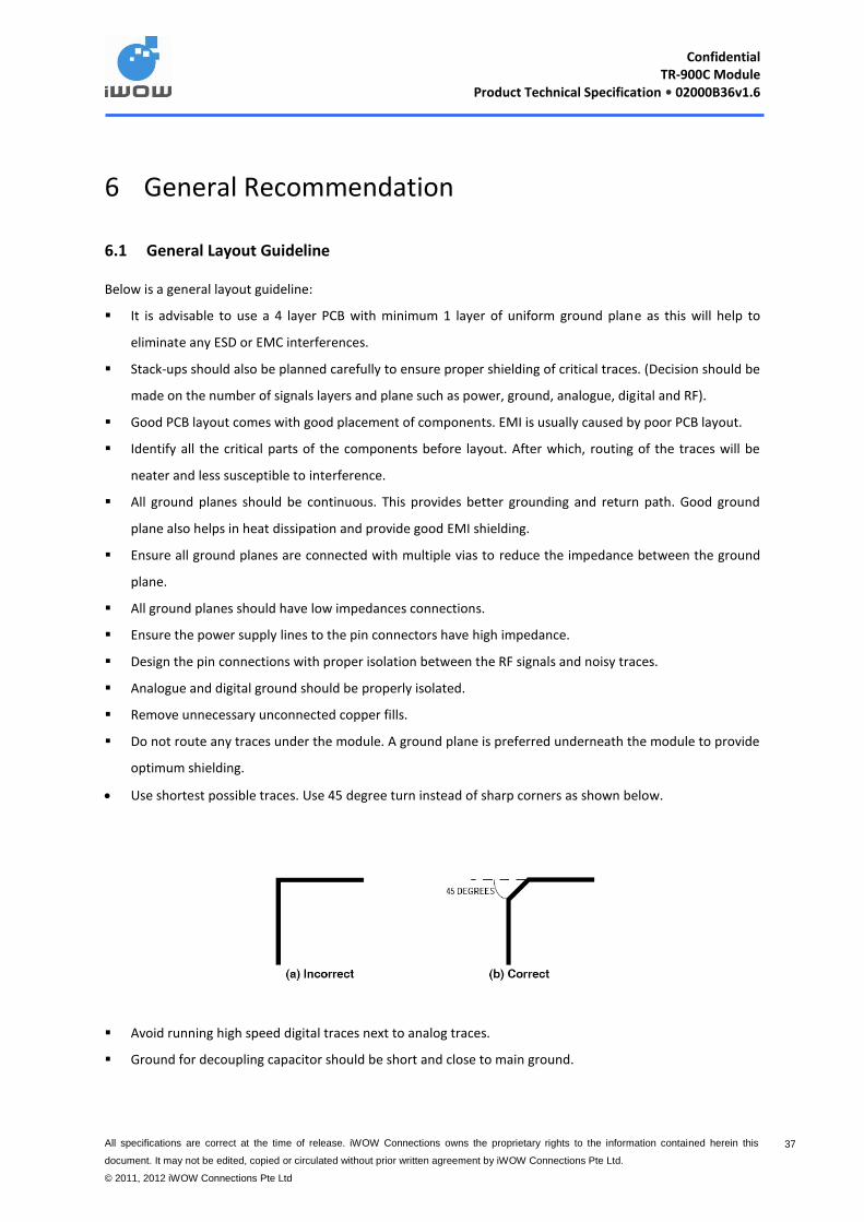
Use shortest possible traces. Use 45 degree turn instead of sharp corners as shown below.
Avoid running high speed digital traces next to analog traces.
Ground for decoupling capacitor should be short and close to main ground.
Confidential
TR-900C Module Product Technical Specification • 02000B36v1.6
All specifications are correct at the time of release. iWOW Connections owns the proprietary rights to the information contained herein this
document. It may not be edited, copied or circulated without prior written agreement by iWOW Connections Pte Ltd.
© 2011, 2012 iWOW Connections Pte Ltd
38 38
6.2 Firmware Upgrade
For firmware upgrade, there are two alternatives:
o For UART approach (recommended), application board need to provide for access to UART_TX
UART_RX, 1V8 and VBAT.
o For USB approach, application board need to provide for access to USB signals and VBAT.
Note: For both approaches, all relevant signals and RESET signal needs to be isolated from application
board effects.
6.3 Power Supply Guideline
The power supply is one of the key issues in the design of an application and careful attention should be paid
to the following:
Do not connect main power input directly to the module. Ensure the filtering components are in place.
Add a ferrite bead if necessary.
A low ESR capacitor, preferably tantalum of > 1mF, is to be placed as close as possible to the module’s
voltage supply input. Other filtering capacitors should also be placed nearby if necessary.
It may be necessary to place additional 33pF close to the module when there are RF interferences.
Power supply must be able to deliver high current because of the GSM/GPRS burst emission. To achieve
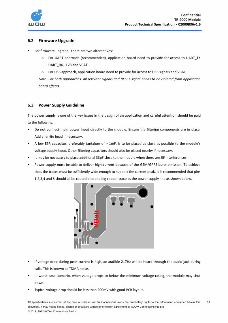
that, the traces must be sufficiently wide enough to support the current peak. It is recommended that pins
1,2,3,4 and 5 should all be routed into one big copper trace as the power supply line as shown below.
If voltage drop during peak current is high, an audible 217Hz will be heard through the audio jack during
calls. This is known as TDMA noise.
In worst-case scenario, when voltage drops to below the minimum voltage rating, the module may shut
down.
Typical voltage drop should be less than 200mV with good PCB layout.
VB
att

Confidential
TR-900C Module Product Technical Specification • 02000B36v1.6
All specifications are correct at the time of release. iWOW Connections owns the proprietary rights to the information contained herein this
document. It may not be edited, copied or circulated without prior written agreement by iWOW Connections Pte Ltd.
© 2011, 2012 iWOW Connections Pte Ltd
39 39
If no audio circuitries are required, typical voltage drop can be higher as long as it meets the minimum
voltage rating.
A good ground plane should be placed closed to power trace.
Use multiple vias to ensure good grounding on a multiple layer PCB board.
Use big vias size to connect between layers so as to reduce the impedances of the vias.

Confidential
TR-900C Module Product Technical Specification • 02000B36v1.6
All specifications are correct at the time of release. iWOW Connections owns the proprietary rights to the information contained herein this
document. It may not be edited, copied or circulated without prior written agreement by iWOW Connections Pte Ltd.
© 2011, 2012 iWOW Connections Pte Ltd
40 40
7 Incoming Inspection Criteria for TR-900C Module
Confidential
TR-900C Module Product Technical Specification • 02000B36v1.6
All specifications are correct at the time of release. iWOW Connections owns the proprietary rights to the information contained herein this
document. It may not be edited, copied or circulated without prior written agreement by iWOW Connections Pte Ltd.
© 2011, 2012 iWOW Connections Pte Ltd
41 41
7.1 Logistics Inspection
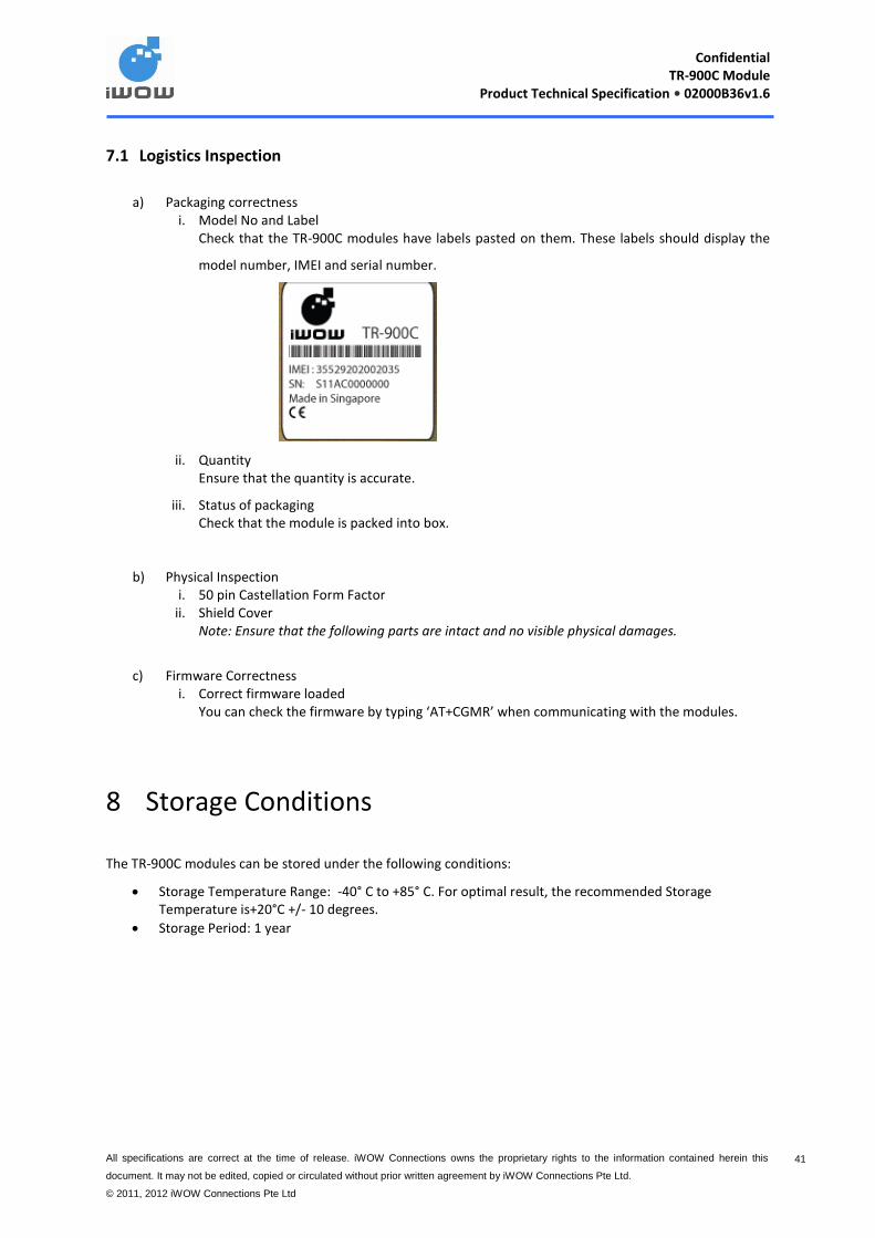
a) Packaging correctness i. Model No and Label
Check that the TR-900C modules have labels pasted on them. These labels should display the
model number, IMEI and serial number.
ii. Quantity Ensure that the quantity is accurate.
iii. Status of packaging Check that the module is packed into box.
b) Physical Inspection i. 50 pin Castellation Form Factor
ii. Shield Cover Note: Ensure that the following parts are intact and no visible physical damages.
c) Firmware Correctness
i. Correct firmware loaded You can check the firmware by typing ‘AT+CGMR’ when communicating with the modules.
8 Storage Conditions
The TR-900C modules can be stored under the following conditions:
Storage Temperature Range: -40° C to +85° C. For optimal result, the recommended Storage Temperature is+20°C +/- 10 degrees.
Storage Period: 1 year
Confidential
TR-900C Module Product Technical Specification • 02000B36v1.6
All specifications are correct at the time of release. iWOW Connections owns the proprietary rights to the information contained herein this
document. It may not be edited, copied or circulated without prior written agreement by iWOW Connections Pte Ltd.
© 2011, 2012 iWOW Connections Pte Ltd
42 42
9 Packaging Information
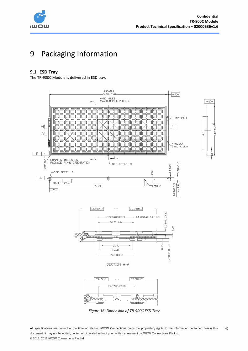
9.1 ESD Tray The TR-900C Module is delivered in ESD tray.
Figure 16: Dimension of TR-900C ESD Tray
Confidential
TR-900C Module Product Technical Specification • 02000B36v1.6
All specifications are correct at the time of release. iWOW Connections owns the proprietary rights to the information contained herein this
document. It may not be edited, copied or circulated without prior written agreement by iWOW Connections Pte Ltd.
© 2011, 2012 iWOW Connections Pte Ltd
43 43
9.2 Module Box Description Description: Conductive Box with ESD trays vacuum pack
Box Size: 344 x 230 x 68 (H)mm
Box Material: Single Wall – 275k/275k
Box Print: Conductive Ink Coating
Quantity: 200 pcs /vacuum pack
The following information is labeled on the Module Box.
Model No.
IMEI Range
Firmware
Qty
Baud rate
9.3 Product Handling
TR-900C is ESD sensitive (Voltage < 1kV)and require special ESD precautions typically applied to ESD sensitive
components.
It is recommended to use standard ESD precautions, as described in the following norm:
Always discharge before entering ESD area.
Operator handling the product should use a grounded wrist strap with good skin contact
Isolative footwear should also be worn to prevent static discharge flowing from body to ground.
Parts should be placed on approved static dissipative materials.
A static control workstation should be provided with ESD protective work surface and proper grounding.
Proper hand tools, ie.pliers, tweezers should be used when handling products.
Soldering iron should have the tip properly grounded.
Static control area should be made available for movements and transportation of product between 2
points.
Recommended humidity should be between 30% - 70%
Confidential
TR-900C Module Product Technical Specification • 02000B36v1.6
All specifications are correct at the time of release. iWOW Connections owns the proprietary rights to the information contained herein this
document. It may not be edited, copied or circulated without prior written agreement by iWOW Connections Pte Ltd.
© 2011, 2012 iWOW Connections Pte Ltd
44 44
Wear proper clothing and garments in an ESD environment.
For more information on ESD, please refer to ANSI/ESD S20.20
* Improper ESD control and poor handling will result in electrical failure and reliability problems
9.4 Moisture Sensitivity
The TR-900C is rated moisture sensitivity level 3 (MSL3) described in IPC/JEDEC JSTD-020. Exposures to
moisture levels or solder reflow temperatures, which exceed those stated in JSTD-020, can result in yield and
reliability degradation.
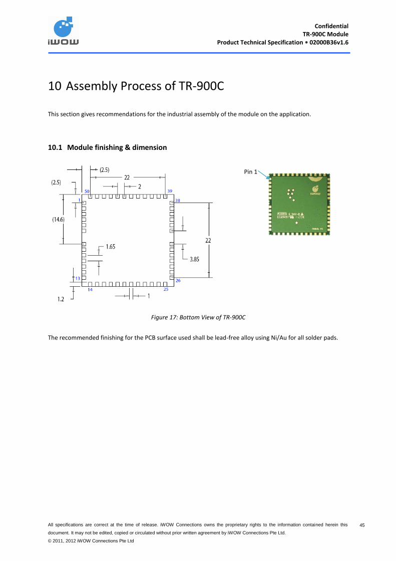
Confidential
TR-900C Module Product Technical Specification • 02000B36v1.6
All specifications are correct at the time of release. iWOW Connections owns the proprietary rights to the information contained herein this
document. It may not be edited, copied or circulated without prior written agreement by iWOW Connections Pte Ltd.
© 2011, 2012 iWOW Connections Pte Ltd
45 45
10 Assembly Process of TR-900C
This section gives recommendations for the industrial assembly of the module on the application.
10.1 Module finishing & dimension
Figure 17: Bottom View of TR-900C
The recommended finishing for the PCB surface used shall be lead-free alloy using Ni/Au for all solder pads.
Pin 1

Confidential
TR-900C Module Product Technical Specification • 02000B36v1.6
All specifications are correct at the time of release. iWOW Connections owns the proprietary rights to the information contained herein this
document. It may not be edited, copied or circulated without prior written agreement by iWOW Connections Pte Ltd.
© 2011, 2012 iWOW Connections Pte Ltd
46 46
10.1.1 Recommended footprint
Below is the recommended footprint for application board.
Figure 18: Recommended Footprint
Below are some guidelines when laying TR-900C footprint:
It is recommended to have a ground area under TR-900C.
Ensure that there is no trace laid under TR-900C.
It is recommended to have a placement clearance of 2mm around TR-900C for easy rework.
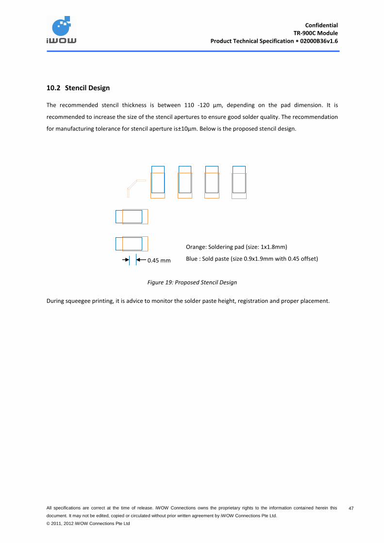
Confidential
TR-900C Module Product Technical Specification • 02000B36v1.6
All specifications are correct at the time of release. iWOW Connections owns the proprietary rights to the information contained herein this
document. It may not be edited, copied or circulated without prior written agreement by iWOW Connections Pte Ltd.
© 2011, 2012 iWOW Connections Pte Ltd
47 47
10.2 Stencil Design
The recommended stencil thickness is between 110 -120 µm, depending on the pad dimension. It is
recommended to increase the size of the stencil apertures to ensure good solder quality. The recommendation
for manufacturing tolerance for stencil aperture is±10µm. Below is the proposed stencil design.
Orange: Soldering pad (size: 1x1.8mm)
Blue : Sold paste (size 0.9x1.9mm with 0.45 offset)
Figure 19: Proposed Stencil Design
During squeegee printing, it is advice to monitor the solder paste height, registration and proper placement.
0.45 mm
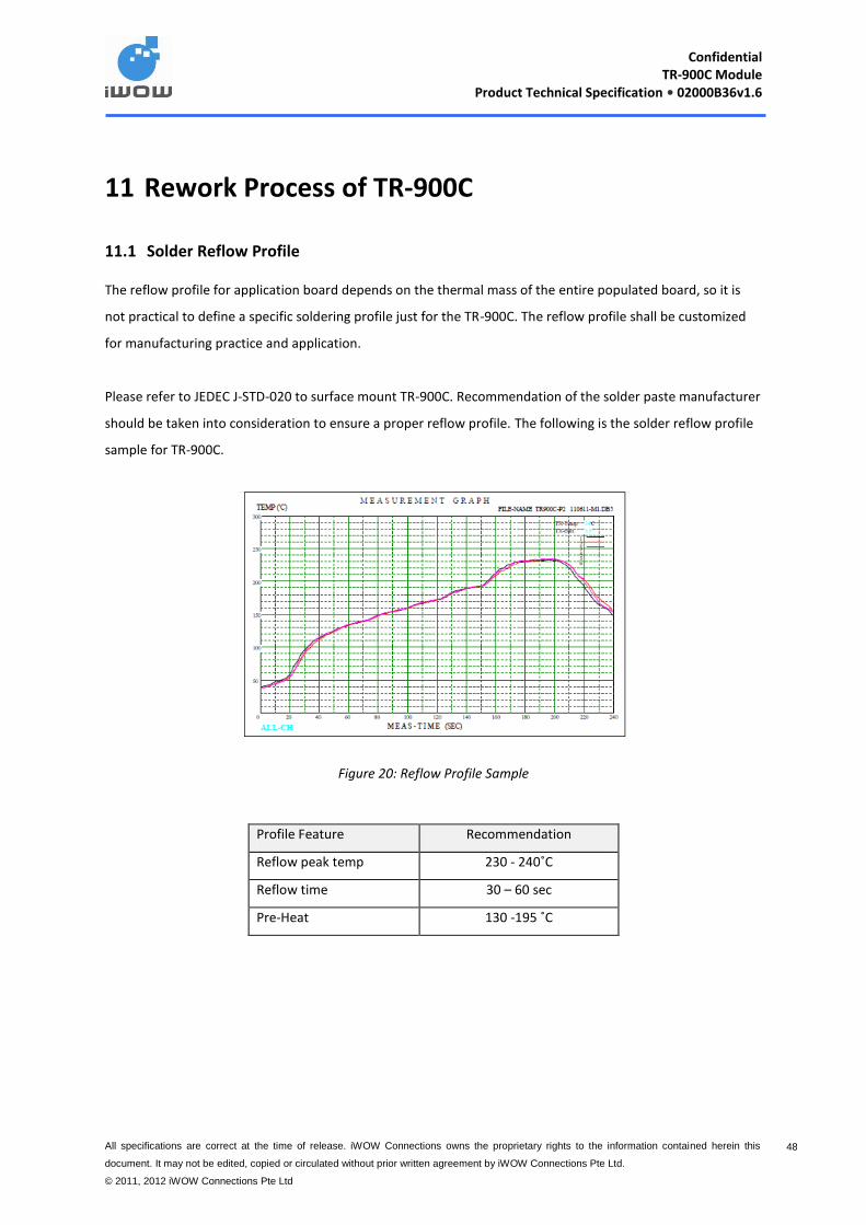
Confidential
TR-900C Module Product Technical Specification • 02000B36v1.6
All specifications are correct at the time of release. iWOW Connections owns the proprietary rights to the information contained herein this
document. It may not be edited, copied or circulated without prior written agreement by iWOW Connections Pte Ltd.
© 2011, 2012 iWOW Connections Pte Ltd
48 48
11 Rework Process of TR-900C
11.1 Solder Reflow Profile
The reflow profile for application board depends on the thermal mass of the entire populated board, so it is
not practical to define a specific soldering profile just for the TR-900C. The reflow profile shall be customized
for manufacturing practice and application.
Please refer to JEDEC J-STD-020 to surface mount TR-900C. Recommendation of the solder paste manufacturer
should be taken into consideration to ensure a proper reflow profile. The following is the solder reflow profile
sample for TR-900C.
Figure 20: Reflow Profile Sample
Profile Feature Recommendation
Reflow peak temp 230 - 240˚C
Reflow time 30 – 60 sec
Pre-Heat 130 -195 ˚C
Confidential
TR-900C Module Product Technical Specification • 02000B36v1.6
All specifications are correct at the time of release. iWOW Connections owns the proprietary rights to the information contained herein this
document. It may not be edited, copied or circulated without prior written agreement by iWOW Connections Pte Ltd.
© 2011, 2012 iWOW Connections Pte Ltd
49 49
11.2 Rework Guidelines
The following description is a guideline for the development of a successful removal process for TR-900C. This
guideline is general a recommended practice. The users must apply their actual experiences and development
efforts to optimize the process for their manufacturing techniques.
If the component floor life has been exceeded, it is strongly recommended that the application board be baked
for at least 4 hours at 125°C to remove any residual moisture from the assembly prior to rework. This bake
should prevent moisture-induced cracking or delaminating of the PCB.
11.2.1 Removal of TR-900C Using Hot Air Gun
A hot air gun can be used to remove the module from main PCB by follow below recommended setting:
Profile Feature Recommendation
Hot air gun temperature 360 ±10% °C
Recommended time 60 to 90 sec
To easier removal this module, perform a hot air gun on a side of module, and then continue to other side. A
mechanical tool can also be used to support, for example tweezers to lift up the module during performed hot
air blowing on it.
11.2.2 Module Pad Cleaning
In order to ensure proper contact when the TR-900C is retested, the following cleaning process should be used
as a guideline. It is recommended to use a combination of a soldering iron and desoldering braid or solder wick
to remove residual solder from the exposed pads. Minimize the amount of time the soldering iron is in contact
with the de-soldering braid. Once the residual solder is removed, the pads should be cleaned with a solvent
that is recommended for the specific type of paste used by paste manufacturer.

Confidential
TR-900C Module Product Technical Specification • 02000B36v1.6
All specifications are correct at the time of release. iWOW Connections owns the proprietary rights to the information contained herein this
document. It may not be edited, copied or circulated without prior written agreement by iWOW Connections Pte Ltd.
© 2011, 2012 iWOW Connections Pte Ltd
50 50
11.2.3 Site Redress
Once the TR-900C has been removed, the residual solder that remains on the pads must be removed. The PCB
site is very fragile because of its small pad sizes. To avoid damaging the pads or solder mask, the site redress
process must be performed very carefully. “No Clean” flux is applied to the site after component removal. Using
a temperature-controlled soldering iron fitted with a small flat blade, gently apply solder braid that has been
presoaked in flux over the PCB pads. Once the residual solder is removed, the pads should be cleaned with a
solvent that is recommended for the specific type of paste used by paste manufacturer.
11.2.4 Module Replacement
Replacement of TR-900C can be done by 2 methods:
Manual Soldering, and Use a mini stencil for solder paste printing prior reflow process.
As its solder pads of TR-900C are visible, a manual placement and soldering can be done. Recommended solder
iron temperature setting are as below:
Profile Recommendation
Temperature 340 – 360°C
Touch Time 3 – 5 Sec
When mini-stencil is used, it should have same thickness and aperture as the stencil used for original module
attachment. The same reflow profile for module attachment should be applied. Visual inspection is performed
after complete re-soldering module into PCB. Check points are on the solderability quality includes dwetting
solder, no solder, less solder, etc.
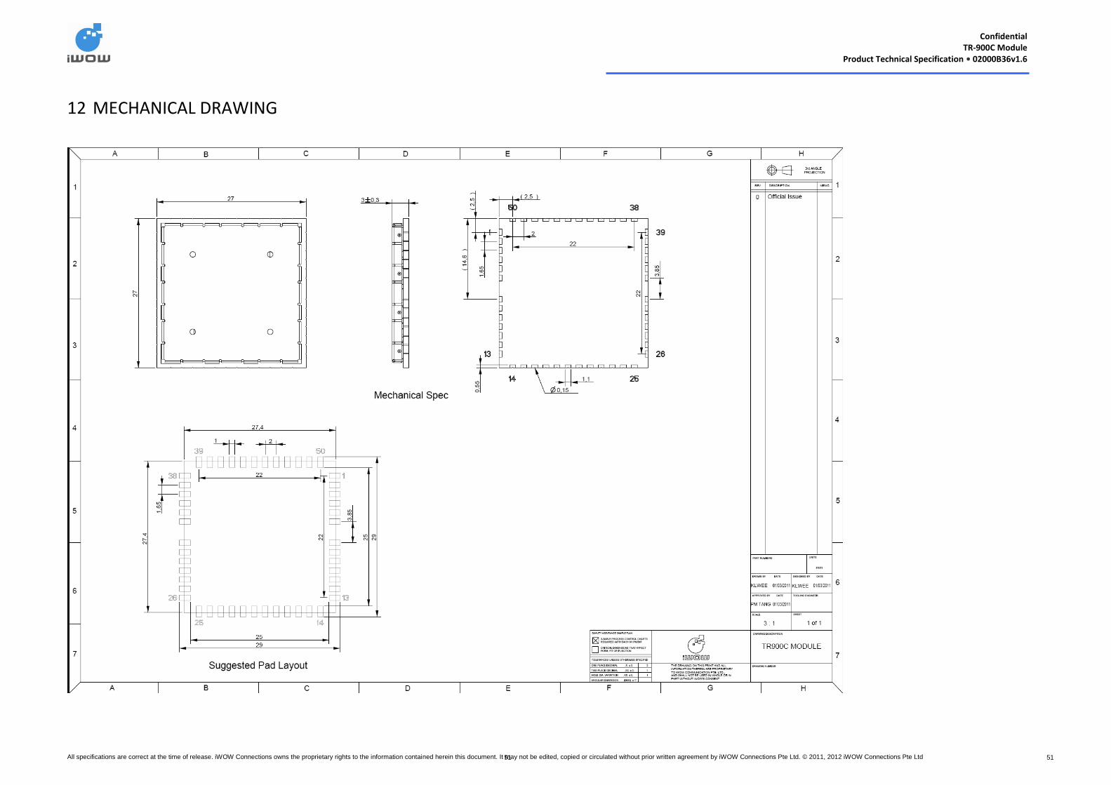
Confidential
TR-900C Module Product Technical Specification • 02000B36v1.6
All specifications are correct at the time of release. iWOW Connections owns the proprietary rights to the information contained herein this document. It may not be edited, copied or circulated without prior written agreement by iWOW Connections Pte Ltd. © 2011, 2012 iWOW Connections Pte Ltd 51 51
12 MECHANICAL DRAWING
Confidential
TR-900C Module Product Technical Specification • 02000B36v1.6
All specifications are correct at the time of release. iWOW Connections owns the proprietary rights to the information contained herein this
document. It may not be edited, copied or circulated without prior written agreement by iWOW Connections Pte Ltd. © 2011, 2012 iWOW
Connections Pte Ltd
52 52
13 SUPPORT/ CONTACT US
For distributor clients, please contact your respective distributor FAE.
For direct clients, please contact iWOW FAE (Technical Support Department) or email us at
For general enquiries please contact us at:
iWOW Connections Pte Ltd
1 Lorong 2 Toa Payoh, #04-01
Yellow Pages Building
Singapore 319637
Office: (65) 6748 8123
Fax : (65) 6748 2668
Email: [email protected]
Website: http://www.iWOW.com.sg