for examinations held after 1 october 2015 - portal · pdf filefor examinations held after 1...
TRANSCRIPT

Radio Communications Foundation
Intermediate Radio AmateurExaminations Specification
For Examinations held after 1 October 2015
Publication date: 15 July 2015

Intermediate syllabus Page 2 Issue 5e
Contents
Section Page
1 Introduction 3
2 Syllabus 6
3 Examination Schedule 28 Document changes
Issue 5 June 2008 Changes in Introduction and syllabus items 1a, 2a, 3b1, 3b2,
3d2, 3d3, 3d4, 3e1, 2e2, 3e3, new 3f1, 3f2, 3f3, 3f4, 3g2, 3h1, 3h2, 3i5, new 3h7, old 3i1 deleted, 4e4, 4j1, 5a6, 5b1, 7d1, 9e3
Clarifications in 3i2, 3i6, 3j1, 4i1, 5d1, 9e1.
5a Nov 2008 Editorial corrections to Document changes issue 5, key features page 3, 3j3, 5a3, 5b1, 9e1 and questions 15 and 25 in the Examination Schedule.
Capacitors not passing DC added back in to 3f2, correcting an omission in change from version 4a to 5. No other changes in syllabus requirements.
5b Jan 2010 Update address for the RSGB Examination Department on page 4.
5c June 2013 Add text to the Introduction on the aim of the examination.
Reference to Optical Marking in the Introduction.
Edit 7c.1 and 7c.2 to remove references to analogue TV artefacts and clarify digital TV artefacts.
5d September 2013 Editorial correction; time allowed 1 hour 25 minutes.
5e July 2015
For exams from 1 October 2015
Editorial change to recognise new Licence text. Changed syllabus item 2c1 from
‘Recall that the Licensee must transmit the Callsign printed in the Licence during CQ calls, when establishing communication and every 15 minutes during long periods of transmission.’
to ‘Recall the requirements for station identification.’

Intermediate syllabus Page 3 Issue 5e
Section 1
Introduction The Intermediate Radio Amateur Examination is part of a structured suite of three examinations recognised by Ofcom to give access to the amateur radio bands. Each higher grade of certificate gives the potential user increased privileges. The Advanced Certificate in Radio Communications allows the user to apply for an Amateur Radio Licence that is recognised internationally.
The aim of the suite of examinations is to verify and assure the regulator that successful candidates have
knowledge of the legal and ethical requirements of amateur radio an understanding of safe working practices and are mindful of the safety of others a secure foundation for further study of radio science and technology knowledge of good operating practices and procedures an understanding of basic electronic components and systems relevant to amateur
radio an understanding of simple radio communications equipment through the
construction of radio related projects, fault finding and remediation
to a standard appropriate to the level of amateur radio licence addressed by their examination.
The Foundation Examination is the entry level to amateur radio. The requirements are contained in the “Foundation Amateur radio Examination Specification”.
This specification sets out the requirements for the second tier in the three-tier structure. It assumes that candidates have successfully fulfilled the requirements of the Foundation Licence and passed the associated examination.
Prior Learning and Progression
The Intermediate Certificate allows progression from the Foundation Certificate and may be followed by the Advanced Certificate giving access to the Full licence. The candidate may progress at his or her own pace, as far as desired, but must pass the examinations in ascending order. It is also a requirement that the practical assessment at Foundation and Intermediate levels are to be completed before sitting the examinations.
It is permissible to undertake the practical assessment for the Intermediate Examination before sitting the Foundation Examination. The candidate should sit the Intermediate Examination within 12 months of the relevant practical assessment.
Key Features of RCF Examinations
Part of a progressive system of learning, designed to promote an understanding of radio communication science, technology and practice sufficient to allow the licensed operator to safely work on the amateur radio bands.
Clear presentation of content for easy reference.
The examination suite as a whole provides a backbone of theoretical knowledge whilst at the same time requiring ‘on-air’ experience and practical skills.
Intermediate syllabus Page 4 Issue 5e
A student workbook is available, covering the syllabus and is suitable for self-study if desired.
Can be used within schools to enrich the Science and Technology and the wider curriculum.
The Intermediate Assessment
Two methods of assessment are used. A practical skills assessment is detailed in sections 10d, e and f of the syllabus. This assessment must be undertaken by a Registered Assessor, who may also be the tutor. This is followed by an examination of 45 multiple-choice questions each with four possible responses, which covers the remainder of the syllabus. The examination lasts 1hour 25 minutes.
The examination should normally be sat within 12 months of completing the Practical Assessment.
Papers are available at two week’s notice. These are indicatively marked locally, subject to validation using the Optical Mark sheet.
The results will also be uploaded to the Ofcom licensing database. Candidates will use their candidate number and password to make on-line application for their licence. A postal application option is available.
Examinations must be carried out at an RSGB registered centre.
Candidates with disabilities
Arrangements can be made for candidates with disabilities to demonstrate skills and knowledge by whatever means is judged appropriate.
Applications for special arrangements should be made well in advance of the examination to the Radio Society of Great Britain (RSGB) and will normally require a medical certificate advising the appropriate method of assessment or examination. Any waiver granted will be shown on the register and Assessment Sheet (RAS) issued by the RSGB Examination Department.
Appeals after the examination citing disabilities or learning difficulties not previously declared cannot be considered.
Examination Department Radio Society of Great Britain 3 Abbey Court Fraser Road Priory Business Park Bedford MK44 3WH
The Syllabus
The key points of study are shown under Assessment Objectives. The words “recall” and “understand” are used to denote differing levels of comprehension.
Recall indicates the need to remember a fact and apply it fairly directly to a question or situation. A thorough understanding of why the fact is so and the full range of circumstances in which it is applicable is not required, but questions will expect a basic understanding.
Understand indicates the need for a more detailed knowledge of the subject, fully appreciating why the point is correct and the range of circumstances in which it is relevant

Intermediate syllabus Page 5 Issue 5e
and applicable. Typically, this will be where the candidates will find themselves having to make judgements or apply a practice to a wider range of circumstances.
Examination Questions
Examination questions may assume background knowledge of the basic principles from all parts of the Foundation and Intermediate syllabuses; questions themselves will be clearly aimed at the relevant syllabus items.
It will be assumed that the candidate has some familiarity with operating practices and procedures as covered in the Foundation practical assessment and exam specification.
Some time spent on-air either as a listener or as an operator at Foundation level will be advantageous in understanding the purpose and context of syllabus items and examination questions.
Examination Schedule
The schedule shows the allocation of syllabus topics to questions on the examination paper.
Pass Mark
The pass mark is 60% or 27 correct questions out of a total of 45.
Language
The language of assessment will be English.
Formulae
Few formulae require to be remembered and a formula sheet will NOT be provided during the examination.
Training
Attendance at a training course is not compulsory but is strongly advised. Soldering, for example, is a skill best taught and the work inspected so that suitable guidance can be given. This is not readily achievable with reading material alone although multi-media distant learning materials may be of benefit.
Sample question papers are available at www.rsgb.org/tutors/intermediate.
Updates
Updates to this specification will be made from time to time and the latest version can be obtained from the RCF website www.commsfoundation.org/rce. Where the update involves a significant change to the specification, the date from which the specification is valid for examinations will be amended to show the new period of validity. A minimum of six months notice will be given.
Tutors should note that external changes, such as to licence conditions, may occur at shorter notice, which may result in examinations continuing to be set on the previous conditions immediately after the change. Changes to the licence schedule should not affect the examination because the schedule is provided for reference.

Intermediate syllabus Page 6 Issue 5e July 2015
S y l l a b u s A s s e s s m e n t O b j e c t i v e s
1. Amateur Radio
1a Amateur Licences and Callsigns
1a.1 Recall the various types of Amateur Licence (Foundation, Intermediate, Full), and identify their Callsigns, including Regional Secondary Locators and optional suffixes /A, /P, /M and /MM. The optional club secondary locators are not examined.
2. Licensing Conditions
2a Operators
2a.1 Recall that an Intermediate Licensee may operate the Radio Equipment of any other UK licensed amateur under that person’s direct supervision using the supervisor’s callsign, and obeying the terms of the supervisor’s licence.
Recall that an Intermediate licensee may similarly supervise operation by another UK licensed amateur and that operation should be within the limitations and privileges of the supervisor’s licence and using the supervisor’s Callsign.
Recall that an Intermediate Licensee may (with permission) use another amateur’s radio equipment unsupervised, but using the callsign and conditions of his or her own licence.
Note: The term ‘Radio Equipment’ (in initial capitals) is a defined licence term meaning the equipment used and identified by the operator’s callsign. If a visiting amateur uses the radio equipment with his callsign, it is his Radio Equipment.
2b Messages 2b.1 Recall the Radio Equipment must not be used for business or advertising purposes.
2b.2 Recall that the Licensee may pass messages on behalf of a User Service and may permit a member of the User Service to use the Radio Equipment to send messages.
Recall the identity of the Users Services.
Note: It is only necessary to remember the User Services named in clause 17(1)(qq) and that the Police, Fire, Ambulance and Coastguard are included in the ‘Category 1 and 2 responders’ along with local government.
2c Location and identification 2c.1 Recall the requirements for station identification.

Intermediate syllabus Page 7 Issue 5e July 2015
S y l l a b u s A s s e s s m e n t O b j e c t i v e s
2c.2 Recall the meaning of ‘Main Station Address’, ‘Alternative Address’ ‘Temporary Location’ and ‘Mobile’.
2c.3 Recall that the Licence does not permit operation from an aircraft or from vessel on the seaward side of the low-water line as marked on official charts.
2c.4 Recall that other Administrations (foreign countries) do not routinely recognise the Intermediate Licence.
2d Unattended operation
2d.1 Recall that the Licensee may conduct Unattended Operation of a Beacon, for the purposes of direction-finding competitions, for remote control of the main station or for digital communications.
Recall that the remote control link must be by radio in an amateur band, limited to 500mW maximum transmit power.
Recall that unattended operation does not include providing for general use by other amateurs.
2e Log
2e.1 Recall that a person authorised by Ofcom may require the Licence holder to keep a log of all transmissions made over a specified period of time.
2f Apparatus 2f.1 Recall that transmissions from the station must not cause undue interference to other radio users.
2f.2 Recall that the Licensee must reduce any emissions causing interference, to the satisfaction of a person authorised by Ofcom. Understand that this may include a reduction in transmit power or any other action required to reduce emissions to an acceptable level.
2f.3 Recall the Licensee must carry out tests from time to time to ensure that the station is not causing Undue Interference.
2g Licensee’s details and revocation
2g.1 Recall that the Licensee must give immediate notice to Ofcom of any change to the Licensee’s name, Main Station Address or mailing address.
Recall that the licensee must confirm that the details shown on the licence remain valid at least once every five years.
Recall that the licence can be revoked by Ofcom for breaches of licence conditions or for non-confirmation of licence details.
Intermediate syllabus Page 8 Issue 5e July 2015
S y l l a b u s A s s e s s m e n t O b j e c t i v e s
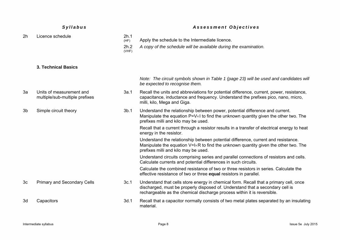
2h Licence schedule 2h.1 (HF) Apply the schedule to the Intermediate licence.
A copy of the schedule will be available during the examination. 2h.2 (VHF)
3. Technical Basics
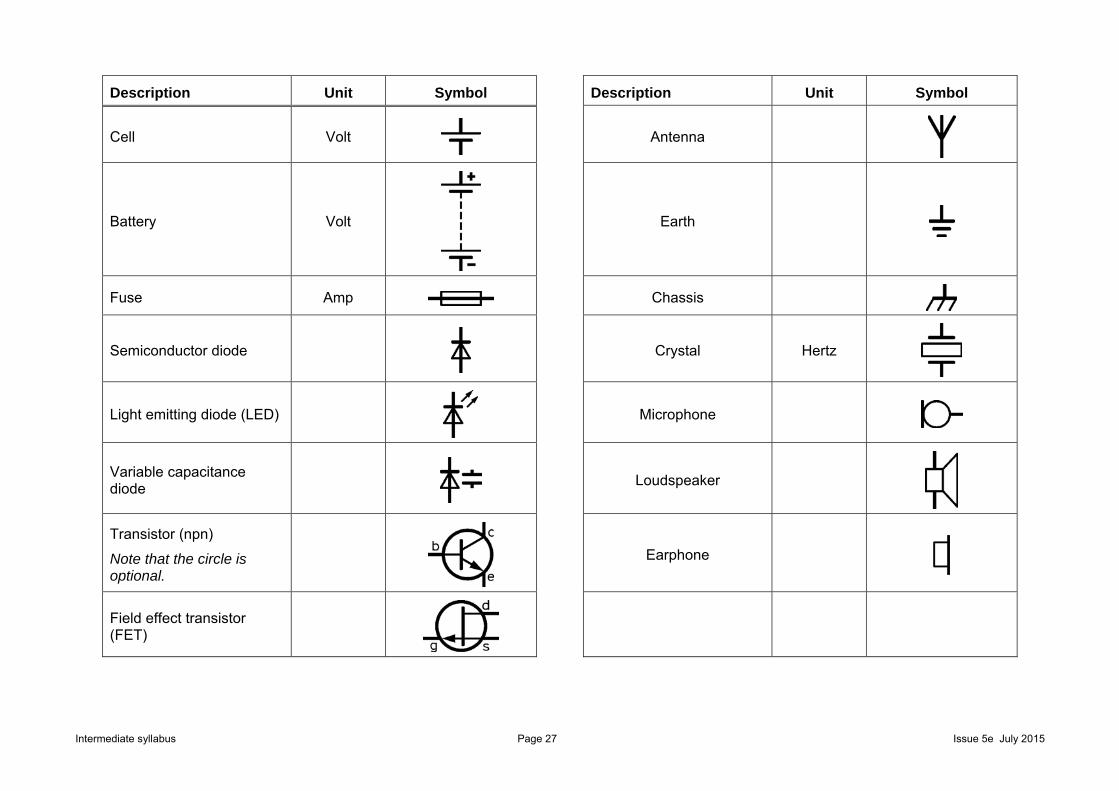
Note: The circuit symbols shown in Table 1 (page 23) will be used and candidates will be expected to recognise them.
3a Units of measurement and multiple/sub-multiple prefixes
3a.1 Recall the units and abbreviations for potential difference, current, power, resistance, capacitance, inductance and frequency. Understand the prefixes pico, nano, micro, milli, kilo, Mega and Giga.
3b Simple circuit theory
3b.1 Understand the relationship between power, potential difference and current. Manipulate the equation P=VI to find the unknown quantity given the other two. The prefixes milli and kilo may be used.
Recall that a current through a resistor results in a transfer of electrical energy to heat energy in the resistor.
Understand the relationship between potential difference, current and resistance. Manipulate the equation V=IR to find the unknown quantity given the other two. The prefixes milli and kilo may be used.
Understand circuits comprising series and parallel connections of resistors and cells. Calculate currents and potential differences in such circuits.
Calculate the combined resistance of two or three resistors in series. Calculate the effective resistance of two or three equal resistors in parallel.
3c Primary and Secondary Cells
3c.1 Understand that cells store energy in chemical form. Recall that a primary cell, once discharged, must be properly disposed of. Understand that a secondary cell is rechargeable as the chemical discharge process within it is reversible.
3d Capacitors
3d.1 Recall that a capacitor normally consists of two metal plates separated by an insulating material.
Intermediate syllabus Page 9 Issue 5e July 2015
S y l l a b u s A s s e s s m e n t O b j e c t i v e s
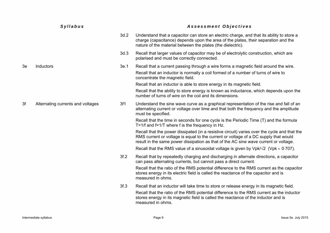
3d.2 Understand that a capacitor can store an electric charge, and that its ability to store a charge (capacitance) depends upon the area of the plates, their separation and the nature of the material between the plates (the dielectric).
3d.3 Recall that larger values of capacitor may be of electrolytic construction, which are polarised and must be correctly connected.
3e Inductors
3e.1 Recall that a current passing through a wire forms a magnetic field around the wire.
Recall that an inductor is normally a coil formed of a number of turns of wire to concentrate the magnetic field.
Recall that an inductor is able to store energy in its magnetic field.
Recall that the ability to store energy is known as inductance, which depends upon the number of turns of wire on the coil and its dimensions.
3f Alternating currents and voltages
3f1 Understand the sine wave curve as a graphical representation of the rise and fall of an alternating current or voltage over time and that both the frequency and the amplitude must be specified.
Recall that the time in seconds for one cycle is the Periodic Time (T) and the formula T=1/f and f=1/T where f is the frequency in Hz.
Recall that the power dissipated (in a resistive circuit) varies over the cycle and that the RMS current or voltage is equal to the current or voltage of a DC supply that would result in the same power dissipation as that of the AC sine wave current or voltage.
Recall that the RMS value of a sinusoidal voltage is given by Vpk/2 (Vpk 0707).
3f.2 Recall that by repeatedly charging and discharging in alternate directions, a capacitor can pass alternating currents, but cannot pass a direct current.
Recall that the ratio of the RMS potential difference to the RMS current as the capacitor stores energy in its electric field is called the reactance of the capacitor and is measured in ohms.
3f.3 Recall that an inductor will take time to store or release energy in its magnetic field.
Recall that the ratio of the RMS potential difference to the RMS current as the inductor stores energy in its magnetic field is called the reactance of the inductor and is measured in ohms.
Intermediate syllabus Page 10 Issue 5e July 2015
S y l l a b u s A s s e s s m e n t O b j e c t i v e s
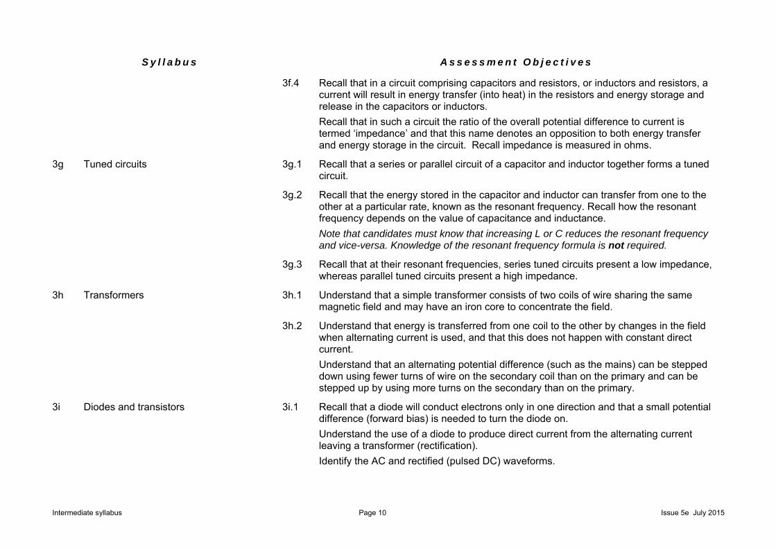
3f.4 Recall that in a circuit comprising capacitors and resistors, or inductors and resistors, a current will result in energy transfer (into heat) in the resistors and energy storage and release in the capacitors or inductors.
Recall that in such a circuit the ratio of the overall potential difference to current is termed ‘impedance’ and that this name denotes an opposition to both energy transfer and energy storage in the circuit. Recall impedance is measured in ohms.
3g Tuned circuits
3g.1 Recall that a series or parallel circuit of a capacitor and inductor together forms a tuned circuit.
3g.2 Recall that the energy stored in the capacitor and inductor can transfer from one to the other at a particular rate, known as the resonant frequency. Recall how the resonant frequency depends on the value of capacitance and inductance.
Note that candidates must know that increasing L or C reduces the resonant frequency and vice-versa. Knowledge of the resonant frequency formula is not required.
3g.3 Recall that at their resonant frequencies, series tuned circuits present a low impedance, whereas parallel tuned circuits present a high impedance.
3h Transformers
3h.1 Understand that a simple transformer consists of two coils of wire sharing the same magnetic field and may have an iron core to concentrate the field.
3h.2 Understand that energy is transferred from one coil to the other by changes in the field when alternating current is used, and that this does not happen with constant direct current.
Understand that an alternating potential difference (such as the mains) can be stepped down using fewer turns of wire on the secondary coil than on the primary and can be stepped up by using more turns on the secondary than on the primary.
3i Diodes and transistors
3i.1 Recall that a diode will conduct electrons only in one direction and that a small potential difference (forward bias) is needed to turn the diode on.
Understand the use of a diode to produce direct current from the alternating current leaving a transformer (rectification).
Identify the AC and rectified (pulsed DC) waveforms.

Intermediate syllabus Page 11 Issue 5e July 2015
S y l l a b u s A s s e s s m e n t O b j e c t i v e s
3i.2 Understand that in a rectifier circuit a capacitor can store a charge during the conducting part of the cycle and release it during the non-conducting part, providing a smoothing effect and a smoother DC output.
Identify the resulting waveforms.
3i.3 Recall that a light emitting diode (LED) is made from a material that will produce light when passing a suitable direct current.
3i.4 Recall that a variable capacitance diode behaves like a capacitor when reverse biased, and that the capacitance can be varied by changing the applied potential difference.
3i.5 Understand that a transistor is a three terminal device (emitter, base, collector) in which a small base current will control a larger collector current and this enables the transistor to be used as an amplifier.
Understand that the ratio of the collector current to the base current (IC/IB) is the current gain β of the transistor.
Note: the student is not required to recall transistor configurations. Circuits shown will be an npn transistor connected in common emitter mode.
3i.6 Understand that if the variation in the base current is large enough the collector current can be turned on and off and the transistor behaves as a switch.
3i.7 Recall that a transistor must be provided with the correct DC voltages and currents to allow it to function and that this is termed correct biasing.
Note that calculations are not required.
3i.8 Recall that a transistor can be used to generate audio and radio frequencies by maintaining the oscillations in a tuned or frequency selective circuit.
Distinguish between a crystal oscillator and a variable frequency oscillator (VFO) based on a tuned circuit.
Diagrams will show the Colpitts oscillator with the transistor in emitter follower mode. Students are not expected to recognise other types of oscillator.
3j Measurements
3j.1 Recall the purpose of a multimeter and understand how to set the meter to the correct range and polarity before connecting to the circuit.

Intermediate syllabus Page 12 Issue 5e July 2015
S y l l a b u s A s s e s s m e n t O b j e c t i v e s
3j.2 Understand the advantages and disadvantages of analogue and digital displays, and be able to read analogue and digital values.
3j.3 Understand that a voltmeter is always connected in parallel with a circuit component, and that an ammeter is always connected in series with a component.
3j.4 Understand that current in all parts of a series circuit has the same value and that the potential differences across components in parallel are the same.
3j.5 Understand the use of voltmeters and ammeters to determine the power applied to a circuit.
Recall that the RF output power (of an amplifier) is less than the DC input power.
4. Transmitters and Receivers
4a Simple block diagrams of a transmitter 4a.1 Recall and understand the block diagrams of CW, AM, SSB and FM transmitters.
4a.2 Understand the functions of: the microphone amplifier, AM/FM modulators, balanced modulator for SSB, side band filter, oscillator, power amplifier and low pass filter.
4b RF oscillators
4b.1 Recall and understand the relative advantages and disadvantages of a crystal oscillator and a VFO.
4b.2 Recall that the resonant frequency of the tuned circuit in a VFO determines the frequency of oscillation.
Intermediate syllabus Page 13 Issue 5e July 2015
S y l l a b u s A s s e s s m e n t O b j e c t i v e s
4b.3 Recall that the frequency stability of an oscillator can be improved by rigid mechanical construction, screening the oscillator enclosure, and using a regulated DC supply. Understand that a lack of stability (drift) may result in operation outside the amateur bands.
4b.4 Recall that most modern oscillators are digital synthesisers, which are very stable.
4c Mixers
4c.1 Recall that when two frequencies are mixed together, the mixing process generates new frequencies. Recall that these new frequencies are equal to the sum of and the difference between the original frequencies.
4d Modulation and sidebands
4d.1 Recall that, when audio frequencies are mixed with a radio frequency, the new frequencies that are generated are called sidebands. Recall that this process is called modulation.
4d.2 Recall that amplitude modulated signals contain two sidebands and the carrier.
4d.3 Understand that single sideband (SSB) is a form of amplitude modulation where one sideband and the carrier have been removed from the transmitted signal.
Understand that SSB is more efficient because power is not used to transmit the carrier and one sideband. Understand that a second advantage is that the transmitted signal takes up only half the bandwidth, e.g. 3 kHz not 6 kHz.
Recall that CW occupies the least bandwidth and that FM occupies the most bandwidth.
4d.4 Recall that data transmissions commonly use two or more audio tones to modulate the carrier.
4d.5 Recall that a variable capacitance diode can be used in an oscillator to produce frequency modulation (FM).
4e Transmitter interference
4e.1 Recall that excessive audio amplitude or excessive audio bandwidth into a modulator can cause excessive bandwidth or excessive FM deviation. Understand that this may result in interference to adjacent radio frequencies.
Intermediate syllabus Page 14 Issue 5e July 2015
S y l l a b u s A s s e s s m e n t O b j e c t i v e s
4e.2 Recall that oscillators, mixers and amplifiers can produce harmonics i.e. multiples of the fundamental frequency.
Recall that harmonics can cause interference to other amateur bands and other radio users.
4e.3 Recall that a filter is a device that blocks some frequencies and passes others.
Understand the effects of low-pass, band-pass and high-pass filters. Interpret their frequency/amplitude diagrams.
Understand that a low-pass filter and a band-pass filter can minimise the radiation of harmonics.
4e.4 Understand that too fast a rise and fall time of the transmitted RF envelope of a CW transmitter may cause excessive bandwidth (key clicks) and that this can be minimised by suitable filters in the keying stage.
4f Simple block diagram of receivers
4f.1 Understand the block diagrams of the crystal diode receiver, tuned radio frequency (TRF) or straight receiver and superhet receiver.
4f.2 Understand the functions of the RF amplifier, mixer, local oscillator, IF amplifier, demodulator (detector), and audio amplifier.
4g Intermediate frequency
4g.1 Recall that the intermediate frequency is the sum of or difference between the RF and local oscillator frequencies.
4h Frequency selection 4h.1 Understand that tuned circuits in RF and IF amplifiers select the wanted signal.
4i Detectors
4i.1 Understand how a diode detector will recover the audio from amplitude modulated signals. Understand that to generate the audio from CW signals a beat frequency oscillator (BFO) is used; for the recovery of single side band audio, a carrier insertion oscillator (CIO) and product detector is used; for the recovery of FM audio, a discriminator is used.
4i.2 Identify the waveforms produced in a diode AM detector.
4j AGC
4j.1 Understand that the automatic gain control (AGC) of a receiver operates by sensing the strength of the received signals at the detector and adjusting the gain of the IF and sometimes the RF amplifiers to keep the audio output level fairly constant.
Intermediate syllabus Page 15 Issue 5e July 2015
S y l l a b u s A s s e s s m e n t O b j e c t i v e s
5. Feeders and Antennas
5a Feeder basics 5a.1 Identify and recall the use of coaxial and twin feeders.
5a.2 Understand that equal and opposite currents flowing in a balanced feeder cause equal and opposite fields around the two conductors. Understand that these fields cancel out, but that nearby objects can cause an imbalance that makes the feeder radiate RF energy.
5a.3 Recall that in a correctly connected coaxial cable the RF field only exists within the cable and is not affected by objects outside the cable.
Note that correctly connected mean screen continuity through any plug and socket and connected to a balun or unbalanced load, not necessarily of 50Ω.
5a.4 Recall that feeders cause loss of signal strength on both transmit and receive. The longer the cable, the greater the loss.
Recall that twin feeder usually has lower loss than coaxial cable.
5a.5 Recall that loss is measured in dB. Be able to calculate the power delivered to an antenna for a given RF output and given feeder loss (in multiples of 3 dB and 10dB).
5b Feeder characteristic impedance
5b.1 Recall that feeders have a characteristic impedance which depends upon the diameter and spacing of the conductors.
Recall that this impedance determines the ratio of the RF RMS potential difference to the RF RMS current in a correctly terminated feeder.
Recall that for amateur use, 50 coaxial feeder is normally used; that coaxial cable for TV and satellite receivers has a different impedance, and that balanced feeder is commonly available from 75 to 600.
Note that correctly terminated means correctly connected with a resistive load equal to the cable characteristic impedance.
Intermediate syllabus Page 16 Issue 5e July 2015
S y l l a b u s A s s e s s m e n t O b j e c t i v e s
5c Antenna impedance
5c.1 Recall that the feed point impedance of an antenna is related to the dimensions of the antenna and the wavelength of the applied signal.
Recall that the current flowing into an antenna is related to the feed point impedance and the potential difference of the applied signal.
Recall that an antenna will only present the correct feed point impedance when fed with the frequency for which it is designed, and that a half-wave dipole has a feed point impedance of approximately 50 when used at its designed frequency.
Recall that if the feed point impedance of the antenna does not match that of the feeder, energy will be reflected back down the feeder; the proportion reflected depending upon the degree of mismatch.
5d Standing waves
5d.1 Understand that the signal reflected back down the feeder is not lost but will combine with the waves travelling up the feeder from the transmitter leading to the formation of standing waves.
Recall that the reflected signal will change the input impedance of the feeder so that it is no longer the characteristic impedance and the feeder will not then present the correct impedance to the transmitter.
5e Antenna tuning unit
5e.1 Recall that a transmitter is designed to transfer energy into a specific impedance.
Recall that an antenna tuner unit (ATU) can change the impedance presented to the transmitter and may also reduce harmonic radiation.
5f Antennas
5f.1 Understand the concept of an antenna polar diagram.
Identify the polar diagrams for the half–wave dipole and Yagi antennas.
Identify the directions of maximum and minimum radiation.
5f.2 Recall that the gain of an antenna is measured in dB, and understand how to calculate the Effective Radiated Power (ERP) for a known RF power and antenna gain (in multiples of 3 dB and 10dB).
5f.3 Recall that a three-element Yagi has a half-wave driven element, a reflector that is slightly longer than the driven element and a director that is slightly shorter than the driven element.
Recall that Yagi antennas may have more than one director.
Intermediate syllabus Page 17 Issue 5e July 2015
S y l l a b u s A s s e s s m e n t O b j e c t i v e s
5f.4 Recall that electromagnetic radiation comprises both an electrical field and a magnetic field.
Recall that the two fields are at right-angles to each other and that the direction of propagation is at right-angles to both fields.
Recall that it is the plane of polarisation of the electric field that defines polarisation of the wave.
5f.5 Recall that VHF and UHF signals will normally be received most effectively when the transmitter and the receiver have the same antenna polarisation and that this is less important at HF because the polarisation may change during ionospheric reflection.
5g Dummy loads 5g.1 Understand the use of a dummy load and its construction.
6. Propagation
Radio propagation basics
6a.1 Recall the basic structure of the ionosphere: D, E and F layers and their order. Understand that ionisation is caused mainly by ultraviolet rays from the sun.
6a.2 Recall that the level of ionisation changes with the time of day, the time of year, and according to the 11-year sunspot cycle. Understand that the sunspot number is an indicator of solar activity and that more sunspots give better HF propagation as a result of increased ionisation.
6a.3 Recall that reflection from the F layer is the main mode of HF propagation.
6a.4 Understand the meaning of ground wave, sky wave, skip distance and skip zone (dead zone).

Intermediate syllabus Page 18 Issue 5e July 2015
S y l l a b u s A s s e s s m e n t O b j e c t i v e s
6a.5 Recall that high atmospheric pressure can cause ducting in the troposphere, which increases the range of VHF and UHF signals.
Recall that the range of VHF signals can occasionally be significantly increased by reflection from highly ionised areas in the E layer (Sporadic E).
6a.6 Recall that VHF and UHF signals normally pass through the ionosphere, and at these frequencies propagation is within the troposphere situated below the ionosphere.
6a.7 Recall that snow, ice and heavy rain can attenuate signals at UHF and above.
6a.8 Recall and manipulate the formula v=f. Calculate frequency or wavelength given the other parameter.
For calculations, the velocity of radio waves will be given.
7. EMC
7a Basics of electromagnetic compatibility
7a.1 Understand that all electronic equipment is capable of radiating and absorbing radio frequency energy. Recall that the basic principle of electromagnetic compatibility is that apparatus should be able to function satisfactorily in its electromagnetic environment and without causing intolerable electromagnetic disturbance to other apparatus in that environment.
7a.2 Understand that transmitters in domestic environments may give rise to RF fields stronger than the agreed limits. Understand that transmitters in domestic environments are not ‘normal’ situations and special measures may have to be taken.
7a.3 Understand that new electronic equipment should meet the European EMC immunity requirements but that existing equipment and poorly installed equipment may not.

Intermediate syllabus Page 19 Issue 5e July 2015
S y l l a b u s A s s e s s m e n t O b j e c t i v e s
7b Good radio housekeeping
7b.1 Recall how to interconnect the transmitter, microphone, power supply, SWR meter and band or low pass filters, using appropriate cables, to minimise EMC problems.
7b.2 Understand that filters can be fitted in the leads from the power supply to the transmitter to help minimise RF energy entering the mains wiring.
7b.3 Recall what constitutes a good RF earth, its purpose and use.
7b.4 Recall how to use a suitable general coverage receiver to check for spurious and harmonic emissions from the station.
7b.5 Understand that siting a transmitting antenna close to mains wiring, TV or radio aerials and downleads is a potential problem exacerbated by the use of a loft or indoor transmitting antenna.
7c Interference sources and simple remedies
7c.1 Identify the forms of interference caused by amateur radio and other radio transmissions: voice on radio, telephone or audio systems. Recall that interference to digital televisions may cause the picture to freeze, pixelate, become jerky or disappear.
7c.2 Recall other sources of interference and their effects: arcing thermostats and vehicle ignition systems, electric motors in vacuum cleaners, fans, drills, sewing machines etc, computers and peripherals. Recall that this give rise to a buzz on sound radio.
7c.3 Recall that direct pick-up in affected devices tends to be independent of the transmitted frequency.
7c.4 Understand that masthead and downlead TV amplifiers are broadband, amplifying a wide range of frequencies, including amateur frequencies. Understand that this can result in overloading of the amplifier and/or the TV input.'
7c.5 Recall the use of ferrite ring filters for minimising unwanted RF on aerial downleads and mains leads to affected equipment.
Recall and understand the use of high-pass filters to reduce the level of HF and VHF amateur transmissions into TV systems.
Understand the use of mains filters to reduce RF, electric motor and thermostat interference to TV, radio, and audio systems.

Intermediate syllabus Page 20 Issue 5e July 2015
S y l l a b u s A s s e s s m e n t O b j e c t i v e s
7c.6 Understand that transmitting into a dummy load is a good test for any unwanted RF being conducted out of the transmitter along its power supply leads and into the mains.
7d Social issues of interference
7d.1 Understand that the station log will be of considerable assistance in dealing with complaints of interference, and that this is a good reason to keep a log of all transmissions.
7d.2 Understand the merits of the amateur and the complainant keeping a log of the instances of interference. Understand the merit of conducting tests in co-operation with the complainant in instances of interference.
7d.3 Recall that the RSGB and Ofcom produce information leaflets on EMC and interference.
Recall that advice is available from the RSGB EMC Committee and the role of local Ofcom officers in dealing with cases of interference.
8. Operating Practices and Procedures
8a Q codes
8a.1 Recall the meaning and the reason for use of the Q codes: QRL, QRM, QRN, QRP, QRT, QRZ, QSB, QSL, QSO, QSY, QTH.
8b Abbreviations
8b.1 Recall the meaning and the reason for use of the following: CQ, DE, DX, R, RST, SIG, UR, WX.
8c RST code
8c.1 Recall the meaning of the RST code, the number of divisions of each of the three items, and their order of merit.
8d Relative advantages of different modes.
8d.1 Understand the relative operational advantages of CW, SSB and FM
Intermediate syllabus Page 21 Issue 5e July 2015
S y l l a b u s A s s e s s m e n t O b j e c t i v e s
8e Other types of modulation
8e.1 Recall that types of modulation other than CW, SSB and FM are available to the Intermediate licensee (e.g. packet, PSK31, SSTV and FSTV).
8e.2 Recall that several types of transmission can be generated and received with the use of a personal computer and a suitable interface.
8f Good operating practices
8f.1 Recall that call sign prefixes, station locations and addresses can often be found in call books and from the Internet.
8f.2 Understand the concept of sending and receiving QSL cards.
8f.3 Recall common international call sign prefixes; EI (Eire), F (France), I (Italy), JA (Japan), PA (the Netherlands), VE (Canada), VK (Australia), W (USA), ZL (New Zealand).
8f.4 Understand that there is a competitive element in amateur radio: achievement awards, DX operation and contests. Recall their basic operating practices.
Achievement awards, e.g. for contacting country prefixes, ‘squares’ on a map or islands; normally confirmed by QSL cards.
Contests involve exchanging call signs and a serial number or location.
8g Satellites
8g.1 Recall that satellites orbit the Earth at heights above 150 km, and understand that amateur satellites are moving in relation to the Earth and will only be above the horizon at certain times.
8g.2 Recall that the up-link and down-link frequencies are generally in different amateur bands and that details are published by amateur organisations. Recall that the transmitting station must be able to receive both the up-link and down-link signals.
8g.3 Understand that amateur satellites can only be used when they are above the horizon at both the sending and receiving stations, and that the movement of the satellite will cause frequency variation (Doppler shift) on the received signal, which must be allowed for when selecting operating frequencies.
8g.4 Understand that satellites have a very limited power supply, derived from solar panels, and that excessive up-link power may result in wasteful and unfair use of the satellite’s power.

Intermediate syllabus Page 22 Issue 5e July 2015
S y l l a b u s A s s e s s m e n t O b j e c t i v e s
9. Safety
9a Soldering
9a.1 Recall that a soldering-iron stand must be used to avoid skin contact with the hot bit of the iron when not in use.
Understand that soldering work benches must be well ventilated to avoid inhalation of solder fumes, which can cause breathing problems particularly to asthmatics.
Understand that eye protection must be worn when soldering to prevent solder from splashing into the eyes.
9b Use of hand tools
9b.1 Understand that screwdrivers, drills, saws, and files must be handled with care to avoid cuts to the hands and face.
9b.2 Understand that any items being drilled, sawn or filed must be securely held in a vice or similar device to prevent them slipping or rotating.
9b.3 Understand that the chuck key must be removed before using a drill to prevent the key being ejected at high speed.
9b.4 Understand that using a centre punch will help prevent a drill bit slipping.
9b.5 Understand that eye protection must be worn when drilling to prevent eye damage from small metal particles (swarf).
9b.6 Understand the reasons why a bench-mounted pillar drill is safer than a hand-held drill.
9c Working at heights 9c.1 Recall that a ladder should be used at the correct angle (4:1 height-to-base ratio).
9c.2 Understand that ladders must be secured at the top or securely held at the bottom by an adult to prevent them slipping.
9c.3 Understand why it is important not to overreach from a ladder, to prevent falling off.
9c.4 Understand why a tool belt or similar device to carry tools should be used, and that it will help prevent falling objects. Understand the need to wear hard hats when working at height or when others are working at height.
9d Electricity
9d.1 Recall that a dangerous electric shock can result from antennas and ladders coming into contact with or attracting arcing from overhead lines.

Intermediate syllabus Page 23 Issue 5e July 2015
S y l l a b u s A s s e s s m e n t O b j e c t i v e s
9d.2 Understand that a fuse must be correctly rated for proper protection, and be able to select an appropriate fuse using the formula: current = power/230 where 230 is the nominal mains voltage.
9d.3 Understand that a residual current device (RCD) will give better protection against electric shock than relying solely on a conventional fuse (which only protects against excessive current) and earth system.
Note: The student should appreciate that an RCD will detect currents to earth of about 30mA whereas a fuse will only blow at several amps and only when the fault is a short circuit (L-N or L-E). The mechanics of RCD operation (differential current sensing) is not examinable.
9d.4 Understand that large or high-voltage capacitors can store dangerous electric charges and must be discharged before working on equipment.
9e RF
9e.1 Recall that the main health effect of exposure to electromagnetic radiation is heating of body tissue.
9e.2 Recall that guidance on safe levels of RF radiation is available from government and international bodies (HPA – Health Protection Agency and ICNIRP- International Committee on Non-Ionising Radiation Protection).
9e.3 Recall why it is unwise to look down a microwave frequency waveguide or to stand close to or in front of high-gain antennas as they may be in use.
10. Construction
10a Recognise components
10a.1 Identify resistors, capacitors including fixed, variable and electrolytic types, inductors, transformers, diodes, transistors, integrated circuits, crystals, microphones and loudspeakers.
10b Soldering basics
10b.1 Understand that soldering is a method of joining metal wires and components using a hot soldering iron to melt the solder.
10b.2 Recall that many solders contain a flux to help the solder to flow and to prevent a layer of oxide forming on the surfaces to be joined.
Intermediate syllabus Page 24 Issue 5e July 2015
S y l l a b u s A s s e s s m e n t O b j e c t i v e s
10b.3 Recall that some metals are easy to solder and some are difficult.
10b.4 Understand that the tip of the soldering iron has to be cleaned to help remove any oxide and then ‘tinned’ to prevent the oxide re-forming and to improve the conduction of heat to the joint.
Recall the reason for tinning wires prior to soldering.
10b.5 Recall that it is necessary to make joints reasonably quickly to avoid damage to components, and that most construction faults stem from poor (dry) joints.
10c Colour code
10c.1 Recall the resistor colour code, colours 0 to 9 with gold as multiplier. Recall silver (10%) and gold (5%) as tolerance bands. Identify the value of a resistor between 1 and 9M from the E12 series.
10d Practical skills
Each of the objectives in this section 10d should be read as if they were prefaced with the words “Satisfy the assessors that the candidate is properly able to”
* 10d.1 Read the colour code bands on a number of different resistors and confirm their value
by measurement.
* 10d.2 Demonstrate the ability to make good soldered joints.
* 10d.3 Construct a simple circuit containing a battery, resistor, LED, lamp and switch.
* 10d.4 Measure potential differences and currents in a simple circuit.
* 10d.5 Demonstrate that a diode will only conduct in one direction in a simple DC circuit.
* 10d.6 Demonstrate that a transistor can be used as a switch in a simple DC circuit.
* 10d.7 Fit a suitable RF connector (PL259, BNC or N-type) to a piece of coaxial cable.
* 10d.8 Fit a 13A plug to a piece of three-core mains cable.

Intermediate syllabus Page 25 Issue 5e July 2015
S y l l a b u s A s s e s s m e n t O b j e c t i v e s
10e Construction
*
10e.1 Construct a simple amateur radio related project (e.g. direct conversion receiver, crystal calibrator, ‘grid’ dip meter, ATU and SWR meter, Morse oscillator, audio amplifier) either from a pre-prepared kit or from a published or personal design.
Construction may be carried out either within a course or elsewhere, but the assessor must be satisfied that the bulk of the work is that of the candidate.
10f Simple frequency calibration
*
10f.1 Calibrate a variable frequency oscillator (VFO) employing an adjustable tuned circuit. Calibration to show the relevant amateur band edges.
The VFO may form part of the project to satisfy 10e.1, or be part of a previously constructed project or provided by the assessor.
* Items shown with an asterisk above are assessed as a practical demonstration by the candidate and ‘signed off’ by the assessor on the Record of Achievement.
Note: If the candidate is disabled in any way that reasonably prevents the carrying out of any practical procedure, he or she may talk another person through the task or describe it to the assessor.
Intermediate syllabus Page 26 Issue 5e July 2015
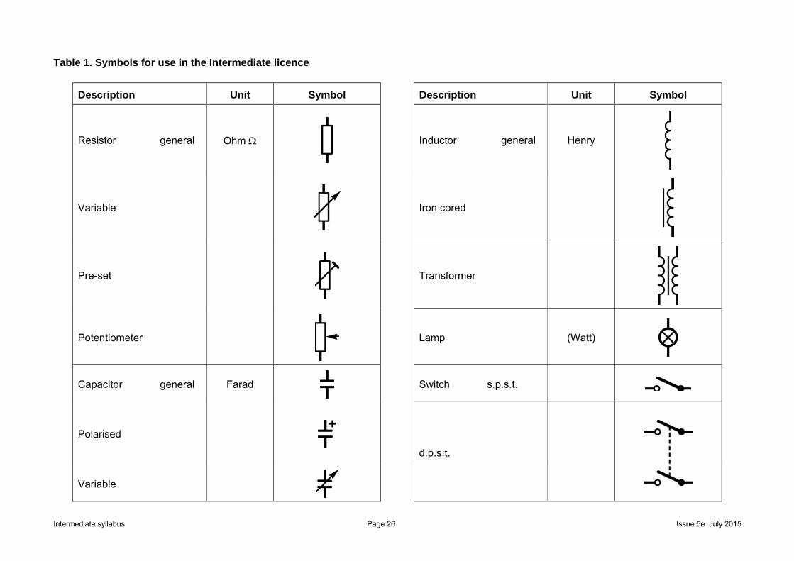
Table 1. Symbols for use in the Intermediate licence
Description Unit Symbol Description Unit Symbol
Resistor general Ohm
Inductor general Henry
Variable
Iron cored
Pre-set
Transformer
Potentiometer
Lamp (Watt)
Capacitor general Farad
Switch s.p.s.t.
Polarised
d.p.s.t.
Variable
Intermediate syllabus Page 27 Issue 5e July 2015
Description Unit Symbol Description Unit Symbol
Cell Volt
Antenna
Battery Volt
Earth
Fuse Amp Chassis
Semiconductor diode
Crystal Hertz
Light emitting diode (LED)
Microphone
Variable capacitance diode
Loudspeaker
Transistor (npn)
Note that the circle is optional.
Earphone
Field effect transistor (FET)
Intermediate Syllabus Page 28 Issue 5e
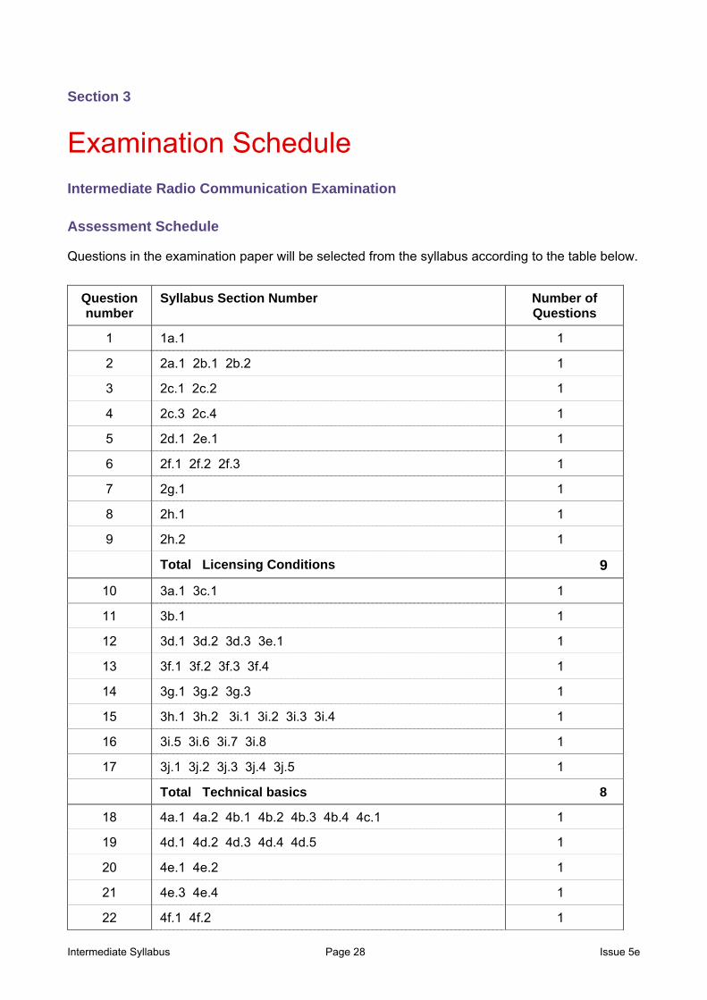
Section 3
Examination Schedule
Intermediate Radio Communication Examination
Assessment Schedule
Questions in the examination paper will be selected from the syllabus according to the table below.
Question number
Syllabus Section Number Number of Questions
1 1a.1 1
2 2a.1 2b.1 2b.2 1
3 2c.1 2c.2 1
4 2c.3 2c.4 1
5 2d.1 2e.1 1
6 2f.1 2f.2 2f.3 1
7 2g.1 1
8 2h.1 1
9 2h.2 1
Total Licensing Conditions 9
10 3a.1 3c.1 1
11 3b.1 1
12 3d.1 3d.2 3d.3 3e.1 1
13 3f.1 3f.2 3f.3 3f.4 1
14 3g.1 3g.2 3g.3 1
15 3h.1 3h.2 3i.1 3i.2 3i.3 3i.4 1
16 3i.5 3i.6 3i.7 3i.8 1
17 3j.1 3j.2 3j.3 3j.4 3j.5 1
Total Technical basics 8
18 4a.1 4a.2 4b.1 4b.2 4b.3 4b.4 4c.1 1
19 4d.1 4d.2 4d.3 4d.4 4d.5 1
20 4e.1 4e.2 1
21 4e.3 4e.4 1
22 4f.1 4f.2 1

Intermediate Syllabus Page 29 Issue 5e
Question number
Syllabus Section Number Number of Questions
23 4g.1 4h.1 1
24 4i.1 4i.2 4j.1 1
Total Transmitters and Receivers 7
25 5a.1 5a.2 5a.3 5a.4 5a.5 5b.1 1
26 5c.1 5d.1 5e.1 1
27 5f.1 5f.2 5f.3 5f.4 5f.5 5g.1 1
Total Feeder and Antenna 3
28 6a.1 6a.2 6a.3 6a.4 1
29 6a.5 6a.6 6a.7 1
30 6a.8 1
Total Propagation 3
31 7a.1 7a.2 7a.3 1
32 7b.1 7b.2 7b.3 7b.4 7b.5 1
33 7c.1 7c.2 7c.3 1
34 7c.4 7c.5 7c.6 1
35 7d.1 7d.2 7d.3 1
Total EMC 5
36 8a.1 8b.1 8c.1 1
37 8 d.1 8e.1 8e.2 1
38 8f.1 8f.2 8f.3 8f.4 1
39 8g.1 8g.2 8g.3 8g.4
Total Operating Practices and Procedures 4
40 9a.1 1
41 9b.1 9b.2 9b.3 9b.4 9b.5 9b.6 1
42 9c.1 9c.2 9c.3 9c.4 1
43 9d.1 9d.2 9d.3 9d.4 9e.1 9e.2 9e.3 1
Total Safety 4
44 10a.1 10b.1 10b.2 10b.3 10b.4 10b.5 1
45 10c.1 1
Total Construction 2
Total Number of Questions 45