for evolution plc system - pryco.com · manual for evolution plc system pryco, inc. p. o. box 108...
TRANSCRIPT
PRYCO, INC. EVOLUTION—OPERATIONS MANUAL
OPERATIONS
AND
MAINTENANCE
MANUAL
For
EVOLUTION
PLC SYSTEM
PRYCO, INC. P. O. BOX 108 Mechanicsburg, IL 62545
Telephone: 217 / 364-4467 Fax: 217 / 364-4494

PRYCO, INC. EVOLUTION—OPERATIONS MANUAL
WHAT TO DO FIRST
Upon receiving your new tank with PLC system equipment, always check for physical signs of damages before signing the bill of lading. Inspect for possible damage that might have occurred during shipment. All products are inspected at point of shipment to ensure they are free of any defects. Dropping and other rough handling in transit could place stress that will result in a failure. Check to ensure the system equipment arrives in good condition.
THEN
Always have the fuel system installed by trained, authorized personnel. Record your model and serial numbers here and save this manual. The model and serial numbers are located on the tag inside the electrical enclosure cover. Model: Install Date:
Serial Number
Refer to this serial number whenever you contact the factory:
Pryco, Inc. Telephone: 217-364-6647 3rd and Garvey Sts Fax: 217-364-4494 P.O. Box 108 Email: [email protected] Mechanicsburg, IL 62545
PLC MAINTENANCE
The PLC components , including the touch screen, generally need no maintenance ex-cept for an occasional dusting or light cleaning. In a dusty environment, canned aerosol air, as is used for computer keyboards, etc., should be used to blow dust out of component vents. The LCD touch screen will magnetically attract airborne particles and fingerprints. Do not use any abrasive cleaner or towels to clean the LCD screen—it will be permanently scratched. A dry soft cloth should be used. For more stubborn dirt, commercially available aerosol cleaners (for LCD/Plasma television, computer LCD monitor screen, etc.) and a soft cloth should work. Never use a petroleum-based solvent.
Page 2
PRYCO, INC. EVOLUTION—OPERATIONS MANUAL
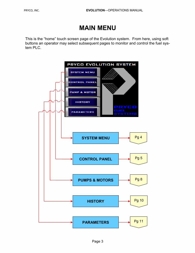
MAIN MENU
SYSTEM MENU
Pg 5 CONTROL PANEL
PUMPS & MOTORS
HISTORY
PARAMETERS
Page 3
This is the “home” touch screen page of the Evolution system. From here, using soft buttons an operator may select subsequent pages to monitor and control the fuel sys-tem PLC.
Pg 4
Pg 8
Pg 10
Pg 11
PRYCO, INC. EVOLUTION—OPERATIONS MANUAL
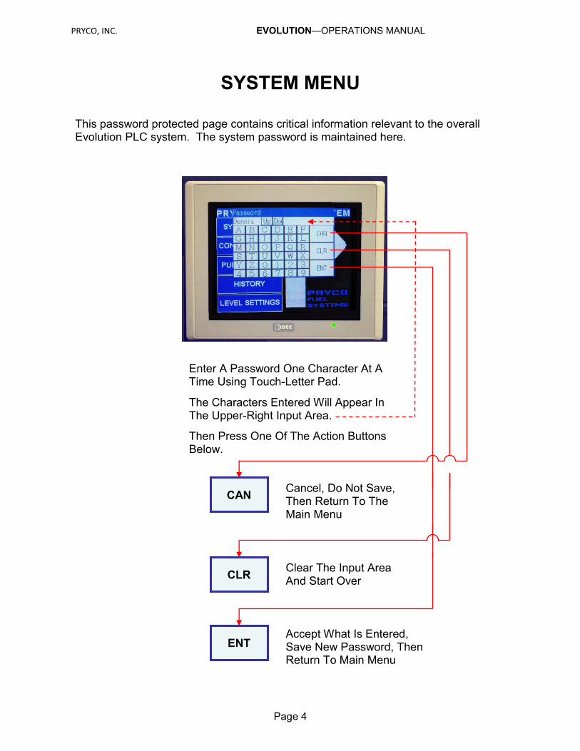
SYSTEM MENU
CAN
CLR
ENT
Enter A Password One Character At A Time Using Touch-Letter Pad.
The Characters Entered Will Appear In The Upper-Right Input Area.
Then Press One Of The Action Buttons Below.
Cancel, Do Not Save, Then Return To The Main Menu
Clear The Input Area And Start Over
Accept What Is Entered, Save New Password, Then Return To Main Menu
Page 4
This password protected page contains critical information relevant to the overall Evolution PLC system. The system password is maintained here.

PRYCO, INC. EVOLUTION—OPERATIONS MANUAL
CONTROL PANEL Graphics Description
(Continues Next Page)
Page 5
BACK TO MAIN MENU Soft Push Button (Page 3)
NUMBER GALLONS OF FUEL IN TANK Linear Display
PERCENT FULL Linear Display
GRAPHIC DISPLAYS – COL. 1 Actions/Alarms (See Page 6 &7)
This is the monitoring screen page. Each monitored feature that is available to the system is represented here as a solid illuminated lamp. If a feature becomes “active” the lamp graphic flashes. An operator can determine at a glance if the system is op-erating normally.
Two yellow linear-scaled graphics report fuel level in “percent full” and in gallons. A digital readout of number of gallons (blue) is shown above these areas.
NUMBER GALLONS OF FUEL TANK Digital Display

PRYCO, INC. EVOLUTION—OPERATIONS MANUAL
CONTROL PANEL Graphics Actions/Alarms Display – Column 1
(Continues Next Page)
Page 6
A single pump and motor (Supply Pump) or the first pump and motor (Supply Pump #1) of a duplex system is installed run-ning. (See page 8 to determine how the duplex system is set to operate.)
A single pump and motor (Supply Pump) or the first pump and motor (Supply Pump #1) of a duplex system is installed. (See page 8 to determine how the duplex system is set to op-erate.)
The second pump and motor (Supply Pump #2) of a duplex system is running. (See page 8 to determine how the duplex system is set to operate.)
A second pump and motor (Supply Pump #2) of a duplex system is installed. (See page 8 to determine how the duplex system is set to operate.)
The fuel level has exceeded the predetermined high fuel level—normally 103% capacity. Supply pump(s) and motor(s) are shut-down.
The “Critical High” fuel monitor is functioning properly.
A leak in the secondary contain-ment area is detected.
The “Rupture Alarm” monitor is functioning properly.
FLASHING LIT SOLID
Correct the abnor-mal condition that is causing a flashing red LED graphic. The system will au-tomatically restore the flashing LED graphic to its solid state.
Red Graphic LED Lamps lit solid gen-erally indicates nor-mal operation
The “Alarm Silence Switch” The alarm silence switch is for silencing alarm horn when or-dered with Opt 223/224.
The “HOA Switch(s) ” is in the “AUTO” position.
The HOA switch(s) is not in the “AUTO” postion.
PRYCO, INC. EVOLUTION—OPERATIONS MANUAL
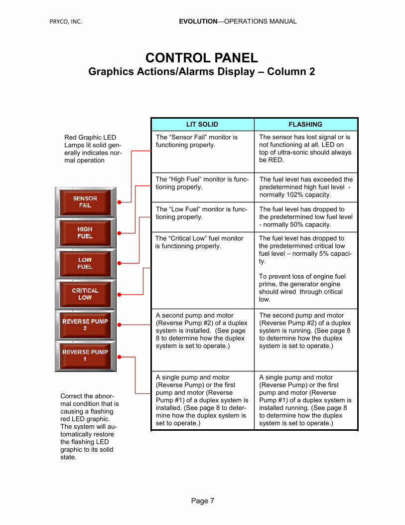
CONTROL PANEL Graphics Actions/Alarms Display – Column 2
Page 7
A single pump and motor (Reverse Pump) or the first pump and motor (Reverse Pump #1) of a duplex system is installed running. (See page 8 to determine how the duplex system is set to operate.)
A single pump and motor (Reverse Pump) or the first pump and motor (Reverse Pump #1) of a duplex system is installed. (See page 8 to deter-mine how the duplex system is set to operate.)
The second pump and motor (Reverse Pump #2) of a duplex system is running. (See page 8 to determine how the duplex system is set to operate.)
A second pump and motor (Reverse Pump #2) of a duplex system is installed. (See page 8 to determine how the duplex system is set to operate.)
The fuel level has dropped to the predetermined low fuel level - normally 50% capacity.
The “Low Fuel” monitor is func-tioning properly.
FLASHING LIT SOLID
Correct the abnor-mal condition that is causing a flashing red LED graphic. The system will au-tomatically restore the flashing LED graphic to its solid state.
Red Graphic LED Lamps lit solid gen-erally indicates nor-mal operation
The “Critical Low” fuel monitor is functioning properly.
The fuel level has dropped to the predetermined critical low fuel level – normally 5% capaci-ty. To prevent loss of engine fuel prime, the generator engine should wired through critical low.
The “High Fuel” monitor is func-tioning properly.
The fuel level has exceeded the predetermined high fuel level - normally 102% capacity.
The “Sensor Fail” monitor is functioning properly.
The sensor has lost signal or is not functioning at all. LED on top of ultra-sonic should always be RED.
PRYCO, INC. EVOLUTION—OPERATIONS MANUAL
PUMPS & MOTORS
(Continues Next Page)
Page 8
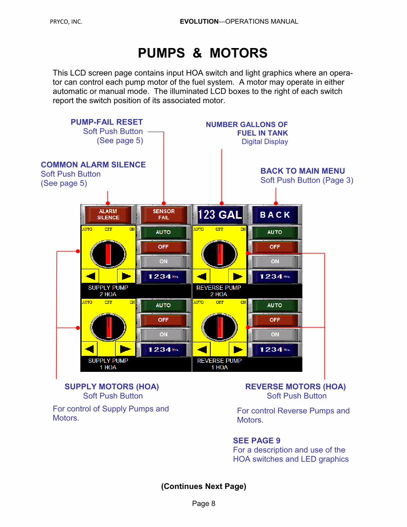
NUMBER GALLONS OF FUEL IN TANK Digital Display
PUMP-FAIL RESET Soft Push Button
(See page 5)
COMMON ALARM SILENCE Soft Push Button (See page 5)
SEE PAGE 9 For a description and use of the HOA switches and LED graphics
SUPPLY MOTORS (HOA) Soft Push Button
For control of Supply Pumps and Motors.
This LCD screen page contains input HOA switch and light graphics where an opera-tor can control each pump motor of the fuel system. A motor may operate in either automatic or manual mode. The illuminated LCD boxes to the right of each switch report the switch position of its associated motor.
BACK TO MAIN MENU Soft Push Button (Page 3)
REVERSE MOTORS (HOA) Soft Push Button
For control Reverse Pumps and Motors.
PRYCO, INC. EVOLUTION—OPERATIONS MANUAL
PUMPS & MOTORS HOA Switches and LED Displays
Page 9
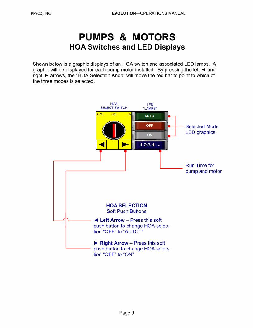
Selected Mode LED graphics
HOA SELECTION Soft Push Buttons
Shown below is a graphic displays of an HOA switch and associated LED lamps. A graphic will be displayed for each pump motor installed. By pressing the left ◄ and right ► arrows, the “HOA Selection Knob” will move the red bar to point to which of the three modes is selected.
◄ Left Arrow – Press this soft push button to change HOA selec-tion “OFF” to “AUTO” “ ► Right Arrow – Press this soft push button to change HOA selec-tion “OFF” to “ON”
HOA SELECT SWITCH
LED “LAMPS”
Run Time for pump and motor
PRYCO, INC. EVOLUTION—OPERATIONS MANUAL
HISTORY Activity Log Display
Page 10
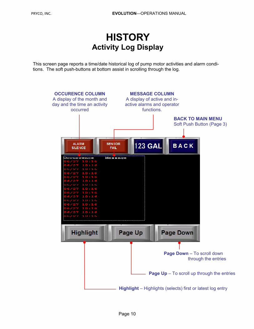
This screen page reports a time/date historical log of pump motor activities and alarm condi-tions. The soft push-buttons at bottom assist in scrolling through the log.
OCCURENCE COLUMN A display of the month and day and the time an activity
occurred
MESSAGE COLUMN A display of active and in-active alarms and operator
functions.
BACK TO MAIN MENU Soft Push Button (Page 3)
Highlight – Highlights (selects) first or latest log entry
Page Up – To scroll up through the entries
Page Down – To scroll down through the entries

PRYCO, INC. EVOLUTION—OPERATIONS MANUAL
PARAMETERS
Page 11
This password-protected page contains level settings at which specified actions (pump motor on/off, high low fuel levels, etc.) are to begin. Optional Pump fail timers are also displayed for user defined time. This allows dynamic fine tuning at the job sight.
DESCRIPTION COLUMN (ACTIVITY LEVEL SETTING) A display of the pump motor
activity level setting
LEVEL SETTING COLUMN Entry areas (using display
touch keypad) that indicates the distance, in inches, that
an activity begins
BACK TO MAIN MENU Soft Push Button (Page 3)
MODBUS COMM SETTINGS Displays communication port set-
ting for Modbus.
SLAVE NUMBER (MODBUS SLAVE NUMBER)
Using display touch keypad allows user to change slave number.
PRYCO, INC. EVOLUTION—OPERATIONS MANUAL
WARRANTY
PRYCO, INC.
All sales by PRYCO, INC., are subject to the following terms and conditions as its Warranties:
1. WARRANTIES – Seller warrants the Goods will be as described on the face hereof, will be free from any defects in material and workmanship at the time of delivery and will be manufactured in accordance with the Fair Labor Standard Act of 1938, as amended. SELLER MAKES NO OTHER WARRANTY, EX-PRESS OR IMPLIED, AND ALL IMPLIED WARRANTIES, INCLUDING WITHOUT LIMITATION, IM-PLIED WARRANTIES OF MERCHANTABILITY AND FITNESS FOR A PARTICULAR PURPOSE, ARE HEREBY DISCLAIMED. In order to assert a claim for breach of warranty, Buyer must contact Seller within one (1) year from date of sale determined by invoice date and which Seller’s examination shall disclose to its satisfaction to thus defective. This remedy is agreed by Buyer and Seller to constitute a sole and exclusive remedy and all sales are made subject to the conditions that Seller is not liable for consequential damage or for personal injuries of Buyer or its agents thereof. Seller will not warrant in-stallation of Goods by Buyer or its agents. Seller will not be responsible for service, labor or other ex-penses incurred by buyer, their customers or agent for replacement of defective goods.
2. EXCLUSIVE REMEDY – The exclusive remedy of the Buyer for any breach of the warranties set out in Section (7) will be, in Seller’s sole discretion, the replacement or repair of the Defective Goods provided Buyer pays shipping charges for return of such Goods to Seller.
3. LIMITATION OF DAMAGE – In the event of a breach hereof, Seller will not under any circumstance be liable for consequential or incidental damage or expenses of the Buyer including without limitation lost profits, whether or not the Seller has been advised of the same.
4. BUYER’S INDEMNITY – The Buyer shall indemnify and hold Seller harmless from and against any and all losses, damages and expenses (including attorneys’ fees and other costs of defending any action) that the Seller may sustain or incur as a result of any claim of negligence, breach of implied warranty or strict liability by the Buyer, its successors, agents, assigns or customers, whether direct or indirect, in connection with the use of the Goods.
PRYCO, INC. P. O. BOX 108
Mechanicsburg, IL 62545
Telephone: 217 / 364-4467
Fax: 217 / 364-4494
Web Site: www.Pryco.com
Email: [email protected]