for cooling systems sizing and startup procedures
TRANSCRIPT

Building Science Corporation
Sizing and Startup Proceduresfor Cooling Systems
by
Armin Rudd
Building Science Consortium
USDOE Building America Program
for
EEBA 2001 Excellence in Building Conference
Orlando, Florida
Friday, 26 October 2001, 10:05 - 11:30 am
PR-0109: Sizing and Startup Procedures for Cooling Systems 2 of 29

Building America program
Production homebuilderpartners:Pulte, Centex, Del Webb, KB, Artistic, T&C, Sturbridge
Building Science Consortium
October 2001
PR-0109: Sizing and Startup Procedures for Cooling Systems 3 of 29

Building Science Corporation
PR-0109: Sizing and Startup Procedures for Cooling Systems 4 of 29

High performance building envelopesHigh performance building envelopesdeserve high performance comfortdeserve high performance comfortconditioning systems.conditioning systems.
Building Science Consortium
October 2001
Especially for refrigerant based coolingEspecially for refrigerant based coolingsystems, proper sizing and startupsystems, proper sizing and startupprocedures are critical.procedures are critical.
PR-0109: Sizing and Startup Procedures for Cooling Systems 5 of 29

•• Cooling system sizing proceduresCooling system sizing procedures•• entire system and room-by-room flowsentire system and room-by-room flows
Building Science Consortium
October 2001
•• Duct and transfer air sizing proceduresDuct and transfer air sizing procedures•• supply and return plenumssupply and return plenums•• duct run-outsduct run-outs•• transfer grilles and jump ductstransfer grilles and jump ducts
•• Refrigeration system set and startupRefrigeration system set and startupproceduresprocedures•• line-set install, connecting units, leak testingline-set install, connecting units, leak testing•• evacuation, charging, checking charge and airflowevacuation, charging, checking charge and airflow
Main OutlineMain Outline
PR-0109: Sizing and Startup Procedures for Cooling Systems 6 of 29

Cooling system sizing procedures:Cooling system sizing procedures:Entire systemEntire system
Building Science Consortium
October 2001
•• Computerized ACCA Manual J approachComputerized ACCA Manual J approach•• Elite Software - RHVACElite Software - RHVAC•• Wrightsoft - Right JWrightsoft - Right J•• othersothers
•• need to handle especially carefully:need to handle especially carefully:–– infiltration infiltration–– ventilation ventilation–– glazing, conversion of SHGC to SC glazing, conversion of SHGC to SC–– temperature swing multiplier temperature swing multiplier
SC.SHGC 860=
PR-0109: Sizing and Startup Procedures for Cooling Systems 7 of 29

Building Science Corporation
Intermittent Ventilation Operation
• Sizing
– intermittent flow equals constant flow reducedby low background infiltration amount whenblower is not on, all divided by duty cyclefraction
&( & ( ( )))
IV f
fin
co
=− −
601
PR-0109: Sizing and Startup Procedures for Cooling Systems 8 of 29
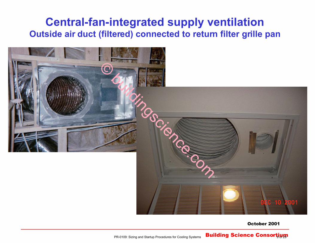
Central-fan-integrated supply ventilationOutside air duct (filtered) connected to return filter grille pan
Building Science Consortium
October 2001
© buildingscience.com
PR-0109: Sizing and Startup Procedures for Cooling Systems 9 of 29

Cooling system sizing procedures:Cooling system sizing procedures:Entire system (cont.)Entire system (cont.)
Building Science Consortium
October 2001
•• Complete house model with front facing north, thenComplete house model with front facing north, thenrotate front of house to east, south, and westrotate front of house to east, south, and west
•• Size system to 100% of total load at worst orientationSize system to 100% of total load at worst orientationfor subdivisionsfor subdivisions
•• Choose equipment so that total cooling capacityChoose equipment so that total cooling capacitymatches the total cooling load at the outdoor designmatches the total cooling load at the outdoor designtemperaturetemperature•• nominal ratings are for 95 F outdoor temperaturenominal ratings are for 95 F outdoor temperature•• most unused latent capacity converts to sensiblemost unused latent capacity converts to sensible
PR-0109: Sizing and Startup Procedures for Cooling Systems 10 of 29

Cooling system sizing procedures:Cooling system sizing procedures:Room-by-room air flowRoom-by-room air flow
Building Science Consortium
October 2001
•• For any given subdivision model, average the computedFor any given subdivision model, average the computedcfm’s for each room across all four cardinal orientationscfm’s for each room across all four cardinal orientations
•• This gives maximum flexibility to balance flowsThis gives maximum flexibility to balance flowsfrom the middle rather than the extremesfrom the middle rather than the extremes
•• Choose supply registers that have multiple adjustableChoose supply registers that have multiple adjustablecurved blades in front to direct air flow, and flat bladescurved blades in front to direct air flow, and flat bladeswith a single-lever control in back to balance flowwith a single-lever control in back to balance flow
PR-0109: Sizing and Startup Procedures for Cooling Systems 11 of 29

Duct sizingDuct sizing
Building Science Consortium
October 2001
•• Using the computerized ACCA Manual J approach,Using the computerized ACCA Manual J approach,apply the following air velocity constraints to getapply the following air velocity constraints to getappropriate duct sizing:appropriate duct sizing:
•• supply plenum: max supply plenum: max 750750 ft/min ft/min•• supply run-outs: max supply run-outs: max 500500 ft/min ft/min•• return grille: max return grille: max 350350 ft/min ft/min (use 80% free area or actual)(use 80% free area or actual)
•• return duct: max return duct: max 500500 ft/min ft/min
fraction area free
ft/min speed,air
/min3ft flow, c volumetri
2ft area, :where
=
=
=
=
?=
f
v
Q
A
fv
QA
&
&
PR-0109: Sizing and Startup Procedures for Cooling Systems 12 of 29
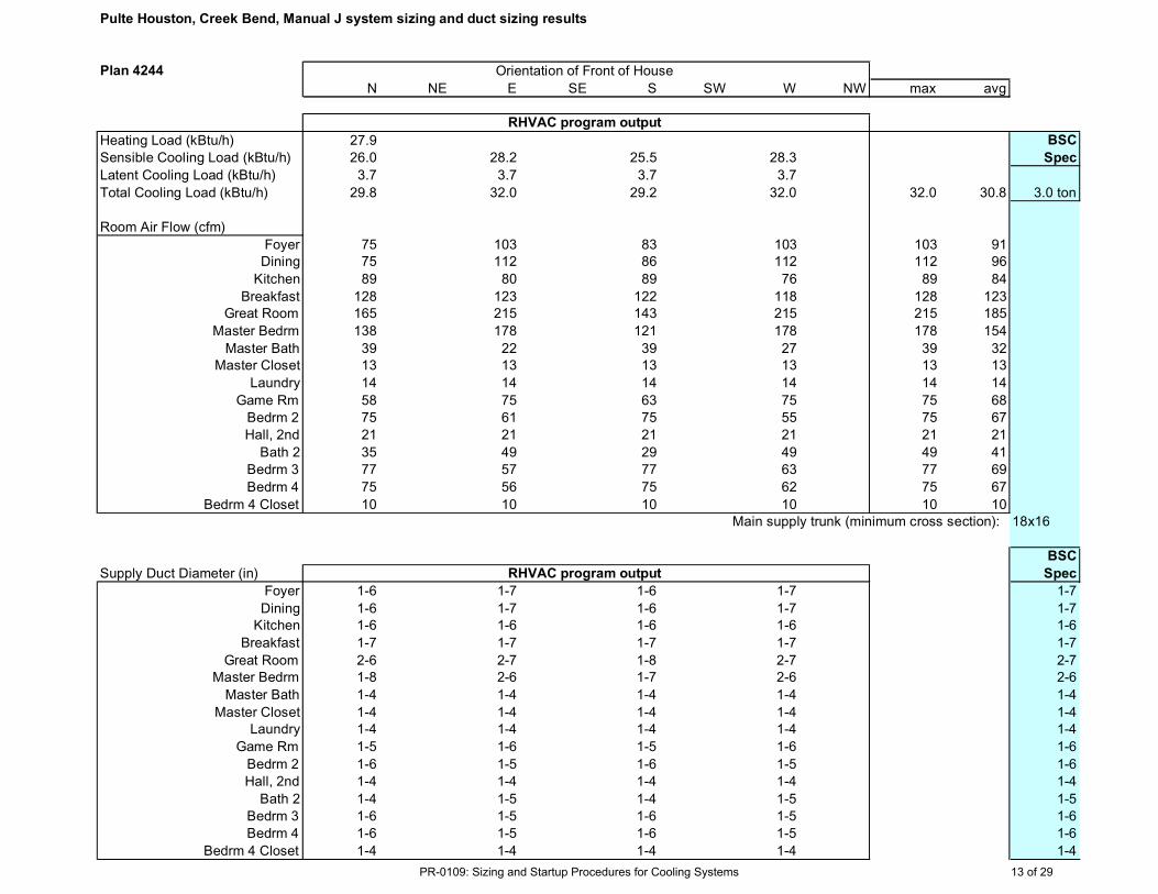
Pulte Houston, Creek Bend, Manual J system sizing and duct sizing results
Plan 4244
N NE E SE S SW W NW max avg
Heating Load (kBtu/h) 27.9 BSC
Sensible Cooling Load (kBtu/h) 26.0 28.2 25.5 28.3 Spec
Latent Cooling Load (kBtu/h) 3.7 3.7 3.7 3.7
Total Cooling Load (kBtu/h) 29.8 32.0 29.2 32.0 32.0 30.8 3.0 ton
Room Air Flow (cfm)
Foyer 75 103 83 103 103 91Dining 75 112 86 112 112 96
Kitchen 89 80 89 76 89 84
Breakfast 128 123 122 118 128 123Great Room 165 215 143 215 215 185
Master Bedrm 138 178 121 178 178 154
Master Bath 39 22 39 27 39 32Master Closet 13 13 13 13 13 13
Laundry 14 14 14 14 14 14
Game Rm 58 75 63 75 75 68
Bedrm 2 75 61 75 55 75 67
Hall, 2nd 21 21 21 21 21 21
Bath 2 35 49 29 49 49 41
Bedrm 3 77 57 77 63 77 69
Bedrm 4 75 56 75 62 75 67
Bedrm 4 Closet 10 10 10 10 10 10Main supply trunk (minimum cross section): 18x16
BSC
Supply Duct Diameter (in) Spec
Foyer 1-6 1-7 1-6 1-7 1-7
Dining 1-6 1-7 1-6 1-7 1-7Kitchen 1-6 1-6 1-6 1-6 1-6
Breakfast 1-7 1-7 1-7 1-7 1-7
Great Room 2-6 2-7 1-8 2-7 2-7Master Bedrm 1-8 2-6 1-7 2-6 2-6
Master Bath 1-4 1-4 1-4 1-4 1-4
Master Closet 1-4 1-4 1-4 1-4 1-4Laundry 1-4 1-4 1-4 1-4 1-4
Game Rm 1-5 1-6 1-5 1-6 1-6
Bedrm 2 1-6 1-5 1-6 1-5 1-6
Hall, 2nd 1-4 1-4 1-4 1-4 1-4
Bath 2 1-4 1-5 1-4 1-5 1-5
Bedrm 3 1-6 1-5 1-6 1-5 1-6
Bedrm 4 1-6 1-5 1-6 1-5 1-6
Bedrm 4 Closet 1-4 1-4 1-4 1-4 1-4
Orientation of Front of House
RHVAC program output
RHVAC program output
PR-0109: Sizing and Startup Procedures for Cooling Systems 13 of 29

Transfer duct/grille sizingTransfer duct/grille sizing
Building Science Consortium
October 2001
•• Calculate free area required to get proper transferCalculate free area required to get proper transferair flow to avoid more than 3 Pa pressurizationair flow to avoid more than 3 Pa pressurization
•• For jump ducts, don’t use less than 6” diameter, most For jump ducts, don’t use less than 6” diameter, mostmaster suites will need 10” to 12” diametermaster suites will need 10” to 12” diameter
853.1307.1
QQA
&&==
where: A = area in square inches
Q& = air flow rate (ft3/min)
PR-0109: Sizing and Startup Procedures for Cooling Systems 14 of 29

Pulte Houston, Creek Bend, Transfer Area and Jump Duct sizing results
Plan 4244
N NE E SE S SW W NW max avg
Air Transfer Free Area (in2)
FoyerDining
Kitchen
BreakfastGreat Room
Master Bedrm 87 99 77 102 102 91
Master BathMaster Closet
Laundry
Game Rm 15 24 18 24 24 21Bedrm 2 24 17 24 14 24 20
Hall, 2nd
Bath 2
Bedrm 3 26 15 26 18 26 21Bedrm 4 24 14 24 17 24 20
Bedrm 4 Closet
BSCJump Duct Diameter (in ) Spec
FoyerDining
Kitchen
BreakfastGreat Room
Master Bedrm 10 11 10 11 11 11 10
Master Bath
Master Closet
Laundry
Game Rm 4 6 5 6 6 5 6Bedrm 2 6 5 6 4 6 5 6
Hall, 2nd
Bath 2Bedrm 3 6 4 6 5 6 5 6
Bedrm 4 6 4 6 5 6 5 6
Bedrm 4 Closet
Orientation of Front of House
PR-0109: Sizing and Startup Procedures for Cooling Systems 15 of 29

Refrigeration system setRefrigeration system set and startup procedures and startup procedures
Building Science Consortium
October 2001
11 The refrigerant grade copper line set should not be leftThe refrigerant grade copper line set should not be leftopen to the atmosphere to collect contaminants. Cap itopen to the atmosphere to collect contaminants. Cap itoff at rough-in and fill with dry nitrogen to 125 psi.off at rough-in and fill with dry nitrogen to 125 psi.
© buildingscience.com
PR-0109: Sizing and Startup Procedures for Cooling Systems 16 of 29

Refrigeration system setRefrigeration system set and startup procedures and startup procedures
Building Science Consortium
October 2001
11 The line set should not be left open to the atmosphereThe line set should not be left open to the atmosphereto collect contaminants. Cap it off at rough-in and fillto collect contaminants. Cap it off at rough-in and fillwith dry nitrogen to 125 psi.with dry nitrogen to 125 psi.
33 Using a silver/phosphorus/copper alloy, with betweenUsing a silver/phosphorus/copper alloy, with between5% and 15% silver, braze refrigerant line set to the5% and 15% silver, braze refrigerant line set to theindoor and outdoor units with nitrogen flowing insideindoor and outdoor units with nitrogen flowing insidetubetube
22 Make sure a filter/dryer is installed in the liquid line (Make sure a filter/dryer is installed in the liquid line (bibi--directional for heat pumps)directional for heat pumps)
44 Check quality of joints visually, then check for leaks byCheck quality of joints visually, then check for leaks bypressurizing the system with between 125 and 150 psipressurizing the system with between 125 and 150 psi
PR-0109: Sizing and Startup Procedures for Cooling Systems 17 of 29

Refrigeration system setRefrigeration system set and startup procedures, cont. and startup procedures, cont.
Building Science Consortium
October 2001
55 Connect the manifold gauges, micron gauge, vacuumConnect the manifold gauges, micron gauge, vacuumpump. Release the nitrogen charge and beginpump. Release the nitrogen charge and beginevacuation. A 2-stage pump is required.evacuation. A 2-stage pump is required.
66 Evacuate to 300 microns or less. Isolate the vacuumEvacuate to 300 microns or less. Isolate the vacuumpump and observe pressure change on the micronpump and observe pressure change on the microngauge. If the micron gauge reading drifts above 700,gauge. If the micron gauge reading drifts above 700,run the vacuum pump for another 15 minutes andrun the vacuum pump for another 15 minutes andrepeat the process.repeat the process.
PR-0109: Sizing and Startup Procedures for Cooling Systems 18 of 29

PR-0109: Sizing and Startup Procedures for Cooling Systems 19 of 29
Refrigeration system setRefrigeration system set and startup procedures, cont. and startup procedures, cont.
Building Science Consortium
October 2001
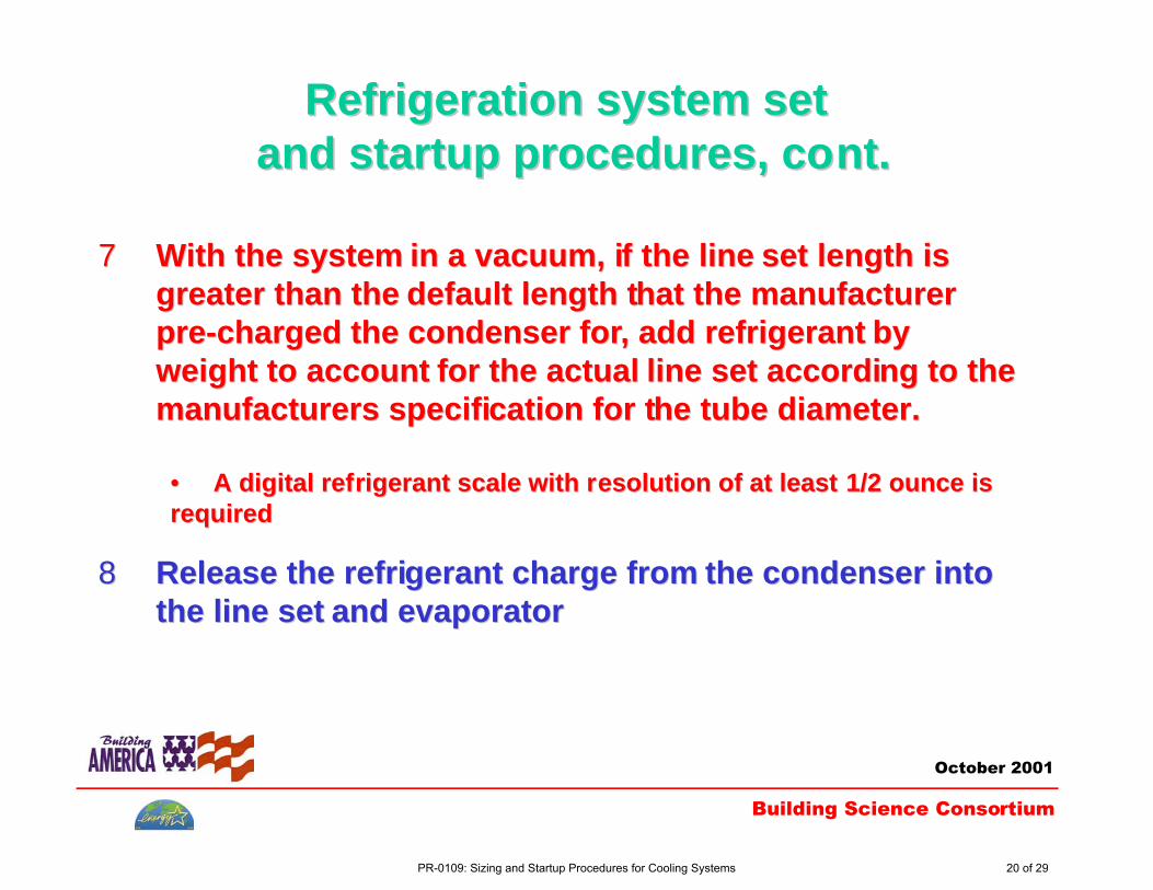
77 With the system in a vacuum, if the line set length isWith the system in a vacuum, if the line set length isgreater than the default length that the manufacturergreater than the default length that the manufacturerpre-charged the condenser for, add refrigerant bypre-charged the condenser for, add refrigerant byweight to account for the actual line set according to theweight to account for the actual line set according to themanufacturers specification for the tube diameter.manufacturers specification for the tube diameter.
•• A digital refrigerant scale with resolution of at least 1/2 ounce isA digital refrigerant scale with resolution of at least 1/2 ounce isrequiredrequired
88 Release the refrigerant charge from the condenser intoRelease the refrigerant charge from the condenser intothe line set and evaporatorthe line set and evaporator
PR-0109: Sizing and Startup Procedures for Cooling Systems 20 of 29

Refrigeration system setRefrigeration system set and startup procedures, cont. and startup procedures, cont.
Building Science Consortium
October 2001
99 If the line set length is less than the default length thatIf the line set length is less than the default length thatthe manufacturer pre-charged the condenser for, thenthe manufacturer pre-charged the condenser for, thenremove refrigerant to account for the actual line setremove refrigerant to account for the actual line setlength according to the manufacturers specification.length according to the manufacturers specification.
•• A digital refrigerant scale with resolution of at least 1/2 ounce isA digital refrigerant scale with resolution of at least 1/2 ounce isrequiredrequired
1010 Start the system and run for at least 15 minutesStart the system and run for at least 15 minutes
PR-0109: Sizing and Startup Procedures for Cooling Systems 21 of 29

Refrigeration system setRefrigeration system set and startup procedures, cont. and startup procedures, cont.
Building Science Consortium
October 2001
1111 Check for proper sub-cooling for TXV (thermalCheck for proper sub-cooling for TXV (thermalexpansion valve) systems.expansion valve) systems.
The required sub-cooling is specified by theThe required sub-cooling is specified by themanufacturer and is usually 5 - 15 F. It is not dependentmanufacturer and is usually 5 - 15 F. It is not dependenton inside or outside environmental conditions.on inside or outside environmental conditions.
Adjust refrigerant charge as necessary.Adjust refrigerant charge as necessary.
PR-0109: Sizing and Startup Procedures for Cooling Systems 22 of 29

Thermal expansion valve (TXV)Thermal expansion valve (TXV)refrigerant metering devicerefrigerant metering device
Building Science Consortium
October 2001
Txv.jpg
© buildingscience.com
PR-0109: Sizing and Startup Procedures for Cooling Systems 23 of 29

Refrigeration system setRefrigeration system set and startup procedures, cont. and startup procedures, cont.
Building Science Consortium
October 2001
1212 If indoor and outdoor environmental conditions areIf indoor and outdoor environmental conditions arefavorable, check for proper superheat for capillary tubefavorable, check for proper superheat for capillary tubeand accurator/piston systems. Superheat is dependentand accurator/piston systems. Superheat is dependenton inside and outside environmental conditions.on inside and outside environmental conditions.
If the target superheat is > 5 F, adjust refrigerant chargeIf the target superheat is > 5 F, adjust refrigerant chargeas necessary.as necessary.
PR-0109: Sizing and Startup Procedures for Cooling Systems 24 of 29

PR-0109: Sizing and Startup Procedures for Cooling Systems 25 of 29

Refrigeration system setRefrigeration system set and startup procedures, cont. and startup procedures, cont.
Building Science Consortium
October 2001
1313 Check for proper temperature drop across theCheck for proper temperature drop across the
evaporator coil (varies with return air dry bulb and wetevaporator coil (varies with return air dry bulb and wetbulb temperature, usually 15 - 25 F).bulb temperature, usually 15 - 25 F).
Check static pressures in the supply and returnCheck static pressures in the supply and returnplenums (max 125 Pa differential across blower).plenums (max 125 Pa differential across blower).
Correct for any airflow problems/restrictions asCorrect for any airflow problems/restrictions asnecessary.necessary.
PR-0109: Sizing and Startup Procedures for Cooling Systems 26 of 29

Refrigeration system setRefrigeration system set and startup procedures, cont. and startup procedures, cont.
Building Science Consortium
October 2001
According to the best engineering data available, the performance lossusing a TXV metering device is about 5% if the refrigerant charge is offby plus or minus 20%.
The performance loss using a fixed metering device (capillary tube oraccurator) is about 15% to 20% if the refrigerant charge is off by plus orminus 20%.
Therefore, TXV systems are best, however, by following the installationprocedure listed above, the refrigerant charge should be within about5% every time, limiting the performance loss to about 5%.
PR-0109: Sizing and Startup Procedures for Cooling Systems 27 of 29
Additional ResourcesAdditional Resources
Building Science Consortium
October 2001
• “Just the facts,” Thermal Engineering Company, Toledo, OH• “Fundamentals of dehydrating a refrigerant system,” Robinair
Manufacturing Corp., Montpelier, OH• “Influence of the expansion device on air-conditioner system
performance characteristics under a range of charging conditions,”Farzad and O’Neal, ASHRAE Transactions 1993, V. 99, Pt. 1.
• “Residential cooling load calculation methods analysis,” ProctorEngineering Group.
• “Soldering and brazing copper tube,” Copper DevelopmentAssociation Inc.
• “Three refrigerant states,” Wheeler, Contracting Business, Dec 1989.• “Split system space cooling refrigerant charge and air flow
measurement,” California Energy Commission, Contractor’s Report,#P 400-01-014, http://www.energy.ca.gov/reports.
PR-0109: Sizing and Startup Procedures for Cooling Systems 28 of 29