for contractors for condensing boilers installation ... · pdf fileinstallation instructions...
TRANSCRIPT

Installation instructionsfor contractors
VIESMANN
Flue system
for condensing boilers
Flue system
5780 223 GB 3/2017 Dispose after installation.

2
Please follow these safety instructions closely to prevent accidents andmaterial losses.
Safety instructions explained
DangerThis symbol warns against therisk of injury.
! Please noteThis symbol warns against therisk of material losses and envi-ronmental pollution.
NoteDetails identified by the word "Note"contain additional information.
Target group
These instructions are exclusivelyintended for qualified contractors.■ Work on gas installations may only
be carried out by a registered gas fit-ter.
■ Work on electrical equipment mayonly be carried out by a qualifiedelectrician.
Regulations to be observed
■ National installation regulations■ Statutory regulations for the preven-
tion of accidents■ Statutory regulations for environmen-
tal protection
■ Codes of practice of the relevanttrade associations
■ All current safety regulations asdefined by DIN, EN, DVGW, TRGI,TRF, VDE and all locally applicablestandardsa ÖNORM, EN,
ÖVGW G K directives,ÖVGW-TRF and ÖVE
c SEV, SUVA, SVGW, SVTI,SWKI, VKF and EKAS guideline1942: LPG, part 2
Safety instructions
5780
223
GB

3
Working on the system
■ Isolate the system from the powersupply (e.g. by removing the sepa-rate fuse or by means of a mains iso-lator) and check that it is no longer'live'.
■ Safeguard the system against recon-nection.
■ Where gas is used as the fuel, closethe main gas shut-off valve and safe-guard it against unintentional reopen-ing.
Safety instructions (cont.)
5780
223
GB

4
Installation sequenceGeneral installation information............................................................................ 5■ Design............................................................................................................... 5■ Flue gas temperature protection....................................................................... 5■ Installation information...................................................................................... 5■ Required tools/equipment................................................................................. 6■ Fitting the balanced flue slide coupling............................................................. 7■ Tightness test.................................................................................................... 8■ Certification of the balanced flue system.......................................................... 8■ System certification........................................................................................... 8Installations requirements.................................................................................... 9■ Statutory requirements...................................................................................... 9■ Gas safety (installation and use) regulations (current issue)............................ 9■ Boiler position................................................................................................... 10Routing through a shaft........................................................................................ 15■ Installation information...................................................................................... 15■ Rigid flue........................................................................................................... 16■ Flexible flue....................................................................................................... 26Vertical outlet for pitched or flat roofs................................................................... 36■ Maximum flue length......................................................................................... 36■ Installation......................................................................................................... 38External wall connection....................................................................................... 41■ Installation......................................................................................................... 43Routing over an external wall............................................................................... 45■ Maximum flue length......................................................................................... 46■ Installation......................................................................................................... 46Plume kit............................................................................................................... 48■ Routing options................................................................................................. 48
Index
5780
223
GB

5
Design
Prior to installation, check that the max-imum possible pipe length will not beexceeded.Max. possible pipe lengths in relation tothe boiler used:
Flue systems technical guide
Flue gas temperature protection
The flue pipes are approved for fluegas temperatures up to 120 °C.
With Viessmann condensing boilers,internal safeguards ensure that themaximum permissible flue gas temper-ature is not exceeded.
Installation information
■ The component overviews for the dif-ferent types of routing also apply tofloorstanding condensing boilers.
■ Keep flue gas routes short and withthe fewest number of bends possible.
■ Route horizontal connection pipeswith a fall of ≥ 3° (approx. 50 mm/m)towards the boiler.
■ Support horizontal connection pipesat intervals of approx. 1 m.
■ To avoid damage and leaks, isolatethe flue system from sources of vibra-tion (e.g. ventilation systems).
■ Check whether the gaskets in allfemale connections are correctlyseated.
■ Prior to installation, lubricate all gas-kets with the lubricating paste provi-ded.
■ Use only the special gaskets suppliedwith the boiler.
■ Female plug-in connections in theflue gas path must always point in thedirection of flow.
■ Use only the components suppliedwith the Viessmann flue system.
■ Push the pipes into each other with aslight twisting motion.
■ Balanced flue pipes can be trimmedin their assembled state.
Only carry out commissioning whenthe following conditions have been met:■ Unrestricted flow in the flue gas
routes.■ Positive pressure flue system is gas-
tight.■ Inspection port covers checked for
secure and tight seating.■ Apertures for supplying sufficient
combustion air are open and cannotbe closed.
■ All current regulations on installingand commissioning flue systemshave been observed.
General installation information57
80 2
23 G
B

6
DangerLeaking or blocked flue sys-tems, or an inadequate supplyof combustion air can cause lifethreatening poisoning from car-bon monoxide in the flue gas.
Ensure the flue system is ingood working order. Vents forsupplying combustion air mustbe non-closable.
Required tools/equipment
■ Rope for lowering the flue systeminto a shaft (length: Chimney heightplus 3 m)
■ Saw and file for trimming and cham-fering the pipe sections
■ Power drill for securing the shaftcover and support rail
General installation information (cont.)
5780
223
GB

7
Fitting the balanced flue slide coupling
NoteThe slide coupling can compensate fora gap of approx. 45 mm. Prior to instal-lation, compensate for surplus or insuf-ficient length on the incoming pipe.
1.
120
4.
3.
5.
6.
2.
1. Push the pipe section into thefemale connection of the incomingbalanced flue component.
2. Shorten the ongoing balanced fluepipe to create a gap of 120 mmbetween the pipe section and thebalanced flue pipe.
3. Push the slide coupling onto theongoing flue pipe.
4. Open the collar and push it over theongoing balanced flue pipe.
5. Pull the slide coupling out and pushit onto the incoming flue pipe.
6. Align the collar and close the togglefasteners.
General installation information (cont.)
5780
223
GB

8
Tightness test
After installation, flue systems routedthrough a shaft must be tested for tight-ness by the flue gas inspector [checklocal regulations].■ Pressurised flues which are routed
inside buildings and which are notsurrounded by combustion air (openflue) must be pressure-tested.For the pressure test, a leak detectoris used to pump air into the flue,which has been sealed at the top andbottom, until a pressure of 200 Pahas built up. This pressure is main-tained while the volume of air leakingout is established.A leakage rate of up to0.006 l/(s x m2), relative to the inter-nal surface area, is permitted forclassifying a flue as sufficiently gas-tight.
■ In pressurised flues that are surroun-ded by combustion air (room sealed),the tightness can be checked by test-ing the O2 content in the combustionair (annular gap test).The flue is considered sufficientlygas-tight if the O2 content in the com-bustion air does not deviate from thereference value by more than the fol-lowing values. The reference value isestablished following the self-adjust-ment of the test meter:– For flues with general building reg-
ulations approval 0.4 % by vol.– For other flues 0.2 % by vol.
NoteObserve country-specific regulations.
Certification of the balanced flue system
The balanced flue system is CE desig-nated and approved in accordance withEN 14471. See the flue systems techni-cal guide and enclosed "System certifi-cation" labels.
System certification
System certification to EC Gas Applian-ces Directive EU/2009/142/EC in con-junction with PPs flues offered by Sko-berne.
NoteAffix the "System certification" and"Flue system ..." labels clearly visiblenear the flue system or on the boiler.
The labels are supplied with the techni-cal documentation.
General installation information (cont.)
5780
223
GB

9
Statutory requirements
The appliance is suitable only for instal-lation in GB and IE and should beinstalled in accordance with the rules inforce. In GB a Gas Safe RegisteredInstaller must carry out the installation.It must be carried out in accordancewith the relevant requirements of the:
Gas safety (installation and use) regulations (current issue)
It is in your own interest and safety toensure that the law is complied with.In addition to the above regulations,this appliance must be installed inaccordance with the current IEE WiringRegulations for electrical installation(BS 7671), local Building Regulations,the Building Standards (Scotland)(Consolidation) Regulations, bye lawsof the local water undertaking andHealth and Safety Document NO. 635,The Electricity at Work regulations1989, In Ireland (IE), the installationmust be carried out by a CompetentPerson and installed in accordance withthe current edition if I.S.813 "DomesticGas Installations", The current BuildingRegulations and references should bemade to the current ETCI rules for elec-trical installation.It should also be in accordance with therelevant recommendations in the cur-rent editions of the following BritishStandards and Codes of Practice: BS5449, BS 5546, BS 5440:1, BS 5440:2,BS 6798, BS 7593, BS 6891, IGE/UP/7and IS 813 for IE.
All Registered installers are required tonotify building control when they haveinstalled or exchanged a gas appliancein a residential dwelling, this can bedone via Gas Safe.Gas Safe will then issue either a Build-ing Compliance Certificate (for Englandand Wales) or a Declaration of Safety(Scotland, Northern Island, Isle of Manor appliances out of the scope of Build-ing Regulations) to the homeowner,which will confirm that the work hasbeen carried out by a competent GasSafe Registered Installer. This docu-ment will be used to form part of theHome Information Pack (HIP).
! Please noteManufacturers instructions mustnot be taken in any way as overriding statu-tory obligations.
Installations requirements57
80 2
23 G
B

10
Boiler position
The following limitations must beobserved when siting the boiler:■ The boiler is not suitable for external
installation. The position selected forthe installation should be within thebuilding, unless otherwise protectedby a suitable enclosure and mustallow adequate space for installation,servicing and operation of the appli-ance and for air circulation around it.
■ The position must allow for a suitableflue system and terminal position.The boiler must be installed on a flatvertical wall capable of supporting theweight of the appliance and anyancillary equipment when full.
■ Due consideration should be given tothe routing of the condensate drainfrom the chosen position.
■ If the boiler is to be fitted in a timberframed building it should be fitted inaccordance with ige/up/7. If in doubtadvice must be sought from the Insti-tute of Gas Engineers.
■ If the appliance is to be installed in aroom containing a bath or shower,any electrical switch or control utilis-ing mains electricity must be so situ-ated that it cannot be touched by aperson using the bath or shower.Attention is drawn to the require-ments of BS 7671 (the current I.E.EWiring Regulations) and in Scotlandthe electrical provisions of the Build-ing Regulations applicable in Scot-land.
■ A compartment used to enclose theappliance must be designed and con-structed specifically for this purpose.An existing cupboard or compartmentmay be used provided it is modifiedaccordingly. BS 7698:2000 givesdetails of the essential features ofcupboard / compartment design,including airing cupboards. TheVitodens range does not requirecompartment ventilation.
■ Where installation will be in anunusual location, special proceduresmay be necessary. BS 6798 givesdetailed guidance on this aspect.
Installations requirements (cont.)
5780
223
GB

11
Flue terminal position
Horizontal flue system
a
g
f
h,i
d,n
j
b,c
k m
e
g
af
f
k
b,c
k
l l
g
c
k
Position Minimum spacingmm
a Directly below an opening window, air vent orany other ventilation opening
300
b Below a gutter drain or soil pipe 75c Below eaves 200d Below a balcony 200e From vertical drain or soil pipes 150f From internal and external corners 300g Above adjacent ground or balcony level/roof 300h From a surface facing the terminal 600i Facing terminals 1200j From opening door/window 1200k Vertically from a terminal on same wall 1500l Horizontally from a terminal on same wall 300m Adjacent to opening 300n Below carport/roof not recommended
Installations requirements (cont.)
5780
223
GB

12
Vertical flue systemsq
oo
r
p
s
t
u
t
Position Minimum spacingmm
o From adjacent wall 300p From adjacent opening window 1000q From another terminal 600r Minimum height 300s Minimum distance measured perpendicular to
roof covering400
t Beside or above an opening rooflight 600u Below an opening rooflight 2000
Installations requirements (cont.)
5780
223
GB

13
Minimum distance from terminal
2.5 mA
A Boundary
Not under a car port
Installations requirements (cont.)
5780
223
GB

14
2.1
m
B
Avoid access routes and patios
B Walkway or patio
2.5 m
C
Minimum distance to car parking space
C Car space
Installations requirements (cont.)
5780
223
GB

15
Installation information
Prior to installation, the local flue gasinspector should check that the shaft tobe used is suitable and permissible[where applicable].Ventilation air ducts with which oil orsolid fuel boilers were previously usedmust not contain any sulphur or sootdeposits on the inner surfaces of thechimney. Sulphur and soot depositscause faults. If thorough cleaning is notpossible, a balanced flue pipe must belaid through the shaft. Alternatively, aseparate balanced flue can be routed.In the installation room, at least oneinspection port must be provided in theflue system for inspection, cleaning andpressure testing (if required). If the flueis not accessible from the roof, a sec-ond inspection port must be providedbehind the chimney cleaning hatch inthe attic.
Provide an inspection port at the baseof the shaft for inspecting the secon-dary ventilation. Safeguard condensatedrainage from the flue to the boiler witha fall of at least 3° (approx. 50 mm/m).The flue system must protrude abovethe roof line. Observe 400 mm protru-sion from the roof parallel to the roofslope according to FeuVo [or local reg-ulations].
Routing through a shaft57
80 2
23 G
B

16
Rigid flue
Room sealed operation
B5
2
A
3
23
2
4
3
2
2
6798 71
A
C
B
C
A Ventilation airB Flue gasC Inspection port
1 Boiler flue connection2 Standard shaft pack Comprising: ■ Support bend ■ Support rail ■ Shaft cover ■ Spacers (5 pce)3 Flue pipe 2 m long 1 m long 0.5 m long Flue bend (for use in corbelled
chimneys) 30° or 15° 4 Inspection piece, straight5 Balanced flue inspection piece,
straight6 Balanced flue wall bezel7 Balanced flue pipe 1 m long 0.5 m long8 Balanced flue bend 87° or 2 x 45° or Balanced flue inspection tee or Balanced flue inspection bend9 Balanced flue slide coupling Fixing clamp Balanced flue adaptor
7 60/100 mm to 7 80/125 mm
Maximum flue length
Vitodens 100-W, type WB1B: 10 m
Routing through a shaft (cont.)
5780
223
GB

17
Vitodens 100-W, types B1HA and B1KA, Vitodens 111-WRated heating output kW 26.0 26.0 30.0 35.0System size 60/100 m 15 15 15 15System size 80/125 m 25 20 20 20
Vitodens 200-W, 222-F and 242-FRated heatingoutput
kW 13 19 26 35 45 60 80 100
System size60/100
m 20 20 20 15 — — — —
System size80/125
m 25 25 25 25 20 15 — —
System size110/150
m — — — — 25 20 20 20
NoteFor alternative system sizes, a bal-anced flue adaptor is required.
The following components are takeninto consideration for the maximum fluelengths:■ Balanced flue connection pipe 0.5 m
long■ 1 balanced flue bend 87° and 1 sup-
port bend 87°or
■ 2 balanced flue bends 45° and 1 sup-port bend 87°
If fitting other bends, tees or straightlengths, subtract the following valuesfrom the maximum length:■ Balanced flue connection pipe 0.5 m
long: 1 m■ Balanced flue connection pipe 1 m
long: 2 m■ Balanced flue bends 45°: 0.5 m■ Balanced flue bends 87°: 1 m■ Balanced flue inspection tee: 1.5 m
Routing through a shaft (cont.)
5780
223
GB

18
Open flue operation
3
23
4
3
2
2
2
2
1 65 4
A
B
A
D
E
C
3
A Secondary ventilationB Flue gasC Inspection portD Ventilation air apertureE Ventilation air
1 Boiler flue connection2 Standard shaft pack Comprising: ■ Support bend ■ Support rail ■ Shaft cover ■ Spacers (5 pce)3 Flue pipe 2 m long 1 m long 0.5 m long Flue bend (for use in corbelled
chimneys) 30° or 15°4 Inspection piece, straight5 Flue bend 87° or 2 x 45° or Inspection tee 87°6 Vent bezel Adaptor 7 60 mm to 7 80 mm
Routing through a shaft (cont.)
5780
223
GB

19
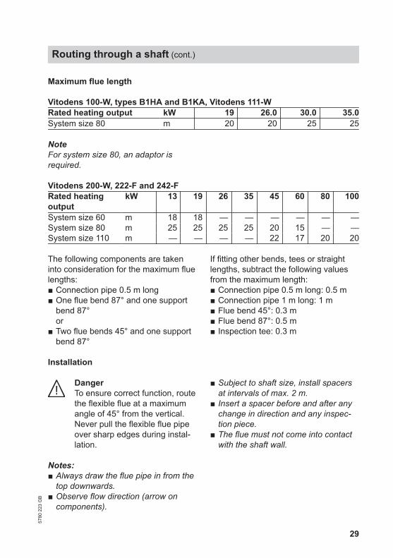
Maximum flue length
Vitodens 100-W, types B1HA and B1KA, Vitodens 111-WRated heating output kW 19 26.0 30.0 35.0System size 60 m 15 15 20 20System size 80 m 20 20 20 20
NoteFor system size 80, an adaptor isrequired.
Vitodens 200-W, 222-F and 242-FRated heatingoutput
kW 13 19 26 35 45 60 80 100
System size 60 m 20 20 20 15 — — — —System size 80 m 25 25 25 25 20 15 — —System size 110 m — — — — 25 20 20 20
The following components are takeninto consideration for the maximum fluelengths:■ Connection pipe 0.5 m long■ One flue bend 87° and one support
bend 87°or
■ Two flue bends 45° and one supportbend 87°
If fitting other bends, tees or straightlengths, subtract the following valuesfrom the maximum length:■ Connection pipe 0.5 m long: 0.5 m■ Connection pipe 1 m long: 1 m■ Flue bend 45°: 0.3 m■ Flue bend 87°: 0.5 m■ Inspection tee: 0.3 m
Open flue operation with combustion air supply via interconnected rooms
Only possible with system sizes 60 and80.The connection piece to the shaft isconstructed as part of the balanced fluesystem. The combustion air is drawnfrom the room via an opening immedi-ately by the chimney entry (air inletadaptor).An adequate combustion air supply, asspecified by the TRGI 2008, must beensured inside the room by means ofan interconnected combustion air sup-ply:
■ Minimum volume of the interconnec-ted rooms, 4 m3 per kW rated heatingoutput
■ Vents in the connecting doorsmin. 150 cm2
Routing through a shaft (cont.)
5780
223
GB

20
3
3
2
4
3
2
2
578
6
C
1
CB
A
E
D
A Ventilation airB Flue gasC Secondary ventilationD Aperture for interconnected air
supplyE Inspection port
1 Boiler flue connection2 Standard shaft pack Comprising: ■ Support bend ■ Support rail ■ Shaft cover ■ Spacers (5 pce)3 Flue pipe 2 m long 1 m long 0.5 m long Flue bend (for use in corbelled
chimneys) 30° or 15°4 Inspection piece, straight5 Balanced flue inspection piece,
straight6 Balanced flue air inlet adaptor7 Balanced flue pipe 1 m long 0.5 m long8 Balanced flue bend 87° or 2 x 45° or Balanced flue inspection tee or Balanced flue inspection bend
Routing through a shaft (cont.)
5780
223
GB

21
Installation
Ø 1
2
D
C
B
A
01. Drill a 7 12 mm hole through thecentre of the rear shaft wall tosecure support rail A.
02. Insert support rail A into the dril-led hole and secure to the frontshaft wall with screws or mortar.
03. Position support bend B and usethe pin to secure it in a hole in thesupport rail.
04. Attach installation rope C to theoutside of the lowest vertical pipesection.
05. Subject to shaft size, install aspacer D every 2 to 5 m and foreach profiled piece (e.g. inspectionpiece or bend). Bent ends facingup.
06. Apply lubricating paste and pushthe pipes into each other with aslight twisting motion.
07. Lower the pipes into the shaftusing installation rope C.
08. Remove the rope and push thelowest pipe into support bend B.
Routing through a shaft (cont.)
5780
223
GB

22
345
50+0 -2
0
G
K
H
F
E
System size 60 to 110 mm
09. Have highest pipe section E end-ing approx. 50 mm below the topedge of the shaft.
10. Secure the lower part of shaftcover F.
50+0 -2
0
≈ 36
0
G
HK
F
E
System size 125 to 200 mm
11. System size 60 to 110 mm:Push on terminal pipe G.
NoteTo maintain the required weight,never trim terminal pipe G.
System size 125 to 200 mm:Trim final pipe section G (withoutfemale connection). The pipeshould be as flush as possible withfitted flue collar H.
50+0 -2
0
500
E
K
G
F
H
System size 250 mm
12. Push on flue collar H and fastensafety rope K to the lower part.
Routing through a shaft (cont.)
5780
223
GB

23
Fitting the connection pipe
M
L
1. Only for room sealed operation:Trim final ventilation air pipe L ofthe connection pipe so that it endslevel with the internal shaft wall sur-face.
N
O
2. Room sealed operation:Slide balanced flue wall bezel Monto the pipe and push it againstthe shaft opening.Open flue operation:Slide vent bezel N onto the pipeand push it against the shaft open-ing.
NoteThe gap created provides secon-dary ventilation to the shaft.No additional ventilation grille isrequired.
Open flue operation with combus-tion air supply via interconnectedrooms:Push the flue pipe onto the supportbend. Slide on air inlet adaptor Oand secure it to the shaft.
Fitting a metal shaft cover
For routing a plastic flue inside a twinflue shaft, in conjunction with a solidfuel boiler.The metal end piece must protrude intothe shaft by a length that is equal to orgreater than the flue pipe diameter.
If necessary, use the stainless steelextension, which is available as anaccessory.
Routing through a shaft (cont.)
5780
223
GB

24
200
80±1
050 1. Have the highest pipe section end
approx. 80 mm below the top edgeof the shaft.
B
A
2. Push on metal pipe section A. Ifrequired, use an extension (acces-sories).
3. Position shaft cover B and secureto the shaft with the fixing materialsprovided.
Routing through a shaft (cont.)
5780
223
GB

25
Stainless steel extension in conjunction with on-site shaft cover
≥ 2
x D
CA
B
Ø D
≥400
A Chimney extension made fromsoot fire resistant material
B Stainless steel extensionC Shaft cover (on-site)
The shaft cover as a common down-draught plate (chimney cowl) must beprovided on site.
Routing through a shaft (cont.)
5780
223
GB

26
Flexible flue
Room sealed operation
68qP91 72A
2
5
2
4
2
3
2
2
B
A
C
C
A Ventilation airB Flue gasC Inspection port
1 Boiler flue connection2 Standard shaft pack (flexible) Comprising: ■ Support bend ■ Connection pieces ■ Support rail ■ Shaft cover ■ Spacers (5 pce)3 Inspection piece, straight (for installation in the flexible flue)4 Flexible flue5 Connection piece for connecting residual lengths of
the flexible flue Pipe lowering attachment with 20 m rope6 Balanced flue inspection piece,
straight7 Wall bezel8 Balanced flue pipe 1 m long 0.5 m long9 Balanced flue bend 87° or 2 x 45° or Balanced flue inspection tee or Balanced flue inspection bendqP Balanced flue slide coupling Balanced flue adaptor
7 60/100 mm to 7 80/125 mm
Routing through a shaft (cont.)
5780
223
GB

27
Maximum flue length
Vitodens 100-W, types B1HA and B1KA, Vitodens 111-WRated heating output kW 19 26.0 30.0 35.0System size 80 m 20 20 20 20
NoteFor system size 80, an adaptor isrequired.
Vitodens 200-W, 222-F and 242-FRated heatingoutput
kW 13 19 26 35 45 60 80 100
System size 60 m 18 18 — — — — — —System size 80 m 25 25 25 25 20 15 — —System size 110 m — — — — 22 17 20 20
The following components are takeninto consideration for the maximum fluelengths:■ Balanced flue connection pipe 0.5 m
long■ One flue bend 87° and one support
bend 87°or
■ Two flue bends 45° and one supportbend 87°
If fitting other bends, tees or straightlengths, subtract the following valuesfrom the maximum length:■ Connection pipe 0.5 m long: 0.5 m■ Connection pipe 1 m long: 1 m■ Flue bend 45°: 0.3 m■ Flue bend 87°: 0.5 m■ Inspection tee: 0.3 m
Routing through a shaft (cont.)
5780
223
GB

28
Open flue operation
2
2
1 976 A
D
E
C
2
2
5
2
4
2
3
B
A
8
A Secondary ventilationB Flue gasC Inspection portD Ventilation air apertureE Ventilation air
1 Boiler flue connection2 Standard shaft pack (flexible) Comprising: ■ Support bend ■ Connection pieces ■ Support rail ■ Shaft cover ■ Spacers (5 pce)3 Inspection piece, straight (for installation in the flexible flue)4 Flexible flue5 Connection piece for connecting residual lengths of
the flexible flue Pipe lowering attachment with 20 m rope6 Inspection piece, straight7 Flue pipe 1 m long 0.5 m long8 Flue bend 87° or 2 x 45° or Inspection tee 87°9 Vent bezel Adaptor 7 60 mm to 7 80 mm
Routing through a shaft (cont.)
5780
223
GB
29
Maximum flue length
Vitodens 100-W, types B1HA and B1KA, Vitodens 111-WRated heating output kW 19 26.0 30.0 35.0System size 80 m 20 20 25 25
NoteFor system size 80, an adaptor isrequired.
Vitodens 200-W, 222-F and 242-FRated heatingoutput
kW 13 19 26 35 45 60 80 100
System size 60 m 18 18 — — — — — —System size 80 m 25 25 25 25 20 15 — —System size 110 m — — — — 22 17 20 20
The following components are takeninto consideration for the maximum fluelengths:■ Connection pipe 0.5 m long■ One flue bend 87° and one support
bend 87°or
■ Two flue bends 45° and one supportbend 87°
If fitting other bends, tees or straightlengths, subtract the following valuesfrom the maximum length:■ Connection pipe 0.5 m long: 0.5 m■ Connection pipe 1 m long: 1 m■ Flue bend 45°: 0.3 m■ Flue bend 87°: 0.5 m■ Inspection tee: 0.3 m
Installation
DangerTo ensure correct function, routethe flexible flue at a maximumangle of 45° from the vertical.Never pull the flexible flue pipeover sharp edges during instal-lation.
Notes:■ Always draw the flue pipe in from the
top downwards.■ Observe flow direction (arrow on
components).
■ Subject to shaft size, install spacersat intervals of max. 2 m.
■ Insert a spacer before and after anychange in direction and any inspec-tion piece.
■ The flue must not come into contactwith the shaft wall.
Routing through a shaft (cont.)
5780
223
GB

30
Fitting the support rail inside the shaft
Ø 1
2
A
1. Drill a 7 12 mm hole through thecentre of the rear shaft wall tosecure support rail A.
2. Insert support rail A into the drilledhole and secure to the front shaftwall with screws or mortar.
Fitting an inspection piece, connection piece or connector
123
1
A
B
C
D
Routing through a shaft (cont.)
5780
223
GB

31
1. Trim flexible flue pipe A cleanly ata right angle.
2. Click spacer tooth of mountingring B into the 3rd groove of flexi-ble flue A.
3. Insert gasket C into the 1st grooveof flexible flue A.
4. Push inspection piece, connectionpiece or connector D onto mount-ing ring B until it clicks into posi-tion.
Fitting pipe lowering attachment and drawing flexible flue into shaft
A
B
C
01. Compress the end of flexibleflue A into a slightly oval shape.Insert plate B of the pipe loweringattachment into the 3rd groove ofthe flue pipe.
02. Push leading cone C onto flexibleflue A. The end of the flue pipemust be fully covered.
03. Secure the rope to the loop of thepipe lowering attachment.
Routing through a shaft (cont.)
5780
223
GB

32
E
DE
A
04. Push spacer D onto flue A (bentends in flue gas flow direction).
05. Place provided cable ties Earound the ring of spacers D andtighten.
06. Pull flexible flue A into the shaftfrom the top downwards. Neverpull the flue over sharp edges.
07. Remove the pipe lowering attach-ment from the flue.
G
F
08. Fit connector F to flue A (seepage 30).
09. Position support bend G andsecure it in a hole in the supportrail with the pin.
10. Coat connector F with lubricatingpaste and push into support bendG.
Routing through a shaft (cont.)
5780
223
GB

33
Fitting a plastic shaft cover
200
H
G
F
E
D
C
B
A
1. Route flexible flue A through shaftcover B.
2. Trim flexible flue A 200 mm abovethe top edge of the shaft.
3. Position the base of shaft cover Bon the shaft and secure.
4. Only for 7 60 and 80 mm:Position reducer ring C on thebase of shaft cover B.
5. Click the spacer tooth of mountingring D into the 3rd groove of flexi-ble flue A. See page 30.
6. Insert gasket E into the 1st grooveof flexible flue A.
7. Push terminal pipe F onto mount-ing ring D until it clicks into posi-tion.
8. Hook safety rope G into the drilledhole in shaft cover B.
9. Push cowl H over terminal pipeF and click into place on shaftcover B.
Routing through a shaft (cont.)
5780
223
GB

34
Fitting a metal shaft cover
~50
G
E
F
D
C
B
A
1. Route flexible flue A throughretainer B.
2. Position retainer B on the shaft.
3. Trim flue A approx. 50 mm abovethe retaining plate of retainer B.
4. Pull flexible flue A up far enoughto allow mounting ring C to be fit-ted.Click mounting ring C into the 3rdgroove of flexible flue A. Seepage 30.
5. Insert gasket D into the 1st grooveof flexible flue A.
6. Push adaptor E onto mountingring C until it clicks into position.
7. Push terminal pipe F into adaptorE.
8. Push cowl G onto terminal pipeF and secure.
Routing through a shaft (cont.)
5780
223
GB

35
Fitting the connection pipe
B
A
1. Only for room sealed operation:Trim final ventilation air pipe A ofthe connection pipe so that it endslevel with the internal shaft wall sur-face.
D
C 2. Room sealed operation:Slide balanced flue wall bezel Bonto the pipe and push it againstthe shaft opening.Open flue operation:Slide vent bezel C onto the pipeand push it against the shaft open-ing.
NoteThe gap created provides secon-dary ventilation to the shaft.No additional ventilation grille isrequired.
Open flue operation with combus-tion air supply via interconnectedrooms:Push the flue pipe onto the supportbend, slide air inlet adaptor D ontothe pipe and secure it to the shaft.
Routing through a shaft (cont.)
5780
223
GB

36
If the balanced flue system is routedthrough roof spaces that are not usedas accommodation, run the flue throughan additional metal pipe as protectionagainst mechanical damage(TRGI 2008).
If several roof outlets are installed sideby side: Observe a minimum clearanceof 1.5 m between outlets and to otherbuilding structures (e.g. skylights) inaccordance with TRGI 2008. Observethe clearance of the flue outlet abovethe roof (see diagram). If the ratedheating output is ≥ 50 kW, an above-roof extension is required (seepage 40).
a
1
3
4
5
7
B
A
2
6
A Ventilation airB Flue gas
Rated heating out-put
kW ≤50 ≥50
a (min.) mm 400 1000
1 Boiler flue connection2 Balanced flue roof outlet3 Pipe outlets for Klöber roof
tilesProvide a suitable Klöber roof tileon site.orUniversal roof tile or Flat roof collar
4 Balanced flue inspection piece,straight
5 Balanced flue slide coupling6 Balanced flue bend 87° or 2 x 45° Balanced flue pipe 1 m long 0.5 m long7 Fixing clamp Balanced flue adaptor
7 60/100 mm to 7 80/125 mm
Maximum flue length
Vitodens 100-W, type WB1B: 10 m
Vertical outlet for pitched or flat roofs
5780
223
GB

37
Vitodens 100-W, types B1HA and B1KA, Vitodens 111-WRated heating output kW 19 26.0 30.0 35.0System size 60/100 m 10 10 8 8System size 80/125 m 13 13 11 11
Vitodens 200-W, 222-F and 242-FRated heatingoutput
kW 13 19 26 35 45 60 80 100
System size60/100
m 10 10 10 10 — — — —
System size80/125
m 13 13 13 11 10 6 — —
System size110/150
m — — — — 13 9 15 15
NoteFor alternative system sizes, a bal-anced flue adaptor is required.
The following components are takeninto consideration for the maximum fluelengths:■ 2 balanced flue bends 87°
If fitting other bends, tees or straightlengths, subtract the following valuesfrom the maximum length:■ Balanced flue bend 45°: 0.5 m■ Balanced flue bend 87°: 1 m■ Balanced flue inspection tee: 0.5 m
Vertical outlet for pitched or flat roofs (cont.)
5780
223
GB

38
Installation
Balanced flue roof outlet
2
7
6
3
! Please noteEnsure the specified minimumlengths above the roof areobserved.Never trim roof outlets abovethe roof.
■ Install pipe outlets for Klöber rooftiles, universal roof tiles or flat roofcollars in accordance with manufac-turer's instructions.
■ Integrate the flat roof collar into theroof skin according to the flat roofguidelines.
■ Ceiling/roof penetration (min. diame-ter):– 105 mm (system size 60)– 130 mm (system size 80)– 160 mm (system size 110).
■ Secure the roof outlet to the roofstructure with a clamp only afterinstallation has been completed.
■ Position the roof outlet on the rooftiles or flat roof collar from above.
■ Connect the balanced flue connec-tion pipe from below.
Vertical outlet for pitched or flat roofs (cont.)
5780
223
GB

39
Roof construction in line with the flatroof directive
CDE
FD
G
B
H
A
A Flat roof collarB Gravel ballast layer
C Insulation layerD Ventilation layerE Thermal insulationF InsulationG CeilingH Flue pipe
Vertical outlet for pitched or flat roofs (cont.)
5780
223
GB

40
Fitting an above-roof extension
System sizes 60 and 80
3x
3x
B
A
C
D
C
B
C
B
1. Push the internal pipe of above-roofextension A onto roof outlet Band secure with 3 screws provided.
2. Push black pipe section C ontoroof outlet B and secure with 3screws provided.
3. Push roof outlet B with above-roofextension A onto the balancedflue pipe.
4. Secure the 1 m above-roof exten-sion with clamp D provided andthe ropes.
Vertical outlet for pitched or flat roofs (cont.)
5780
223
GB

41
System size 110
A
B
1. Remove top section A of the roofoutlet.
2. Push above-roof extension B ontothe roof outlet.
3. Push top section A onto above-roof extension B.
NoteFor extensions ≥ 1 m, secure theroof outlet with ropes. The ropescan be fastened to the above-roofextension.
External wall connection
NoteCannot be used with the Vitocrossal orVitoladens.
Install an inspection port in the bal-anced flue pipe for inspection andcleaning.
Recommendation: To facilitate installa-tion of the balanced flue pipe, use thebalanced flue slide coupling.Route the connection piece with a fallof at least 3° (approx. 50 mm/m).
Vertical outlet for pitched or flat roofs (cont.)
5780
223
GB

42
651 7 4 42
B
A3
A Ventilation air B Flue gas
1 Boiler flue connection2 Balanced flue external wall
connection (incl. wall bezels)3 Grille4 Balanced flue pipe 1 m long 0.5 m long5 Balanced flue bend 87° or 2 x 45° or Balanced flue inspection tee or Balanced flue inspection bend6 Balanced flue inspection piece,
straight7 Balanced flue slide coupling Fixing clamp Balanced flue adaptor
7 60/100 mm to 7 80/125 mm
Maximum flue length
Vitodens 100-W, type WB1B: 10 m
External wall connection (cont.)
5780
223
GB

43
Vitodens 100-W, types B1HA and B1KA, Vitodens 111-WRated heating output kW 19 26.0 30.0 35.0System size 60/100 m 10 10 8 8System size 80/125 m 13 13 11 11
Vitodens 200-W, 222-F and 242-FRated heatingoutput
kW 13 19 26 35 45 60 80 100
System size 60 m 10 10 10 8 — — — —System size 80 m 13 13 13 11 10 6 — —System size 110 m — — — — 13 9 15 15
NoteFor alternative system sizes, a bal-anced flue adaptor is required.
The following components are takeninto consideration for the maximum fluelengths:■ 2 balanced flue bends 87°
If fitting other bends, tees or straightlengths, subtract the following valuesfrom the maximum length:■ Balanced flue bend 45°: 0.5 m■ Balanced flue bend 87°: 1 m■ Balanced flue inspection tee: 0.5 m
Installation
C B A
a bc
Balanced flue system 7 60/100 mm and 7 80/125 mm
External wall connection (cont.)
5780
223
GB

44
Balanced flue sys-tem (7 mm)
60/100 80/125
a (mm) ≤ 475 ≤ 710b (mm) 155 165c (mm) 704 952
Telescopic balanced flue externalwall connectionBalanced flue sys-tem (7 mm)
60/100
a (mm) ≥373 - ≤ 533b (mm) 154c (mm) ≥617 - ≤ 777
C B A
730
475 160
Balanced flue system 7 110/150 mm
1. Create an opening in the wall (min.diameter):■ 105 mm (system size 60)■ 130 mm (system size 80)■ 160 mm (system size 110)
2. Push external wall connection Awith wall bezel B into the wallopening.
3. Slide on internal wall bezel C.
4. If the external wall connection ter-minates ≤ 2 m above ground levelnear public roads, fit a protectivegrille (on-site fixing materials).
5. Connect the balanced flue connec-tion pipe from the inside and routewith a fall of min. 3° (approx.50 mm/m) towards the boiler.
External wall connection (cont.)
5780
223
GB

45
21
6
7
8
9
qP
5
B
5
3
qW
43
A 2
m:
qR
A
7
C
qE
qR
qP
A Flue gasB Ventilation airC Elbow in the external wall routing
for a short roof overhang
1 Boiler flue connection2 Balanced flue inspection tee,
87°
orBalanced flue inspection bend,87°
3 Balanced flue slide coupling4 Balanced flue pipe 1.95 m long 1 m long 0.5 m long5 Wall bezel6 Fixing clamp7 Balanced flue inspection piece,
straight External wall pack with8 Balanced flue bend, 87° or ex-
ternal wall bend, 87° 9 External wall air inlet sectionqP Balanced flue pipe or external
wall pipe 1.95 m long 1 m long 0.5 m longqQ Balanced flue roof outlet (for a large roof overhang)qW Universal roof tile or Pipe outlet for Klöber roof tiles Provide a suitable Klöber roof tile
on site.qE External wall terminal
(for short protrusion above theroof)
qR Balanced flue bend, 45° or ex-ternal wall bend, 45° orBalanced flue bend, 30° or ex-ternal wall bend, 30°
Balanced flue adaptor7 60/100 mm to 7 80/125 mm
Routing over an external wall57
80 2
23 G
B

46
Maximum flue length
Vitodens 100-WRated heating output kW 19.0 26.0 30.0 35.0System size 60/100 m 20 20 15 15System size 80/125 m 25 25 20 20
Vitodens 200-W, 222-F and 242-FRated heatingoutput
kW 13 19 26 35 45 60 80 100
System size60/100
m 20 20 20 15 — — — —
System size80/125
m 25 25 25 20 12 12 — —
System size110/150
m — — — — 17 17 20 20
NoteFor alternative system sizes, a bal-anced flue adaptor is required.
The following components are takeninto consideration for the maximum fluelengths:■ 2 balanced flue bends 87°
If fitting other bends, tees or straightlengths, subtract the following valuesfrom the maximum length:■ Balanced flue bend 45°: 0.5 m■ Balanced flue bend 87°: 1 m■ Balanced flue inspection tee: 0.5 m
Installation
1. Create an opening in the wall (min.diameter):■ 105 mm (system size 60)■ 130 mm (system size 80)■ 160 mm (system size 110).
2. Push external wall bend 8 withwall bezel 5 into the wall openingfrom the outside.
3. Fit air inlet section 9 as near aspossible to external wall bend 8.
4. Secure interior wall bezel 5.
5. Connect the balanced flue connec-tion pipe from the inside and routewith a fall of min. 3° (approx.50 mm/m) towards the boiler.
6. Use external wall clamps 6 to fitthe flue components to the externalwall at a consistent distance.Position external wall clamps 6 inintervals of max. 2 m.
Routing over an external wall (cont.)
5780
223
GB

47
7. ! Please noteEnsure the specified mini-mum lengths above the roofare observed.Never trim roof outletsabove the roof.
Roof outlet■ Use universal tiles or air vent tiles
with pipe outlets.■ Position balanced flue slide cou-
pling 3 underneath the roof out-let.
■ Install pipe outlets for Klöber oruniversal roof tiles in accordancewith manufacturer's instructions.
■ Position the roof outlet onto theroof tiles from above.
■ Connect the external wall pipefrom below.
Elbow in the external routing fora short roof overhang■ Elbow with 45° bend qR: Fit bal-
anced flue inspection piece 7.■ Elbow with 30° bend qR: Bal-
anced flue inspection piece 7not required.
■ Fit external wall terminal qE
Routing over an external wall (cont.)
5780
223
GB

48
Routing options
A B C
A Plume kit standard deliveryB Plume kit standard delivery
plus:■ 2 bends 87°■ 1 pipe, 1 m long
C Plume kit standard deliveryplus:■ 2 bends 45°■ 1 pipe, 1 m long
Observe the max. length of the entirebalanced flue.For the standard plume kit, deduct 3 mfrom the max. possible pipe length.
When using an additional 87° bend ortwo 45° bends, reduce the max. lengthby 1 m.
Plume kit
5780
223
GB

49
1.
2.
1. Disengage and remove the endpiece of the external wall connec-tion.
2. Insert the external wall connectioninto the wall.
3.
3. Push the flue bend into the externalwall connection.
Plume kit (cont.)
5780
223
GB

50
35
4.
3535
4. Insert screws into the wall inaccordance with the pipe length.
Plume kit (cont.)
5780
223
GB

51
6.
7.5.
5. Mount flue pipes and bends in linewith the chosen method of routing.
6. Position the supplied fixing clampsand secure with the screws.
7. Insert the rodent protection into theuppermost bend.
NoteThe rodent protection should beinserted into the end piece of theplume kit.
Plume kit (cont.)
5780
223
GB

52
Viessmann LimitedHortonwood 30, TelfordShropshire, TF1 7YP, GBTelephone: +44 1952 675000Fax: +44 1952 675040E-mail: [email protected]
Viessmann Werke GmbH & Co. KGD-35107 AllendorfTelephone: +49 6452 70-0Fax: +49 6452 70-2780www.viessmann.com
5780
223
GB
Sub
ject
to te
chni
cal m
odifi
catio
ns.