for anadarko public mission e s restroom … · csi form 1.5c - substitution request (during the...
TRANSCRIPT

PROJECT MANUALFOR
ARCHITECTURE
PLANNING
INTERIORS
NORMAN
DALLAS
TULSA
NORMAN, OK 73072
SUITE 100
900 36T H AVENUE NW
FAX 405-364-1439
405-329-0423
A Professional Corporation Member: American Institute of Architects
ANADARKO PUBLIC SCHOOLS MISSION ELEMENTARY SCHOOL RESTROOM RENOVATION 1200 SOUTH MISSION ANADARKO, OK 73005
Architectural Specifications
Issue Date
08.09.2012 Project Number
N12024 Set Number 08.09.12

PROJECT MANUAL FOR
ARCHITECTURE
PLANNING
INTERIORS
NORMAN
DALLAS
TULSA
NORMAN, OK 73072
SUITE 100
900 36T H AVENUE NW
FAX 405-364-1439
405-329-0423
A Professional Corporation Member: American Institute of Architects
ANADARKO PUBLIC SCHOOLS MISSION ELEMENTARY SCHOOL
RESTROOM RENOVATION 1200 SOUTH MISSION STREET ANADARKO, OK 73005 © Copyright 2012 by Boynton Williams & Associates. All Rights Reserved. Drawings and Project Manual are the Property of Boynton Williams & Associates. No part of these Drawings and Project Manual or information depicted may be copied or used without the express written permission of Boynton Williams & Associates. Possession of a copy of these Drawings and Project Manual does not confer any rights in the copyrights or other rights contained in these Drawings and Project Manual. Issue Date
08.09.2012 Project Number
N12024

00 0103 - 1 Anadarko Mission Elementary School Restroom Renovation Anadarko, OK Project No. N12024MSTR 01/05 PROJECT INFORMATION
DOCUMENT 00 0103 BWA N12024 PROJECT INFORMATION PROJECT NAME: ANADARKO PUBLIC SCHOOLS
MISSION ELEMENTARY SCHOOL RESTROOM RENOVATION OWNER: BOARD OF EDUCATION, ISD No. 08i020
1400 SOUTH MISSION STREET ANADARKO PUBLIC SCHOOLS ANADARKO, CADDO COUNTY, OKLAHOMA
PROJECT LOCATION: ANADARKO PUBLIC SCHOOLS 1200 SOUTH MISSION STREET
ANADARKO, OK 73005-5813
ARCHITECT: BOYNTON WILLIAMS & ASSOCIATES, INC. 900 36TH AVENUE NW, SUITE 100 NORMAN, OKLAHOMA 73072 Phone 405-329-0423 Fax 405-364-1439 PRINCIPAL-IN-CHARGE: CLARENCE C. WILLIAMS III, AIA ASSOCIATE ARCHITECT- V. TOM RATANASIN, AIA IN-CHARGE: [email protected] PROJECT ARCHITECT: CHRISTIAN BALLARD, AIA [email protected] ARCHITECT'S PROJECT NUMBER: N12024 NOTE: Please transmit all project correspondence either written, telephone, fax or E-mail through the
Project Architect.
END OF DOCUMENT

00 0110 - 1 Anadarko Mission Elementary School Restroom Renovation Anadarko, OK Project No. N12024MSTR 0212 TABLE OF CONTENTS
DOCUMENT 00 0110 BWA N12024 TABLE OF CONTENTS DIVISION 00 – PROCUREMENT AND CONTRACTING REQUIREMENTS
INTRODUCTORY INFORMATION Document 00 0101 Project Title Page Document 00 0103 Project Information Document 00 0110 Table of Contents PROCUREMENT REQUIREMENTS Document 00 1101 Advertisement for Bids Document 00 2113 Instructions to Bidders AIA Document A701 - Instructions to Bidders with modifications
thereto Document 00 2218 Additional Instructions to Bidders Document 00 4113 Bid Form-Stipulated Sum Document 00 4313 Bid Security Form
AIA Document A310 “Bid Bond” Document 00 4513 Bidder’s Qualifications Document 00 4519 Non-Collusion Affidavit Document 00 4521 Business Relationship Affidavit CONTRACTING REQUIREMENTS Document 00 5213 Agreement-Stipulated Sum
AIA Document A101 “Standard Form of Agreement Between Owner and Contractor where the basis of payment is a Stipulated Sum”
Document 00 5313 Contract Affidavit - Oklahoma Document 00 5315 Tobacco-Free Affidavit - Oklahoma Document 00 5317 Drug-Free Affidavit - Oklahoma Document 00 6100 Bonds
Defect Bond AIA Document A312 “Performance Bond” and “Payment Bond”
Document 00 7213 General Conditions AIA A201 – 2007 General Conditions of the Contract for Construction
with modifications thereto. Document 00 7316 Insurance Requirements Document 00 7375 Felony Compliance
Felony and Sex Offenders Affidavit – Contractor Felony and Sex Offenders Affidavit – SubContractor
Document 00 7390 Sales Tax Exemption/Designation of Purchasing Agent - Oklahoma Sales Tax Agency Agreement

00 0110 - 2 Anadarko Mission Elementary School Restroom Renovation Anadarko, OK Project No. N12024MSTR 0212 TABLE OF CONTENTS
CONSTRUCTION PRODUCTS AND ACTIVITIES DIVISION 1 – GENERAL REQUIREMENTS Section 01 1100 Summary Section 01 2100 Allowances Section 01 2900 Payment Procedures
Affidavit of Payment of Debts and Claims and Release Of Liens Non-Kickback Statement AIA Document G702 - Application and Certification for Payment
form. AIA Document G703 - Continuation Sheet form for AIA Document
G702. CSI Form 2.5A - Stored Material Summary.
Section 01 2973 Schedule of Values Section 01 3300 Submittal Procedures AIA Document G810 - Transmittal Letter. CSI Form 12.1B - Submittal Log. CSI Form 12.2A - Submittal Checklist. Section 01 3516 Alteration Project Procedures Section 01 4200 References Section 01 6211 Asbestos Prohibition for Public Works Projects - Schools & Public work
Federal Asbestos "Statement" Alternative to Inspection Federal Subcontractors or Material Suppliers Certification of
Compliance With Asbestos Restrictions Federal General Contractors Certification of Compliance with
Asbestos Restrictions Section 01 6213 Product Substitution Procedures
CSI Form 1.5C - Substitution Request (During the Bidding Phase). CSI Form 13.1A - Substitution Request (After the Bidding Phase).
Section 01 7329 Cutting and Patching Section 01 7700 Closeout Procedures
AIA Document G706 “Contractor’s Affidavit of Payment of Debts and Claims”
AIA Document G706A “Contractor’s Affidavit of Release of Liens” AIA Document G707 “Consent of Surety to Final Payment”
Section 01 7800 Closeout Submittals
DIVISION 2 - None
DIVISION 3 – CONCRETE Section 03 2000 Concrete Reinforcement Section 03 3000 Cast in Place Concrete
DIVISION 4 - MASONRY Section 04 2111 Brick Veneer
DIVISION 5 through DIVISION 6 - None DIVISION 7 – THERMAL AND MOISTURE PROTECTION Section 07 2706 Weather Resistant Barrier Section 07 9000 Joint Sealers
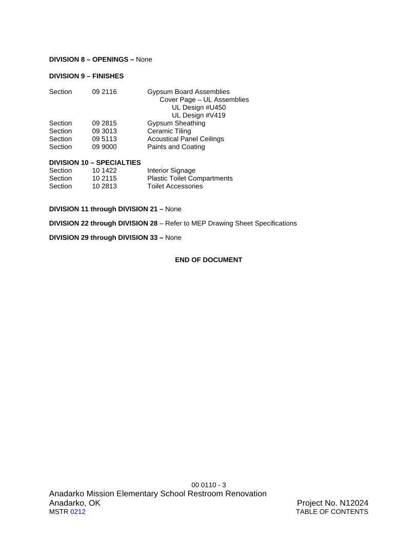
00 0110 - 3 Anadarko Mission Elementary School Restroom Renovation Anadarko, OK Project No. N12024MSTR 0212 TABLE OF CONTENTS
DIVISION 8 – OPENINGS – None DIVISION 9 – FINISHES Section 09 2116 Gypsum Board Assemblies Cover Page – UL Assemblies UL Design #U450 UL Design #V419 Section 09 2815 Gypsum Sheathing Section 09 3013 Ceramic Tiling Section 09 5113 Acoustical Panel Ceilings Section 09 9000 Paints and Coating DIVISION 10 – SPECIALTIES Section 10 1422 Interior Signage Section 10 2115 Plastic Toilet Compartments Section 10 2813 Toilet Accessories
DIVISION 11 through DIVISION 21 – None
DIVISION 22 through DIVISION 28 – Refer to MEP Drawing Sheet Specifications
DIVISION 29 through DIVISION 33 – None
END OF DOCUMENT

00 1101 - 1 Anadarko Mission Elementary School Restroom Renovation Anadarko, OK Project No. N12024 MSTR 0409 ADVERTISEMENT FOR BID
DOCUMENT 00 1101 BWA N12024 ADVERTISEMENT FOR BIDS PART 1 GENERAL FROM: 1.1 OWNER
A. BOARD OF EDUCATION, ISD No. 08i020 ANADARKO PUBLIC SCHOOLS ANADARKO, CADDO COUNTY, OKLAHOMA
1.2 ARCHITECT
A. Boynton Williams & Associates 900 36TH Ave. N.W. Ste.100 Norman, OK 73072
1.3 SOLICITATION DATE
A. August 09, 2012 1.4 PROJECT DESCRIPTION
A. Title: Anadarko Mission Elementary School Bathroom Renovation B. Description: Combination of (2) Existing Restrooms into one and Renovation of old
mechanical room into new Restroom C. Location: Anadarko Public Schools
1400 Warrior Drive Anadarko, OK 74501
D. Bids For: Single Prime Contract. 1.5 BID DATE, TIME AND PLACE
A. Bid Date: Thursday, August 30, 2012 B. Time of Bid: 2 pm, Central Time C. Place of Bid: Superintendent’s Office
Anadarko Public Schools 1400 South Mission Street Anadarko, OK 73005-5813
1.6 POTENTIAL BIDDERS
A. Sealed Bids addressed to Owner will be received at Place of Bid until Time of Bid on Bid Date. Bids will be read publicly same date and hour.
B. Bidders for Work Packages may be required to submit a Contractor’s Qualification Statement as specified in Document 00 2113 - Instructions to Bidders, Article 6.1. Bidders for Work Packages should be prepared to submit Contractor’s Qualification Statement, upon request of Owner. Utilize AIA Form A305 - Contractor’s Qualification Statement.
C. Bidders will be required to provide Bid security in the form of a Bid Bond in the amount of five (5) percent of the bid amount. Refer to Document 00 4313 - Bid Security Form for additional information.
D. Refer to other bidding requirements described in Document 00 2113 - Instructions to Bidders and modifications thereto and Document 00 2218 - Additional Instructions to Bidders.
E. Submit your offer on the Bid Form provided in Project Manual. F. Your Bid will be required to be submitted under a condition of irrevocability for a period of
45 days after submission. G. The Owner reserves the right to waive any informalities and accept or reject any or all bids.

00 1101 - 2 Anadarko Mission Elementary School Restroom Renovation Anadarko, OK Project No. N12024 MSTR 0409 ADVERTISEMENT FOR BID
1.7 OBTAINING BIDDING DOCUMENTS FOR WORK PACKAGES A. Bid Documents for Stipulated Sum Separate Prime Contracts for specified Work Packages
may be obtained from the Reproduction Vendor. Contact the Office of the Architect to reserve Bidding Documents. Bidders may obtain maximum two (2) sets of Bidding Documents.
B. Refundable deposit sum of $50 per set is due to the Architect's Office prior to obtaining Bidding Documents.
C. Submit Deposit in the form of cash or check written on the Bidder’s business account made payable to the Architect. Service charge of $25.00 will be applied for checks returned from bank.
D. Bidders are responsible for arranging pick-up or shipment of Bidding Documents with the Reproduction Vendor. Shipping cost determined by Reproduction Vendor.
E. Return of Bidding Documents and Deposit: 1. Deposits will be refunded to bidders who submit a bona fide Bid at the time and place
designated in this Solicitation and who return the Bidding Documents to the Architect’s Office in good condition within ten (10) calendar days from the Contract Award Date or Bid Rejection Date as indicated by written notification to Bidders by Architect.
2. Deposits will be forfeited by Bidders who do not submit a bona fide Bid or do not return the Bidding Documents in good condition to the Architect’s Office before the Bid Opening Time.
3. Return Bidding Documents to Architect’s Office in person or postage paid. Architect will not accept delivery of Contract Documents returned C.O.D, freight collect or other similar methods.
4. Replacement costs of $3.50 per sheet for Drawings and $0.25 per page for Specifications and Addenda will be deducted from the Bidder’s deposit for missing or damaged Contract Documents.
1.8 SUBCONTRACTOR AND SUPPLIER BIDDING DOCUMENTS
A. Subcontractors and Suppliers may obtain full or partial sets of Bidding Documents by direct purchase from the Reproduction Vendor.
B. All Bidding Documents remain the property of the Architect. The Bidding Documents are on file at the Architect’s Office and are available and open for inspection by Bidders and Sub-bidders on a first-come-first-served basis during normal business hours.
C. Bidders may view the Bid Documents at the Office of the Owner or at local Plan Rooms in OKC: Dodge/AGC, Bid News or Southwest News.
1.9 REPRODUCTION VENDOR
A. Additional copies of Bidding Documents may be obtained by direct purchase from the Reproduction Vendor at the following locations:
Gill Reprographics, Incorporated 7001 North Santa Fe Oklahoma City, Oklahoma 73107 Phone: 405-947-6891 Fax: 405-947-6892
B. Cost for each set or individual page, including shipping and handling determined by vendor. 1.10 QUESTIONS DURING BIDDING
A. For information concerning any part of the proposed Work, contact the Architect as specified in Document 00 2113 - Instructions to Bidders and modifications thereto and Document 00 2218 - Additional Instructions to Bidders.
B. Additional bidding instructions are included in the Bidding Requirements which are bound into the Contract Documents.

00 1101 - 3 Anadarko Mission Elementary School Restroom Renovation Anadarko, OK Project No. N12024 MSTR 0409 ADVERTISEMENT FOR BID
1.11 MANDATORY PRE-BID SITE INVESTIGATION A. Pre-Bid Site Investigation is required to familiarize Bidders with the Work requirements and
with existing conditions of Project Site. B. Contact Owner Representative to schedule a date and time to meet Owner Representative
and investigate the existing site conditions. 1. Owner Representative contact information listed in Document 00 2513 - Pre-Bid
Investigation. 1.12 AUTHORIZATION
A. By: Anadarko Public Schools (08i020)
END OF ADVERTISEMENT FOR BIDS

00 2113 - 1 Anadarko Mission Elementary School Restroom Renovation Anadarko, OK Project No. N12024MSTR 0409 INSTRUCTIONS TO BIDDERS
DOCUMENT 00 2113 BWA N12024 INSTRUCTIONS TO BIDDERS PART 1 GENERAL INSTRUCTIONS TO BIDDERS
A. American Institute of Architects, AIA Document A701 “Instructions to Bidders” and modifications thereto shall be Instructions to Bidders for this Project.
B. Copy of AIA Document A701 follows.
PART 2 PRODUCTS Not Used. PART 3 EXECUTION Not Used.
END OF DOCUMENT

AIA®
Document A701TM – 1997 Instructions to Bidders
AIA Document A701™ – 1997. Copyright © 1970, 1974, 1978, 1987 and 1997 by The American Institute of Architects. All rights reserved. WARNING: This AIA® Document is protected by U.S. Copyright Law and International Treaties. Unauthorized reproduction or distribution of this AIA® Document, or any portion of it, may result in severe civil and criminal penalties, and will be prosecuted to the maximum extent possible under the law. This draft was produced by AIA software at 11:00:19 on 08/06/2008 under Order No.1000341532_1 which expires on 2/3/2009, and is not for resale. User Notes: (4204208058)
1
ADDITIONS AND DELETIONS: The author of this document has added information needed for its completion. The author may also have revised the text of the original AIA standard form. An Additions and Deletions Report that notes added information as well as revisions to the standard form text is available from the author and should be reviewed.
This document has important legal consequences. Consultation with an attorney is encouraged with respect to its completion or modification.
ELECTRONIC COPYING of any portion of this AIA® Document to another electronic file is prohibited and constitutes a violation of copyright laws as set forth in the footer of this document.
for the following PROJECT: (Name and location or address): [Insert Project Name] [Location] [City, ST Zip] THE OWNER: (Name and address): [Insert Owner Name] [Address] [City, ST Zip] THE ARCHITECT: (Name and address): [Insert Architect’s Name] [Address] [City, ST Zip] TABLE OF ARTICLES 1 DEFINITIONS 2 BIDDER'S REPRESENTATIONS 3 BIDDING DOCUMENTS 4 BIDDING PROCEDURES 5 CONSIDERATION OF BIDS 6 POST-BID INFORMATION 7 PERFORMANCE BOND AND PAYMENT BOND 8 FORM OF AGREEMENT BETWEEN OWNER AND CONTRACTOR

AIA Document A701™ – 1997. Copyright © 1970, 1974, 1978, 1987 and 1997 by The American Institute of Architects. All rights reserved. WARNING: This AIA® Document is protected by U.S. Copyright Law and International Treaties. Unauthorized reproduction or distribution of this AIA® Document, or any portion of it, may result in severe civil and criminal penalties, and will be prosecuted to the maximum extent possible under the law. This draft was produced by AIA software at 11:00:19 on 08/06/2008 under Order No.1000341532_1 which expires on 2/3/2009, and is not for resale. User Notes: (4204208058)
2
ARTICLE 1 DEFINITIONS § 1.1 Bidding Documents include the Bidding Requirements and the proposed Contract Documents. The Bidding Requirements consist of the Advertisement or Invitation to Bid Bid Solicitation, Instructions to Bidders, and modifications therto, Supplementary Instructions to Bidders, the bid form Additional Instructions to Bidders, the Bid Form and other sample Bidding and Contract Forms and Documents. The proposed Contract Documents consist of the form of Agreement between the Owner and Contractor, Conditions of the Contract (General, Supplementary and other Conditions), Drawings, Specifications and all Addenda issued prior to execution of the Contract. § 1.2 Definitions set forth in the General Conditions of the Contract for Construction, AIA Document A201, or in other Contract Documents are applicable to the Bidding Documents. § 1.3 Addenda are written or graphic instruments issued by the Architect prior to the execution of the Contract which modify or interpret the Bidding Documents by additions, deletions, clarifications or corrections. 1.3.1 On the day established as the Bid Date in the Bid Solicitation, Addenda may be issued by facsimile. Such Addenda shall be defined as a Fax (Facsimile) Addendum. § 1.4 A Bid is a complete and properly executed proposal to do the Work for the sums stipulated therein, submitted in accordance with the Bidding Documents. § 1.5 The Base Bid is the sum stated in the Bid for which the Bidder offers to perform the Work described in the Bidding Documents as the base, to which Work may be added or from which Work may be deleted for sums stated in Alternate Bids. § 1.6 An Alternate Bid (or Alternate) is an amount stated in the Bid to be added to or deducted from the amount of the Base Bid if the corresponding change in the Work, as described in the Bidding Documents, is accepted. § 1.7 A Unit Price is an amount stated in the Bid as a price per unit of measurement for materials, equipment or services or a portion of the Work as described in the Bidding Documents. § 1.8 A Bidder is a person or entity who submits a Bid and who meets the requirements set forth in the Bidding Documents. § 1.9 A Sub-bidder is a person or entity who submits a bid to a Bidder for materials, equipment or labor for a portion of the Work. ARTICLE 2 BIDDER'S REPRESENTATIONS § 2.1 The Bidder by making a Bid represents that: § 2.1.1 The Bidder and each of his Sub-bidders has read and understands the Bidding Documents or Contract Documents, to the extent that such documentation relates to the Work for which the Bid is submitted, and for other portions of the Project, if any, being bid concurrently or presently under construction. § 2.1.2 The Bid is made in compliance with the Bidding Documents. § 2.1.3 The Bidder has visited the site, become familiar with local conditions under which the Work is to be performed and has correlated the Bidder's personal observations with the requirements of the proposed Contract Documents and has notified each Sub-bidder of the observations and correlations which will effect their portion of the Work. § 2.1.4 The Bid is based upon the materials, equipment and systems required by the Bidding Documents without exception and each Sub-bid upon which the Bid is in part based. 2.2 The Bidder and each Sub-bidder, by making a Bid or a Sub-bid, also represents that the Bidder or Sub-bidder has read and understands the additional representations contained in the proposed Contract Documents and makes representations in accordance therewith.

AIA Document A701™ – 1997. Copyright © 1970, 1974, 1978, 1987 and 1997 by The American Institute of Architects. All rights reserved. WARNING: This AIA® Document is protected by U.S. Copyright Law and International Treaties. Unauthorized reproduction or distribution of this AIA® Document, or any portion of it, may result in severe civil and criminal penalties, and will be prosecuted to the maximum extent possible under the law. This draft was produced by AIA software at 11:00:19 on 08/06/2008 under Order No.1000341532_1 which expires on 2/3/2009, and is not for resale. User Notes: (4204208058)
3
ARTICLE 3 BIDDING DOCUMENTS § 3.1 COPIES § 3.1.1 Bidders may obtain complete sets of the Bidding Documents from the issuing office designated in the Advertisement or Invitation to Bid Bid Solicitation in the number and for the deposit sum, if any, stated therein. The deposit will be refunded to Bidders who submit a bona fide Bid at the time and place designated in the Bid Solicitation and return the Bidding Documents to the office of the Architect, including all Drawings, Specifications and Addenda, in good condition within ten (10) days after receipt of Bids from the Bid Date. Replacement costs for damaged or missing Drawings or pages for Specifications and Addenda will be deducted from the Bidders as outlined in the Advertisement or Invitation to Bid. Deposits will be forfeited by Bidders who do not submit a bona fide Bid or who do not return the Bidding Documents to the office of the Architect in good condition within five (5) days from the date they are received or no later than seven (7) days prior to the bid date. Bidding Documents shall be returned to the Architect’s Office postage paid. The Architect will not accept delivery of Bidding Documents returned C.O.D., freight collect or other similar methods. The cost of replacement of missing or damaged documents will be deducted from the deposit. A Bidder receiving a Contract award may retain the Bidding Documents and the Bidder's deposit will be refunded. 3.1.1.1 A Bidder receiving a Contract Award may retain the Bidding Documents and the Bidder’s deposit will be refunded. § 3.1.2 Bidding Documents will not be issued directly to Sub-bidders unless specifically offered in the Advertisement or Invitation to Bid, or in supplementary instructions to bidders. § 3.1.3 Bidders and Sub-bidders shall use complete sets of Bidding Documents in preparing Bids; neither the Owner nor Architect assumes responsibility for errors or misinterpretations resulting from the use of incomplete sets of Bidding Documents. § 3.1.4 The Owner and Architect may make copies of the Bidding Documents available on the above terms for the purpose of obtaining Bids on the Work. No license or grant of use is conferred by issuance of copies of the Bidding Documents. 3.1.5 Prior to acceptance of a Sub-bid, the Bidder shall insure that the Sub-bidder has read and understands all of the Bidding Documents and has made his Sub-bid in full accordance therewith. § 3.2 INTERPRETATION OR CORRECTION OF BIDDING DOCUMENTS § 3.2.1 The Bidder shall carefully study and compare the Bidding Documents with each other, and with other work being bid concurrently or presently under construction to the extent that it relates to the Work for which the Bid is submitted, shall examine the site and local conditions, and shall at once report to the Architect errors, inconsistencies or ambiguities discovered. § 3.2.2 Bidders and Sub-bidders requiring clarification or interpretation of the Bidding Documents shall make a written request which shall reach the Architect at least seven days prior to the date for receipt of Bids. The Bidder and each Sub-bidder accepts a duty, obligation and responsibility to seek clarification of any open, obvious or patent error or ambiguity in the proposed Contract Documents. § 3.2.3 Interpretations, corrections and changes of the Bidding Documents will be made by Addendum. Interpretations, corrections and changes of the Bidding Documents made in any other manner will not be binding, and Bidders shall not rely upon them. § 3.3 SUBSTITUTIONS § 3.3.1 The materials, products and equipment described in the Bidding Documents establish a standard of required function, dimension, appearance and quality to be met by any proposed substitution. § 3.3.2 No substitution will be considered prior to receipt of Bids unless written request for approval has been received by the Architect at least ten five (5) days prior to the date for receipt of Bids. Such requests shall include the name of the material or equipment for which it is to be substituted and a complete description of the proposed substitution including drawings, performance and test data, and other information necessary for an evaluation. A statement setting forth changes in other materials, equipment or other portions of the Work, including changes in the work of other contracts that incorporation of the proposed substitution would require, shall be included. The burden

AIA Document A701™ – 1997. Copyright © 1970, 1974, 1978, 1987 and 1997 by The American Institute of Architects. All rights reserved. WARNING: This AIA® Document is protected by U.S. Copyright Law and International Treaties. Unauthorized reproduction or distribution of this AIA® Document, or any portion of it, may result in severe civil and criminal penalties, and will be prosecuted to the maximum extent possible under the law. This draft was produced by AIA software at 11:00:19 on 08/06/2008 under Order No.1000341532_1 which expires on 2/3/2009, and is not for resale. User Notes: (4204208058)
4
of proof of the merit of the proposed substitution is upon the proposer. The Architect's decision of approval or disapproval of a proposed substitution shall be final. § 3.3.3 If the Architect approves a proposed substitution prior to receipt of Bids, such approval will be set forth in an Addendum. Bidders shall not rely upon approvals made in any other manner. § 3.3.4 No substitutions will be considered after the Contract award unless specifically provided for in the Contract Documents. § 3.4 ADDENDA § 3.4.1 Addenda will be transmitted to all who are known by the issuing office to have received a complete set of Bidding Documents. 3.4.1.1 A copy of all Fax Addenda will be available to all Bidders at the Place of Bid prior to the Time of Bid as established in the Bid Solicitation. § 3.4.2 Copies of Addenda will be made available for inspection wherever Bidding Documents are on file for that purpose. § 3.4.3 Addenda will be issued no later than four days prior to the date for receipt of Bids except an Addendum withdrawing the request for Bids or one which includes postponement of the date for receipt of Bids. § 3.4.4 Each Bidder shall ascertain prior to submitting a Bid that the Bidder has received all Addenda issued, and the Bidder shall acknowledge their receipt in the Bid. 3.4.5 Each Bidder shall ascertain prior to accepting a bid from a Sub-bidder that the Sub-bidder has reviewed all Addenda and that the Sub-bidder’s bid has been made in accordance with all Addenda. ARTICLE 4 BIDDING PROCEDURES § 4.1 PREPARATION OF BIDS § 4.1.1 Bids shall be submitted on the forms included with the Bidding Documents. § 4.1.2 All blanks on the bid form shall be legibly executed in a non-erasable medium. § 4.1.3 Sums shall be expressed in both words and figures. In case of discrepancy, the amount written in words shall govern. § 4.1.4 Interlineations, alterations and erasures must be initialed by the signer of the Bid. § 4.1.5 All requested Alternates shall be bid. If no change in the Base Bid is required, enter "No Change." § 4.1.6 Where two or more Bids for designated portions of the Work have been requested, the Bidder may, without forfeiture of the bid security, state the Bidder's refusal to accept award of less than the combination of Bids stipulated by the Bidder. The Bidder shall make no additional stipulations on the bid form nor qualify the Bid in any other manner. § 4.1.7 Each copy of the Bid shall state the legal name of the Bidder and the nature of legal form of the Bidder. The Bidder shall provide evidence of legal authority to perform within the jurisdiction of the Work. Each copy shall be signed by the person or persons legally authorized to bind the Bidder to a contract. A Bid by a corporation shall further give the state of incorporation and have the corporate seal affixed. A Bid submitted by an agent shall have a current power of attorney attached certifying the agent's authority to bind the Bidder. 4.1.8 The Bidder shall make no stipulations on the Bid Form nor qualify the Bid in any other manner. § 4.2 BID SECURITY § 4.2.1 Each Bid shall be accompanied by a bid security in the form and amount required if so stipulated in the Instructions to Bidders. The Bidder pledges to enter into a Contract with the Owner on the terms stated in the Bid and will, if required, furnish bonds covering the faithful performance of the Contract and payment of all obligations

AIA Document A701™ – 1997. Copyright © 1970, 1974, 1978, 1987 and 1997 by The American Institute of Architects. All rights reserved. WARNING: This AIA® Document is protected by U.S. Copyright Law and International Treaties. Unauthorized reproduction or distribution of this AIA® Document, or any portion of it, may result in severe civil and criminal penalties, and will be prosecuted to the maximum extent possible under the law. This draft was produced by AIA software at 11:00:19 on 08/06/2008 under Order No.1000341532_1 which expires on 2/3/2009, and is not for resale. User Notes: (4204208058)
5
arising thereunder. Should the Bidder refuse to enter into such Contract or fail to furnish such bonds if required, the amount of the bid security shall be forfeited to the Owner as liquidated damages, not as a penalty. The amount of the bid security shall not be forfeited to the Owner in the event the Owner fails to comply with Section 6.2. § 4.2.2 If a surety bond is required, it shall be written on AIA Document A310, Bid Bond, unless otherwise provided in the Bidding Documents, and the attorney-in-fact who executes the bond on behalf of the surety shall affix to the bond a certified and current copy of the power of attorney. § 4.2.3 The Owner will have the right to retain the bid security of Bidders to whom an award is being considered until either (a) the Contract has been executed and bonds, if required, have been furnished, or (b) the specified time has elapsed so that Bids may be withdrawn or (c) all Bids have been rejected. § 4.3 SUBMISSION OF BIDS § 4.3.1 All copies of the Bid, the bid security, if any, and any other documents required to be submitted with the Bid shall be enclosed in a sealed opaque envelope. The envelope shall be addressed to the party receiving the Bids and shall be identified with the Project name, the Bidder's name and address and, if applicable, the designated portion of the Work for which the Bid is submitted. If the Bid is sent by mail, the sealed envelope shall be enclosed in a separate mailing envelope with the notation "SEALED BID ENCLOSED" on the face thereof. § 4.3.2 Bids shall be deposited at the designated location prior to the time and date for receipt of Bids. Bids received after the time and date for receipt of Bids will be returned unopened. § 4.3.3 The Bidder shall assume full responsibility for timely delivery at the location designated for receipt of Bids. The Bidder shall assume full and sole responsibility for communications between the Bidder’s office and a representative of the Bidder who hand delivers the Bid to the Place of Bid. § 4.3.4 Oral, telephonic, telegraphic, facsimile or other electronically transmitted bids will not be considered. § 4.4 MODIFICATION OR WITHDRAWAL OF BID § 4.4.1 A Bid may not be modified, withdrawn or canceled by the Bidder during the stipulated time period following the time and date designated for the receipt of Bids, and each Bidder so agrees in submitting a Bid. § 4.4.2 Prior to the time and date designated for receipt of Bids, a Bid submitted may be modified or withdrawn by notice to the party receiving Bids at the place designated for receipt of Bids. Such notice shall be in writing over the signature of the Bidder. Written confirmation over the signature of the Bidder shall be received, and date- and time-stamped by the receiving party on or before the date and time set for receipt of Bids. A change shall be so worded as not to reveal the amount of the original Bid. § 4.4.3 Withdrawn Bids may be resubmitted up to the date and time designated for the receipt of Bids provided that they are then fully in conformance with these Instructions to Bidders. § 4.4.4 Bid security, if required, shall be in an amount sufficient for the Bid as resubmitted. ARTICLE 5 CONSIDERATION OF BIDS § 5.1 OPENING OF BIDS At the discretion of the Owner, if stipulated in the Advertisement or Invitation to Bid, the properly identified Bids received on time will be publicly opened and will be read aloud. An abstract of the Bids may be made available to Bidders. § 5.2 REJECTION OF BIDS The Owner shall have the right to reject any or all Bids. A Bid not accompanied by a required bid security or by other data required by the Bidding Documents, or a Bid which is in any way incomplete or irregular is subject to rejection. § 5.3 ACCEPTANCE OF BID (AWARD) § 5.3.1 It is the intent of the Owner to award a Contract to the lowest qualified Bidder provided the Bid has been submitted in accordance with the requirements of the Bidding Documents and does not exceed the funds available.
AIA Document A701™ – 1997. Copyright © 1970, 1974, 1978, 1987 and 1997 by The American Institute of Architects. All rights reserved. WARNING: This AIA® Document is protected by U.S. Copyright Law and International Treaties. Unauthorized reproduction or distribution of this AIA® Document, or any portion of it, may result in severe civil and criminal penalties, and will be prosecuted to the maximum extent possible under the law. This draft was produced by AIA software at 11:00:19 on 08/06/2008 under Order No.1000341532_1 which expires on 2/3/2009, and is not for resale. User Notes: (4204208058)
6
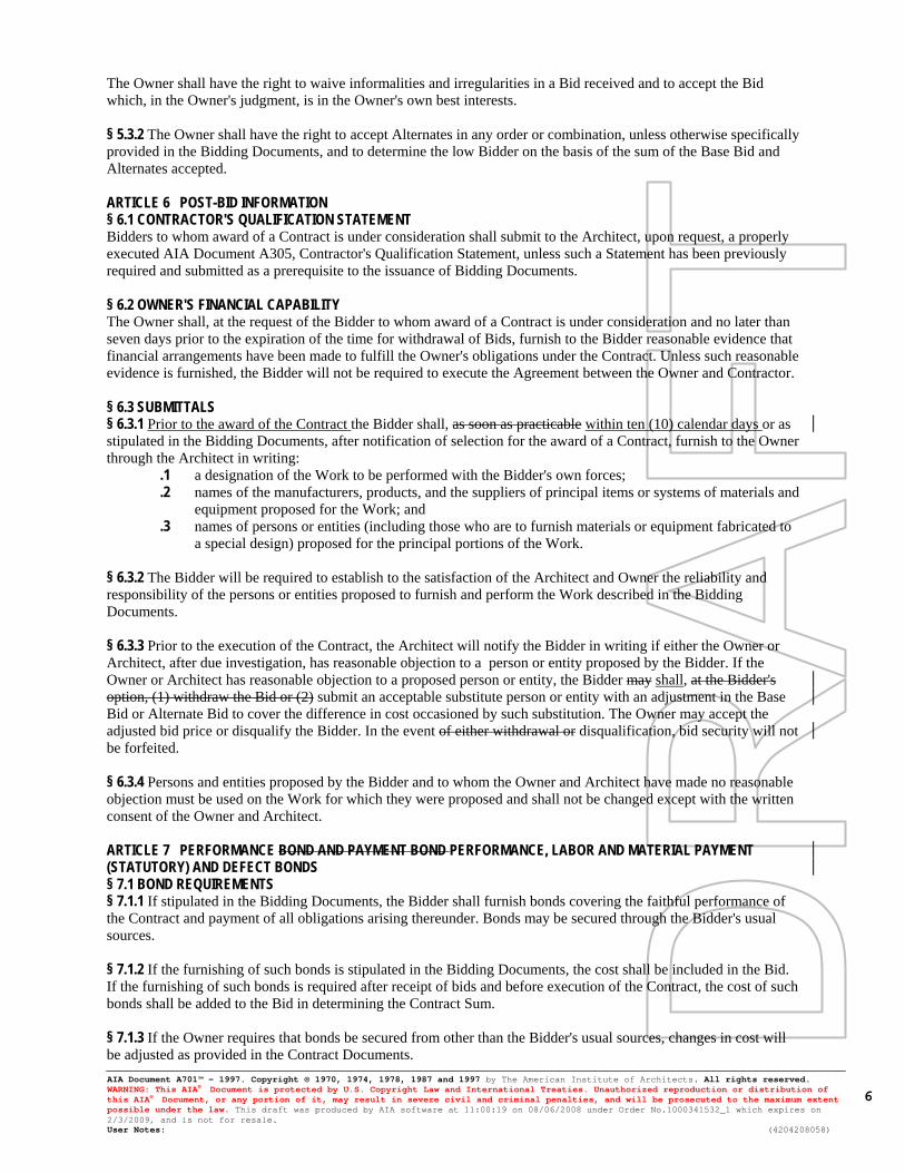
The Owner shall have the right to waive informalities and irregularities in a Bid received and to accept the Bid which, in the Owner's judgment, is in the Owner's own best interests. § 5.3.2 The Owner shall have the right to accept Alternates in any order or combination, unless otherwise specifically provided in the Bidding Documents, and to determine the low Bidder on the basis of the sum of the Base Bid and Alternates accepted. ARTICLE 6 POST-BID INFORMATION § 6.1 CONTRACTOR'S QUALIFICATION STATEMENT Bidders to whom award of a Contract is under consideration shall submit to the Architect, upon request, a properly executed AIA Document A305, Contractor's Qualification Statement, unless such a Statement has been previously required and submitted as a prerequisite to the issuance of Bidding Documents. § 6.2 OWNER'S FINANCIAL CAPABILITY The Owner shall, at the request of the Bidder to whom award of a Contract is under consideration and no later than seven days prior to the expiration of the time for withdrawal of Bids, furnish to the Bidder reasonable evidence that financial arrangements have been made to fulfill the Owner's obligations under the Contract. Unless such reasonable evidence is furnished, the Bidder will not be required to execute the Agreement between the Owner and Contractor. § 6.3 SUBMITTALS § 6.3.1 Prior to the award of the Contract the Bidder shall, as soon as practicable within ten (10) calendar days or as stipulated in the Bidding Documents, after notification of selection for the award of a Contract, furnish to the Owner through the Architect in writing:
.1 a designation of the Work to be performed with the Bidder's own forces;
.2 names of the manufacturers, products, and the suppliers of principal items or systems of materials and equipment proposed for the Work; and
.3 names of persons or entities (including those who are to furnish materials or equipment fabricated to a special design) proposed for the principal portions of the Work.
§ 6.3.2 The Bidder will be required to establish to the satisfaction of the Architect and Owner the reliability and responsibility of the persons or entities proposed to furnish and perform the Work described in the Bidding Documents. § 6.3.3 Prior to the execution of the Contract, the Architect will notify the Bidder in writing if either the Owner or Architect, after due investigation, has reasonable objection to a person or entity proposed by the Bidder. If the Owner or Architect has reasonable objection to a proposed person or entity, the Bidder may shall, at the Bidder's option, (1) withdraw the Bid or (2) submit an acceptable substitute person or entity with an adjustment in the Base Bid or Alternate Bid to cover the difference in cost occasioned by such substitution. The Owner may accept the adjusted bid price or disqualify the Bidder. In the event of either withdrawal or disqualification, bid security will not be forfeited. § 6.3.4 Persons and entities proposed by the Bidder and to whom the Owner and Architect have made no reasonable objection must be used on the Work for which they were proposed and shall not be changed except with the written consent of the Owner and Architect. ARTICLE 7 PERFORMANCE BOND AND PAYMENT BOND PERFORMANCE, LABOR AND MATERIAL PAYMENT (STATUTORY) AND DEFECT BONDS § 7.1 BOND REQUIREMENTS § 7.1.1 If stipulated in the Bidding Documents, the Bidder shall furnish bonds covering the faithful performance of the Contract and payment of all obligations arising thereunder. Bonds may be secured through the Bidder's usual sources. § 7.1.2 If the furnishing of such bonds is stipulated in the Bidding Documents, the cost shall be included in the Bid. If the furnishing of such bonds is required after receipt of bids and before execution of the Contract, the cost of such bonds shall be added to the Bid in determining the Contract Sum. § 7.1.3 If the Owner requires that bonds be secured from other than the Bidder's usual sources, changes in cost will be adjusted as provided in the Contract Documents.

AIA Document A701™ – 1997. Copyright © 1970, 1974, 1978, 1987 and 1997 by The American Institute of Architects. All rights reserved. WARNING: This AIA® Document is protected by U.S. Copyright Law and International Treaties. Unauthorized reproduction or distribution of this AIA® Document, or any portion of it, may result in severe civil and criminal penalties, and will be prosecuted to the maximum extent possible under the law. This draft was produced by AIA software at 11:00:19 on 08/06/2008 under Order No.1000341532_1 which expires on 2/3/2009, and is not for resale. User Notes: (4204208058)
7
§ 7.2 TIME OF DELIVERY AND FORM OF BONDS § 7.2.1 The Bidder shall deliver the required bonds to the Owner not later than three days following the date of execution of the Contract. If the Work is to be commenced prior thereto in response to a letter of intent, the Bidder shall, prior to commencement of the Work, submit evidence satisfactory to the Owner that such bonds will be furnished and delivered in accordance with this Section 7.2.1. § 7.2.2 Unless otherwise provided, the bonds shall be written on AIA Document A312, Performance Bond and Payment Bond. Both bonds shall be written in the amount of the Contract Sum. The Defect Bond shall be written on the form included in the Contract Documents and shall be written in the amount of the Contract Sum. § 7.2.3 The bonds shall be dated on or after the date of the Contract. § 7.2.4 The Bidder shall require the attorney-in-fact who executes the required bonds on behalf of the surety to affix thereto a certified and current copy of the power of attorney. ARTICLE 8 FORM OF AGREEMENT BETWEEN OWNER AND CONTRACTOR Unless otherwise required in the Bidding Documents, the Agreement for the Work will be written on AIA Document A101, Standard Form of Agreement Between Owner and Contractor Where the Basis of Payment Is a Stipulated Sum.

00 2218 - 1 Anadarko Mission Elementary School Restroom Renovation Anadarko, OK Project No. N12024 MSTR 0409 ADDITIONAL INSTRUCTIONS TO BIDDERS
DOCUMENT 00 2218 BWA N12024 ADDITIONAL INSTRUCTIONS TO BIDDERS PART 1 GENERAL 1.1 SUMMARY
A. Section Includes: 1. Definitions. 2. Qualifications of bidders. 3. Number of contracts. 4. Time for completion. 5. Interpretation or Correction of Bidding Documents. 6. Substitutions. 7. Bid forms. 8. Beginning the Work. 9. Compliance with Public Competitive Bidding Act.
B. Related Documents:
1. The Contract Documents, as defined in Document 00 7213 - General Conditions and modifications thereto, apply to the Work of this Section. Additional requirements and information necessary to complete the Work of this Section may be found in other documents. a. Document 00 2113 - Instructions to Bidders and modifications thereto:
Requirements and procedures for bidding. b. Document 00 7213 - General Conditions: Substitution requirements.
C. Related Sections:
1. Section 01 4200 - References: Definitions. 2. Section 01 6200 - Product Options: Substitution requirements.
1.2 DEFINITIONS
A. Refer to Document 00 2113 - Instructions to Bidders, 00 7213 - General Conditions, and Section 01 4200 - References for definitions.
1.3 QUALIFICATIONS OF BIDDERS
A. Bidders must be regularly engaged in the business of Commercial Construction as defined for building construction under Title 40, Oklahoma Statutes, Section 196.6, Paragraph A.1.
B. Sub-bidders must be regularly engaged in the business or trade for that portion of the Work proposed in their Sub-bid to a Bidder.
1.4 NUMBER OF CONTRACTS
A. One (1) contract will be awarded for all Work as defined in the proposed Contract Documents to include, but not be limited to, general construction, mechanical Work and electrical Work.
B. Where the Contract Documents show various particular items of the Work to be Not
Included in the Contract (noted N.I.C.), that Work will be accomplished by the Owner after the Contractor achieves the status of Substantial Completion.

00 2218 - 2 Anadarko Mission Elementary School Restroom Renovation Anadarko, OK Project No. N12024 MSTR 0409 ADDITIONAL INSTRUCTIONS TO BIDDERS
C. Where the Contract Documents require Owner furnished and installed items, those items will be installed after the Contractor achieves the status of Substantial Completion.
D. Bidders must submit a Bid which covers all of the Work proposed in the Contract
Documents. 1.5 INTERPRETATION OR CORRECTION OF BIDDING DOCUMENTS
A. Refer to Paragraph 3.2 of Document 00 2113 - Instructions to Bidders for additional requirements.
B. Bidders shall promptly notify the Architect of any ambiguity, inconsistency or error which
they may discover upon examination of the Bidding Documents. Request for clarification or interpretation of the Bidding Documents shall be made in writing on Contractor’s Letterhead to the Architect.
C. Interpretations, corrections or changes of the Bidding Documents will be made by
Addendum ONLY. Information transmitted in any other manner will not be binding and Bidders shall not rely upon its accuracy.
D. Addenda are written or graphic instruments issued by the Architect before the execution of
the Contract which modify or interpret the Bidding Documents by addition, deletion, clarification or correction. Addenda will be issued to each Bidder receiving complete set of Bidding Documents. Each Bidder shall acknowledge receipt of addenda on the Proposal.
E. The Architect and Owner will not be responsible for any explanations or verbal
interpretations of the Bidding Documents. 1.6 SUBSTITUTIONS
A. Refer to Paragraph 3.3 of Document 00 2113 - Instructions to Bidders for additional
requirements.
B. Refer to Subparagraph 3.4.2 of Document 00 7213 – General Conditions for additional requirements.
C. The materials, products and equipment described in the Bidding Documents establish a
standard of required function, dimension, appearance and quality to be met by any proposed substitution.
D. Provide data on a Contractor’s Substitution Request Form in compliance with the
requirements specified in Section 01 6200 - Product Options.
E. The burden of proof of the merit of the proposed substitute is upon the proposer. The Architect's decision of approval or disapproval of a proposed substitution shall be final.
1.7 BID FORMS
A. Bid Form Proposal Packet: Submit Proposal Packet sealed in envelope labeled as follows.
BID DOCUMENTS Project: Attention:
00 2218 - 3 Anadarko Mission Elementary School Restroom Renovation Anadarko, OK Project No. N12024 MSTR 0409 ADDITIONAL INSTRUCTIONS TO BIDDERS
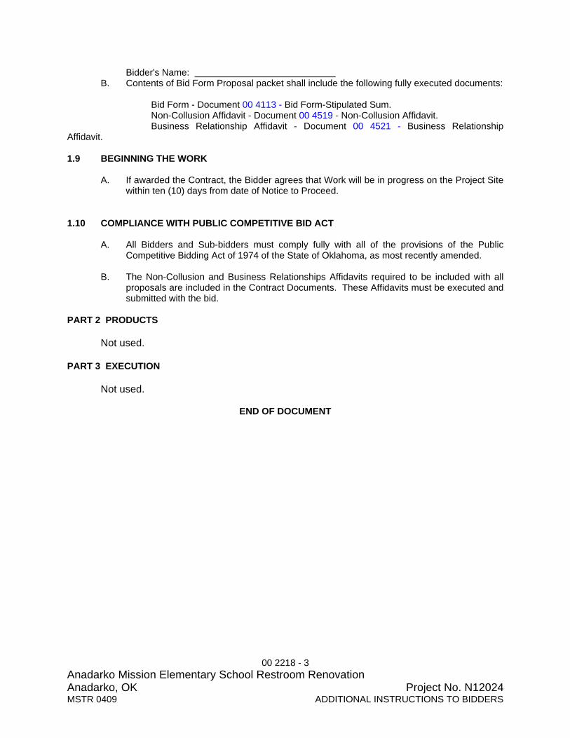
Bidder's Name: B. Contents of Bid Form Proposal packet shall include the following fully executed documents:
Bid Form - Document 00 4113 - Bid Form-Stipulated Sum. Non-Collusion Affidavit - Document 00 4519 - Non-Collusion Affidavit. Business Relationship Affidavit - Document 00 4521 - Business Relationship Affidavit. 1.9 BEGINNING THE WORK
A. If awarded the Contract, the Bidder agrees that Work will be in progress on the Project Site within ten (10) days from date of Notice to Proceed.
1.10 COMPLIANCE WITH PUBLIC COMPETITIVE BID ACT
A. All Bidders and Sub-bidders must comply fully with all of the provisions of the Public Competitive Bidding Act of 1974 of the State of Oklahoma, as most recently amended.
B. The Non-Collusion and Business Relationships Affidavits required to be included with all
proposals are included in the Contract Documents. These Affidavits must be executed and submitted with the bid.
PART 2 PRODUCTS Not used. PART 3 EXECUTION Not used.
END OF DOCUMENT

00 4113 - 1 Anadarko Mission Elementary School Restroom Renovation Anadarko, OK Project No. N12024MSTR 1010 BID FORM-STIPULATED SUM
DOCUMENT 00 4113 BWA N12024 BID FORM-STIPULATED SUM
PROPOSAL FOR: ANADARKO PUBLIC SCHOOLS MISSSION ELEMENTARY RESTROOM RENOVATIONS
OWNER: ANADARKO BOARD OF EDUCATION, ISD #08I020 ANADARKO PUBLIC SCHOOLS ANADARKO, CADDO COUNTY, OKLAHOMA 73005
ARCHITECT: BOYNTON WILLIAMS & ASSOCIATES, INC. 900 36th AVENUE NW, SUITE 100 NORMAN, OKLAHOMA 73072 Phone: 405-329-0423 Fax: 405-364-1439
CONTRACTOR: ______________________________________________ (Print full Company Name)
SCOPE It is understood that the Work included under this Proposal includes all General Construction, Mechanical & Electrical Work and all other Work described in the Bidding Documents to be coordinated and completed during periods when school may be in session to be bid as two separate Prime Contracts.
No sales tax is to be included in the bid for any tangible personal property that will become a part of or incorporated into the Work, as specified in Document 00 7390 - Sales Tax Exemption/Designation of Purchasing Agent.
OFFER The undersigned, as Bidder, in compliance with the Bid Solicitation, Supplementary Instructions to Bidders and Additional Instructions to Bidders, declares that Bidder has examined each Project Site(s) and has become fully informed of all conditions of Project Site(s) and area surrounding each Project Site where Work will be performed, that Bidder has examined and become familiar with all Bidding Documents prepared by Architect and that Bidder understands the Work to be performed. Bidder proposes and agrees to furnish all necessary labor, materials, tools, equipment and supplies, and all other items required for the Work indicated in the Bidding Documents within the time schedule indicated, for either or both of the Base Bids or Combined Bid as indicated by the completion of the amounts, figures and calendar days completed below:
BASE BID – Anadarko Mission Elementary Restroom Renovation
To furnish all labor, materials & general requirement in accordance with the Bidding Documents for the Renovation of Existing Restroom and Old Mechanical Room into new Restroom Pair for the sum of:
_____________________________________________________Dollars. (WRITTEN)
($___________________________) (FIGURES)
{Base Bid to include a Project Contingency Amount of ($5,000.00), refer to 01 2100 Allowances}
CONTRACT TIME If Awarded the Contract, the undersigned Bidder agrees to complete the Work within the following number of calendar days from the Date of Commencement established in the Notice to Proceed:
Calendar Days

00 4113 - 2 Anadarko Mission Elementary School Restroom Renovation Anadarko, OK Project No. N12024MSTR 1010 BID FORM-STIPULATED SUM
ACCEPTANCE This bid shall be open to acceptance and is irrevocable for 45 calendar days from the bid opening date. If this bid is accepted by Owner within time period indicated above, bidder will:
Execute the Agreement to perform the Work indicated within seven (7) working days from date of receipt of Agreement and return executed Agreement Package within 10 working days from date of receipt of Agreement.
Furnish required bonds and insurance certificates attached to Contractor executed Agreement form in amounts and format specified in Document 00 6100 - Bonds, Document 00 7213 - General Conditions, and Document 00 7316 - Insurance Requirements.
Begin work within 10 calendar days from date of written Notice to Proceed.
If this bid is accepted within time stated, and bidder fails to commence the Work or bidder fails to provide required bonds and insurance, the bid security shall be forfeited as damages to Owner by reason of bidder’s failure, limited in amount to the lesser of face value of bid security amount or the difference between this bid and the bid upon which a Contract is signed. If bid is not accepted within time stated above, bid security shall be returned to bidder, in accordance with provisions of Instructions to Bidders; unless a mutually satisfactory arrangement is made for its retention and validity for an extended period of time. ADDENDA The undersigned Bidder acknowledges the receipt of Addenda, issued during the time of bidding, and the several clarifications, modifications and changes included therein are included in this Proposal. Addendum No. ____ Dated: _______________ Addendum No. ____ Dated: _______________ Addendum No. ____ Dated: _______________ Addendum No. ____ Dated: _______________ Addendum No. ____ Dated: _______________ PRE-BID SITE INVESTIGATION CERTIFICATION The undersigned certifies the Mandatory Pre-Bid Site Investigation was performed at _____ AM/PM on ____________ , ____ , 2012. BID PACKAGE The undersigned have attached to this bid the following items required by Instructions to Bidders, Supplementary Instructions to Bidders and Additional Instructions to Bidders. 1. All signatures shall be in Blue Ink to clearly identify Bid Form as an original signed document. 2. Bid Security Form (Required for bids exceeding $50,000). 3. Non Collusion Affidavit. 4. Business Relationship Affidavit.
00 4113 - 3 Anadarko Mission Elementary School Restroom Renovation Anadarko, OK Project No. N12024MSTR 1010 BID FORM-STIPULATED SUM
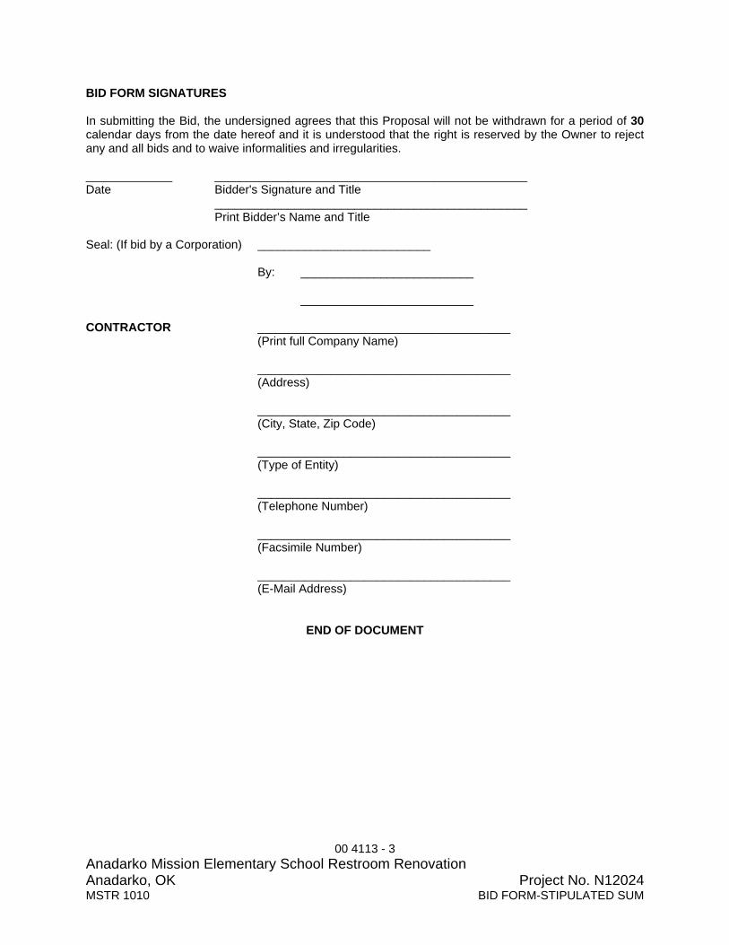
BID FORM SIGNATURES In submitting the Bid, the undersigned agrees that this Proposal will not be withdrawn for a period of 30 calendar days from the date hereof and it is understood that the right is reserved by the Owner to reject any and all bids and to waive informalities and irregularities. _____________ _______________________________________________ Date Bidder's Signature and Title _______________________________________________ Print Bidder’s Name and Title Seal: (If bid by a Corporation) __________________________
By: __________________________
__________________________ CONTRACTOR ______________________________________ (Print full Company Name) ______________________________________ (Address) ______________________________________ (City, State, Zip Code) ______________________________________ (Type of Entity) ______________________________________ (Telephone Number) ______________________________________ (Facsimile Number) ______________________________________ (E-Mail Address)
END OF DOCUMENT

00 4313 - 1 Anadarko Mission Elementary School Restroom Renovation Anadarko, OK Project No. N12024MSTR 0409 BID SECURITY FORM
DOCUMENT 004313 BWA N12024 BID SECURITY FORM PART 1 GENERAL 1.1 BID SECURITY
A. Bid Security required for Projects with Bid Amounts exceeding $50,000.
B. A Bid Security in the form of a cashier's check, or certified check, or acceptable bidder's surety bond, made payable to the Owner, in an amount that is not less than 5 percent of the Bid Proposal submitted, including all alternates, shall accompany each Bid as a guarantee that: 1. The Bidder will not modify, withdraw or cancel the proposal for 45 days after the bid
date, 2. The bidder, if awarded the contract, will promptly enter into a contract and execute
such bonds and furnish such insurance certificates as may be required; and 3. The bidder will provide Non-Collusion and Business Relationship Affidavits.
B. Should the Bidder fail to honor these three (3) guarantees for any reason, the Owner shall
total his damages and shall deduct the amount of such damages from the Bidder's Bid Security. Should the damages total less than the amount of the Bid Security, the difference shall be returned to the Bidder. However, all damages in excess of the Bid Security shall be borne by the Owner.
C. Damages may include, but shall not be limited to, reasonable compensation for the
Owner's additional time spent, additional Architect's fees, costs to the Owner for delays in completion of the Work based upon the Bidders proposed Contract Time and the Contract Time as Awarded including, but not limited to, interest expense and lost revenue, the difference between the Bidder's proposed Contract Sum and the Contract Sum as awarded and costs to rebid the Project should such action become necessary. Such bid securities will be returned to the unsuccessful bidders after execution of the Contract.
1.2 BID SECURITY FORM
A. American Institute of Architects, AIA Document A310 “Bid Bond” 1970 Edition, shall be Bid Security Form for this Project.
B. Copy of AIA Document A310 follows.
C. Surety company standard Bid Security Form also acceptable as long as it contains same
information as AIA Document A310. PART 2 PRODUCTS Not Used. PART 3 EXECUTION Not Used.
END OF DOCUMENT

00 4313 - 2 Anadarko Mission Elementary School Restroom Renovation Anadarko, OK Project No. N12024MSTR 0409 BID SECURITY FORM
REPLACE THIS PAGE
WITH PDF
COPY OF AIA DOCUMENT A310
(Printout of Electronic Format Copy)
“Bid Bond”
00 4513 - 1 Anadarko Mission Elementary School Restroom Renovation Anadarko, OK Project No. N12024MSTR 0409 BIDDER’S QUALIFICATIONS
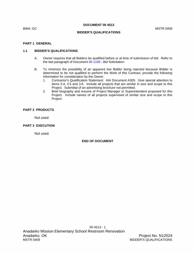
DOCUMENT 00 4513 BWA: GC MSTR 0409 BIDDER’S QUALIFICATIONS PART 1 GENERAL 1.1 BIDDER’S QUALIFICATIONS
A. Owner requires that all Bidders be qualified before or at time of submission of bid. Refer to the last paragraph of Document 00 1100 - Bid Solicitation.
B. To minimize the possibility of an apparent low Bidder being rejected because Bidder is
determined to be not qualified to perform the Work of this Contract, provide the following information for consideration by the Owner. 1. Contractor’s Qualification Statement: AIA Document A305. Give special attention to
items 3.4, 3.5 and 3.6. Include all projects that are similar in size and scope to this Project. Submittal of an advertising brochure not permitted.
2. Brief biography and resume of Project Manager or Superintendent proposed for this Project. Include names of all projects supervised of similar size and scope to this Project.
PART 2 PRODUCTS Not used. PART 3 EXECUTION Not used.
END OF DOCUMENT

Document A305TM – 1986 Contractor's Qualification Statement
AIA Document A305™ – 1986. Copyright © 1964, 1969, 1979 and 1986 by The American Institute of Architects. All rights reserved. WARNING: This AIA® Document is protected by U.S. Copyright Law and International Treaties. Unauthorized reproduction or distribution of this AIA® Document, or any portion of it, may result in severe civil and criminal penalties, and will be prosecuted to the maximum extent possible under the law. This document was produced by AIA software at 14:55:35 on 11/02/2009 under Order No.8360117033_1 which expires on 06/29/2010, and is not for resale. User Notes: (860370278)
1
ADDITIONS AND DELETIONS: The author of this document has added information needed for its completion. The author may also have revised the text of the original AIA standard form. An Additions and Deletions Report that notes added information as well as revisions to the standard form text is available from the author and should be reviewed. A vertical line in the left margin of this document indicates where the author has added necessary information and where the author has added to or deleted from the original AIA text.
This document has important legal consequences. Consultation with an attorney is encouraged with respect to its completion or modification.
This form is approved and recommended by the American Institute of Architects (AIA) and The Associated General Contractors of America (AGC) for use in evaluating the qualifications of contractors. No endorsement of the submitting party or verification of the information is made by AIA or AGC.
The Undersigned certifies under oath that the information provided herein is true and sufficiently complete so as not to be misleading. SUBMITTED TO: ADDRESS: SUBMITTED BY: NAME: ADDRESS: PRINCIPAL OFFICE: [ ] Corporation
[ ] Partnership
[ ] Individual
[ ] Joint Venture
[ ] Other
NAME OF PROJECT (if applicable): 00 TYPE OF WORK (file separate form for each Classification of Work): [ ] General Construction
[ ] HVAC
[ ] Electrical
[ ] Plumbing
[ ] Other (please specify)
§ 1. ORGANIZATION § 1.1 How many years has your organization been in business as a Contractor? § 1.2 How many years has your organization been in business under its present business name?
§ 1.2.1 Under what other or former names has your organization operated?
§ 1.3 If your organization is a corporation, answer the following:
§ 1.3.1 Date of incorporation: § 1.3.2 State of incorporation: § 1.3.3 President’s name:
AIA Document A305™ – 1986. Copyright © 1964, 1969, 1979 and 1986 by The American Institute of Architects. All rights reserved. WARNING: This AIA® Document is protected by U.S. Copyright Law and International Treaties. Unauthorized reproduction or distribution of this AIA® Document, or any portion of it, may result in severe civil and criminal penalties, and will be prosecuted to the maximum extent possible under the law. This document was produced by AIA software at 14:55:35 on 11/02/2009 under Order No.8360117033_1 which expires on 06/29/2010, and is not for resale. User Notes: (860370278)
2
§ 1.3.4 Vice-president’s name(s) § 1.3.5 Secretary’s name: § 1.3.6 Treasurer’s name:
§ 1.4 If your organization is a partnership, answer the following:
§ 1.4.1 Date of organization: § 1.4.2 Type of partnership (if applicable): § 1.4.3 Name(s) of general partner(s)
§ 1.5 If your organization is individually owned, answer the following:
§ 1.5.1 Date of organization: § 1.5.2 Name of owner:
§ 1.6 If the form of your organization is other than those listed above, describe it and name the principals: § 2. LICENSING § 2.1 List jurisdictions and trade categories in which your organization is legally qualified to do business, and indicate registration or license numbers, if applicable. § 2.2 List jurisdictions in which your organization’s partnership or trade name is filed. § 3. EXPERIENCE § 3.1 List the categories of work that your organization normally performs with its own forces. § 3.2 Claims and Suits. (If the answer to any of the questions below is yes, please attach details.)
§ 3.2.1 Has your organization ever failed to complete any work awarded to it? § 3.2.2 Are there any judgments, claims, arbitration proceedings or suits pending or outstanding against your
organization or its officers? § 3.2.3 Has your organization filed any law suits or requested arbitration with regard to construction contracts
within the last five years?
§ 3.3 Within the last five years, has any officer or principal of your organization ever been an officer or principal of another organization when it failed to complete a construction contract? (If the answer is yes, please attach details.)

AIA Document A305™ – 1986. Copyright © 1964, 1969, 1979 and 1986 by The American Institute of Architects. All rights reserved. WARNING: This AIA® Document is protected by U.S. Copyright Law and International Treaties. Unauthorized reproduction or distribution of this AIA® Document, or any portion of it, may result in severe civil and criminal penalties, and will be prosecuted to the maximum extent possible under the law. This document was produced by AIA software at 14:55:35 on 11/02/2009 under Order No.8360117033_1 which expires on 06/29/2010, and is not for resale. User Notes: (860370278)
3
§ 3.4 On a separate sheet, list major construction projects your organization has in progress, giving the name of project, owner, architect, contract amount, percent complete and scheduled completion date.
§ 3.4.1 State total worth of work in progress and under contract:
§ 3.5 On a separate sheet, list the major projects your organization has completed in the past five years, giving the name of project, owner, architect, contract amount, date of completion and percentage of the cost of the work performed with your own forces.
§ 3.5.1 State average annual amount of construction work performed during the past five years:
§ 3.6 On a separate sheet, list the construction experience and present commitments of the key individuals of your organization. § 4. REFERENCES § 4.1 Trade References: § 4.2 Bank References: § 4.3 Surety:
§ 4.3.1 Name of bonding company: § 4.3.2 Name and address of agent:
§ 5. FINANCING § 5.1 Financial Statement.
§ 5.1.1 Attach a financial statement, preferably audited, including your organization’s latest balance sheet and income statement showing the following items:
Current Assets (e.g., cash, joint venture accounts, accounts receivable, notes receivable, accrued income, deposits, materials inventory and prepaid expenses); Net Fixed Assets; Other Assets;
AIA Document A305™ – 1986. Copyright © 1964, 1969, 1979 and 1986 by The American Institute of Architects. All rights reserved. WARNING: This AIA® Document is protected by U.S. Copyright Law and International Treaties. Unauthorized reproduction or distribution of this AIA® Document, or any portion of it, may result in severe civil and criminal penalties, and will be prosecuted to the maximum extent possible under the law. This document was produced by AIA software at 14:55:35 on 11/02/2009 under Order No.8360117033_1 which expires on 06/29/2010, and is not for resale. User Notes: (860370278)
4
Current Liabilities (e.g., accounts payable, notes payable, accrued expenses, provision for income taxes, advances, accrued salaries and accrued payroll taxes); Other Liabilities (e.g., capital, capital stock, authorized and outstanding shares par values, earned surplus and retained earnings).
§ 5.1.2 Name and address of firm preparing attached financial statement, and date thereof: § 5.1.3 Is the attached financial statement for the identical organization named on page one? § 5.1.4 If not, explain the relationship and financial responsibility of the organization whose financial
statement is provided (e.g., parent-subsidiary).
§ 5.2 Will the organization whose financial statement is attached act as guarantor of the contract for construction? § 6. SIGNATURE § 6.1 Dated at this day of
Name of Organization: By: Title:
§ 6.2 M being duly sworn deposes and says that the information provided herein is true and sufficiently complete so as not to be misleading.
Subscribed and sworn before me this day of Notary Public: My Commission Expires:

Additions and Deletions Report for AIA
®
Document A305TM – 1986 This Additions and Deletions Report, as defined on page 1 of the associated document, reproduces below all text the author has added to the standard form AIA document in order to complete it, as well as any text the author may have added to or deleted from the original AIA text. Added text is shown underlined. Deleted text is indicated with a horizontal line through the original AIA text.
Note: This Additions and Deletions Report is provided for information purposes only and is not incorporated into or constitute any part of the associated AIA document. This Additions and Deletions Report and its associated document were generated simultaneously by AIA software at 14:55:35 on 11/02/2009.
Additions and Deletions Report for AIA Document A305™ – 1986. Copyright © 1964, 1969, 1979 and 1986 by The American Institute of Architects. All rights reserved. WARNING: This AIA® Document is protected by U.S. Copyright Law and International Treaties. Unauthorized reproduction or distribution of this AIA® Document, or any portion of it, may result in severe civil and criminal penalties, and will be prosecuted to the maximum extent possible under the law. This document was produced by AIA software at 14:55:35 on 11/02/2009 under Order No.8360117033_1 which expires on 06/29/2010, and is not for resale. User Notes: (860370278)
1
PAGE 1 NAME OF PROJECT (if applicable): 00
AIA Document D401™ – 2003. Copyright © 1992 and 2003 by The American Institute of Architects. All rights reserved. WARNING: This AIA® Document is protected by U.S. Copyright Law and International Treaties. Unauthorized reproduction or distribution of this AIA® Document, or any portion of it, may result in severe civil and criminal penalties, and will be prosecuted to the maximum extent possible under the law. This document was produced by AIA software at 14:55:35 on 11/02/2009 under Order No.8360117033_1 which expires on 06/29/2010, and is not for resale. User Notes: (860370278)
1
Certification of Document’s Authenticity AIA® Document D401™ – 2003 I, Clarence Williams , hereby certify, to the best of my knowledge, information and belief, that I created the attached final document simultaneously with its associated Additions and Deletions Report and this certification at 14:55:35 on 11/02/2009 under Order No. 8360117033_1 from AIA Contract Documents software and that in preparing the attached final document I made no changes to the original text of AIA® Document A305™ – 1986 - Contractor's Qualification Statement, as published by the AIA in its software, other than those additions and deletions shown in the associated Additions and Deletions Report. _____________________________________________________________ (Signed) _____________________________________________________________ (Title) _____________________________________________________________ (Dated)

00 4519 - 1 Anadarko Mission Elementary School Restroom Renovation Anadarko, OK Project No. N12024MSTR 04/08 NON-COLLUSION AFFIDAVIT
DOCUMENT 00 4519 BWA N12024 NON-COLLUSION AFFIDAVIT STATE OF _______________________)
)ss. COUNTY OF______________________) _________________________________, of lawful age, being first duly sworn, an oath says that
__________________________ is the agent authorized by the Bidder to submit the attached bid. Affiant
further states that the Bidder has not been a party to any collusion among Bidders in restraint of freedom
of competition by agreement to Bid at a fixed price or to refrain from bidding; or with any Government or
School District official or employee or representative as to quantity, quality, or price in the prospective
Contract, or any other terms of said prospective Contract; or in any discussions between bidders and any
Government or School District Official or employee or representative concerning exchange of money or
other thing of value for special consideration in the letting of a Contract; that the Bidder/Contractor has
not paid, given or donated or agreed to pay, give or donate to any officer or employee of the School
District or School Board (or other entity) any money or other thing of value, either directly or indirectly in
the procuring of the award of a contract pursuant to this bid.
_______________________________________________ Subscribed and sworn to before me this _______ day of _________________, 20____. _______________________________________________ Notary Public ________________________________________________ My commission expires: Execute and include with Bid Form.
END OF DOCUMENT

00 4521 - 1 Anadarko Mission Elementary School Restroom Renovation Anadarko, OK Project No. N12024MSTR 04/08 BUSINESS RELATIONSHIP AFFIDAVIT
DOCUMENT 00 4521 BWA N12024 BUSINESS RELATIONSHIP AFFIDAVIT STATE OF ___________________)
)ss. COUNTY OF__________________) ________________________, of lawful age, being first duly sworn, on oath says that
_________________________is the agent authorized by the bidder to submit the attached bid. Affiant
further states that the nature of any partnership, joint venture, or other business relationship presently in
effect or which existed within one (1) year prior to the date of this statement with the Architect, Engineer,
or other party is as follows:
___________________________________________________________________________
___________________________________________________________________________
Affiant further states that any such business relationship presently in effect or which existed within one (1)
year prior to the date of this statement between any officer or director of the bidding company and any
officer or director of the architectural or engineering firm or other party to the project is as follows:
___________________________________________________________________________
___________________________________________________________________________
Affiant further states that the names of all persons having any such business relationships and the
positions they hold with their respective companies or firms are as follows:
___________________________________________________________________________
___________________________________________________________________________
(If none of the business relationships hereinabove mentioned exist, affiant should so state.)
___________________________________________________________________________
Subscribed and sworn to before me this ____________day of _____________, 20___. ________________________________________________ Notary Public _______________________________________________ My Commission expires: Execute and include with Bid Form. END OF DOCUMENT

00 5213 - 1 Anadarko Mission Elementary School Restroom Renovation Anadarko, OK Project No. N12024MSTR 04/08 AGREEMENT-STIPULATED SUM
DOCUMENT 00 5213 BWA N12024 AGREEMENT-STIPULATED SUM PART 1 GENERAL 1.1 AGREEMENT
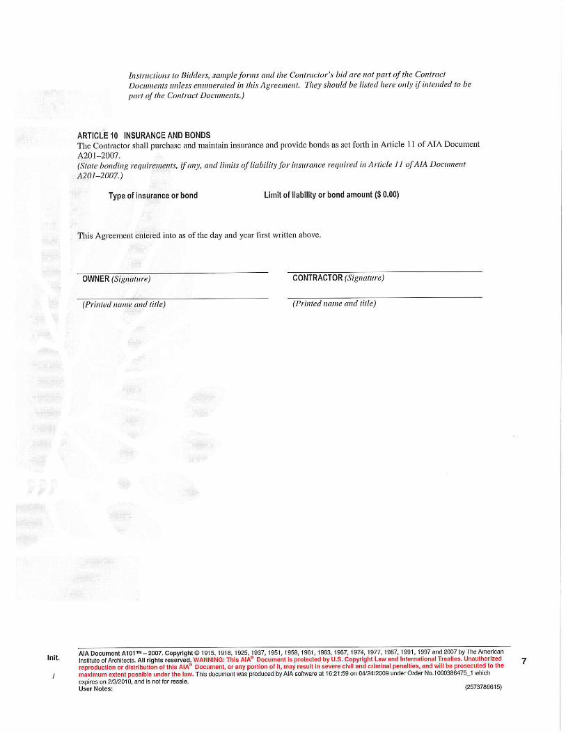
A. American Institute of Architects, AIA Document A101, “Standard Form of Agreement Between Owner and Contractor where the Basis of Payment is a Stipulated Sum,” 2007 Edition, shall be the basis of agreement for this Project.
B. Example blank form copy of AIA Document A101 follows.
1.2 AGREEMENT PREPARATION AND EXECUTION PROCEDURE
A. All signatures shall be in Blue Ink to clearly identify agreement as an original signed document.
B. Upon award of contract by the Owner, the Architect will prepare the Agreement forms and
transmit three (3) copies to the Contractor for attachment of Bond Forms Insurance Certificates, Affidavits and Contractor signature.
C. Upon signature by Contractor, Contractor shall transmit the three (3) copies of the
Agreement Package to the Architect for review. The Agreement Package shall include three (3) copies the following: 1. Signed Agreement form, indicating project completion date of July 01, 2013. 2. Executed, signed and sealed Performance Bond form. 3. Executed, signed and sealed Payment Bond form. 4. Executed, signed and sealed Defect Bond form. 5. Executed, signed and sealed Insurance Certificate on ACORD form 25-S. 6. Executed, signed and sealed AIA Document G715 Supplemental Attachment (for
ACCORD certificate of insurance 25-S). 7. Executed, signed and sealed Oklahoma Workmen’s Compensation Insurance
Certificate (if not included in ACORD form 25-S). 8. Executed, signed and notarized Contract Affidavit. 9. Executed, signed and notarized Tobacco-Free Affidavit. 10. Executed, signed and notarized Drug-Free Affidavit.
D. Upon receipt of the Agreement Package from the Contractor, the Architect will review the
package and verify that all requirements are met and package is prepared properly.
E. If Architect determines that Agreement Package is prepared properly, Architect will transmit Agreement Package to Owner for signature.
F. Owner will sign Agreement, keep one (1) copy and return two copies to Architect.
G. Architect will transmit one (1) executed copy of Agreement Package to Contractor.
H. Upon receipt of executed Agreement Package and authorization from Owner, Architect will
issue Notice to Proceed to Contractor for Owner.

00 5213 - 2 Anadarko Mission Elementary School Restroom Renovation Anadarko, OK Project No. N12024MSTR 04/08 AGREEMENT-STIPULATED SUM
PART 2 PRODUCTS Not Used. PART 3 EXECUTION Not Used. END OF DOCUMENT


00 5313 - 1 Anadarko Mission Elementary School Restroom Renovation Anadarko, OK Project No. N12024MSTR 04/08 CONTRACT AFFIDAVIT
DOCUMENT 00 5313 BWA N12024 CONTRACT AFFIDAVIT STATE OF__________________)
)ss. COUNTY OF_________________) _________________________________of lawful age, being of first duly sworn, on oath says that
_______________________is the agent authorized by Contractor to submit the attached Contract to the
Board of Education, in the District as stated below, and the County as stated below, in the State of
Oklahoma. Affiant further states that Contractor has not paid, given or donated or agreed to pay, give or
donate to any officer or employee to the Board of Education, in the District stated below, in the County
stated below, in the State of Oklahoma, any money or other thing of value, either directly or indirectly, in
the procuring of the Contract.
Project Name : in the District Number in the County of in the State of Oklahoma. _________________________________________ Subscribed and sworn to before me this _________day of ________________, 20___. ___________________________________ Notary Public ____________________________________ My Commission Expires:
END OF DOCUMENT

00 5315 - 1 Anadarko Mission Elementary School Restroom Renovation Anadarko, OK Project No. N12024MSTR 04/08 TOBACCO-FREE AFFIDAVIT
DOCUMENT 00 5315 BWA N12024 TOBACCO-FREE AFFIDAVIT STATE OF__________________)
)ss. COUNTY OF_________________) I _________________________________of lawful age, being of first duly sworn, on oath says that
_______________________is the agent authorized by Contractor to submit the attached Tobacco-Free
Affidavit to the Board of Education, in the District as stated below, and the County as stated below, in the
State of Oklahoma. Affiant further states the following:
1. No employee working on premises under the authority of the Contractor will be permitted to use tobacco products in school facilities and on school property. The Contractor, sub-contractors and suppliers, their agents or employees, and any other persons performing any Work on behalf of the Contractor, will not use tobacco products on school property.
2. Contractor agrees to prominently display a Notice stating that school property is a tobacco-free site.
Project Name : in the District Number in the County of in the State of Oklahoma. _________________________________________ Subscribed and sworn to before me this _________day of ________________, 20___. ___________________________________ Notary Public ____________________________________ My Commission Expires:
END OF DOCUMENT
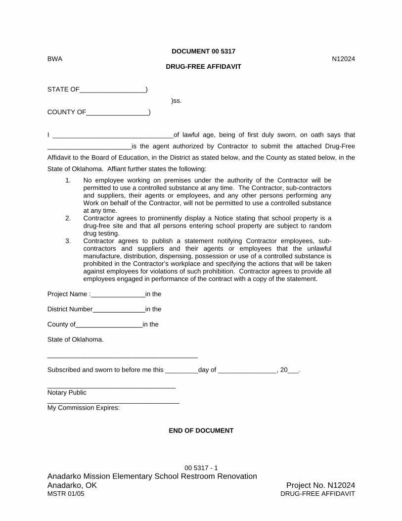
00 5317 - 1 Anadarko Mission Elementary School Restroom Renovation Anadarko, OK Project No. N12024MSTR 01/05 DRUG-FREE AFFIDAVIT
DOCUMENT 00 5317 BWA N12024 DRUG-FREE AFFIDAVIT STATE OF__________________)
)ss.
COUNTY OF_________________)
I _________________________________of lawful age, being of first duly sworn, on oath says that
_______________________is the agent authorized by Contractor to submit the attached Drug-Free
Affidavit to the Board of Education, in the District as stated below, and the County as stated below, in the
State of Oklahoma. Affiant further states the following:
1. No employee working on premises under the authority of the Contractor will be permitted to use a controlled substance at any time. The Contractor, sub-contractors and suppliers, their agents or employees, and any other persons performing any Work on behalf of the Contractor, will not be permitted to use a controlled substance at any time.
2. Contractor agrees to prominently display a Notice stating that school property is a drug-free site and that all persons entering school property are subject to random drug testing.
3. Contractor agrees to publish a statement notifying Contractor employees, sub-contractors and suppliers and their agents or employees that the unlawful manufacture, distribution, dispensing, possession or use of a controlled substance is prohibited in the Contractor’s workplace and specifying the actions that will be taken against employees for violations of such prohibition. Contractor agrees to provide all employees engaged in performance of the contract with a copy of the statement.
Project Name : in the District Number in the County of in the State of Oklahoma. _________________________________________ Subscribed and sworn to before me this _________day of ________________, 20___. ___________________________________ Notary Public ____________________________________ My Commission Expires:
END OF DOCUMENT

00 6100 - 1 Anadarko Mission Elementary School Restroom Renovation Anadarko, OK Project No. N12024MSTR 09/08 BONDS
DOCUMENT 00 6100 BWA N12024 BONDS PART 1 GENERAL 1.1 SUMMARY
A. Document Includes: 1. Performance Bond. 2. Labor and material payment bond (statutory bond). 3. Defect bond. 4. Irrevocable letter of credit. 5. Defect Bond Form.
B. Related Documents:
1. The Contract Documents, as defined in Document 00 7213 - General Conditions and modifications thereto, apply to the Work of this Section. Additional requirements and information necessary to complete the Work of this Section may be found in other documents.
2. Document 00 7213 - General Conditions: Article 11, Paragraph 11.4, Performance Bond and Payment Bond.
1.2 SUBMITTALS
A. Non-Specified Forms: If Surety Company proposes to use a bond form other than form specified, Surety shall submit proposed form to Owner, through Contractor, for Owner review and approval before preparation of bonds for this Project. Proposed form shall contain the same requirements and responsibilities as specified forms.
B. Submittals: Submit the following as part of the Agreement Package.
1. Bonds: Submit fully executed original copies of each bond attached to each copy of Agreement between Owner and Contractor.
2. Power of Attorney. Attach an original copy of Power of Attorney to each copy of each bond.
3. Bond Rate Schedule: Attach surety’s bond rate schedule applicable for Subcontractor indicating the percentage fee used to compute Project bond amounts and for computing of bond amounts for increases in Contract Sum for Change Orders.
1.3 BOND REQUIREMENTS
A. Bonds are required for Projects with contract amount exceeding $50,000. B. Attorney-In-Fact who executes required bonds on behalf of surety shall affix a certified and
current Power of Attorney to each bond. 1.4 PERFORMANCE BOND
A. Amount: Equal to 100 percent of Contract Sum.

00 6100 - 2 Anadarko Mission Elementary School Restroom Renovation Anadarko, OK Project No. N12024MSTR 09/08 BONDS
B. Form: AIA Document A312 “Performance Bond,” 1984 Edition or other forms acceptable to Owner.
1.5 LABOR AND MATERIAL PAYMENT BOND (Statutory Bond)
A. Amount: Equal to 100 percent of Contract Sum.
B. Form: AIA Document A312 “Payment Bond,” 1984 Edition or other forms acceptable to Owner.
1.6 DEFECT BOND
A. Amount: Equal to 100 percent of Contract Sum.
B. Form: Form of this bond is attached to this Section. 1.7 IRREVOCABLE LETTER OF CREDIT
A. An Irrevocable Letter of Credit may be used if construction cost of the Project is under $100,000 in lieu of specified bonds indicated above.
PART 2 PRODUCTS Not Used. PART 3 EXECUTION Not Used. END OF DOCUMENT

00 6100 - 3 Anadarko Mission Elementary School Restroom Renovation Anadarko, OK Project No. N12024MSTR 09/08 BONDS
DEFECT BOND KNOW BY ALL MEN BY THESE PRESENTS: That __________________________________________________________ as Principal, and
_____________________________________________ a corporation organized under the laws of the
State of _______, and authorized to transact business in the State in which the Work (Project) is to be
performed, as Surety, are held and firmly bound unto The Owner in the sum of
____________________________________ Dollars ($________________________) in lawful money of
the United States of America, said sum being equal to One Hundred Percent (100%) of the Contract
Sum, for the payment of which, well and truly to be made, we bind ourselves and each of us, our heirs,
executors, administrators, trustees, successors, and assigns, jointly and severally, firmly by these
presents.
This condition of this obligation is such that: WHEREAS, said Principal entered into a written Contract with the Owner, dated
_______________________________________________________________, 20_____, for
___________________________________________________________________________________
___________________________________________________________________________________
___________________________________________________________________________________
___________________________________________________________________________________
___________________________________________________________________________________
_____all in compliance with the Contract Documents therefore, made a part of said Contract and on file in
the office of the Owner.
NOW, THEREFORE, if said Principal shall pay or cause to be paid to the Owner all damage, loss and expense which may result by reason of defective materials and/or workmanship in connection with said Work, occurring within a period of one (1) year from and after the date of Substantial Completion of said project; then this obligation shall be null and void, otherwise to be and remain in full force and effect. It is further expressly agreed and understood by the parties hereto that no changes or alterations in said Contract and no deviations from the plan or mode of procedure herein fixed shall have the effect or releasing the sureties, or any of them from the obligations of this Bond. IN WITNESS WHEREOF, the said Principal has caused these presents to be executed in its name and its corporate seal to be hereunto affixed by its duly authorized officers, and the said Surety has caused these presents to be executed in its name and its corporate seal to be hereunto affixed by its attorney-in-fact, duly authorized so to do, the day and year set forth below. DATED this ___________________ day of _________________________, 20 ___

00 6100 - 4 Anadarko Mission Elementary School Restroom Renovation Anadarko, OK Project No. N12024MSTR 09/08 BONDS
PRINCIPAL: _____________________________________ By: __________________________________ Title ATTEST: ____________________________________ SURETY: ______________________________________ By:____________________________________ Attorney-In-Fact (Type) Name:____________________________ Address:________________________________ City: _____________________ State: _______ Telephone: _________________
END OF DEFECT BOND
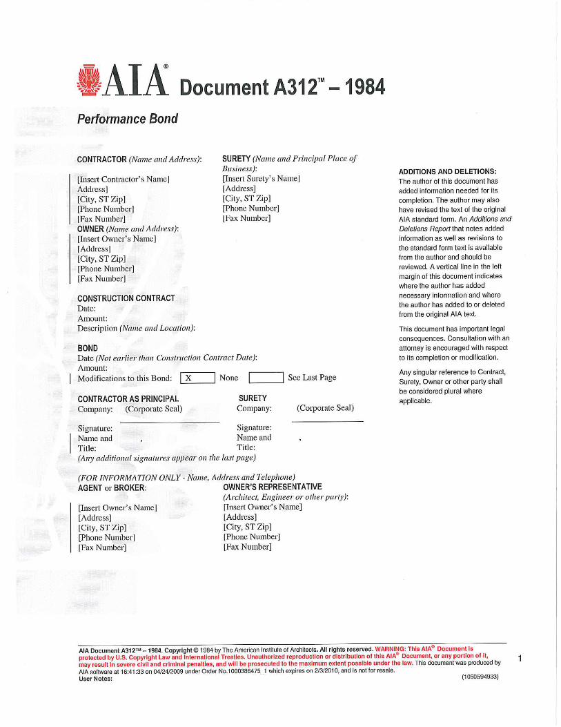


00 7213 - 1 Anadarko Mission Elementary School Restroom Renovation Anadarko, OK Project No. N12024MSTR 0609 GENERAL CONDITIONS
DOCUMENT 00 7213 BWA N12024 GENERAL CONDITIONS PART 1 GENERAL
1.1 GENERAL CONDITIONS
A. American Institute of Architects, AIA Document A201 “General Conditions of the Contract for Construction,” 2007 Edition, shall be General Conditions for this Project. 1. Reader is encouraged to reference the accompanying “Additions and Deletions
Report” for modifications made to original Document. B. Copy of AIA Document A201 including modifications thereto follows.
1. Within primary body of Document, language added to the standard Document is indicated in bold black test.
PART 2 PRODUCTS Not Used. PART 3 EXECUTION Not Used.
END OF DOCUMENT


00 7316 - 1 Anadarko Mission Elementary School Restroom Renovation Anadarko, OK Project No. N12024MSTR 0410 INSURANCE REQUIREMENTS
DOCUMENT 00 7316 BWA N12024 INSURANCE REQUIREMENTS PART 1 GENERAL 1.1 SUMMARY
A. Document Includes: 1. Workers compensation insurance. 2. Preparation of Certificates of Insurance. 3. Contractor’s general liability insurance. 4. Owner’s liability insurance. 5. Property insurance. 6. Notice of cancellation. 7. Certificate of Insurance issued by Insurer or Insurer’s Agency approved by the State
of Oklahoma Insurance Department.
B. Related Documents and Sections: 1. The Contract Documents, as defined in Document 00 7213 - General Conditions and
modifications thereto, apply to the Work of this Section. Additional requirements and information necessary to complete the Work of this Section may be found in other documents.
2. Document 00 5213 - Agreement-Stipulated Sum: Certificates of insurance as part of Agreement Package.
3. Section 0 1 7700 - Closeout Procedures: Contract Closeout Package. 1.2 DEFINITIONS
A. Broad Form Property Damage: An endorsement to a General Liability policy that deletes the exclusion referring to property in the care, custody, or control of the insured and replaces it with a less restrictive exclusion.
B. Builder's All-Risk (Builder's Risk) Property Insurance: Indemnifies for loss of or damage to
a building under construction. Insurance is normally written for a specified amount on the building and applies only in the course of construction.
C. Independent Contractor's Protective (Owners and Contractors Protective Liability
Insurance): Protects an insured against losses caused by the negligence of a contractor or subcontractor that Contractor hires.
D. Premises and Operations Liability Insurance: Liability coverage for exposures arising out
of an insured's premises and business operations.
E. Products and Completed Operations Insurance: Liability coverage for an insured against claims arising out of products sold, manufactured, handled, or distributed, or operations which are complete. Claims are covered only after a product has been sold and possession relinquished, or operations have been completed or abandoned by the named insured.
F. Waivers of Subrogation: Named insured's intentional relinquishing of any right to recover
damages from another party who may be responsible.

00 7316 - 2 Anadarko Mission Elementary School Restroom Renovation Anadarko, OK Project No. N12024MSTR 0410 INSURANCE REQUIREMENTS
1.3 SUBMITTALS
A. Contractor Review of Certificates: Contractor shall review each Certificate of Insurance to verify that Contractor Insurance Provider has correctly provided all specified insurance coverage and the correct coverage amounts before submitting with the Agreement Package. If Contractor finds that Insurance Provider has submitted incomplete or incorrect Certificates of Insurance, Contractor shall immediately contact Insurance Provider, advise what items are incomplete or incorrect, and have Insurance Provider immediately issue corrected Certificates of Insurance.
B. Certificate Submittal: Submit three (3) fully executed Certificates of Insurance ACORD
form 25-S, State Workers Compensation Insurance Certificate and Certificate of Insurance attached to the Agreement between Owner and Contractor as part of the Agreement Package as specified in Document 00 5213 - Agreement-Stipulated Sum. 1. If Contractor Worker's Compensation Insurance is not included on ACORD 25-S
Certificate of Insurance, Contractor shall provide a separate State Workers Compensation Insurance Certificate from a Workers Compensation Insurance company lawfully authorized to provide Workers Compensation Insurance in the State of Oklahoma.
2. Worker's Compensation Insurance Certificate shall indicate that minimum of 30 days written Notification of Cancellation shall be provided to Owner. Ten (10) days written Notification of Cancellation not acceptable.
C. Certificate Form: Submit on form indicated in Document 00 7213 - General Conditions,
Subparagraph 11.1.3. 1. Attach Certificate of Insurance to each certificate.
D. Filing of Certified Policy Copies: Contractor shall file with the Owner, through the Architect,
a certified copy of each policy that includes insurance coverages required by Document 00 7213 - General Conditions, Article 11.4 no later than the Date of Notice to Proceed.
E. Final Completion Submittal: Submit three (3) fully executed Certificates of Insurance on
ACORD 25-S form with attached Certificate of Insurance to each certificate. Indicate Products and Completed Operations Insurance coverage for one (1) year from Date of Final Completion as part of the Contract Closeout Package specified in Section 01 7700 - Closeout Procedures.
1.4 INCOMPLETE OR INCORRECT CERTIFICATES OF INSURANCE
A. Incomplete Submittals: Processing will stop for Certificates of Insurance received by Architect that do not include all required items. Architect will contact Contractor and advise Contractor of missing items. Contractor is responsible for sending Architect items missing from the Certificates of Insurance. Processing on Certificates of Insurance related items will not start until Certificates of Insurance are complete.
B. Incorrect Submittals: Certificates of Insurance that are incorrectly submitted or have
incorrect coverage will be returned to Contractor for correction.
C. Contractor is responsible for Certificates of Insurance related items being stopped due to submittal of incomplete or incorrect Certificates of Insurance.

00 7316 - 3 Anadarko Mission Elementary School Restroom Renovation Anadarko, OK Project No. N12024MSTR 0410 INSURANCE REQUIREMENTS
1.5 PREPARATION OF CERTIFICATES OF INSURANCE
A. Upon receipt of Notice of Award of Contract, Contractor shall contact insurance provider to provide coverage as specified in this Document. Contractor shall send copies of the following to insurance provider so that insurance provider will know exactly what coverage is required. 1. General Conditions Article 11 - Insurance and Bond 2. Document 00 7316- Insurance Requirements. 3. Three (3) copies of Certificate of Insurance issued by Insurer or Insurer’s Agency
approved by the State of Oklahoma Insurance Department.
B. Certificate Holder Box: 1. List the Owner as the Certificate Holder on ACORD 25-S form. 2. List the Owner as the Certificate Holder on separate Worker Compensation
Insurance certificate form. 3. Architect is not the Certificate Holder.
C. Description of Operations Box: Include the following in this box on ACORD 25-S form.
1. List the Project Title and Project Address. 2. Include Waiver of Subrogation text as follows "Waiver of Subrogation is provided in
favor of the Architect, its consultants, separate contractors and the Owner, its sub-subcontractors, agents and employees."
3. Any other descriptions or endorsements.
D. Coverages Box: Clearly indicate specified coverages on ACORD 25-S form by separately listing each coverage specified to allow Owner and Architect to quickly verify that all coverages and coverage amounts are included. 1. General Liability Box: List the following as a line item indicating coverage is included.
a. Premises-Operations b. Independent Contractor's Protective. c. Products and Completed Operations coverage for one (1) year from date of
Final Payment. d. Broad Form Property Damage. e. Indicate coverage amounts in corresponding limits box for each item exactly as
indicated in this Section: 1) Bodily Injury. 2) Property Damage. 3) Property Damage Liability. 4) Contractual Liability. 5) Personal Injury. 6) General Liability.
2. Automobile Liability Box: List the following as a line item indicating coverage is included and coverage amounts in corresponding limits box for each item exactly as indicated in this Section. a. Bodily Injury Each Person. b. Bodily Injury Each Occurrence. c. Property Damage Each Occurrence.
3. Workers Compensation and Employee Liability Box: List the following as a line item indicating coverage is included and coverage amounts in corresponding limits box for each item exactly as indicated in this Section or a separate certificate from a separate company providing Workers Compensation Insurance. a. Applicable Federal. b. Applicable State.

00 7316 - 4 Anadarko Mission Elementary School Restroom Renovation Anadarko, OK Project No. N12024MSTR 0410 INSURANCE REQUIREMENTS
c. Employer's Liability. 4. Other Box: List the following as a line item indicating coverage is included and
coverage amounts in corresponding limits box. a. Builders All-Risk Insurance.
E. Certificate of Insurance issued by Insurer or Insurer’s Agency approved by the State of
Oklahoma Insurance Department defining and defining the following: 1. Certification shall include the following under General Liability:
a. Include General Aggregate for Project. b. Coverages:
1) Premises Operations. 2) Explosion, Collapse, and Underground Hazards 3) Personal Injury Coverage 4) Products Coverage 5) Completed Operations 6) Contractual Coverage for the Insured’s obligations
c. Claims-Made Basis is not applicable. 2. Worker's Compensation is not applicable. 3. Final Payment Information:
a. This Certificate shall not be furnished in connection with Contractor’s request for final payment.
b. Completed Operations coverage for Project shall continue for the balance of the policy period.
4. Termination Provisions: Each policy listed on Certification shall be endorsed to provide holder with 30 day notice of cancellation or termination.
5. Other Provisions: Insurance Provider may list any other insurance provisions applicable to Project. Coverages not listed in the General Liability heading can be listed under this heading.
1.6 WORKERS COMPENSATION INSURANCE
A. Refer to Document 00 7213 - General Conditions: Contractor shall purchase from and maintain in a company lawfully authorized to do business in jurisdiction in which the Project is located Workers Compensation Insurance with specified coverage amounts.
B. Coverage Amounts:
1. Applicable Federal: Statutory. 2. Applicable State: Statutory. 3. Employer’s Liability: $500,000.
1.7 CONTRACTOR’S GENERAL LIABILITY INSURANCE
A. Refer to Document 00 7213 - General Conditions:. Contractor shall purchase from and maintain in a company lawfully authorized to do business in jurisdiction in which the Project is located General Liability Insurance with specified coverages and coverage amounts.
B. Coverage Includes:
1. Premises-Operations. 2. Independent Contractor’s Protective. 3. Products and Completed Operations.
a. Maintain coverage for one (1) year after final payment (extends beyond Contractor warranty period).
4. Broad Form Property Damage.

00 7316 - 5 Anadarko Mission Elementary School Restroom Renovation Anadarko, OK Project No. N12024MSTR 0410 INSURANCE REQUIREMENTS
a. Blasting or explosion. b. Collapse of structural injury to any building or structure due to excavating,
drilling, pile driving, coffer-dam or caisson work. c. Moving, shoring, underpinning, razing, or demolition of any building or
structure. d. Removal or rebuilding of structural support of items indicated above while such
operations are being performed by the Contractor.
C. Coverage Amounts: 1. Bodily Injury:
a. Each Occurrence: $500,000. b. Aggregate: $1,000,000.
2. Property Damage: a. Each Occurrence: $500,000. b. Aggregate: $1,000,000.
3. Property Damage Liability, include for the following hazards: a. X – Explosion. b. C – Collapse. c. U – Underground.
4. Contractual Liability (Hold Harmless Coverage): a. Bodily Injury:
1) Each Occurrence: $1,000,000. b. Property Damage:
1) Each Occurrence: $500,000. 2) Aggregate: $1,000,000.
5. Personal Injury (with Employment Exclusion deleted, if applicable): a. Aggregate: $1,000,000.
6. General Liability: a. If policy includes a General Aggregate:
1) Such General Aggregate shall be not less than $1,000,000. 2) Policy shall be endorsed to have General Aggregate apply to this project
only. 7. Automobile Liability:
a. Bodily Injury Each Person: $1,000,000. b. Bodily Injury Each Occurrence: (CSL) or its equivalent c. Property Damage Each Occurrence: $500,000
1.8 OWNER’S LIABILITY INSURANCE
A. Refer to Document 00 7213 - General Conditions: Owner shall be responsible for purchasing and maintaining Owner's usual liability insurance.
1.9 PROPERTY INSURANCE - BUILDERS RISK
A. Refer to Document 00 7213 - General Conditions: Contractor shall purchase Property Insurance from and maintain in a company lawfully authorized to do business in jurisdiction where Project is located.
B. The Contractor shall purchase with the following modifications:
1. Upon all new Work at the site to the full insurable value thereof. This insurance shall include the interests of the Owner, the Contractor, Subcontractors and Sub-subcontractors in the Work and shall insure against the perils of fire, water and extended coverage and "ALL RISK" per General Conditions.

00 7316 - 6 Anadarko Mission Elementary School Restroom Renovation Anadarko, OK Project No. N12024MSTR 0410 INSURANCE REQUIREMENTS
a. Coverage includes physical loss or damage including, without duplication of coverage, theft, vandalism, malicious mischief, collapse, earthquake, flood, windstorm, false work, testing and startup, temporary buildings, and debris removal including demolition occasioned by enforcement of any applicable legal requirements, and shall cover reasonable compensation for Architect's and Contractor's services and expenses required as a result of such insured loss.
b. Insurance shall cover portions of Work stored off-site and also portions of Work in transit.
2. Insurance carried shall be in the amount of 100 percent of the contract cost plus 3 percent to cover additional cost (fees) incurred by the Architect.
C. Waivers of Subrogation: Refer to Document 00 7213 - General Conditions.
1.11 NOTICE OF CANCELLATION
A. All Certificates of Insurance, which are required by this Section shall be furnished by Contractor, shall include a minimum of 30 days Notice of Cancellation to be provided to the Owner clause.
PART 2 PRODUCTS Not Used. PART 3 EXECUTION Not Used. END OF DOCUMENT


00 7375 - 1 Anadarko Mission Elementary School Restroom Renovation Anadarko, OK Project No. N12024MSTR 01/05 FELONY COMPLIANCE
DOCUMENT 00 7375 BWA N12024 FELONY COMPLIANCE PART 1 GENERAL 1.1 SUMMARY
A. Section Includes: 1. State Law criminal background requirements for all persons working on school
premises. 2. Documentation of compliance submittals to Owner. 3. Felony and Sex Offenders Affidavit, located at end of Document (for use if School
does not have a prepared form).
B. Related Documents: 1. The Contract Documents, as defined in Document 00 7213 - General Conditions and
modifications thereto, apply to the Work of this Section. Additional requirements and information necessary to complete the Work of this Section may be found in other documents.
1.2 SUBMITTALS
A. Upon receipt of Notice of Award of Contract, contact School District Superintendent’s Office
to obtain copies of forms for certification of compliance with specified state law and School requirements and procedures for compliance with specified state law. 1. If School does not have a form, use form at end of this Document.
B. Certify to School District that all Contractor personnel, all subcontractor personnel and all
personnel of suppliers or vendors entering school premises comply with specified state law regarding criminal background.
C. Submit completed certification of compliance documentation to School Superintendent
before starting Work on school premises. 1.3 APPLICABLE OKLAHOMA STATE STATUTE
A. Effective July 1, 1998 all persons (company, partnership, contractor, sub-contractor, service provider, vendor) shall be in compliance with Chapter 411, Senate Bill No. 1394.
B. It is unlawful for any person registered pursuant to the Sex Offenders Registration Act to
work with or provide services to children or to work on school premises, or for any person or business who offers or provides services to children or contracts for work to be performed on school premises to knowingly and willfully allow any employee to work with children or to work on school premises who is registered pursuant to the Sex Offenders Registration Act.
C. Upon conviction for any violation of the provisions of this subsection, the violator shall be
guilty of a misdemeanor punishable by a fine not to exceed One Thousand Dollars ($1,000.00). In addition, the violator may be liable for civil damages.
END OF DOCUMENT

00 7375 - 2 Anadarko Mission Elementary School Restroom Renovation Anadarko, OK Project No. N12024MSTR 01/05 FELONY COMPLIANCE
FELONY AND SEX OFFENDERS AFFIDAVIT Contractor
STATE OF OKLAHOMA )
)ss. COUNTY OF__________________ ) The undersigned, under penalties of perjury, certifies to the _______________ Public Schools ISD __IO___ (“District”) as follows: 1. The undersigned is the duly authorized representative of a business (“entity”) having a contract
with the District, to perform Work at __________________________________ on a full time basis, which work would not otherwise be performed by District employees.
2. The undersigned hereby certifies that the undersigned will not allow any employee of the
undersigned or of the entity, or of any subcontractor, to perform Work on District premises on a full-time basis that would otherwise be performed by District employees if such employee is convicted in the State, United States, or another state of any felony offence.
3. No employee of the undersigned, or entity, who performs any Work on District property is
currently registered under the Oklahoma Sex Offenders Registration Act. 4. The undersigned, or entity: ______ has or ______ has not conducted a felony record search of employees who would be assigned to work on a part-time or
full-time basis on District property. 5. This Affidavit is intended to comply with Senate Bill 588 of the 1999 Oklahoma Legislative
Session. 6. It is our understanding that failure to comply with this affidavit will result in immediate cancellation
of the contract with the District. EXECUTED AND DELIVERED this _________________ day of ______________, 20___ . ________________________________________ (company name) BY: ____________________________________ (authorized signature) Subscribed and sworn to before me this ____________day of _____________, 20___. ________________________________________________ Affix Seal Notary Public _______________________________________________ My Commission expires:

00 7375 - 3 Anadarko Mission Elementary School Restroom Renovation Anadarko, OK Project No. N12024MSTR 01/05 FELONY COMPLIANCE
FELONY AND SEX OFFENDERS AFFIDAVIT Subcontractors
STATE OF OKLAHOMA )
)ss. COUNTY OF__________________ ) The undersigned, under penalties of perjury, certifies to the _______________ Public Schools ISD __IO___ (“District”) as follows: 1. The undersigned is the duly authorized representative of a business (“entity”) having a contract
with ___________________________ , the General Contractor who has a contract with the District, to perform Work at __________________________________ on a full time basis, which Work would not otherwise be performed by District employees.
2. The undersigned hereby certifies that the undersigned will not allow any employee of the undersigned or of the entity, or of any subcontractor, to perform Work on District premises on a full-time basis that would otherwise be performed by District employees if such employee is convicted in the State, United States, or another state of any felony offence.
3. No employee of the undersigned, or entity, who performs any Work on District property is currently registered under the Oklahoma Sex Offenders Registration Act.
4. The undersigned, or entity: ______ has or ______ has not conducted a felony record search of employees who would be assigned to work on a part-time or
full-time basis on District property. 5. This Affidavit is intended to comply with Senate Bill 588 of the 1999 Oklahoma Legislative
Session. 6. It is our understanding that failure to comply with this affidavit will result in immediate cancellation
of the contract with _______________________________________ . EXECUTED AND DELIVERED this _________________ day of ______________, 20___ . ________________________________________ (company name) BY: ____________________________________ (authorized signature) Subscribed and sworn to before me this ____________day of _____________, 20___. ________________________________________________ Affix Seal Notary Public _______________________________________________ My Commission expires:
END OF NOTIFICATION

00 7390 - 1 Anadarko Mission Elementary School Restroom Renovation Anadarko, OK Project No. N12024 MSTR 04/08 SALES TAX EXEMPTION/DESIGNATION OF PURCHASING AGENT
DOCUMENT 00 7390 BWA MSTR 04/08 SALES TAX EXEMPTION / DESIGNATION OF PURCHASING AGENT PART 1 GENERAL 1.1 SUMMARY
A. Section Includes: 1. Sales tax exemption notification. 2. Contractor procedure for obtaining sales tax exemption. 3. Procedure for purchases. 4. Sales Tax Agency Agreement located at end of Document.
B. Related Documents:
1. The Contract Documents, as defined in Document 00 7213 - General Conditions and modifications thereto, apply to the Work of this Section. Additional requirements and information necessary to complete the Work of this Section may be found in other documents.
1.2 SALES TAX EXEMPTION NOTIFICATION (68 OS 1356)
A. State and Municipal sales tax shall not be included in Bids submitted for tangible personal property required for this Project in accordance with 68 OS 1356 of the Oklahoma Statutes that reads in summary as follows: 1. In order to qualify for any exemption authorized by Section 1356 of Title 60 of the
Oklahoma Statutes, at the time of sale, the person to whom the sale is made may be required to furnish the vendor proof of eligibility for such exemption.
2. All vendors shall honor the proof of eligibility for sales tax exemption as authorized by this section and sales to a person providing such proof shall be exempt from the tax levied.
3. There are hereby specifically exempted from the tax levied: a. Sale of tangible personal property to any public school district or to any person
with whom the public school district has duly entered into a public contract. Any person making purchases on behalf of such subdivision or agency of this state shall certify, in writing, on the copy of the invoice or sales ticket to be retained by the vendor that the purchases are made for and on behalf of such public school district and set out the name of such public school district.
b. Sales of tangible personal property to a public school district pursuant to a lease-purchase agreement executed between the vendor and public school district.
B. All contracts with Subcontractors shall include the following provision:
“All tangible personal property and materials are being purchased by Contractor or Subcontractor for and on behalf of the School District and title to the materials and property shall pass directly from the vendor to the School District.”
C. All tangible personal property sold or leased direct to School District by vendor is exempt
from State and Municipal sales tax.

00 7390 - 2 Anadarko Mission Elementary School Restroom Renovation Anadarko, OK Project No. N12024 MSTR 04/08 SALES TAX EXEMPTION/DESIGNATION OF PURCHASING AGENT
D. Contractor shall be responsible for care and safekeeping of all tangible personal property delivered to Project Site, even though title to property has passed to School District. This shall include responsibility to properly secure tangible personal property, to replace any tangible personal property lost or stolen or which, through any means disappears from the Project Site, and further the obligation to pay any deductible required to be paid under any insurance policy that may cover the loss if such insurance is in effect, and the responsibility to meet any requirements imposed by insurance company carrying insurance on property insofar as the care, safekeeping and protection of the property is concerned.
E. The Contractor, upon award of Contract, shall prepare the attached Sales Tax Agency
Agreement form, or other agreement form for this purpose provided by the School District, and contact the School District to obtain signatures and execute the Agreement. The attached Sales Tax Agency Agreement authorizes Contractor to be Purchasing Agent for the School District on the Project.
1.3 CONTRACTOR PROCEDURE FOR OBTAINING SALES TAX EXEMPTION
A. Obtaining execution of the Sales Tax Agency Agreement at the start of Project is entirely the responsibility of the Contractor. Contractor shall make all arrangements with School District for executing the Sales Tax Agency Agreement.
B. Contractor shall obtain original signed copies of the executed Sales Tax Agency
Agreement in the number necessary for identifying Subcontractor and Sub-subcontractor that will be eligible for Sales Tax Exemption for this Project.
C. Contractor may bring Sales Tax Agency Agreement to the Pre-Construction Meeting to
obtain School District Signature and execute Agreement. Contractor shall contact School District and make prior arrangements with School District. Architect does not prepare forms or obtain signatures for Contractor.
D. After execution of the Sales Tax Agency Agreement, Contractor forwards executed
Agreement along with cover letter on Contractor Letterhead, indicating that Subcontractor or Sub-subcontractor are authorized by Contractor to purchase material and equipment for the Project as a part of their subcontract, to the appropriate Subcontractors and Sub-subcontractors, as necessary, for their use.
1.4 PROCEDURE FOR PURCHASES
A. Contractor, Subcontractor or Sub-subcontractor identifies themselves to vendor Contractor, Subcontractor, or Sub-Subcontractor is making purchase of tangible personal property from as a Designated Purchasing Agent pursuant to a contract for construction of this Project with the School District.
B. Contractor, Subcontractor or Sub-Subcontractor provides a copy of an original signed and
executed Sales Tax Agency Agreement to vendor upon request.
C. Contractor, Subcontractor or Sub-subcontractor certifies, in writing, on copy of invoice or sales ticket retained by vendor that purchases are made for and on behalf of School District as specified in the executed Sales Tax Agency Agreement.
D. In order for any individual invoice from vendor to qualify for tax exemption, it shall reflect
upon it's face, the following:

00 7390 - 3 Anadarko Mission Elementary School Restroom Renovation Anadarko, OK Project No. N12024 MSTR 04/08 SALES TAX EXEMPTION/DESIGNATION OF PURCHASING AGENT
1. The purchase order was submitted by Contractor as agent for School District, not by Contractor individually.
2. The Project Site where material and equipment was delivered and that material and equipment was, in fact, delivered to Project Site belonging to School District.
3. That from a description of building material or equipment same as appears on purchase order, it is clearly evident that such material and equipment became a part of the construction of the Project.
4. Title to such material and equipment passed from vendor directly to School District. 1.5 PREPARATION, MAINTENANCE AND SUBMITTAL OF RECORD OF PURCHASE ORDERS
A. Contractor, each Subcontractor and each Sub-subcontractor shall maintain a record for all purchase orders issued under this tax exemption and be prepared to provide a current accurate copy of record to School District upon request at any time.
B. The purpose of maintaining and submitting a Purchase Order Record is for School District
records to monitor Contractor tax exempt expenditures and to assure expenditures were in accordance with Oklahoma Statute 68 OS 1356 should a question arise.
C. Each Subcontractor and each Sub-subcontractor shall submit a complete accurate record
for each purchase orders issued under this tax exemption by Subcontractor and Sub-subcontractor to Contractor at a date designated by Contractor before Substantial Completion. Sub-subcontractors shall submit their purchase order record to Contractor through their respective Sub-subcontractor.
D. Contractor, Subcontractor and Sub-subcontractor shall maintain copies of all purchase
orders and their corresponding vendor invoices for the Project and be prepared to provide copies of the purchase orders and vendor invoices upon request of the Owner.
E. Contractor shall submit complete accurate Purchase Order Record as a Closeout
Submittal. Refer to Section 01 7700 - Closeout Procedures and Section 01 7800 - Closeout Submittals.
1.6 DESIGNATION OF PURCHASING AGENT FOR OWNER
A. Sales Tax Agency Agreement form follows. Contractor and Owner shall execute this Agreement at the start of the Project.
B. Text of Sales Tax Agency Agreement is suggested by Oklahoma State Department of
Education in their 2004 publication "The ABC's of Building a School." Individual School Districts may choose to use different agreement text or a different agreement form altogether. Verify with School District.
C. All signatures on Sales Tax Agency Agreement shall be in Blue Ink to clearly identify
Agreement as an original signed document.
END OF DOCUMENT

00 7390 - 4 Anadarko Mission Elementary School Restroom Renovation Anadarko, OK Project No. N12024 MSTR 04/08 SALES TAX EXEMPTION/DESIGNATION OF PURCHASING AGENT
SALES TAX AGENCY AGREEMENT This is an Agency Agreement made and entered into as of the __________ day of _________, 20__ ,
between __________________________ SCHOOL DISTRICT NUMBER _____ of
___________________ COUNTY, OKLAHOMA, a political subdivision of the State of Oklahoma
(hereinafter referred to as "Owner"), and ____________________________ (hereinafter referred to as
"Contractor").
RECITALS:
1. Owner has solicited bids for the construction of a ___________________________________________________ (the "Project") in ____________________ , ____________________ County, Oklahoma; and such facilities as are necessary and appropriate for the operation thereof; which Project, on or before completion shall be owned by the Owner.
2. Contractor has been awarded the contract for construction of the Project.
3. Owner desires to purchase all materials, supplies, and equipment for the Project in
its own name and to take immediate title to all materials, supplies, and equipment, and to have Contractor, as General Contractor for the Project, perform portions of such purchasing duties.
NOW THEREFORE, in consideration of the premises and in order to constitute and appoint Contractor as agent of Owner for the purchase of equipment and materials for the Project, IT IS AGREED AS FOLLOWS:
1. Owner, as Principal, hereby constitutes and appoints Contractor as Owner's Agent, for it and in its name, to acquire materials and equipment for use in constructing the Project.
2. Title to all materials and equipment purchased by Contractor, Subcontractors or Sub-
subcontractors as agent for Owner will pass directly from the seller thereof to Owner.
3. Contractor acknowledges that it is an agent for Owner and agrees to act as agent for Owner in connection with the acquisition of materials and equipment for the Project in the manner above described.
4. The relationship of principal and agent created by this Agreement shall continue until
terminated by either party by notice in writing to the other. The parties hereto agree that all sellers or vendors of materials and equipment for the Project shall be entitled to rely upon the existence of the Agreement until they have received written notice of revocation.
5. Contractor agrees that it will not purchase any material or equipment pursuant ot this
Agreement except that authorized and intended for inclusion in the Project.
6. In executing purchase orders for equipment and materials for the Project, Contractor, Subcontractors and Sub-subcontractors shall include in each purchase order a statement, to be approved as to form by Owner, that Contractor is acting as Owner's Agent, individually and without power of redesignation, for the purchase of the equipment and materials covered by the purchase order.
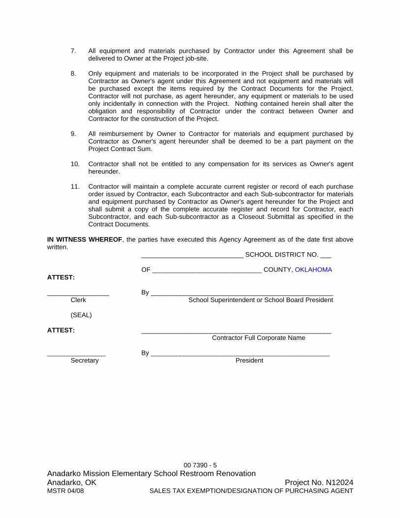
00 7390 - 5 Anadarko Mission Elementary School Restroom Renovation Anadarko, OK Project No. N12024 MSTR 04/08 SALES TAX EXEMPTION/DESIGNATION OF PURCHASING AGENT
7. All equipment and materials purchased by Contractor under this Agreement shall be delivered to Owner at the Project job-site.
8. Only equipment and materials to be incorporated in the Project shall be purchased by
Contractor as Owner's agent under this Agreement and not equipment and materials will be purchased except the items required by the Contract Documents for the Project. Contractor will not purchase, as agent hereunder, any equipment or materials to be used only incidentally in connection with the Project. Nothing contained herein shall alter the obligation and responsibility of Contractor under the contract between Owner and Contractor for the construction of the Project.
9. All reimbursement by Owner to Contractor for materials and equipment purchased by
Contractor as Owner's agent hereunder shall be deemed to be a part payment on the Project Contract Sum.
10. Contractor shall not be entitled to any compensation for its services as Owner's agent
hereunder.
11. Contractor will maintain a complete accurate current register or record of each purchase order issued by Contractor, each Subcontractor and each Sub-subcontractor for materials and equipment purchased by Contractor as Owner's agent hereunder for the Project and shall submit a copy of the complete accurate register and record for Contractor, each Subcontractor, and each Sub-subcontractor as a Closeout Submittal as specified in the Contract Documents.
IN WITNESS WHEREOF, the parties have executed this Agency Agreement as of the date first above written. ____________________________ SCHOOL DISTRICT NO. ___ OF ______________________________ COUNTY, OKLAHOMA ATTEST: _________________ By __________________________________________________ Clerk School Superintendent or School Board President (SEAL) ATTEST: ____________________________________________________ Contractor Full Corporate Name ________________ By _________________________________________________ Secretary President

01 1100 - 1 Anadarko Mission Elementary School Restroom Renovation Anadarko, OK Project No. N12024 MSTR 05/08 SUMMARY
SECTION 01 1100 BWA: ABRV N12024 SUMMARY PART 1 GENERAL 1.1 SUMMARY
A. Section Includes: 1. Contract description. 2. Work covered by Contract Documents. 3. Contractor use of site and premisis. 4. Work sequence. 5. Owner occupancy. 6. Codes and standards. 7. Permits. 8. Safety.
B. Related Documents:
1. The Contract Documents, as defined in Document 00 5214 – AIA A107 Standard Form of Agreement Between Owner and Contractor apply to the Work of this Document. Additional requirements and information necessary to complete the Work of this Section may be found in other documents.
1.2 CONTRACT DESCRIPTION
A. Contract Type: Single prime contracts based on a Stipulated Price as described in Document 00 5213 - Agreement-Stipulated Sum.
1.3 WORK COVERED BY CONTRACT DOCUMENTS
A. Provide and pay for all materials, labor, services, equipment, licenses, permits, taxes and other items necessary for the execution, installation and completion of Work indicated in Contract Documents.
B. Description: 1) Mission Elementary School Restroom Renovation of existing restrooms
and old mechanical room, including CMU demo, concrete housekeeping pad demo, new concrete pad, new metal stud & gypsum board walls, new ceramic tile walls & floors, new moisture resistant acoustical ceiling tiles, new plumbing fixtures and toilet accessories, new plumbing, new electrical and new mechanical exhaust.
C. Location : Mission Elementary School
Anadarko Public Schools 1200 South Mission Street Anadarko, Oklahoma 73005

01 1100 - 2 Anadarko Mission Elementary School Restroom Renovation Anadarko, OK Project No. N12024 MSTR 05/08 SUMMARY
1.4 CONTRACTOR USE OF SITE AND PREMISES
A. Construction Operations: Limited to areas permitted by law, ordinances, permits and as indicated on Drawings.
B. Arrange use of site and premises to allow:
1. Owner occupancy. 2. Public use of site and premises.
C. Coordinate use of site and premises with Owner's Representative.
D. Assume full responsibility for protection and safekeeping of Products under this Contract,
stored on site.
E. Move any stored Products, under Contractor's control, which interfere with operations of Owner. 1. Existing building spaces may only be used for storage with written Owner approval
prior to Bid.
F. Emergency Building Exits During Construction: Keep all exists required by code open during construction period.
G. Enforce requirements of Contract Documents regarding signs, advertisements and fires for
Subcontractors, Sub-subcontractors, Material Suppliers and other entities involved in Work.
H. If Project Site has existing Owner facilities, or Owner has existing facilities on an adjacent site, the following requirements apply. 1. Use of existing facilities by Contractor, all Subcontractors, Sub-subcontractors,
Material Suppliers and all other entities and workers involved in Work, are not permitted to use existing facilities on site including, but shall not be limited to, restroom facilities, parking lots, telephones, snack bars and dining facilities, recreation facilities, television facilities and all utilities unless specifically allowed by written agreement with Owner.
2. Entry into existing facilities not permitted unless such entry is necessary for completion of Work.
3. If Work requires that certain operations be performed in Owner existing facilities, all operations shall be scheduled to minimize interruptions in operations of Owner. Notify Owner in advance of dates and times when work is scheduled in Owner’s existing facilities.
4. If Work requires interruption of utilities servicing existing facilities or operations of Owner, the following requirements apply. a. Notify Owner, or Owner’s Representative, minimum seven (7) days before the
planned date for utility interruption. b. Obtain approval for utility interruption from Owner, or Owner’s Representative,
twenty-four (24) hours before scheduled utility interruption. If scheduled utility interruption is delayed, postponed or rescheduled, immediately notify Owner, or Owner’s Representative.
c. During the utility interruption, maintain communications with Owner, or Owner’s Representative, and report progress of Work. If delay in completing utility interruption occurs during utility interruption, immediately notify Owner, or Owner’s Representative, and notify of revised schedule for completion of utility interruption.
d. Notify Owner, or Owner’s Representative, immediately when utility is returned to full operation.

01 1100 - 3 Anadarko Mission Elementary School Restroom Renovation Anadarko, OK Project No. N12024 MSTR 05/08 SUMMARY
e. Schedule utility interruptions to minimize inconvenience to Owner or Owner’s operations. Owner may require that interruption occur after business hours, in the evening, at night, or on weekends or holidays.
I. Keep Project Site free from accumulations of waste materials or rubbish. At periodic
intervals determined by progress of Work, remove waste and rubbish from Project Site. At completion of Project, remove all waste, rubbish, temporary facilities, project signs, tools, equipment, machinery, materials and all other Contractor items.
1.6 WORK SEQUENCE
A. Construct Work continuously from Notice to Proceed until Substantial Completion for each building and Project Site.
B. Work outside normal work hours may be required to complete Work and avoid disruption of
Owner’s operations by construction activities. 1.7 OWNER OCCUPANCY
A. Owner will occupy Project existing buildings and site during the entire period of construction for the conduct of normal operations.
B. Cooperate with Owner’s Representative to minimize conflict, and to facilitate Owner’s
operations. C. Schedule Work to accommodate Owner occupancy.
1.8 CODES AND STANDARDS
A. All products, materials and construction quality shall comply with all applicable codes,
specifications, local ordinances, industry standards and utility company regulations. In no case shall work, products, or materials of a lower quality to those specified be provided in this Project, even if permitted by code.
B. In cases of difference between building codes, specifications, state laws, local ordinances,
industry standards, and utility company regulations and Contract Documents, the most stringent shall govern.
C. Non-Compliance: If Contractor performs work that does not comply with requirements of
applicable building codes, state laws, local ordinances, industry standards, and utility regulations, Contractor shall bear all costs arising in correcting deficiencies.
1.9 PERMITS
A. Contractor is responsible for scheduling inspections. Any delay in Project caused by Contractor failing to schedule or pass inspections is Contractor's responsibility.
B. Inspections by Local Authority Having Jurisdiction:
1. Do not enclose or cover items required to be inspected by Authority Having Jurisdiction until they are inspected and approved.
2. If Project does not have an Authority Having Jurisdiction, contact Architect and Engineer (if applicable) minimum three (3) days before Work is ready for inspection or tests.

01 1100 - 4 Anadarko Mission Elementary School Restroom Renovation Anadarko, OK Project No. N12024 MSTR 05/08 SUMMARY
3. Notify Authority Having Jurisdiction minimum number of days in advance of inspection as required by Authority Having Jurisdiction to schedule inspection. Verify with Authority Having Jurisdiction representative.
4. Re-inspections: Whenever inspection finds that inspected item does not pass, make required corrections and schedule a re-inspection.
1.10 SAFETY
A. Conduct all operations and all aspects of Work in safest possible manner. Comply with all Federal, State and Local Law and Regulations and accepted safe practices for use and storage of flammable, hazardous, toxic and dangerous materials, products or techniques and the health and safety of all Workers. 1. Take extra precautions to insure safety of all occupants when Work requires entry
into existing facilities of Owner. 2. All fines levied for non-compliance shall be paid by Contractor.
PART 2 PRODUCTS Not Used. PART 3 EXECUTION Not Used. END OF SECTION

01 2100 - 1 Anadarko Mission Elementary School Restroom Renovation Anadarko, OK Project No. N12024MSTR 04/08 ALLOWANCES
SECTION 01 2100 BWA MSTR 04/08 ALLOWANCES PART 1 GENERAL 1.1 SUMMARY
A. Section Includes: 1. Cash allowance. 2. Contingency allowance. 3. CSI Form 2.4A - Allowance Authorization.
B. Related Documents:
1. The Contract Documents, as defined in Document 00 7213 - General Conditions and modifications thereto, apply to the Work of this Section. Additional requirements and information necessary to complete the Work of this Section may be found in other documents.
1.2 CONTINGENCY ALLOWANCE
A. Anadarko Mission Elementary Restroom Renovation: Include in Contract, a stipulated sum of FIVE THOUSAND DOLLARS ($5,000) for use upon Owner’s instruction to cover cost of any Contract Sum increases.
B. Contractor’s costs for Products, delivery, installation, labor, insurance, payroll, taxes,
bonding, equipment rental, overhead and profit will be included in Allowance Authorization authorizing expenditure of funds from this Contingency Allowance.
C. Funds will be drawn from Contingency Allowance only upon authorization of Owner through
Architect by issuance of an executed Allowance Authorization, CSI Form 2.4A. Example copy of form located at end of this Section.
D. Provide a line item in Schedule of Values and Payment Application Continuation Sheet,
AIA Document G703 for Contingency Allowance and update each month for Allowance Authorizations.
E. At contract closeout, funds remaining in Contingency Allowance will be credited to Owner.
PART 2 PRODUCTS
Not Used PART 3 EXECUTION Not Used
END OF SECTION

01 2100 - 2 Anadarko Mission Elementary School Restroom Renovation Anadarko, OK Project No. N12024MSTR 04/08 ALLOWANCES
REPLACE THIS PAGE WITH
COPY OF CSI Form 2.4A “ALLOWANCE AUTHORIZATION”

ALLOWANCE AUTHORIZATION
Project:
To:
Re:
Authorization Number: From: Date: A/E Project Number: Contract For:
You are authorized to perform the following item(s) of work and to adjust the Allowance Sum accordingly: THIS IS NOT A CHANGE ORDER AND DOES NOT INCREASE OR DECREASE THE CONTRACT AMOUNT Original Allowance ............... .............. ............... ............... ............... .............................. $ Allowance Expenditures prior to this Authorization ............ ............... .............................. $ Allowance Balance prior to this Authorization .... ............... ............... .............................. $ Allowance will be [increased] [decreased] by this Authorization ........ .............................. $ New Allowance Balance ....... .............. ............... ............... ............... .............................. $ APPROVAL RECOMMENDED A/E By Date CONTRACTOR ACCEPTANCE Contractor By Date
OWNER APPROVAL Owner By Date
Attachments Copies: Owner Contractor Consultants File Copyright 1994, Construction Specifications Institute, 99 Canal Center Plaza, Suite 300, Alexandria, VA 22314
Page of July 1994 CSI Form 2.4A

01 2900 - 1 Anadarko Mission Elementary School Restroom Renovation Anadarko, OK Project No. N12024MSTR 09/08 PAYMENT PROCEDURES
SECTION 01 2900 BWA MSTR 09/08 PAYMENT PROCEDURES PART 1 GENERAL 1.1 SUMMARY
A. Section Includes: 1. Schedule of values. 2. Procedures for preparation and submittal of applications for payment. 3. Payments at Substantial Completion. 4. Affidavit of Payment of Debts and Claims and Release of Liens form. 5. Non-Kickback Statement. 6. AIA Document G702 - Application and Certification for Payment form. 7. AIA Document G703 - Continuation Sheet form for AIA Document G702. 8. CSI Form 2.5A - Stored Material Summary.
B. Related Documents:
1. The Contract Documents, as defined in Document 00 7213 - General Conditions and modifications thereto, apply to the Work of this Section. Additional requirements and information necessary to complete the Work of this Section may be found in other documents.
2. Document 00 5213 - Agreement-Stipulated Sum: Document executed between Owner and Contractor.
C. Related Sections:
1. Section 01 2600 - Contract Modification Procedures: Procedures for changes to the Work.
2. Section 01 2973 - Schedule of Values: Procedures for schedule of values. 3. Section 01 3300 - Submittal Procedures: Procedures for submittals. 4. Section 01 7700 - Closeout Procedures: Final payment.
1.2 SCHEDULE OF VALUES
A. Refer to Section 01 2973 - Schedule of Values. 1.3 FORMAT
A. Forms: 1. Application and Certificate: AIA Document G702 - Application and Certificate for
Payment. 2. Continuation Form: AIA Document G703 - Continuation Sheet. 3. Submit on original AIA Document forms or computer generated forms from AIA
Electronic Format program. Photo copies of AIA forms Not Permitted. a. Other forms or computer forms not generated from AIA Electronic Format
program may or may not be permitted at the discretion of Architect. b. Upon receipt of Notice to Proceed, submit Contractor proposed alternate AIA
Document G702 and G703 forms to Architect for review and approval. 4. Submit forms typewritten. Handwritten forms not permitted.
B. For each item, provide a column for listing each of the following:

01 2900 - 2 Anadarko Mission Elementary School Restroom Renovation Anadarko, OK Project No. N12024MSTR 09/08 PAYMENT PROCEDURES
1. Item Number. 2. Description of work. 3. Scheduled Values. 4. Previous Applications. 5. Work in Place under this Application. 6. Authorized Change Orders. 7. Total Completed to Date of Application. 8. Percentage of Completion. 9. Balance to Finish.
10. Retainage. 1.4 PREPARATION OF APPLICATIONS
A. All signatures shall be in Blue Ink to clearly identify each document as an original signed document.
B. Prepare as specified in Document 00 7213 - General Conditions.
C. Include statement on application as specified in Document 00 7213 – General Conditions
for materials stored on the Project Site but not yet incorporated into Work.
D. Do not include request for payment for materials stored off Project Site. Architect will not approve and Owner will not pay for any materials stored off Project Site.
E. Execute certification by signature of Contractor or Contractor authorized officer.
F. Prepare application on same form and in same format as approved Schedule of Values.
1. Use data from approved Schedule of Values. 2. Provide dollar value in each column for each line item for portion of work performed. 3. Provide an overall project summary percentage complete and payment amount for
each Application for Payment as specified in Section 01 2900 - Payment Procedures.
G. List each authorized Change Order as an extension on AIA Document G703 - Continuation Sheet, listing Change Order number and dollar amount as for an original item of Work.
H. Starting with second Application for Payment, include an executed and notarized Affidavit
of Payment of Debts and Claims and Release of Liens with each Application for Payment. 1. Submital of Affidavit required by Contractor and each Subcontractor, Sub-
subcontractor and material supplier who performed work covered by the Application of the payment period immediately preceeding the Application being submitted.
2. Contractor is responsible to secure and submit proper Affidavits. 3. Required Affidavit is attached at end of this Section. 4. Non-Kickback Statement form attached at end of this Section.
I. Prepare Application for Final Payment as specified in Document 00 5213 - Agreement-
Stipulated Sum, Document 00 7213 - General Conditions, and Section 01 7300 - Execution.
1.5 SUBMITTAL PROCEDURES
A. Submit Application for Payment to Architect on or before date stipulated in Document 00 5213, Subparagraph 5.1.3 . Regardless of Contractor standard billing process, Contractor shall organize and setup billing process for THIS PROJECT as required to allow time to

01 2900 - 3 Anadarko Mission Elementary School Restroom Renovation Anadarko, OK Project No. N12024MSTR 09/08 PAYMENT PROCEDURES
obtain subcontractor invoices, prepare required documents, prepare Application for Payment forms, and mail Payment Application Package to Architect for receipt by Architect on or before the 10th of the month. 1. Submit Application on or before the 10th of the month. No exception permitted. 2. Provided Application for Payment is received by Architect as specified, Owner will
make payment to Contractor on or before the 15th of the following month. If Application for Payment is received by Architect after specified date, payment will be made by Owner no later than 60 days after Architect receives Application for Payment.
3. Contractor submittal on or before stipulated date is critical for receiving required approvals, processing and payment by Owner.
4. Contractor submittal after stipulated date may delay approvals and processing and delay Owner payment as indicated in Document 00 5214 , Subparagraph 4.1.2.
5. By failing to submit on or before stipulated date, Contractor expressly assumes risk of all delays to payment and waives all claims for damages or additional payment for any such delays to payment.
B. Submit three (3) executed and notarized original copies of each Application for Payment
with original seals and signatures.
C. Submit updated construction schedule with each Application for Payment.
D. Submit Applications at intervals stipulated in Document 00 5213 - Agreement-Stipulated Sum.
E. Transmit each Payment Request Package to Architect with AIA Form G810 - Transmittal
Letter or other Architect approved transmittal form or letter containing the same information as AIA Document G810. 1. Deliver official submittal of original documents in person or by courier, overnight
delivery service or U.S. Mail postpaid. 2. Do not fax official submittal. Contractor may fax a notification to Architect, on
Contractor’s letterhead, that a Payment Request Package is being sent and when it should arrive. Notification may include a copy of AIA Document G702 and G703 for Architect information.
F. Contents of first Payment Request Package shall include the following:
1. Transmittal - AIA Document G810. 2. Application and Certification for Payment - AIA Document G702. 3. Continuation Sheet - AIA Document G703. 4. Updated Construction Progress Schedule. 5. Non-Kickback Statement.
G. Contents of subsequent Payment Request Package shall include the following:
1. Transmittal - AIA Document G810. 2. Application and Certification for Payment - AIA Document G702. 3. Continuation Sheet - AIA Document G703. 4. Stored Material Summary - CSI Form 2.5A as applicable. 5. Updated Construction Progress Schedule. 6. Contractor Affidavit of Payment of Debts and Claims and Release of Liens. 7. Affidavit of Payment of Debts and Claims and Release of Liens for each
Subcontractor, Sub-subcontractor or material supplier as applicable. 8. Request for Contract Time Extension as defined within Document 00 7385 -
Determination and Extension of Contract Time.

01 2900 - 4 Anadarko Mission Elementary School Restroom Renovation Anadarko, OK Project No. N12024MSTR 09/08 PAYMENT PROCEDURES
9. Non-Kickback Statement. 1.6 INCOMPLETE OR INCORRECT SUBMITTALS
A. Incomplete Submittals: Processing will stop for Payment Request Packages received by Architect that do not include all required items. Architect will contact Contractor and advise Contractor of missing items. Contractor is responsible for sending Architect items missing from Payment Request Package. Payment processing will not start until Payment Request Package is complete.
B. Incorrect Submittals: Payment Request Packages that are incorrectly submitted,
incorrectly assembled or have incorrect data will be returned to Contractor for correction. 1. Packages submitted on photocopies of AIA forms rather than original AIA forms will
be returned to Contractor to prepare on original AIA forms. 2. Handwritten forms will be returned to Contractor to prepare in typewritten form. 3. Payment Request Packages with Continuation Sheets containing major incorrect
percentage complete numbers may be marked-up and returned to Contractor for correction.
4. Minor percentage complete numbers may be corrected by Architect and processed with corrected percentages and payment amount.
5. Determination of whether to return Payment Request Package or to process an Architect mark-up of Payment Request Package is at the discretion of the Architect.
C. Contractor is responsible for Payment Request Package processing being stopped due to
submittal of incomplete or incorrect Payment Request Package. 1.7 SUBSTANTIATING DATA
A. If Contractor is making application for payment on account of materials and equipment delivered, suitably stored at site for subsequent incorporation in Work and properly invoiced, Contractor shall provide substantiating data showing flow of materials and equipment in and out of storage on CSI Form 2.5A - Stored Material Summary.
B. When Architect requires substantiating information, submit data justifying dollar amounts in
question.
C. Provide one (1) copy of data with cover letter for each copy of submittal. Show application number and date, and line item by number and description.
D. Include the following with application:
1. Partial release of liens from major subcontractors and vendors. 2. Section 01 3216 - Construction Progress Schedules; Revised and current
construction schedule as specified. 1.8 SUBSTANTIAL COMPLETION
A. It is the duty, responsibility and obligation of Contractor to achieve Substantial Completion within Contract Time stipulated in Document 00 5213 - Agreement-Stipulated Sum, and the Notice to Proceed.
B. If Contractor does not achieve Substantial Completion within Contract Time, Owner may
suspend further Progress Payments until Work is Substantially Complete as determined by Architect.

01 2900 - 5 Anadarko Mission Elementary School Restroom Renovation Anadarko, OK Project No. N12024MSTR 09/08 PAYMENT PROCEDURES
C. If Contractor does not achieve Substantial Completion within 30 calendar days after
expiration of Contract Time, Contract Sum will be adjusted as provided in Document 00 7213 – General Conditions in direct relation to true and accurate additional direct costs incurred by Owner, including Architect’s additional fees.
D. Contractor expressly assumes risk of all delays to Work and waives all claims for damages
or additional payment for any such delays to Work.
E. Nothing in Contract Documents limit Owner’s full rights and remedies as allowed by law should delays in Work exceed 30 calendar days beyond Contract Time as established in the Agreement.
PART 2 PRODUCTS
Not Used. PART 3 EXECUTION
Not Used.
END OF SECTION

01 2900 - 6 Anadarko Mission Elementary School Restroom Renovation Anadarko, OK Project No. N12024MSTR 09/08 PAYMENT PROCEDURES
AFFIDAVIT OF PAYMENT OF DEBTS AND CLAIMS AND RELEASE OF LIENS TO: ________________________________________________ (Project Owner name & address)
________________________________________________
________________________________________________
________________________________________________ (Project name & address)
________________________________________________
________________________________________________ By this instrument the undersigned who performs the _____________ work hereby certifies that on this date, or anytime prior thereto, except as listed below, he has paid in full or has otherwise satisfied all obligations for all materials and equipment furnished, for all work, labor, and services performed and for all known indebtedness and claims against the undersigned for damages arising in any manner on or against the PROJECT, its land, improvements and equipment of every kind. The undersigned hereby certifies that he has received all payments currently due under his contract for work on the Project (except retainage). Therefore, the undersigned does hereby waive and/or release any and all liens against the PROPERTY PROJECT and as of the _______ day of ______________, 20_____.
( ) Partial
( ) Final (including retainage) _______________________________ (Name of Contractor/Subcontractor) By: ___________________________ Title: ________________________

01 2900 - 7 Anadarko Mission Elementary School Restroom Renovation Anadarko, OK Project No. N12024MSTR 09/08 PAYMENT PROCEDURES
STATE OF ___________________( ) COUNTY OF__________________( )
BEFORE ME, the undersigned authority, on this day personally appeared ____________________; ________________________________ of ________________________ known to me to be the person whose name is subscribed to the foregoing instrument, and, being first duly sworn, acknowledged to me that he executed the same for the purposes and consideration therein expressed and declared to me that the statements contained therein are true. SWORN AND SUBSCRIBED to before me this _______ day of _________, 20___ My commission expires: _____________________ _____________________________
NOTARY PUBLIC in and for said County and State. This affidavit and Release shall be executed by the CONTRACTOR, all of his sub-contractors, material suppliers and lessors of equipment; or an independent contractor, who expects payment of funds from the current Progress Payment from the OWNER to the CONTRACTOR, or a Payment directly from the OWNER. Execution hereof is conditioned upon the bank's clearance of any check given in payment of the current Progress Payment.
END OF AFFIDAVIT

01 2900 - 8 Anadarko Mission Elementary School Restroom Renovation Anadarko, OK Project No. N12024MSTR 09/08 PAYMENT PROCEDURES
NON-KICKBACK STATEMENT (Affidavit for Payment of Claim)
STATE OF ) ) ss. COUNTY OF ) The undersigned ___________________________________________, of lawful age, being first duly sworn, on oath states: that this invoice or claim is true and correct; the work, services, or materials as shown by this invoice or claim have been completed or supplied in accordance with the plans, specifications, orders or requests furnished the claimant: that claimant has made no payment directly or indirectly to any elected official, officer, or employee of Independent School District Number 08i020 of Anadarko, Caddo County, Oklahoma (Anadarko Public Schools), of money or other thing of value to obtain payment of the invoice or procure the contract or purchase order pursuant to which an invoice is required. Affiant NOTARY PUBLIC Subscribed and sworn to before me this ___ day of ______________, 20___. Notary My Commission Expires: ACCORDING TO OKLAHOMA STATE LAW, ALL INVOICES OF $2,000 OR MORE FROM AN ARCHITECT, CONTRACTOR, ENGINEER OR SUPPLIER OF MATERIAL MUST HAVE THE ABOVE AFFIDAVIT SIGNED, NOTARIZED AND RETURNED BEFORE PAYMENT CAN BE PROCESSED
END OF STATEMENT

AP
PL
ICA
TIO
N A
ND
CE
RT
IFIC
AT
ION
FO
R P
AY
ME
NT
AIA
DO
CU
MEN
T G
702
PA
GE
ON
E O
FP
AG
ES
TO
OW
NE
R:
PR
OJE
CT
:A
PP
LIC
AT
ION
NO
:D
istr
ibut
ion
to:
OW
NE
R
AR
CH
ITE
CT
PE
RIO
D T
O:
CO
NT
RA
CT
OR
FR
OM
CO
NT
RA
CT
OR
:V
IA A
RC
HIT
EC
T:
PR
OJE
CT
NO
S:
CO
NT
RA
CT
FO
R:
CO
NT
RA
CT
DA
TE
:
CO
NT
RA
CT
OR
'S A
PP
LIC
AT
ION
FO
R P
AY
ME
NT
The
und
ersi
gned
Con
trac
tor
cert
ifie
s th
at to
the
best
of
the
Con
trac
tor's
kno
wle
dge,
A
ppli
cati
on is
mad
e fo
r pa
ymen
t, as
sho
wn
belo
w, i
n co
nnec
tion
wit
h th
e C
ontr
act.
info
rmat
ion
and
beli
ef th
e W
ork
cove
red
by th
is A
ppli
cati
on f
or P
aym
ent h
as b
een
Con
tinu
atio
n S
heet
, AIA
Doc
umen
t G70
3, is
att
ache
d.co
mpl
eted
in a
ccor
danc
e w
ith
the
Con
trac
t Doc
umen
ts, t
hat a
ll a
mou
nts
have
bee
n pa
id b
y
the
Con
trac
tor
for
Wor
k fo
r w
hich
pre
viou
s C
erti
fica
tes
for
Pay
men
t wer
e is
sued
and
paym
ents
rec
eive
d fr
om th
e O
wne
r, a
nd th
at c
urre
nt p
aym
ent s
how
n he
rein
is n
ow d
ue.
1. O
RIG
INA
L C
ON
TR
AC
T S
UM
$
2. N
et c
hang
e by
Cha
nge
Ord
ers
$C
ON
TR
AC
TO
R:
3. C
ON
TR
AC
T S
UM
TO
DA
TE
(L
ine
1 ±
2)
$4.
TO
TA
L C
OM
PL
ET
ED
& S
TO
RE
D T
O$
DA
TE
(C
olum
n G
on
G70
3)B
y: D
ate:
5. R
ET
AIN
AG
E:
a.%
of
Com
plet
ed W
ork
$
Sta
te o
f:C
ount
y of
:(C
olum
n D
+ E
on
G70
3)S
ubsc
ribe
d an
d sw
orn
to b
efor
e m
e th
is
day
of
b.
% o
f S
tore
d M
ater
ial
$
Not
ary
Pub
lic:
(Col
umn
F o
n G
703)
My
Com
mis
sion
exp
ires
:
Tot
al R
etai
nage
(L
ines
5a
+ 5
b or
Tot
al in
Col
umn
I of
G70
3)
$0.
00A
RC
HIT
EC
T'S
CE
RT
IFIC
AT
E F
OR
PA
YM
EN
T6.
TO
TA
L E
AR
NE
D L
ES
S R
ET
AIN
AG
E
$0.
00In
acc
orda
nce
wit
h th
e C
ontr
act D
ocum
ents
, bas
ed o
n on
-sit
e ob
serv
atio
ns a
nd th
e da
ta(L
ine
4 L
ess
Lin
e 5
Tot
al)
com
pris
ing
the
appl
icat
ion,
the
Arc
hite
ct c
erti
fies
to th
e O
wne
r th
at to
the
best
of
the
7. L
ES
S P
RE
VIO
US
CE
RT
IFIC
AT
ES
FO
R A
rchi
tect
's k
now
ledg
e, in
form
atio
n an
d be
lief
the
Wor
k ha
s pr
ogre
ssed
as
indi
cate
d,
PA
YM
EN
T (
Lin
e 6
from
pri
or C
erti
fica
te)
$th
e qu
alit
y of
the
Wor
k is
in a
ccor
danc
e w
ith
the
Con
trac
t Doc
umen
ts, a
nd th
e C
ontr
acto
r8.
CU
RR
EN
T P
AY
ME
NT
DU
E
$0.
00is
ent
itle
d to
pay
men
t of
the
AM
OU
NT
CE
RT
IFIE
D.
9. B
AL
AN
CE
TO
FIN
ISH
, IN
CL
UD
ING
RE
TA
INA
GE
$
0.00
(Lin
e 3
less
Lin
e 6)
AM
OU
NT
CE
RT
IFIE
D .
. . .
. . .
. . .
. $
CH
AN
GE
OR
DE
R S
UM
MA
RY
AD
DIT
ION
SD
ED
UC
TIO
NS
(Atta
ch e
xpla
natio
n if
amou
nt c
ertif
ied
diffe
rs fr
om th
e am
ount
app
lied.
Initi
al a
ll fig
ures
on
this
T
otal
cha
nges
app
rove
dAp
plic
atio
n an
d on
the
Con
tinua
tion
Shee
t tha
t are
cha
nged
to c
onfo
rm w
ith th
e am
ount
cer
tifie
d.)
i
n pr
evio
us m
onth
s by
Ow
ner
AR
CH
ITE
CT
:
T
otal
app
rove
d th
is M
onth
By:
Dat
e:
T
OT
AL
S$0
.00
$0.0
0T
his
Cer
tifi
cate
is n
ot n
egot
iabl
e. T
he A
MO
UN
T C
ER
TIF
IED
is p
ayab
le o
nly
to th
e C
ontr
acto
r na
med
her
ein.
Iss
uanc
e, p
aym
ent a
nd a
ccep
tanc
e of
pay
men
t are
wit
hout
NE
T C
HA
NG
ES
by
Cha
nge
Ord
er$0
.00
prej
udic
e to
any
rig
hts
of th
e O
wne
r or
Con
trac
tor
unde
r th
is C
ontr
act.
AIA
DO
CU
ME
NT
G70
2 ·
AP
PLI
CA
TIO
N A
ND
CE
RT
IFIC
AT
ION
FO
R P
AY
ME
NT
· 1
992
ED
ITIO
N ·
AIA
® ·
© 1
992
TH
E A
ME
RIC
AN
INS
TIT
UT
E O
F A
RC
HIT
EC
TS
, 173
5 N
EW
YO
RK
AV
E.,
N.W
., W
AS
HIN
GT
ON
, DC
200
06-5
292
Use
rs m
ay o
bta
in v
alid
atio
n o
f th
is d
ocu
men
t b
y re
qu
esti
ng
a c
om
ple
ted
AIA
Do
cum
ent
D40
1 -
Cer
tifi
cati
on
of
Do
cum
ent'
s A
uth
enti
city
fro
m t
he
Lic
ense
e.

CO
NT
INU
AT
ION
SH
EE
TAI
A D
OC
UM
ENT
G70
3 P
AG
E
OF
P
AG
ES
AIA
Doc
umen
t G70
2, A
PP
LIC
AT
ION
AN
D C
ER
TIF
ICA
TIO
N F
OR
PA
YM
EN
T, c
onta
inin
gA
PP
LIC
AT
ION
NO
:C
ontr
acto
r's s
igne
d ce
rtif
icat
ion
is a
ttac
hed.
AP
PL
ICA
TIO
N D
AT
E:
In ta
bula
tion
s be
low
, am
ount
s ar
e st
ated
to th
e ne
ares
t dol
lar.
PE
RIO
D T
O:
Use
Col
umn
I on
Con
trac
ts w
here
var
iabl
e re
tain
age
for
line
item
s m
ay a
pply
.A
RC
HIT
EC
T'S
PR
OJE
CT
NO
:
AB
CD
EF
GH
IIT
EM
DE
SC
RIP
TIO
N O
F W
OR
KS
CH
ED
UL
ED
WO
RK
CO
MP
LE
TE
DM
AT
ER
IAL
ST
OT
AL
%B
AL
AN
CE
RE
TA
INA
GE
NO
.V
AL
UE
FR
OM
PR
EV
IOU
ST
HIS
PE
RIO
DP
RE
SE
NT
LY
CO
MP
LE
TE
D(G
÷ C
)T
O F
INIS
H(I
F V
AR
IAB
LE
AP
PL
ICA
TIO
NS
TO
RE
DA
ND
ST
OR
ED
(C -
G)
RA
TE
)(D
+ E
)(N
OT
IN
TO
DA
TE
D O
R E
)(D
+E
+F
)
GR
AN
D T
OT
AL
S$0
.00
$0.0
0$0
.00
$0.0
0$0
.00
0.00
%$0
.00
Use
rs m
ay o
bta
in v
alid
atio
n o
f th
is d
ocu
men
t b
y re
qu
esti
ng
of
the
licen
se a
co
mp
lete
d A
IA D
ocu
men
t D
401
- C
erti
fica
tio
n o
f D
ocu
men
t's
Au
then
tici
ty
AIA
DO
CU
ME
NT
G70
3 ·
CO
NT
INU
AT
ION
SH
EE
T F
OR
G70
2 ·
1992
ED
ITIO
N ·
AIA
® ·
© 1
992
TH
E A
ME
RIC
AN
INS
TIT
UT
E O
F A
RC
HIT
EC
TS
, 173
5 N
EW
YO
RK
AV
EN
UE
, N.W
., W
AS
HIN
GT
ON
, D.C
. 20
006-
5232
G70
3-19
92

ST
OR
ED
MA
TE
RIA
L S
UM
MA
RY
Proj
ect:
App
lica
tion
Per
iod:
Ow
ner:
App
lica
tion
Num
ber:
A/E
Pro
ject
Num
ber:
App
lica
tion
Dat
e:
STO
RE
D P
RE
VIO
US
STO
RE
D T
HIS
MO
NT
HIN
CO
RP
OR
AT
ED
IN
WO
RK
INV
OIC
EN
O.
SUB
MIT
TA
LT
RA
NSM
ITT
AL
NO
.M
AT
ER
IAL
DE
SCR
IPT
ION
DA
TE
(MO
/YR
)A
MO
UN
T($
)A
MO
UN
T($
)SU
BT
OT
AL
($)
DA
TE
(MO
/YR
)A
MO
UN
T($
)
MA
TE
RIA
LS
RE
MA
ININ
GIN
ST
OR
AG
E($
)
-$
-$
-$
-$
-$
-$
-$
-$
-$
-$
-$
-$
-$
-$
-$
-$
-$
-$
-$
-$
-$
-$
-$
-$
-$
-$
-$
-$
-$
-$
-$
-$
-$
-$
-
$
Cop
yrig
ht 1
994,
Con
stru
ctio
n Sp
ecif
icat
ions
Ins
titut
e,Pa
ge _
_ of
__
July
199
499
Can
al C
ente
r Pl
aza,
Sui
te 3
00 A
lexa
ndri
a, V
A 2
2314
CSI
For
m 2
.5A

01 2973 - 1 Anadarko Mission Elementary School Restroom Renovation Anadarko, OK Project No. N12024MSTR 0909 SCHEDULE OF VALUES
SECTION 01 2973 BWA MSTR 0909 SCHEDULE OF VALUES PART 1 GENERAL
1.1 SUMMARY
A. Section Includes: 1. Submittals. 2. Schedule of values (one per building, if applicable). 3. General Conditions breakdown. 4. Individual Section breakdown. 5. Individual Section breakdown - material and labor. 6. Schedule of values breakdown example form, located at end of Section.
B. Related Documents:
1. The Contract Documents, as defined in Document 00 7213 - General Conditions and modifications thereto, apply to the Work of this Section. Additional requirements and information necessary to complete the Work of this Section may be found in other documents.
2. Document 00 2113 - Instructions to Bidders: Requirements and procedures for bidding.
3. Document 00 2213 - Supplementary Instructions to Bidders
C. Related Sections: 1. Section 01 2900 - Payment Procedures: Applications for payment. 2. Section 01 4200 - References: Definitions. 3. Section 01 6213 - Product Substitution Procedures.
1.2 SUBMITTALS
A. Section 01 3300 - Submittal Procedures: Requirements for submittals.
B Submit a printed schedule on AIA Form G703 - Application and Certificate for Payment Continuation Sheet itemizing all contract costs with breakdown as specified herein.
C. Submit three copies of Schedule of Values within 10 days of Notice to Proceed.
D. Failure of Contractor to submit complete and accurate Schedule of Values within specified
time and as specified in this Section will cause processing of Contractor Payment Request Packages to stop. Payment processing will not start until Schedule of Values has been submitted, reviewed and accepted by Architect.
1.3 SCHEDULE OF VALUES
A. Contractor is responsible for and shall provide a complete and detailed accounting to
Owner of all Contractor costs for this Project. Owner requires that Contractor indicate where each dollar of Contract Sum is allocated.
B. The Schedule of Values will be used by Architect as a basis for reviewing Contractor's
Applications for Payment.

01 2973 - 2 Anadarko Mission Elementary School Restroom Renovation Anadarko, OK Project No. N12024MSTR 0909 SCHEDULE OF VALUES
C. Schedule of Values shall be broken down by Document and Specification utilizing Table of
Contents of this Project Manual. Identify each line item with number and title of Document or Specification Section.
D. Include in each line item, the amount of Allowances specified in this section. For unit cost
Allowances, identify quantities taken from Contract Documents multiplied by the unit cost to achieve the total for the item.
E. Revise schedule as necessary to reflect approved Change Orders with each Application for
Payment.
F. Refer to attached Sample Form for Schedule of Values. 1. Sample Form is not an exact breakdown for this Project, but an example of how the
Schedule of Values for this Project should appear. Section numbers and titles in the Sample Form are not specifically prepared for this Project.
2. Sample Form is not an exact copy of AIA Document G703, only a representation of AIA Document G703.
1.4 GENERAL CONDITIONS BREAKDOWN
A. Contracting Requirements: Provide breakdown for the following: 1. Document 00 6100 - Bonds: Cost of bonding Project. 2. Document 00 7213 - General Conditions: Cost of miscellaneous Contractor
expenses applicable to Project. 3. Document 00 7316 - Insurance Requirements: Cost of Insurance for Project.
B. General Requirements: Provide breakdown for the following: 1. Summary: Cost of Contractor mobilization. 2. Section 01 7700 - Closeout Procedures: Cost for Final Cleaning.
C. Contractor Overhead and Profit: Cost for Contractor overhead and Contractor Profit.
1.5 INDIVIDUAL SECTION BREAKDOWN
A. Provide cost for Work for both material and labor as line item for all Specification Sections not specified for further breakdown.
1.6 INDIVIDUAL SECTION BREAKDOWN - MATERIAL AND LABOR
A. Provide cost for Work for material as a separate line item and labor as a separate line item for Specification Sections
PART 2 PRODUCTS Not Used. PART 3 EXECUTION Not Used. END OF SECTION

Continuation Sheet AIA Document G703 Page 1 of 3 Section 01 2974
CONTINUATION SHEET-AIA DOCUMENT G703 PAGE 1 OF 3
AIA Document G702. APPLICATION AND CERTIFICATE OF PAYMENT. Containing APPLICATION NUMBER: Contractor's signed Certificate is Attached in tabulations below, amounts are stated APPLICATION DATE: to the nearest dollar. PERIOD FROM: TO: Use Column I on Contracts where variable retainage for line items may apply. ARCHITECTS PROJECT No:
A B C D E F G
H I
WORK COMPLETED
THIS APPLICATION
ITEM DESCRIPTION OF WORK SCHEDULED VALUE
PREVIOUS APPLICA- TIONS
WORK IN PLACE
STORED MATERIALS (NOT IN D or E)
TOTAL COMPLETED & STORED TO DATE (D+E+F)
% (C-G)
BALANCE TO FINISH (C-G)
RETAINAGE
Contracting Requirements 00 6100 Bonds 00 7213 General Conditions Superintendence/Contractor Quality Control Mobilization Permits & Fees Misc. GC Expenses 00 7316 Insurance Requirements Division 1 General Requirements 01 4523 Testing and Inspection Services Division 3 Concrete 03 0586 Vapor Barrier 03 1100 Concrete Forming 03 2000 Concrete Reinforcement 03 3000 Cast-In-Place Concrete Building Concrete 03 3500 Concrete Finishing 03 3900 Concrete Curing Division 4 Masonry 04 2111 Brick Veneer 04 2200 Concrete Masonry Units 04 2206 Masonry Screen Walls - Concrete Division 5 Metals 05 4000 Cold-Formed Metal Framing 05 5000 Metal Fabrications Division 6 Wood and Plastic 06 2000 Finish Carpentry 06 4102 Custom Architectural Wood Casework Division 12 Furnishings 12 3624 Plastic Laminate Countertop Division 13 Special Construction 13 3421 Pre-Engineered Metal Buildings Material Erection

Continuation Sheet AIA Document G703 Page 2 of 3 Section 01 2974
CONTINUATION SHEET-AIA DOCUMENT G703 PAGE 2 OF 3
AIA Document G702. APPLICATION AND CERTIFICATE OF PAYMENT. Containing APPLICATION NUMBER: Contractor's signed Certificate is Attached in tabulations below, amounts are stated APPLICATION DATE: to the nearest dollar. PERIOD FROM: TO: Use Column I on Contracts where variable retainage for line items may apply. ARCHITECTS PROJECT No:
A B C D E F G
H I
WORK COMPLETED
THIS APPLICATION
ITEM DESCRIPTION OF WORK SCHEDULED VALUE
PREVIOUS APPLIC.
WORK IN PLACE
STORED MATERIALS (NOT IN D or E)
TOTAL COMPLETED & STORED TO DATE (D+E+F)
% (C-G)
BALANCE TO FINISH (C-G)
RETAINAGE
Division 21 Fire Suppression 21 1300 Fire-Suppression Sprinklers System Division 22 Plumbing 22 0000 General Plumbing 22 1000 Piping and Pumps
Division 23 HVAC 23 0500 Mechanical Systems, Testing, Adjusting and Balancing 23 0700 HVAC Insulation 23 3200 Air Outlets and Inlets 23 3300 Air Duct Accessories 23 3313 Fire and Smoke Dampers 23 3400 HVAC Fans 23 6200 Single Packaged HVAC Units Division 25 Integrated Automation 25 3700 Integrated Intercommunication System Division 26 Electrical 26 0500 Electrical Identification 26 0513 Conduit 26 0515 Building Wire and Cable 26 0518 Boxes 26 0521 Wiring Devices 26 0526 Electrical Grounding 26 0529 Hangers and Supports 26 1800 Motor and Circuit Disconnects 26 1805 Fuses 26 2400 Panelboards 26 5000 Lamps 26 5100 Ballasts and Accessories 26 5105 Interior Building Lighting Division 27 Communications 27 3200 Telephone Service, Pathway and Wiring

Continuation Sheet AIA Document G703 Page 3 of 3 Section 01 2974
CONTINUATION SHEET-AIA DOCUMENT G703 PAGE 3 OF 3
AIA Document G702. APPLICATION AND CERTIFICATE OF PAYMENT. Containing APPLICATION NUMBER: Contractor's signed Certificate is Attached in tabulations below, amounts are stated APPLICATION DATE: to the nearest dollar. PERIOD FROM: TO: Use Column I on Contracts where variable retainage for line items may apply. ARCHITECTS PROJECT No:
A B C D E F G
H I
WORK COMPLETED
THIS APPLICATION
ITEM DESCRIPTION OF WORK SCHEDULED VALUE
PREVIOUS APPLIC.
WORK IN PLACE
STORED MATERIALS (NOT IN D or E)
TOTAL COMPLETED & STORED TO DATE (D+E+F)
% (C-G)
BALANCE TO FINISH (C-G)
RETAINAGE
Division 28 Electronic Safety & Security 28 0513 Fire Alarm and Detection System Division 31 Earthwork 31 1000 Site Clearing 31 2200 Grading 31 2316 Spread and Continuous Footings 31 2324 Fill and Backfill 31 2333 Trenching for Site Utilities 31 2500 Erosion and Sedimentation Control 31 3116 Soil Treatment for Termite Control 31 3216 Excavation 31 3200 Soil Stabilization Division 32 Exterior Improvements 32 1314 Concrete Walks and Pads 32 1541 Gravel Surfacing 32 9223 Sodding Division 33 Utilities 33 4915 Storm Drainage
Categories and subcategories to be added or deleted for each project as required. G.C. profit and overhead shall be prorated to each item/ category as applicable. Subcontractors cost, profit and overhead shall be included in their respective item/category. After each line item, under Description of Work, G.C. shall indicate in parenthesis, as a percentage, each item/categories material/subcontractors cost.
End of Document
01 3300 - 1 Anadarko Mission Elementary School Restroom Renovation Anadarko, OK Project No. N12024MSTR 0309 SUBMITTAL PROCEDURES
SECTION 01 3300 BWA MSTR 0309 SUBMITTAL PROCEDURES PART 1 GENERAL 1.1 SUMMARY
A Section Includes: 1. Procedures. 2. Re-submittals. 3. Schedule of Submittals. 4. Schedule of Values. 5. Shop Drawings. 6. Product Data. 7. Samples. 8. NOT USED. 9. Manufacturer's Instructions. 10. Certificates. 11. Closeout Submittals. 12. Contractor Action. 13. Architect Action. 14. Architect’s Consultant Action. 15. AIA Document G810 - Transmittal Letter. 16. CSI Form 12.2A - Submittal Checklist. 17. CSI Form 12.1B - Submittal Log.
B. Related Documents:
1. The Contract Documents, as defined in Document 00 7213 - General Conditions and modifications thereto, apply to the Work of this Section. Additional requirements and information necessary to complete the Work of this Section may be found in other documents.
C. Related Sections:
1. Section 01 2973 - Schedule of Values: Submittal requirements. 2. Section 01 4500 - Quality Control: Field samples/mock-ups. 3. Section 01 7800 - Closeout Submittals: Requirements for closeout and Project
Record Submittals. 1.2 DEFINITIONS
A. Refer to Document 00 7213 - General Conditions; Article 3.12 for definitions of the following: 1. Product Data 2. Samples 3. Shop Drawings 4. Submittal Package 5. Submittals
1.3 PROCEDURES

01 3300 - 3 Anadarko Mission Elementary School Restroom Renovation Anadarko, OK Project No. N12024MSTR 0309 SUBMITTAL PROCEDURES
2. Identify deviations from Contract Documents. a. Identify deviations from specified products or procedures. b. Identify deviations from specified standards.
3. Failure of Contractor to identify deviations will result in Submittal being returned to Contractor marked “Incomplete-Rejected.” a. Upon receipt of returned item, revise Submittal to identify deviations and
resubmit to Architect for review. 4. Provide space for Contractor and Architect or Architect’s Consultant review stamps.
J. Submittals that will be forwarded to Architect’s Consultants shall be prepared in
conformance with this Section and in conformance with requirements contained in other Sections outlining Architect’s Consultants procedures.
K. Submit initial Construction Schedule and Schedule of Values, as specified after Award of
Contract. After review by Architect revise and resubmit as required. Submit revised schedules as specified reflecting changes since previous submittal.
L. Comply with Construction Schedule for Submittals related to Work progress. Coordinate
Submittals of related items.
M. Submittal to Architect for review is for the limited purpose of checking for conformance information given and the design concept expressed in the Contract Documents. 1. Samples will be reviewed only for aesthetic, color or finish selection.
N. After Architect review of Submittal, revise and resubmit as required, identifying changes
made since previous submittal. 1. Failure of Contractor to identify changes will result in item being returned to
Contractor marked “Incomplete-Rejected.” a. Upon receipt of returned item, revise item to identify changes and resubmit.
O. Distribute copies of reviewed Submittals to concerned persons. Instruct recipients to
promptly report any inability to comply with provisions.
P. Maintain copies of Submittals at site as specified in Document 00 7213 - General Conditions.
Q. Maintain Project Record Submittals for Owner's Record submitted at Project Closeout as
specified in Section 01 7800 - Closeout Submittals. 1.4 RESUBMITTALS
A. Resubmit Submittals received back from Architect marked “Revise and Resubmit,” “Incomplete-Rejected," or “Provide Contract Specified Item.”
B. Re-submittal shall include entire original submittal with corrected items clearly identified by
circling, highlighting or other Architect approved method. Provide clear, concise and complete written description of what revisions to original submittal have been made and where.
C. Re-submittal of only revised data without entire original submittal not permitted. Any re-
submittals without the entire original submittal, revised data, identification of revised data, and written description of revisions will result in re-submittal being returned to Contractor marked “Incomplete-Rejected.”

01 3300 - 2 Anadarko Mission Elementary School Restroom Renovation Anadarko, OK Project No. N12024MSTR 0309 SUBMITTAL PROCEDURES
A. Submit complete Submittal Packages. Coordinate each Submittal with Submittal requirements defined within Technical Section. Submittals covering the same Broad Grouping of the Work shall be submitted at the same time. 1. Broad Groupings of Work may be defined by Contractor provided that Submittals
within Broad Groupings are identified separately by Section number with separate transmittal.
2. Using the Table of Contents from Project Manual, prepare Submittals, and Submittal Packages to identify contents of each Submittal.
B. Architect will not accept partial Submittals.
1. Any partial submittal received will be returned to Contractor without action.
C. Architect will not accept Submittals which obviously have not been reviewed by the Contractor before submittal to Architect. Any such submittal received will be returned to Contractor without action.
D. Make Submittals promptly in accordance with Submittal Schedule. Failure of Contractor to
transmit Submittals to Architect in sufficient time for review shall not constitute adequate cause for extension of Contract Time.
E. Submittals shall be fastened in binders or folders, or otherwise assembled and organized
into an easily manageable format and accompanied by separate transmittal form for each Submittal. 1. Submittals covering the same Broad Grouping of the Work shall be submitted at the
same time. 2. Loose or fragmented submittals will be returned to Contractor without action.
F. Each Submittal shall contain the following information:
1. Date of Submittal and dates of previous Submittals. 2. Project title and Architect’s project number. 3. Names of Contractor, Subcontractor, Supplier and Manufacturer, as applicable. 4. Field dimensions, clearly identified as field dimensions. 5. Location where material and/or equipment will be installed. Relation of product to
adjacent or critical features of the Work or materials. 6. Contractor’s stamp, initialed and signed, certifying Contractor review of Submittals,
verification of products, field measurements and field construction criteria, as well as coordination of information within Submittal with requirements of the Work and Contract Documents as a whole.
G. Transmit each Submittal to Architect with AIA Form G810 “Transmittal Letter” or other
Architect approved transmittal form or letter containing the same information as AIA Form G810. 1. Submittal Packages and Submittals shall be delivered in person or by courier,
overnight delivery service or U.S. Mail postpaid. 2. Do not fax submittals.
H. Sequentially number the transmittal form for each Submittal. Revise Submittals with
original number and a sequential alphabetic suffix.
I. Transmit each Submittal within Submittal Package identifying the Project, Contractor, subcontractor, and major supplier. 1. Prominently identify Submittal by Specification Section and pertinent Drawing or
Detail number, as appropriate.

01 3300 - 4 Anadarko Mission Elementary School Restroom Renovation Anadarko, OK Project No. N12024MSTR 0309 SUBMITTAL PROCEDURES
D. If Architect or Architect’s Consultants are required to perform a second, or more, re-
submittal review because the re-submittal is incomplete or incorrect and must be returned to Contractor marked "Incomplete-Rejected:" 1. Architect will invoice Owner for additional services by the Architect or Architect’s
Consultants. 2. Contractor shall pay for Architect’s or Architect’s Consultant additional services by
deductive change order. 3. Change order will be issued deducting the additional service amount from the
Contract Sum. 1.5 SCHEDULE OF SUBMITTALS
A. Submit three (3) copies of proposed Schedule of Submittals to Architect, within (10) days after Date of Notice to Proceed. List all items that require submittal for review by Architect in accordance with Document 00 7213 - General Conditions.
B. Submit three (3) copies of final Schedule of Submittals to Architect within five (5) days after
receipt of proposed Schedule of Submittals review from Architect.
C. Schedule of Submittals: Include the following. 1. Indicate type of Submittal; Product Data, Shop Drawing, Sample, Certificate, or other
Submittal. 2. Identify by Specification Section number, Specification paragraph number where item
is specified, and description of item being submitted. 3. Indicate scheduled date for initial submittal, date for approval, and date for possible
re-submittal for each submittal. 4. Indicate number of submittal copies required for each submittal.
D. Coordinate Schedule of Submittals with Construction Schedule. Revise and update
Schedule of Submittals when required by changes in the Construction Schedule. Provide Architect with updated schedules within five (5) days of date schedule is revised.
E. Prepare Schedule of Submittals on CSI Form 12.2A - Submittal Checklist, CSI Form 12.1B
- Submittal Log or other Architect approved form or document Contractor prefers to use. 1.6 SCHEDULE OF VALUES
A. Refer to Section 01 2973 - Schedule of Values. 1.7 SHOP DRAWINGS
A. Refer to Document 00 7213 - General Conditions.
B. It is the sole responsibility of Contractor, Subcontractors or Material Suppliers to prepare their own drawings or offer materials as required by their submittals.
C. Shop Drawings shall be presented in clear and thorough manner. Plan drawings shall be
identified by reference to sheet numbers and room numbers indicated on Contract Documents. Detail drawings shall be identified by reference mark to sheet and plan drawing indicated on Contract Documents. 1. Indicate special utility and electrical characteristics, utility connection requirements
and location of utility outlets for service for functional equipment and appliances.

01 3300 - 5 Anadarko Mission Elementary School Restroom Renovation Anadarko, OK Project No. N12024MSTR 0309 SUBMITTAL PROCEDURES
D. Submit five (5) copies for Submittals reviewed only by Architect:
1. Three (3) copies will be returned to Contractor. 2. One (1) copy will be returned to Contractor for Contractor to keep, assemble and
furnish to Owner as a Record Submittal as specified in Section 01 7800 - Closeout Submittals.
3. One (1) copy will be kept by Architect. 1.8 PRODUCT DATA
A. Refer to Document 00 7213 - General Conditions.
B. Mark each copy to identify applicable products, models, options, and other data;
supplement manufacturers' standard data to provide information unique to Work. Indicate performance characteristics and capacities. Indicate dimensions and clearance required. Indicate connections to building systems and adjacent materials. Include manufacturers' installation instructions when required by individual Specification Section.
C. Manufacturer’s standard schematic drawings and diagrams shall be modified to delete
information which is not applicable to Work.
D. Submit five (5) copies for Submittals reviewed only by Architect: 1. Three (3) copies will be returned to Contractor. 2. One (1) copy will be returned to Contractor for Contractor to keep, assemble and
furnish to Owner as a Record Submittal as specified in Section 01 7800 - Closeout Submittals.
3. One (1) copy will be kept by Architect. 1.9 SAMPLES
A. Refer to Document 00 7213 - General Conditions.
B. Submit samples for selection of finishes maximum 60 days after date of Notice to Proceed. Color samples shall be submitted before date for Payment Request No. 2 submittal. Payment Request No. 2 will not be processed until all color samples are submitted.
C. Submit all samples together as one (1) Color Sample Submittal Package.
D. Submit full range of manufacturer's standard colors, textures, and patterns for Architect
selection.
E. Submit samples to illustrate functional characteristics of the product, with integral parts and attachment devices. Coordinate submittal of different categories for interfacing work.
F. Include identification on each sample, giving full information.
G. Submit number of samples specified in respective Specification section; two (2) will be
retained by Architect. Reviewed samples which may be used in the Work are indicated in the Specification Section.

01 3300 - 6 Anadarko Mission Elementary School Restroom Renovation Anadarko, OK Project No. N12024MSTR 0309 SUBMITTAL PROCEDURES
H. Approved samples may be returned in the form of a Color Board. Maintain Color Board and other returned samples at Project Site for comparison of functional and aesthetic characteristics of the Work. 1. One (1) copy of each approved sample shall be used for Project Record Submittals.
1.10 Not Used 1.11 MANUFACTURER'S INSTRUCTIONS
A. Submittal of manufacturer's installation instructions is for information only and will not be reviewed by Architect.
B. When required in individual Specification Section, submit manufacturer's printed
instructions for delivery, storage, assembly, installation (start-up) adjusting, and finishing, in quantities specified for Product Data.
C. Indicate special procedures, perimeter conditions requiring special attention, and special
environmental criteria required for application or installation.
D. Clearly identify conflicts between requirements of Contract Documents and Manufacturer’s Instructions.
1.12 CERTIFICATES
A. When specified in individual Specification Sections, submit certification by manufacturer to Architect, in quantities specified for Product Data.
B. Indicate material or Product conforms to or exceeds specified requirements. Submit
supporting reference data, affidavits, and certifications as appropriate. 1. Certification shall contain the following statement:
“(NAME OF MANUFACTURER) hereby certifies that the requirements of the Contract Documents for (NAME, NUMBER AND ADDRESS OF PROJECT) have been carefully studied and that (NAME OF PRODUCT OR MATERIAL) conforms to, or exceeds these requirements.”
C. Certificates may be recent or previous test results on material or Product, but must be
acceptable to Architect.
D. Contractor Installation Certification: When specified in individual Specification Section, submit notarized Contractor Installation Certification form as a Record Document Closeout Submittal.
1.13 CLOSEOUT SUBMITTALS
A. Specified in Section 01 7800 - Closeout Submittals.
B. Project Record Submittals: Maintain one (1) set of Shop Drawings, Product Data, Samples and Manufacturer’s Instructions as specified in Section 01 7800 - Closeout Submittals.
1.14 CONTRACTOR ACTION
A. Preparation of overall Submittal Package is the responsibility of Contractor.

01 3300 - 7 Anadarko Mission Elementary School Restroom Renovation Anadarko, OK Project No. N12024MSTR 0309 SUBMITTAL PROCEDURES
1. Preparation of trade specific Submittals is the responsibility of specific trade subcontractor.
2. Preparation of product specific Submittals is the responsibility of the product manufacturer representative.
B. Prepare Submittals and submit to Architect, after Contractor review and approval in
accordance with the approved Submittal Schedule. 1. Refer to Document 00 7213 – General Conditions.
C. Receive Submittals from subcontractors, material suppliers and others.
D. Review Submittals and re-Submittals from subcontractors, material suppliers and others for
conformance with the Contract Documents before submitting to Architect. Review shall be thorough, complete and detailed. 1. Return incomplete or incorrect Submittals for correction and re-submittal to
Contractor. 2. Receive corrected re-Submittals form subcontractors, material suppliers and others;
review for required corrections and conformance with Contract Documents.
E. Apply Contractor's stamp, signed or initialed certifying that review, approval, verification of Products required, field dimensions, adjacent construction Work, and coordination of information is in accordance with the requirements of the Work and Contract Documents.
1.15 ARCHITECT ACTION
A. For Submittals where action and return is required or requested, Architect will review each Submittal, mark to indicate action taken, and return to Contractor. 1. Compliance with specified characteristics is the Contractor's responsibility. 2. Submittals for Information, Closeout Documents, Record Documents and other
Submittals for similar purposes, no action will be taken.
B. Action Stamp: Architect will stamp each Submittal with a uniform, self-explanatory action stamp. The stamp will be appropriately marked, as follows, to indicate the action taken. 1. "Reviewed": Final Unrestricted Release. Where Submittals are marked "Reviewed",
that part of the Work covered by the Submittal may precede provided it complies with requirements of the Contract Documents; final acceptance will depend upon that compliance.
2. "Make Corrections Noted": Final-But-Restricted Release. When Submittals are marked "Make Corrections Noted", that part of the Work covered by the Submittals may precede provided it complies with notations or corrections on the Submittal and requirements of the Contract Documents; final acceptance will depend on that compliance.
3. "Revise and Resubmit": Returned for Re-submittal. When Submittal is marked "Revise and Resubmit," do not proceed with that part of the Work covered by the Submittal, including purchasing, fabrication, delivery, or other activity. Revise or prepare a new Submittal in accordance with the notations; resubmit without delay. Repeat if necessary to obtain a different action mark. a. Do not permit Submittals marked "Revise and Resubmit," to be used at the
Project site, or elsewhere where Work is in progress. 4. "Incomplete-Rejected": When Submittal is marked "Incomplete-Rejected," do not
proceed with that part of the Work covered by the Submittal, including purchasing, fabrication, delivery, or other activity. Product Shall Not Be Used.

01 3300 - 8 Anadarko Mission Elementary School Restroom Renovation Anadarko, OK Project No. N12024MSTR 0309 SUBMITTAL PROCEDURES
a. Do not permit Submittals marked "Incomplete-Rejected," to be used at the Project site, or elsewhere where Work is in progress.
5. Provide Contract Specified Item: When Submittal is marked “Provide Contract Specified Item,” provide item as specified in the Contract Documents. No deviations permitted.
1.16 ARCHITECT’S CONSULTANT ACTION
A. Architect will forward appropriate Submittals to Consultant.
B. Consultant will review Submittals and take action as indicated on Consultant’s Review Stamp.
C. Architect will return Submittals to Contractor with attached Architect’s Submittal Transmittal
indicating Architect Action. PART 2 PRODUCTS
Not Used. PART 3 EXECUTION
Not Used.
END OF SECTION

AIA®
Document G810TM – 2001 Transmittal Letter
AIA Document G810™ – 2001. Copyright © 1970 and 2001 by The American Institute of Architects. All rights reserved. WARNING: This AIA® Document is protected by U.S. Copyright Law and International Treaties. Unauthorized reproduction or distribution of this AIA® Document, or any portion of it, may result in severe civil and criminal penalties, and will be prosecuted to the maximum extent possible under the law. This draft was produced by AIA software at 09:27:16 on 07/31/2008 under Order No.1000341532_1 which expires on 2/3/2009, and is not for resale. User Notes: (2766192238)
1
PROJECT: (Name and address) [Insert Project Name] [Address] [City, ST Zip]
TO: (Name and address)
FROM: (Name and address)
WE TRANSMIT: Attached Under separate cover
VIA: Overnight delivery Mail E-mail Courier Fax Other FOR: Approval / Action Information Use as requested Comment Distribution Other THE FOLLOWING: Drawings Specifications Digital Files Submittals Other
NO. OF COPIES DATE FORMAT DESCRIPTION REMARKS: BY: COPIES TO:

SU
BM
ITT
AL
C
HE
CK
LIS
T
Proj
ect:
Ow
ner:
A/E
Pro
ject
Num
ber:
Con
trac
tor:
PR
EC
ON
ST
RU
CT
ION
PO
ST
-CO
NS
TR
UC
TIO
N S
PE
CIF
ICA
TIO
N S
EC
TIO
N
(Nu
mb
er a
nd
Tit
le)
PR
OD
. D
AT
A
SH
OP
D
WG
.
SA
MP
. C
AL
C.
DG
N.
DA
TA
TE
ST
R
PT
.
CE
RT
. Q
UA
LF
.
MFG
. IN
ST
.
CO
NF
.
MFG
. FL
D.
RP
T.
RE
C.
DO
C.
O /
M
DA
TA
WR
TY
.
O =
Req
uire
d
X =
Rec
eive
d
R =
Rej
ecte
d / R
esub
mit
A =
App
rove
d C
opyr
ight
199
6, C
onst
ruct
ion
Spe
cifi
cati
ons
Inst
itut
e,
99 C
anal
Cen
ter
Pla
za, S
uite
300
Ale
xand
ria,
VA
223
14
Pag
e
of
Sep
tem
ber
1996
C
SI
For
m 1
2.2A
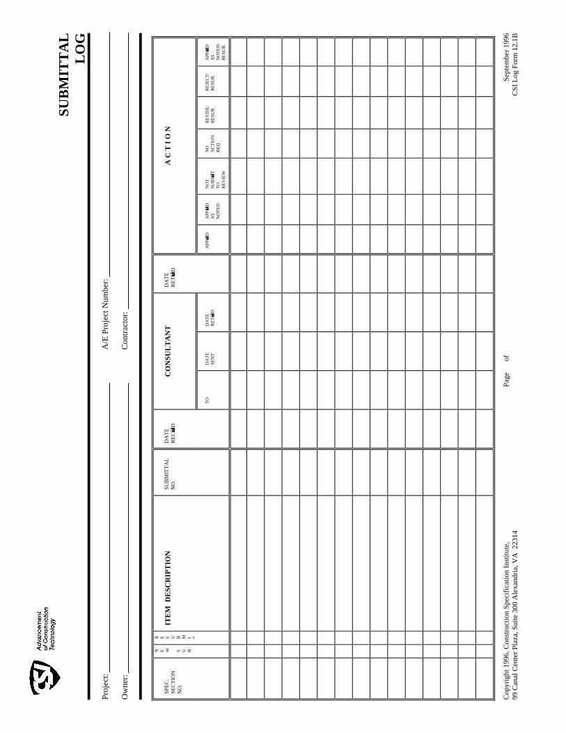
SU
BM
ITT
AL
L
OG
Pr
ojec
t:
O
wne
r:
A/E
Pro
ject
Num
ber:
Con
trac
tor:
SP
EC
. S
EC
TIO
N
NO
.
N
E
W
S
U
B
R
E
S
U
B
M
I T
ITE
M D
ES
CR
IPT
ION
SU
BM
ITT
AL
N
O.
DA
TE
R
EC
D
CO
NS
UL
TA
NT
DA
TE
R
ET
D
A C
T I
O N
TO
D
AT
E
SE
NT
DA
TE
R
ET
D
A
PP
D
AP
P
D
AS
N
OT
ED
NO
T
SU
BJ
T
TO
R
EV
IEW
NO
A
CT
ION
R
EQ
.
RE
VIS
E/
RE
SUB
.
RE
JEC
T/
RE
SUB
.
AP
P
D
AS
N
OT
ED
/ R
ESU
B.
Cop
yrig
ht 1
996,
Con
stru
ctio
n S
peci
fica
tion
Ins
titu
te,
99 C
anal
Cen
ter
Pla
za, S
uite
300
Ale
xand
ria,
VA
223
14
Pag
e
of
Sep
tem
ber
1996
C
SI
Log
For
m 1
2.1B

01 3516 - 1 Anadarko Mission Elementary School Restroom Renovation Anadarko, OK Project No. N12024MSTR 04/08 ALTERATION PROJECT PROCEDURES
SECTION 01 3516 BWA MSTR 04/08 ALTERATION PROJECT PROCEDURES PART 1 GENERAL 1.1 SUMMARY
A. Section Includes: 1. Products and installation for patching and extending Work. 2. Transition and adjustments. 3. Repair of damaged surfaces, finishes, and cleaning.
B. Related Documents:
1. The Contract Documents, as defined in Document 00 7213 - General Conditions and modifications thereto, apply to the Work of this Section. Additional requirements and information necessary to complete the Work of this Section may be found in other documents.
C. Related Sections:
1. Section 01 5000 - Temporary Facilities and Controls: Temporary enclosures, protection of installed work, and cleaning during construction.
2. Section 01 7329 - Cutting and Patching: Requirements for cutting and patching. PART 2 PRODUCTS 2.1 PRODUCTS FOR PATCHING AND EXTENDING WORK
A. New Materials: As specified in product sections; match existing Products and work for patching and extending work.
B. Type and Quality of Existing Products: Determine by inspecting and testing Products
where necessary, referring to existing Work as a standard. PART 3 EXECUTION 3.1 EXAMINATION
A. Section 01 7300 - Execution: Verification of existing conditions before starting work.
B. Verification of Conditions: Verify that field measurements, surfaces, substrates and conditions are as indicated, and ready for alteration work. 1. Examine elements subject to damage or movement during alterations. 2. After uncovering existing Work, assess conditions affecting performance of work. 3. Verify that demolition is complete and areas are ready for installation of new Work.
C. Report in writing to Architect and Owner’s Representative prevailing conditions that will
adversely affect satisfactory execution of the Work of this Section. Do not proceed with Work until unsatisfactory conditions are corrected.

01 3516 - 2 Anadarko Mission Elementary School Restroom Renovation Anadarko, OK Project No. N12024MSTR 04/08 ALTERATION PROJECT PROCEDURES
D. By starting Work, Contractor accepts conditions and assumes responsibility for correcting unsuitable conditions encountered at no additional cost to Owner.
3.2 PREPARATION
A. Cut, move, or remove items as necessary for access to alterations and renovation Work. Replace and restore at completion.
B. Remove unsuitable material not marked for salvage, such as rotted wood, corroded metals,
and deteriorated masonry and concrete. Replace materials as specified for finished Work.
C. Remove debris and abandoned items from area and from concealed spaces.
D. Prepare surface and remove surface finishes to provide for proper installation of new work and finishes.
E. Close openings in exterior surfaces to protect existing work and salvage items from
weather and extremes of temperature and humidity. Insulate ductwork and piping to prevent condensation in exposed areas.
3.3 INSTALLATION
A. Coordinate work of alterations and renovations to expedite completion to accommodate Owner occupancy.
B. Remove, cut, and patch Work in a manner to minimize damage and to provide a means of
restoring Products and finishes to specified condition in accordance with Section 01 7329 - Cutting and Patching.
C. Re-cover and refinish Work that exposes mechanical and electrical work exposed
accidentally during the work.
D. Install Products as specified in individual Sections and on Drawings. 3.4 TRANSITIONS
A. Where new Work abuts or aligns with existing, perform a smooth and even transition. Patch Work to match existing adjacent Work in texture and appearance.
B. When finished surfaces are cut so that a smooth transition with new Work is not possible,
terminate existing surface along a straight line at a natural line of division and make recommendation to Architect.
3.5 ADJUSTMENTS
A. Where removal of partitions or walls results in adjacent spaces becoming one, rework floors, walls, and ceilings to a smooth plane without breaks, steps, or bulkheads.
B. Where a change of plane of 1/4 inch or more occurs, submit recommendation for providing
a smooth transition for Architect review.
C. Trim existing doors as necessary to clear new floor finish. Refinish trim as required.

01 3516 - 3 Anadarko Mission Elementary School Restroom Renovation Anadarko, OK Project No. N12024MSTR 04/08 ALTERATION PROJECT PROCEDURES
3.6 REPAIR OF DAMAGED SURFACES
A. Patch or replace portions of existing surfaces which are damaged, lifted, discolored, or showing other imperfections.
B. Repair substrate prior to patching finish.
3.7 FINISHES
A. Finish surfaces as specified in individual Product sections.
B. Finish patches to produce uniform finish and texture over entire area. When finish cannot be matched, refinish entire surface to nearest intersections.
END OF SECTION

01 4200 - 1 Anadarko Mission Elementary School Restroom Renovation Anadarko, OK Project No. N12024MSTR 04/08 REFERENCES
SECTION 01 4200 BWA MSTR 04/08 REFERENCES PART 1 - GENERAL 1.1 SUMMARY
A. Section Includes: 1. Quality assurance. 2. Reference standards. 3. Abbreviations. 4. Definitions.
B. Related Documents:
1. The Contract Documents, as defined in Document 00 7213 - General Conditions and modifications thereto, apply to the Work of this Section. Additional requirements and information necessary to complete the Work of this Section may be found in other documents.
C. Related Sections:
1. Section 01 6200 - Product Options: Definitions. 1.2 QUALITY ASSURANCE
A. For Products or workmanship specified by association, trade, or other consensus standards, comply with requirements of standard, except when more rigid requirements are specified or are required by applicable codes. Such standards are made a part of Contract Documents by reference.
B. Conform to reference standard by date of issue current on original date of issue indicated
on Contract Documents.
C. Obtain copies of standards when required by Contract Documents.
D. Maintain copy at Project Site during submittals, planning, and progress of specific Work, until Final Acceptance.
E. Should specified reference standards conflict with Contract Documents, request
clarification from the Architect before proceeding.
F. The contractual relationship, duties, and responsibilities of the parties in Contract nor those of the Architect shall not be altered from Contract Documents by mention or inference otherwise in any reference document.
1.3 REFERENCE STANDARDS
A. Conflicting Requirements: Where compliance with two or more standards is specified, and the standards may establish different or conflicting requirements for minimum quantities or quality levels. Refer requirements that are different, but apparently equal, and uncertainties to Architect for decision before proceeding. 1. Minimum Quantity or Quality Levels: Quantity or quality level shown or specified
shall be minimum provided or performed. Actual installation may comply exactly with minimum quantity or quality specified, or it may exceed minimum within reasonable limits. In complying with these requirements, indicated numeric values are minimum

01 4200 - 2 Anadarko Mission Elementary School Restroom Renovation Anadarko, OK Project No. N12024MSTR 04/08 REFERENCES
or maximum, as appropriate for context of requirements. Refer uncertainties to Architect for decision before proceeding.
B. Copies of Standards: Each entity engaged in construction on Project is required to be
familiar with industry standards applicable to that entity's construction activity. Copies of applicable standards are not bound with Contract Documents. 1. Where copies of standards are needed for performance of a required construction
activity, Contractor shall obtain copies directly from publication source.
C. Standard Specification, Manufacturer’s Specifications, Manufacturer’s Published Instructions: These terms and other similar terms shall be defined as the latest edition, complete with all revisions, as published or printed on or before the Bid Date as indicated in the Invitation to Bid.
1.4 ABBREVIATIONS
A. Abbreviations and Names: Trade association names and titles of general standards are frequently abbreviated. Where such acronyms or abbreviations are used in Specifications or other Contract Documents, they mean the recognized name of trade association, standards generating organization, authority having jurisdiction, or other entity applicable to context of text provision.
1.5 DEFINITIONS (People and Entities)
A. Authority Having Jurisdiction: Local, State, or Federal government body having jurisdiction over the Work or the Project.
B. Contractor: Defined in Document 00 7213 – General Conditions. When used on the
Drawings or in the Specifications the term “Contractor” may mean the Contractor, Sub-contractor, Subsubcontractor, Material Supplier or similar entity as defined in Document 00 7213 – General Conditions, if the Contractor has divided the Work among such persons and entities.
C. Engineer/Engineer of Record: The engineer is the person lawfully licensed to practice
engineering in a particular engineering area such as civil, structural, mechanical, electrical, and other areas as made be indicated.
D. Installer: The Contractor or another entity engaged by the Contractor, either as an
employee, subcontractor, or contractor of lower tier, to perform a particular construction activity, including installation, erection, application, unpacking, assembly, placing, finishing, curing, adjusting, cleaning, protection, or similar operations. Installers are required to be experienced in the operations they are engaged to perform. 1. Experienced: The term "experienced," when used with the term "installer," means
having a minimum number of years experience on projects similar in size and scope to this Project, being familiar with the special requirements indicated, and having complied with requirements of the authority having jurisdiction.
2. Trades: Using terms such as "carpentry" does not imply that certain construction activities must be performed by accredited or unionized individuals of a corresponding generic name, such as "carpenter." It also does not imply that requirements specified apply exclusively to tradespersons of the corresponding generic name.
E. Manufacturer: A person, firm, or corporation who makes Products.
F. Material Supplier: See Supplier.

01 4200 - 3 Anadarko Mission Elementary School Restroom Renovation Anadarko, OK Project No. N12024MSTR 04/08 REFERENCES
G. Project Field Superintendent: The Contractor's representative at the site who is
responsible for continuous field supervision, coordination, quality control, completion of the work, and, unless another person is designated in writing by the Contractor to the Architect, for the prevention of accidents.
H. Subcontractor: An individual, firm or corporation having a direct contract with Contractor or
with any other Subcontractor for the performance of a part of the Work at the Project Site.
I. Supplier: A manufacturer, fabricator, supplier, distributor, materialman or vendor having a direct contract with Contractor or with any Subcontractor to furnish materials or equipment to be incorporated in the Work by Contractor or any Subcontractor, but does not perform labor at Project Site.
J. Testing Laboratory: An independent entity engaged to perform specific inspections or
tests, either at the Project Site or elsewhere, and to report on and, if required, to interpret results of those inspections or tests.
K. Trade: See Installer.
L. Utility: Local Utility.
1.6 DEFINITIONS (Things, Services, and Dispositions)
A. Acceptable: Satisfactory to and approved by the Architect.
B. Approve: The term "approved," when used in conjunction with the Architect's action on the Contractor's submittals, applications, and requests, is limited to the Architect’s duties and responsibilities as stated in the Contract.
C. Change Order: A modification to a contract.
D. Clarification Drawing: A graphic interpretation of the Drawings or other Contract
Documents issued by the Architect.
E. Construction Occupancy Date: The date that the Contractor may assume occupancy and begin that portion of the Work within the existing facilities of the Owner. The Construction Occupancy Date may or may not coincide with the Date of the Notice to Proceed and more than one Construction Occupancy Date may be established for different portions of the existing facilities of the Owner.
F. Construction Operations: Activities of the Contractor at the Project Site.
G. Directed: Instructed by the Architect.
H. Experienced (Qualified): When used to describe the "installer", "fabricator", or similar
terms; a person, firm or corporation skilled through observation or of participation in the particular activities required to complete the Work or a portion of the Work to the degree of the quality specified.
I. Final Connections: Complete plumbing, mechanical, and electrical connections as
required and recommended by manufacturer for optimum operation of equipment.

01 4200 - 4 Anadarko Mission Elementary School Restroom Renovation Anadarko, OK Project No. N12024MSTR 04/08 REFERENCES
J. Indicated: The term "indicated" refers to graphic representations, notes or schedules on the Drawings, or other Paragraphs or Schedules in the Specifications, and similar requirements in the Contract Documents. Where terms such as "shown," "noted," "scheduled," and "specified" are used, it is to help the reader locate the reference. Location is not limited.
K. Install: Operations at the Project Site including the actual unloading, unpacking, assembly,
erecting, placing, anchoring, applying, working to dimension, finishing, curing, protecting, cleaning, and similar operations.
L. Mobilization: To establish and commence work activity at the Project Site.
M. Notice to Proceed: A written instrument by the Owner which will authorize the Contractor
to begin the Work and which will be issued after execution of the Agreement. The Date of the Notice to Proceed shall be the starting date of the Contract Time. The Contractor shall not begin the Work until the Notice to Proceed has been issued.
N. Partial Occupancy: Partial Occupancy occurs when the Owner begins to occupy parts of
the project for its own purposes, such as early fixture set-up, merchandising, etc. Partial Occupancy shall not constitute acceptance of Work not in accordance with the Contract Documents.
O. Premises: Space or property made available to the Contractor for constructing the Work.
P. Project Site: The space available to the Contractor for performing construction operations,
either exclusively or in conjunction, with others performing other work as part of the Project. The extent of the Project Site is shown on the Drawings and may or may not be identical with the description of the land on which the Project is to be built.
Q. Receive: Accepting a delivery. (Entity responsible for accepting a delivery.)
R. Regulations: The term "Regulations" includes laws, ordinances, statutes, and lawful orders
issued by authorities having jurisdiction, as well as rules, conventions, and agreements within the construction industry that control performance of the Work.
S. Reviewed: Examined and found acceptable by the Architect.
T. Substantial Completion: The stage in the progress of the Work when the Work or
designated portion thereof is sufficiently complete in accordance with the Contract Documents so the Owner can occupy or utilize the Work for its intended use.
U. Substitution: A product that is exchanged for another of the same function.
V. Supply: To supply and deliver, unload, inspect for damage (same as furnish).
W. Temporary Facilities: Those portions of the Work which shall be removed from the Project
Site by the Contractor before the completion of the Work and shall include, but shall not be limited to, such items as shoring, temporary bracing, concrete formwork, temporary guardrail and other safety items, security fences, office and storage structures, and scaffolding and hoisting equipment.
X. Unacceptable: Determined not satisfactory by the Architect.

01 4200 - 5 Anadarko Mission Elementary School Restroom Renovation Anadarko, OK Project No. N12024MSTR 04/08 REFERENCES
PART 2 PRODUCTS Not Used. PART 3 EXECUTION Not Used.
END OF SECTION
01 6211 - 1 Anadarko Mission Elementary School Restroom Renovation Anadarko, OK Project No. N12024MSTR 04/08 ASBESTOS PROHIBITION
SECTION 01 6211 BWA MSTR 04/08 ASBESTOS PROHIBITION FOR PUBLIC WORKS PROJECTS PART 1 GENERAL 1.1 SUMMARY
A. Section Includes: 1. Compliance with applicable law. 2. Intent. 3. Statement. 4. Certification forms, located at end of Section.
B. Related Documents:
1. The Contract Documents, as defined in Document 00 7213 - General Conditions and modifications thereto, apply to the Work of this Section. Additional requirements and information necessary to complete the Work of this Section may be found in other documents.
C. Related Sections:
1. Section 01 6200 - Product Requirements: Product options and procedures. 1.2 COMPLIANCE WITH APPLICABLE LAW
A. Contractor shall fully comply with the requirements of Public Law 99-519 the Asbestos Hazard Emergency Response Act of 1986 and the United States Environmental Protection Agency Regulations promulgated October 30, 1987, Federal Register Volume 52, No. 210.
B. Contractor shall enforce compliance with this law and these regulations to all
Subcontractors, Sub-subcontractors and material suppliers on this Project. Each Subcontract, Sub-subcontract and purchase order applicable to this Project shall contain Paragraph A. directly above.
1.3 INTENT
A. It is the specific intent of this Section of the Specification to prohibit the use or installation of any product, material, component of any product or material assembled from two or more separate products or materials, or any other item into the Work which contains more than one (1) percent asbestos by weight, and, thus, would be classified by Law as an Asbestos Containing Building Material.
1.4 STATEMENT
A. The Contractor shall execute, and shall cause each and every Subcontractor, Sub-subcontractor and material supplier on this Project to execute the Federal General Contractors Certification of Compliance with Asbestos Restrictions or the Federal Subcontractors or Material Suppliers Certification of Compliance with Asbestos Restrictions.
B. Contractor shall deliver certification as defined above to Owner as part of Closeout
Documents Package.

01 6211 - 2 Anadarko Mission Elementary School Restroom Renovation Anadarko, OK Project No. N12024MSTR 04/08 ASBESTOS PROHIBITION
C. Copies of applicable certifications are attached to this Section.
PART 2 PRODUCTS Not Used. PART 3 EXECUTION Not Used. END OF SECTION

01 6211 - 3 Anadarko Mission Elementary School Restroom Renovation Anadarko, OK Project No. N12024MSTR 04/08 ASBESTOS PROHIBITION
FEDERAL ASBESTOS "STATEMENT" ALTERNATIVE TO INSPECTION TO:
RE: Sirs, As the Architect of Record for the above referenced project and having prepared the Contract Documents, Construction Drawings and Specifications, Boynton Williams and Associates issued a Certificate of Substantial Completion . In the performance of our professional services for the preparation of Contract Documents, Construction Drawings and Specifications for the above referenced Project, no materials or products were knowingly specified, or called for, in any Construction Document that contained more than one percent (1%) asbestos by weight, within the meaning of Public Law 99-519 together with the United States Environmental Protection Agency Regulations, Section 763.83 promulgated October 30, 1987, Federal Register, Volume 52, No. 210 defining Asbestos Containing Building Material (ACBM). We are enclosing a Federal General Contractors Certificate of Compliance with Asbestos Restrictions which completes the requirements for the Exclusion as allowed in Section 763.99 (a)(7) of the United States Environmental Protection Agency Regulations, promulgated October 30, 1987, Federal Register, Volume 52, No. 210.
Boynton Williams & Associates
BY: _____________________________________ President
DATE:
Subscribed and Sworn to Before Me This day of , 20 .
Notary Public My Commission Expires ____________.
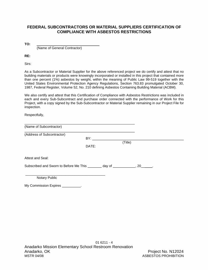
01 6211 - 4 Anadarko Mission Elementary School Restroom Renovation Anadarko, OK Project No. N12024MSTR 04/08 ASBESTOS PROHIBITION
FEDERAL SUBCONTRACTORS OR MATERIAL SUPPLIERS CERTIFICATION OF COMPLIANCE WITH ASBESTOS RESTRICTIONS
TO: _________________________________
(Name of General Contractor) RE: Sirs: As a Subcontractor or Material Supplier for the above referenced project we do certify and attest that no building materials or products were knowingly incorporated or installed in this project that contained more than one percent (1%) asbestos by weight, within the meaning of Public Law 99-519 together with the United States Environmental Protection Agency Regulations, Section 763.83 promulgated October 30, 1987, Federal Register, Volume 52, No. 210 defining Asbestos Containing Building Material (ACBM). We also certify and attest that this Certification of Compliance with Asbestos Restrictions was included in each and every Sub-Subcontract and purchase order connected with the performance of Work for this Project, with a copy signed by the Sub-Subcontractor or Material Supplier remaining in our Project File for inspection. Respectfully, (Name of Subcontractor) (Address of Subcontractor)
BY: (Title)
DATE: Attest and Seal: Subscribed and Sworn to Before Me This day of , 20 ____. __________________________________________
Notary Public My Commission Expires .

01 6211 - 5 Anadarko Mission Elementary School Restroom Renovation Anadarko, OK Project No. N12024MSTR 04/08 ASBESTOS PROHIBITION
FEDERAL GENERAL CONTRACTORS CERTIFICATION OF COMPLIANCE WITH ASBESTOS RESTRICTIONS
TO:
RE: Sirs: As a General Contractor for the above referenced project we do certify and attest that no building materials or products were knowingly incorporated or installed in this Project that contained more than one percent (1%) asbestos by weight, within the meaning of Public Law 99-519 together with the United States Environmental Protection Agency Regulations, Section 763.83 promulgated October 30, 1987, Federal Register, Volume 52, No. 210 defining Asbestos Containing Building Material (ACBM). We also certify and attest that this Certification of Compliance with Asbestos Restrictions was included in each and every Sub-contract and purchase order connected with the performance of Work for this Project, with a copy signed by the Subcontractor or Material Supplier remaining in our Project File for inspection. Respectfully, (Name of Contractor) (Address of Contractor)
BY: ________________________________ (Title)
DATE:
Attest and Seal: Subscribed and Sworn to Before Me This day of , 20 __.
Notary Public
My Commission Expires .

01 6213 - 1 Anadarko Mission Elementary School Restroom Renovation Anadarko, OK Project No. N12024MSTR 04/08 PRODUCT SUBSTITUTION PROCEDURES
SECTION 01 6213 BWA MSTR 04/08 PRODUCT SUBSTITUTION PROCEDURES PART 1 GENERAL 1.1 SUMMARY
A. Section Includes: 1. Product substitutions. 2. Substitution request package. 3. Product substitution procedures during bidding. 4. Product substitution procedures after Award of Contract. 5. Architect’s review. 6. CSI Form 1.5C - Substitution Request (During the Bidding Phase). 7. CSI Form 13.1A - Substitution Request (After the Bidding Phase).
B. Related Documents:
1. The Contract Documents, as defined in Document 00 7213 - General Conditions and modifications thereto, apply to the Work of this Section. Additional requirements and information necessary to complete the Work of this Section may be found in other documents. a. Document 00 2113 - Instructions to Bidders. b. Document 00 2218 - Additional Instructions to Bidders.
C. Related Sections:
1. Section 01 2600 - Contract Modification Procedures: Change order procedures. 2. Section 01 6200 - Product Options: Product options.
1.2 DEFINITIONS
A. Substitution: Changes in products, materials, equipment and methods of construction from those required by the Contract Documents and proposed by Contractor.
1.3 PRODUCT SUBSTITUTIONS
A. During the Bidding Phase: Submit proposed substitutions to Architect minimum five (5) days before Bid Date. Requests received after that time may be considered or rejected at the discretion of the Architect. 1. Refer to Document 00 2113 - Instructions to Bidders and Document 00 2218 -
Additional Instructions to Bidders. 2. Requests may be received by a contractor, subcontractor, manufacturer or material
supplier.
B. After the Bidding Phase: Submit proposed substitutions to Architect maximum 60 days after date of Notice to Proceed. Requests received after that time may be considered or rejected at the discretion of the Architect. 1. Refer to Document 00 7213 - General Conditions. 2. Submit requests only through Contractor.

01 6213 - 2 Anadarko Mission Elementary School Restroom Renovation Anadarko, OK Project No. N12024MSTR 04/08 PRODUCT SUBSTITUTION PROCEDURES
C. Architect will consider Contractor request for substitutions when the following conditions are satisfied. If the following conditions are not satisfied, Architect will return requests without action. 1. Proposed substitution offers Owner a substantial advantage or savings in cost, time,
energy conservation or other consideration. 2. Specified Product becomes unavailable through no fault of Contractor. 3. Proposed substitution does not require extensive revisions to the Contract
Documents. 4. Proposed substitution is consistent with the Contract Documents and will produce
indicated results. 5. Proposed substitution is fully documented and properly submitted. 6. Proposed substitution will not adversely affect Contractor Construction Schedule. 7. Proposed substitution has received necessary approvals of authorities having
jurisdiction. 8. Proposed substitution is compatible with other portions of the Work. 9. Proposed substitution has been coordinated with other portions of the Work. 10. Proposed substitution provides specified warranty. 11. If proposed substitution involves more than one contractor, proposed substitution has
been coordinated with other portions of the Work, is uniform and consistent, is compatible with other products, and is acceptable to all contractors involved.
D. Architect will not consider Contractor request for substitutions if the following conditions
occur. Architect will return requests without action. 1. Proposed substitution is not submitted in accordance with the requirements of this
Section. 2. Acceptance of proposed substitution will require substantial revision of Contract
Documents or building spaces. 3. Proposed substitution does not indicate specific item request is for. 4. Proposed substitution does not offer Owner a substantial advantage or savings in
cost, time, energy conservation or other consideration. 5. Proposed substitution requires extensive revisions to the Contract Documents. 6. Proposed substitution is not consistent with the Contract Documents and will not
produce indicated results. 7. Proposed substitution is not fully documented and properly submitted. 8. Proposed substitution will adversely affect Contractor Construction Schedule. 9. Proposed substitution has not received necessary approvals of authorities having
jurisdiction. 10. Proposed substitution is not compatible with other portions of the Work. 11. Proposed substitution has not been coordinated with other portions of the Work. 12. Proposed substitution does not provide specified warranty. 13. If proposed substitution involves more than one contractor, proposed substitution has
not been coordinated with other portions of the Work, is not uniform and consistent, is not compatible with other products, and is not acceptable to all contractors involved.
E. Architect may not consider Contractor request for substitutions if proposed substitution
does not provide a cost savings to Owner and is solely for the convenience of Contractor, subcontractor or material supplier. 1. Requests received not accompanied by a cost savings to Owner may be considered
or rejected at the discretion of the Architect.

01 6213 - 3 Anadarko Mission Elementary School Restroom Renovation Anadarko, OK Project No. N12024MSTR 04/08 PRODUCT SUBSTITUTION PROCEDURES
F. Materials, products and equipment described in the Bidding Documents establish a standard of required function, dimension, appearance and quality to be met by any product substitution.
G. Architect's decision of approval or disapproval of a proposed substitution is final.
1.4 SUBSTITUTION REQUEST PACKAGE
A. Prepare a separate Substitution Request Package for each proposed substitution. Package shall be fastened in binders or folders or otherwise assembled and organized into an easily manageable format and accompanied by transmittal form.
B. Transmit each Substitution Request Package to Architect with AIA Form G810 “Transmittal
Letter” or other Architect approved transmittal form or letter containing the same information as AIA Document G810. 1. Deliver submittal in person or by courier, overnight delivery service or U.S. Mail
postpaid. 2. Do not Fax submittal. Proposer may fax a notification to Architect on proposer’s
letterhead, that a Substitution Request Package is being sent and when it should arrive.
C. Clearly and legibly type all items included on Substitution Request Form.
D. Provide a Point-by-Point Comparison sheet listing manufacturer, model number, specific
features, accessories, function, fabrication method, power and utility requirements, warranty, referenced standards such as ASTM, ANSI, materials, physical properties when tested in conformance with a nationally recognized testing agency and cost. 1. Prepare comparison data side by side in descending columns with specified product
data on left side of page and proposed substitute product data on right side. 2. Where products do not compare, indicate that information in the appropriate column.
E. Provide complete documentation indicating compliance with requirements for substitutions,
and the following information as appropriate: 1. Coordination information, including a list of changes or modifications needed to other
parts of Work and to construction performed by Owner and Separate Contractors, that will become necessary to accommodate proposed substitution.
2. Product data, including drawings and descriptions of products, fabrication and installation procedures.
3. Samples, where applicable or requested. 4. A statement indicting the effect of substitution on Contractor Construction Schedule
compared to schedule without approval of substitution. Indicate effect of proposed substitution on overall Contract Time.
5. Cost information, including a proposal of the net change in the Contract Sum. 6. Contractor certification that proposed substitution conforms to requirements of
Contract Documents in every respect and is appropriate for the applications indicated.
7. Contractor waiver of right to additional payment or time that may subsequently become necessary because of the failure of substitution to perform adequately.
1.5 PRODUCT SUBSTITUTION PROCEDURES DURING BIDDING
A. Substitutions proposed with bid not permitted.

01 6213 - 4 Anadarko Mission Elementary School Restroom Renovation Anadarko, OK Project No. N12024MSTR 04/08 PRODUCT SUBSTITUTION PROCEDURES
B. Refer to Document 00 2113 - Instructions to Bidders, and 00 7213 – General Conditions for additional substitution requirements.
C. Provide data on a Substitution Request (During the Bidding Phase) Form, CSI Form 1.5C,
in compliance with the requirements specified in this Section.
D. Contents of Substitution Request Package shall include three (3) copies of the following: 1. Transmittal - AIA Document G810. 2. Substitution Request Form - CSI Form 1.5C. 3. Point-by-Point Comparison. 4. Product Substantiating Data.
1.06 PRODUCT SUBSTITUTION PROCEDURES AFTER AWARD OF CONTRACT
A. Substitutions will not be considered when they are indicated or implied on shop drawing or product data submittals, without separate written request, or when acceptance will require revision to Contract Documents.
B. Refer to Document 00 2113 - Instructions to Bidders, Document 00 2218 - Additional
Instructions to Bidders, and 00 7213 – General Conditions for additional substitution requirements.
C. Provide data on a Substitution Request (After the Bidding Phase) Form, CSI Form 13.1A,
in compliance with the requirements specified in this Section.
D. Contents of Substitution Request Package shall include three (3) copies of the following: 1. Transmittal - AIA Document G810. 2. Substitution Request Form - CSI Form 13.1A. 3. Point-by-Point Comparison. 4. Product Substantiating Data.
1.07 ARCHITECT’S REVIEW
A. During the Bidding Phase: Architect will review Substitution Request Package upon receipt to determine if Package is complete and conforms to specified requirements. 1. If Package Does Not conform to specified substitution requirements, submittal will be
returned to proposer as indicated below. 2. If Package conforms to specified substitution requirements, Architect will continue
review and notify proposer as indicated below. 3. During the bidding phase, approved substitutions will be indicated in Addenda for
information of all Bidders.
B. After the Bidding Phase: 1. Architect will review Substitution Request Package within five (5) working days of
receipt of Package. a. If Package Does Not conform to specified substitution requirements, submittal
will be returned to proposer as indicated below. 2. Architect will request additional information or documentation for evaluation of the
request. 3. Within 10 working days of receipt of Package or five (5) working days of receipt of
the additional information or documentation, whichever is later, Architect will notify Contractor of approval or rejection of proposed substitution.

01 6213 - 5 Anadarko Mission Elementary School Restroom Renovation Anadarko, OK Project No. N12024MSTR 04/08 PRODUCT SUBSTITUTION PROCEDURES
C. If substitution is Not Approved, submittal form will be returned to proposer marked with one of the following actions: 1. Substitution Rejected - Use specified materials. 2. Substitution Request received too late - Use specified materials.
D. If substitution is Approved, submittal for will be returned to proposer marked with one of the
following actions: 1. Substitution approved - Make submittals in accordance with Specification Section 01
3300 - Submittal Procedures. 2. Substitution approved as noted - Make submittals in accordance with Specification
Section 01 3300 - Submittal Procedures. F. After the bidding phase, approved substitution will be issued as a Change Order as
specified in Section 01 2600 - Contract Modification Procedures. PART 2 PRODUCTS Not Used. PART 3 EXECUTION Not Used.
END OF SECTION

SUBSTITUTION REQUEST
(During the Bidding Phase) Project:
To:
Re:
Substitution Request Number: From: Date: A/E Project Number: Contract For:
Specification Title: Description:
Section: Page: Article/Paragraph: Proposed Substitution: Manufacturer: Address: Phone: Trade Name: Model No.: Attached data includes product description, specifications, drawings, photographs, and performance and test data adequate for evaluation of the request; applicable portions of the data are clearly identified. Attached data also includes a description of changes to the Contract Documents that the proposed substitution will require for its proper installation. The Undersigned certifies: Proposed substitution has been fully investigated and determined to be equal or superior in all respects to specified product. Same warranty will be furnished for proposed substitution as for specified product. Same maintenance service and source of replacement parts, as applicable, is available. Proposed substitution will have no adverse effect on other trades and will not affect or delay progress schedule. Proposed substitution does not affect dimensions and functional clearances. Payment will be made for changes to building design, including A/E design, detailing, and construction costs caused by the
substitution. Submitted by: Signed by: Firm: Address:
Telephone: A/Es REVIEW AND ACTION
Substitution approved - Make submittals in accordance with Specification Section 01330. Substitution approved as noted - Make submittals in accordance with Specification Section 01330. Substitution rejected - Use specified materials. Substitution Request received too late - Use specified materials.
Signed by: Date:
Supporting Data Attached: Drawings Product Data Samples Tests Reports Copyright 1996, Construction SpecificationsInstitute, 99 Canal Center Plaza, Suite 300 Alexandria, VA 22314
Page of September 1996 CSI Form 1.5C

SUBSTITUTION REQUEST
(After the Bidding Phase) Project:
To:
Re:
Substitution Request Number: From: Date: A/E Project Number: Contract For:
Specification Title: Description:
Section: Page: Article/Paragraph: Proposed Substitution: Manufacturer: Address: Phone: Trade Name: Model No.: Installer: Address: Phone: History: New product 2-5 years old 5-10 yrs old More than 10 years old Differences between proposed substitution and specified product:
Point-by-point comparative data attached - REQUIRED BY A/E Reason for not providing specified item: Similar Installation:
Project: Architect:
Address: Owner:
Date Installed: Proposed substitution affects other parts of Work: No Yes; explain Savings to Owner for accepting substitution: ($ ). Proposed substitution changes Contract Time: No Yes [Add] [Deduct] days.
Supporting Data Attached: Drawings Product Data Samples Tests Reports Copyright 1996, Construction Specification Institute, 99 Canal Center Plaza, Suite 300 Alexandria, VA 22314
Page of September 1996 CSI Form 13.1A

SUBSTITUTION REQUEST
(Continued) The Undersigned certifies: Proposed substitution has been fully investigated and determined to be equal or superior in all respects to specified product. Same warranty will be furnished for proposed substitution as for specified product. Same maintenance service and source of replacement parts, as applicable, is available. Proposed substitution will have no adverse effect on other trades and will not affect or delay progress schedule. Cost data as stated above is complete. Claims for additional costs related to accepted substitution which may subsequently become
apparent are to be waived. Proposed substitution does not affect dimensions and functional clearances. Payment will be made for changes to building design, including A/E design, detailing, and construction costs caused by the
substitution. Coordination, installation, and changes in the Work as necessary for accepted substitution will be complete in all respects. Submitted by: Signed by: Firm: Address:
Telephone: Attachments: A/Es REVIEW AND ACTION
Substitution approved - Make submittals in accordance with Specification Section 01330. Substitution approved as noted - Make submittals in accordance with Specification Section 01330. Substitution rejected - Use specified materials. Substitution Request received too late - Use specified materials.
Signed by: Date: Additional Comments: Contractor Subcontractor Supplier Manufacturer A/E
Copyright 1996, Construction Specification Institute, 99 Canal Center Plaza, Suite 300 Alexandria, VA 22314
Page of September 1996 CSI Form 13.1A

01 7329 - 1 Anadarko Mission Elementary School Restroom Renovation Anadarko, OK Project No. N12024MSTR 01/05 CUTTING AND PATCHING
SECTION 01 7329 BWA MSTR 04/08 CUTTING AND PATCHING PART 1 GENERAL 1.1 SUMMARY
A. Section Includes: 1. Requirements and limitations for cutting and patching of Work.
B. Related Documents:
1. The Contract Documents, as defined in Document 00 7213 - General Conditions and modifications thereto, apply to the Work of this Section. Additional requirements and information necessary to complete the Work of this Section may be found in other documents.
C. Related Sections:
1. Section 01 3300 - Submittal Procedures: Procedures for submittals. 2. Section 01 3516 - Alteration Project Procedures: Cutting and patching for alterations
work. 3. Individual Product Specification Sections:
a. Cutting and patching incidental to Work of the section. b. Advance notification to other sections of openings required in work of those
sections. c. Limitations on cutting structural members.
1.2 SUBMITTALS
A. Section 01 3300 - Submittal Procedures: Procedures for submittals.
B. Submit written request in advance of cutting or alteration which affects: 1. Structural integrity of any element of Project. 2. Integrity of weather exposed or moisture resistant element. 3. Efficiency, maintenance, or safety of any operational element. 4. Visual qualities of sight exposed elements. 5. Work of Owner or separate contractor.
C. Include in request:
1. Identification of Project. 2. Location and description of affected Work. 3. Necessity for cutting or alteration. 4. Description of proposed Work and Products to be used. 5. Alternatives to cutting and patching. 6. Effect on work of Owner or separate contractor. 7. Written permission of affected separate contractor. 8. Date and time work will be executed.
PART 2 PRODUCTS 2.1 MATERIALS

01 7329 - 2 Anadarko Mission Elementary School Restroom Renovation Anadarko, OK Project No. N12024MSTR 01/05 CUTTING AND PATCHING
A. Primary Products: Those required for original installation.
B. Product Substitution: For any proposed change in materials, submit request for
substitution to Architect. PART 3 EXECUTION 3.1 EXAMINATION
A. Verify existing conditions before starting work.
B. Verification of Conditions: Verify that field measurements, surfaces, substrates and conditions are as indicated, and ready for cutting and patching. 1. Examine elements subject to damage or movement during cutting and patching. 2. After uncovering existing Work, assess conditions affecting performance of work.
C. Report in writing to Architect and Owner’s Representative prevailing conditions that will
adversely affect satisfactory execution of the Work of this Section. Do not proceed with Work until unsatisfactory conditions are corrected.
D. By starting Work, Contractor accepts conditions and assumes responsibility for correcting
unsuitable conditions encountered at no additional cost to Owner. 3.2 PREPARATION
A. Provide temporary supports to ensure structural integrity of the Work. Provide devices and methods to protect other portions of Project from damage.
B. Provide protection from elements for areas which may be exposed by uncovering work.
C. Maintain excavations free of water.
3.3 CUTTING
A. Execute cutting and fitting to complete the Work.
B. Uncover work to install improperly sequenced work.
C. Remove and replace defective or non-conforming work.
D. Provide openings in the Work for penetration of mechanical and electrical work.
E. Employ skilled and experienced installer to perform cutting for weather exposed and moisture resistant elements, and sight exposed surfaces.
F. Cut rigid materials using masonry saw or core
G. Execute work by methods to avoid damage to other Work, and which will provide
appropriate surfaces to receive patching and finishing.

01 7329 - 3 Anadarko Mission Elementary School Restroom Renovation Anadarko, OK Project No. N12024MSTR 01/05 CUTTING AND PATCHING
H. Employ skilled and experienced installer to perform patching for weather exposed and moisture resistant elements, and sight-exposed surfaces. Pneumatic tools not permitted without prior approval.
3.4 PATCHING
A. Execute patching to complement adjacent Work.
B. Fit Products together to integrate with other Work.
C. Restore work with new Products in accordance with requirements of Contract Documents.
D. Fit work to pipes, sleeves, ducts, conduit, and other penetrations through surfaces.
E. Refinish surfaces to match adjacent finish. For continuous surfaces, refinish to nearest intersection or natural break. For an assembly, refinish entire unit.
END OF SECTION

01 7700 - 1 Anadarko Mission Elementary School Restroom Renovation Anadarko, OK Project No. N12024MSTR 0710 CLOSEOUT PROCEDURES
SECTION 01 7700 BWA: GC N12024 CLOSEOUT PROCEDURES PART 1 GENERAL 1.1 SUMMARY
A. Section Includes:
1. Contract Closeout Meeting. 2. Contract Closeout Timeline. 3. Closseout Document Submittals. 4. Closeout Procedures – Substantial Completion. 5. Closeout Procedures – Final Completion 6. Partial Occupancy or Use. 7. Substantial Completion Cleaning and Final Cleaning. 8. Contents of Contract Closeout Package. 9. Preparation and Organization of Closeout Documents Manual 11. Texas Final State Health Inspection Requirements. 12. Final Payment
a. AIA Document G706 - Contractor’s Affidavit of Payment of Debts and Claims. b. AIA Document G706A - Contractor’s Affidavit of Release of Liens. c. AIA Document G707 - Consent of Surety to Final Payment.
B. Related Documents:
1. The Contract Documents, as defined in Document 00 7213 - General Conditions and modifications thereto, apply to the Work of this Section. Additional requirements and information necessary to complete the Work of this Section may be found in other documents.
C. Related Sections:
1. Section 01 2900 - Payment Procedures: Applications for payment. 2. Section 01 4200 - References: Definitions. 3. Section 01 4500 - Quality Control: Contractor quality control inspections. 4. Section 01 7300 - Execution Requirements: Starting and adjusting, demonstration
and training. 5. Section 01 7800 - Closeout Submittals: Requirements and procedures for closeout
submittals. 1.2 DEFINITIONS
A. Substantial Completion: Refer to Document 00 7213 - General Conditions.
B. Final Completion: Refer to Document 00 7213 - General Conditions. 1.3 CLOSEOUT DOCUMENT SUBMITTALS
A. Project Record Documents: Documents as specified in Section 01 7800 - Closeout Submittals. 1. Record Drawings and Specifications. 2. Record Installation Certifications. 3. Additional Record Submittals.

01 7700 - 2 Anadarko Mission Elementary School Restroom Renovation Anadarko, OK Project No. N12024MSTR 0710 CLOSEOUT PROCEDURES
4. Copy of Record Site Drawing signed by Surveyor. 5. Field records for variable and concealed conditions. 6. Record information on Work that is recorded only schematically.
B. Project Record Submittals: Boxed and labeled complete set of reviewed and accepted
Shop Drawings, Product Data and Samples as specified in Section 01 7800 - Closeout Submittals.
1.4 CLOSEOUT PROCEDURES - SUBSTANTIAL COMPLETION
A. At completion of Work of each subcontract or designated division of Work, conduct an
initial inspection to verify completion of Work; prepare list of Work to be completed or corrected, and conduct follow-up inspection to verify that corrections have been made as specified in Section 01 4500 - Quality Control.
B. Inspect mechanical and electrical equipment start-up operations, observe testing and
balancing, and record start-up results including time and date of start-up.
C. Comply with procedures stated in Document 00 7213 – General Conditions for Substantial Completion, which is used as a reference for the procedure for issuance of Certificate of Substantial Completion. 1. Substantial Completion definition. 2. Comprehensive Contractor list of items to be corrected. 3. Architect Substantial Completion inspection. 4. Establishment of Date of Substantial Completion. 5. Certificate of Substantial Completion.
D. When Contractor considers Work, or a portion of Work which Owner agrees to accept
separately, is Substantially Complete, submit written certification, on Contractor letterhead, to Architect indicating Contract Documents have been reviewed, Work has been inspected by Project Field Superintendent and Contractor Project Manager, and Work is complete in accordance with Contract Documents and ready for Substantial Completion inspection. 1. Submit list of items to be completed or corrected. 2. Complete and correct items on list. 3. Failure to include an item on list does not change Contractor responsibility to
complete Work in accordance with Contract Documents.
E. Architect and Owner Representative will review list and make inspection to determine if Work, or designated portion of Work, is substantially complete. 1. Contractor will be notified by Architect of items identified during inspection as not in
accordance with Contract Documents in a Substantial Completion Punchlist. 2. Complete and correct items on Punchlist. 3. Notify Architect that items have been corrected and request a Final Inspection. 3. Architect will make inspection to determine if Work, or designated portion of Work, is
substantially complete.
F. When Work, or designated portion of Work, is substantially complete, Architect will notify Contractor and document Date of Substantial Completion.
G. Contractor shall submit Preliminary Closeout Documents to Architect as defined herein
within Article entitled “Contractor Closeout Timeline” with respect to Substantial Completion Inspection.

01 7700 - 3 Anadarko Mission Elementary School Restroom Renovation Anadarko, OK Project No. N12024MSTR 0710 CLOSEOUT PROCEDURES
H. If Architect or Architect’s Consultants are required to perform a third, or more, re-inspections because of required follow-up inspection by regulatory authorities or because the Work was not Substantially Complete as certified by the Contractor: 1. Architect will invoice Owner for additional services by the Architect or Architect’s
Consultants. 2. Contractor will pay for Architect’s or Architect’s Consultant additional services by
deductive change order. 3. Change order will be issued deducting the additional service amont form the Contract
Sum. 1.5 CLOSEOUT PROCEDURES - FINAL COMPLETION
A. Contractor shall complete punch-list items no later than 30 days from date of Substantial Completion Inspection.
B. Submit written certification, on Contractor’s Letterhead, that items on the Substantial
Completion Punch-list are completed, Work has been re-inspected, and Work is Final Complete in accordance with Contract Documents and ready for Architect final inspection.
C. Architect will make inspection to determine if Work of this Contract is complete.
1. Contractor will be notified by Architect of items identified during inspection as not in accordance with contract documents and not ready for final acceptance.
2. Contractor shall complete and correct items on list. 3. Contractor shall notify Architect that items have been corrected and request re-
inspection. D. When Work is complete, as determined by Architect, Architect will notify Contractor and
document Date of Final Acceptance.
E. Contractor shall submit Final Closeout Documents to Architect as defined herein within Article entitled “Contractor Closeout Timeline” with respect to Substantial Completion Inspection. 1. Project Record Documents. 2. Closeout Documents Manual including Operation and Maintenance Manuals. 3. Project Record Submittals.
F. If Architect or Architect’s Consultants are required to perform a third, or more, re-inspections because of required follow-up inspection by regulatory authorities or because the Work was not Final Complete as certified by the Contractor: 1. Architect will invoice Owner for additional services by the Architect or Architect’s
Consultants. 2. Contractor will pay for Architect’s or Architect’s Consultant additional services by
deductive change order. 3. Change order will be issued deducting the additional service amont from the Contract
Sum. 1.6 SUBSTANTIAL COMPLETION CLEANING AND FINAL CLEANING
A. Execute project cleaning before Substantial Completion inspection and Final Completion inspection.
B. General:
1. Clean interior surfaces exposed to view; remove temporary labels, stains and foreign substances, polish transparent and glossy surfaces, vacuum carpeted and soft

01 7700 - 4 Anadarko Mission Elementary School Restroom Renovation Anadarko, OK Project No. N12024MSTR 0710 CLOSEOUT PROCEDURES
surfaces. Clean equipment and fixtures to a sanitary condition, clean or replace filters of mechanical equipment.
2. Remove waste and surplus materials, rubbish, and construction facilities from the Project and from the site.
3. Cleaning for areas occupied by Owner after date of Substantial Completion are the responsibility of the Owner as specified in Document 00 7213 – General Conditions.
C. Cleaning During Construction: Specified in Section 01 7300 - Execution.
D. Substantial Completion Cleaning:
1. Use cleaning materials and agents recommended by manufacturer or fabricator of surface to be cleaned. a. Do not use cleaning agents that are potentially hazardous to health or property,
or that might damage finished surfaces. 2. Employ experienced workers or professional cleaners for cleaning. Clean each
surface or unit of Work to condition expected from facility cleaning and maintenance program. a. Comply with manufacturer's published cleaning instructions.
3. Complete following cleaning operations before requesting Architect inspection for Substantial Completion. a. Clean Project Site, yard and grounds, in areas disturbed by construction
activities, including landscape development areas, of rubbish, waste materials, litter and foreign substances. 1) Sweep paved areas broom clean. 2) Remove petro-chemical spills, stains and other foreign deposits. 3) Rake grounds that are neither planted nor paved, to a smooth even-
textured surface. b. Remove tools, construction equipment, machinery and surplus material from
Project Site. c. Remove snow and ice to provide safe access to building. d. Clean exposed exterior and interior hard-surfaced finishes to a dirt-free
condition, free of stains, films and similar foreign substances. 1) Avoid disturbing natural weathering of exterior surfaces. 2) Restore reflective surfaces to their original condition.
e. Remove debris and surface dust from limited access spaces, including roofs, plenums, shafts, trenches, equipment vaults, manholes, attics and similar spaces.
f. Broom clean concrete floors in unoccupied spaces. g. Clean transparent materials, including mirrors and glass in doors and windows.
1) Remove glazing compounds and other substances that are noticeable vision-obscuring materials.
2) Replace chipped or broken glass and other damaged transparent materials.
3) Polish mirrors and glass, taking care not to scratch surfaces. h. Remove labels that are not permanent labels. i. Touch-up and otherwise repair and restore marred exposed finishes and
surfaces. 1) Replace finishes and surfaces that can not be satisfactorily repaired or
restored, or that show evidence of repair or restoration. 2) Do not paint over "UL" and similar labels, including mechanical and
electrical name plates. j. Wipe surfaces of mechanical and electrical equipment, and other similar
equipment.

01 7700 - 5 Anadarko Mission Elementary School Restroom Renovation Anadarko, OK Project No. N12024MSTR 0710 CLOSEOUT PROCEDURES
1) Remove excess lubrication, paint and mortar droppings and other foreign substances.
k. Clean plumbing fixtures to a sanitary condition, free of stains, including stains resulting from water exposure.
l. Replace air disposable filters and clean permanent air filters. Clean exposed surfaces of diffusers, registers, and grills. 1) Clean ducts, blowers, and coils if units were operated without filters
during construction. m. Clean light fixtures, lamps, globes and reflectors to function with full efficiency.
2) Replace burned out bulbs, and defective and noisy starters in fluorescent and mercury vapor fixtures.
n. Leave Project clean and ready for occupancy. 4. Remove temporary protection and facilities installed during construction to protect
previously completed installations during remainder of construction. 5. Comply with governing regulations and safety standards for cleaning operations.
a. Remove waste materials from Project Site and dispose of in accordance with requirements of local authorities having jurisdiction.
D. Substantial Completion Cleaning:
1. Use cleaning materials and agents recommended by manufacturer or fabricator of surface to be cleaned. a. Do not use cleaning agents that are potentially hazardous to health or property,
or that might damage finished surfaces. 2. Employ experienced workers or professional cleaners for cleaning. Clean each
surface or unit of Work to condition expected from facility cleaning and maintenance program. a. Comply with manufacturer's published cleaning instructions.
3. Complete following cleaning operations before requesting Architect inspection for Substantial Completion for Final Acceptance or a portion of Project. a. Clean Project Site, yard and grounds, in areas disturbed by construction
activities, including landscape development areas, of rubbish, waste materials, litter and foreign substances. 1) Sweep paved areas broom clean. 2) Remove petro-chemical spills, stains and other foreign deposits. 3) Rake grounds that are neither planted nor paved, to a smooth even-
textured surface. b. Remove tools, construction equipment, machinery and surplus material from
Project Site. 4. Remove temporary protection and facilities installed during construction to protect
previously completed installations during remainder of construction. 5. Comply with governing regulations and safety standards for cleaning operations.
a. Remove waste materials from Project Site and dispose of in accordance with requirements of local authorities having jurisdiction.
E. Final Completion Cleaning:
1. Clean any items or areas affected by Contractor work on Substantial Completion Inspection Punchlist items to satisfaction of Owner.
1.7 CONTENTS OF CONTRACT CLOSEOUT PACKAGE
A. Contract Closeout Package shall consist of the following items.
B. Contact Names and Subcontractor List:

01 7700 - 6 Anadarko Mission Elementary School Restroom Renovation Anadarko, OK Project No. N12024MSTR 0710 CLOSEOUT PROCEDURES
1. Contractor name, address, telephone number, fax number and telephone number to call after hours for emergency warranty work notification. Include a list of each Subcontractor with listing of Work installed. Include Subcontractor address, telephone number, fax number and person to contact who is familiar with Work.
C. Contractor Warranty:
1. Contractor Warranty Letter written on Contractor letterhead and signed by Contractor stating that Contractor warrants Work and that Contractor will correct Work for one (1) year after the Date of Substantial Completion as specified in Document 00 7213 - General Conditions.
D. Warranties:
1. Original executed copies of Warranties required in each technical Specification Section for each material and product requiring warranty as specified in Section 01 7800- Closeout Submittals.
2. Provide duplicate original signed and executed copies of each warranty in each Closeout Documents Manual. a. Photocopies not permitted.
E. AIA Document G706:
1. Copies of executed and notarized Contractor’s Affidavit of Payment of Debts and Claims on original copy of AIA Document G706 (Example copy attached). Original copies attached to Final Payment Applications.
F. AIA Document G706A:
1. Copies of executed and notarized Contractor’s Affidavit of Release of Liens on original copy of AIA Document G706A (Example copy attached). Original copies attached to Final Payment Applications.
G. AIA Document G707:
1. Executed and notarized Consent of Surety to Final Payment on original copy of AIA Document G707 (Example copy attached). Original copies attached to Final Payment Applications.
H. Lien Releases:
1. Executed and notarized separate releases of waivers of liens for entities with lien rights against property Owner as required by Document 00 7213 – General Conditions; forms located at end of Section 01 2900 - Payment Procedures. Include list of each entity: a. General Contractor. b. Each Subcontractor.
I. Purchase Order Record:
1. Copies of purchase orders and corresponding vendor invoices for the Project as required by Oklahoma Statute 68 OS 1356 and as specified in Document 00 7390 - Sales Tax/Designation of Purchasing Agent. Submit Purchase Order Record for each of the following. Include list of each entity: a. General Contractor. b. Subcontractor. c. Sub-subcontractor.
J. Products and Completed Operations Insurance:

01 7700 - 7 Anadarko Mission Elementary School Restroom Renovation Anadarko, OK Project No. N12024MSTR 0710 CLOSEOUT PROCEDURES
1. Certificate of Insurance from Contractor’s insurance provider evidencing insurance required by Contract Documents to remain in force after Final Payment is in effect as required by Document 00 7213 – General Conditions. a. Provide certificate for Contractor’s General Liablity for Products and Completed
Operations maintained for one (1) year after date of Final Payment as specified in Document 00 7316 - Insurance Requirements.
K. Asbestos Certification Forms:
1. Executed and notarized Federal Certification of Compliance with Asbestos Restrictions form specified in Section 01 6211 - Asbestos Prohibition for Public Works Projects for each of the following: a. Each subcontractor and material supplier. b. General Contractor. c. Architect will insert Architect’s certification form into Closeout Documents
Manual.
L. Final Statement of Accounting: 1. Provide a final statement or accounting to Owner through Architect, including but not
limited to the following, attached to Final Application for Payment: a. Original Contract Sum and adjustments, including:
1) Change Orders or other modifications. 2) Allowances, if any. 3) Other adjustments, if any. 4) Deductions for Work not corrected, if any. 5) Deductions for additional services incurred by Owner due to Contractor,
if any. b. Statement of outstanding Claim amounts, if any.
1.8 FINAL PAYMENT
A. After Architect determines that Work is final complete and Project Closeout Package is accepted, Contractor may submit Final Application for Payment in conformance with requirements specified in Section 01 2900 - Payment Procedures.
B. Architect will certify Final Application for Payment and forward to Owner. C. Waiver of Claims:
1. Owner: Refer to Document 00 7213 - General Conditions. 2. Contractor, Subcontractor’s and Material Suppliers: Refer to Document 00 7213 -
General Conditions. PART 2 PRODUCTS
Not Used.
PART 3 EXECUTION Not Used.
END OF SECTION

Document G706TM
– 1994
Contractor's Affidavit of Payment of Debts and Claims
AIA Document G706™ – 1994. Copyright © 1970 and 1994 by The American Institute of Architects. All rights reserved. WARNING: This AIA®
Document is protected by U.S. Copyright Law and International Treaties. Unauthorized reproduction or distribution of this AIA
® Document, or any portion of it,
may result in severe civil and criminal penalties, and will be prosecuted to the maximum extent possible under the law. This document was produced by AIA software at 13:11:57 on 04/27/2009 under Order No.1000386475_1 which expires on 2/3/2010, and is not for resale. User Notes: (3670047628)
1
PROJECT: (Name and address) ARCHITECT’S PROJECT NUMBER:
[Insert Project Name]
[Location]
[City, ST Zip]
[Phone Number]
[Fax Number]
[Insert]
CONTRACT FOR:
TO OWNER: (Name and address) CONTRACT DATED:
[Insert Owner's Address]
[Address]
[City, ST Zip]
[Phone Number]
[Fax Number]
OWNER:
ARCHITECT:
CONTRACTOR:
SURETY:
OTHER:
STATE OF:
COUNTY OF:
The undersigned hereby certifies that, except as listed below, payment has been made in full and all obligations have
otherwise been satisfied for all materials and equipment furnished, for all work, labor, and services performed, and
for all known indebtedness and claims against the Contractor for damages arising in any manner in connection with
the performance of the Contract referenced above for which the Owner or Owner’s property might in any way be
held responsible or encumbered.
EXCEPTIONS:
SUPPORTING DOCUMENTS ATTACHED HERETO: CONTRACTOR: (Name and address)
1. Consent of Surety to Final Payment. Whenever
Surety is involved, Consent of Surety is
required. AIA Document G707, Consent of
Surety, may be used for this purpose
Indicate Attachment Yes No
BY:
The following supporting documents should be attached
hereto if required by the Owner:
(Signature of authorized representative)
1. Contractor’s Release or Waiver of Liens,
conditional upon receipt of final payment.
(Printed name and title)
2. Separate Releases or Waivers of Liens from
Subcontractors and material and equipment
suppliers, to the extent required by the Owner,
accompanied by a list thereof.
Subscribed and sworn to before me on this date:
Notary Public:
3. Contractor’s Affidavit of Release of Liens
(AIA Document G706A).
My Commission Expires:

Document G706ATM
– 1994
Contractor's Affidavit of Release of Liens
AIA Document G706A™ – 1994. Copyright © 1982 and 1994 by The American Institute of Architects. All rights reserved. WARNING: This AIA®
Document is protected by U.S. Copyright Law and International Treaties. Unauthorized reproduction or distribution of this AIA
® Document, or any portion of it,
may result in severe civil and criminal penalties, and will be prosecuted to the maximum extent possible under the law. This document was produced by AIA software at 13:14:41 on 04/27/2009 under Order No.1000386475_1 which expires on 2/3/2010, and is not for resale. User Notes: (399685242)
1
PROJECT: (Name and address) ARCHITECT’S PROJECT NUMBER:
[Insert Project Name]
[Location]
[City, ST Zip]
[Phone Number]
[Fax Number]
[Insert]
CONTRACT FOR:
TO OWNER: (Name and address) CONTRACT DATED:
[Insert Owner's Name]
[Address]
[City, ST Zip]
[Phone Number]
[Fax Number]
OWNER:
ARCHITECT:
CONTRACTOR:
SURETY:
OTHER:
STATE OF:
COUNTY OF:
The undersigned hereby certifies that to the best of the undersigned’s knowledge, information and belief, except as
listed below, the Releases or Waivers of Lien attached hereto include the Contractor, all Subcontractors, all suppliers
of materials and equipment, and all performers of Work, labor or services who have or may have liens or
encumbrances or the right to assert liens or encumbrances against any property of the Owner arising in any manner
out of the performance of the Contract referenced above.
EXCEPTIONS:
SUPPORTING DOCUMENTS ATTACHED HERETO: CONTRACTOR: (Name and address)
1. Contractor’s Release or Waiver of Liens,
conditional upon receipt of final payment.
BY:
(Signature of authorized
representative)
2. Separate Releases or Waivers of Liens from
Subcontractors and material and equipment
suppliers, to the extent required by the Owner,
accompanied by a list thereof.
(Printed name and title)
Subscribed and sworn to before me on this date:
Notary Public:
My Commission Expires:

Document G707TM
– 1994
Consent Of Surety to Final Payment
AIA Document G707™ – 1994. Copyright © 1982 and 1994 by The American Institute of Architects. All rights reserved. WARNING: This AIA®
Document is protected by U.S. Copyright Law and International Treaties. Unauthorized reproduction or distribution of this AIA
® Document, or any portion of it,
may result in severe civil and criminal penalties, and will be prosecuted to the maximum extent possible under the law. This document was produced by AIA software at 13:18:08 on 04/27/2009 under Order No.1000386475_1 which expires on 2/3/2010, and is not for resale. User Notes: (2904390469)
1
PROJECT: (Name and address) ARCHITECT’S PROJECT NUMBER: [Insert]
[Insert Project Name]
[Location]
[City, ST Zip]
[Phone Number]
[Fax Number]
CONTRACT FOR: TO OWNER: (Name and address) CONTRACT DATED: [Insert Owner's Name]
[Address]
[City, ST Zip]
[Phone Number]
[Fax Number]
OWNER:
ARCHITECT:
CONTRACTOR:
SURETY:
OTHER:
In accordance with the provisions of the Contract between the Owner and the Contractor as indicated above, the
(Insert name and address of Surety)
, SURETY,
on bond of
(Insert name and address of Contractor)
, CONTRACTOR,
hereby approves of the final payment to the Contractor, and agrees that final payment to the Contractor shall not relieve the
Surety of any of its obligations to
(Insert name and address of Owner)
, OWNER,
as set forth in said Surety’s bond.
IN WITNESS WHEREOF, the Surety has hereunto set its hand on this date:
(Insert in writing the month followed by the numeric date and year.)
(Surety)
(Signature of authorized representative)
Attest:
(Seal): (Printed name and title)

01 7800 - 1 Anadarko Mission Elementary School Restroom Renovation Anadarko, OK Project No. N12024MSTR 0710 CLOSEOUT SUBMITTALS
SECTION 01 7800 BWA: GC MSTR 0710 CLOSEOUT SUBMITTALS PART 1 GENERAL 1.1 SUMMARY
A. Section Includes: 1. Closeout Submittal Responsibilities 2. Product Warranties. 3. Project Record Documents. 4. Closeout Documents Manual Operation and Maintenance data. 5. Project Record Submittals. 6. Extra products.
B. Related Documents:
1. The Contract Documents, as defined in Document 00 7213 - General Conditions and modifications thereto, apply to the Work of this Section. Additional requirements and information necessary to complete the Work of this Section may be found in other documents.
C. Related Documents:
1. Section 01 3100 - Project Management and Coordination: Record keeping, documentation and reporting, including maintenance of Project Record Documents.
2. Section 01 3300 - Submittal Procedures: Submittal procedures, shop drawings, product data, and samples.
3. Section 01 7300 - Execution Requirements: Instruction of Owner personnel. 4. Section 01 7700 - Closeout Procedures: Contract closeout procedures.
1.2 CLOSEOUT SUBMITTAL RESPONSIBILITIES
A. Contractor: Reference Section 01 7700 - Closeout Procedures for content of Contract Closeout Package. 1. Responsible for collection, preparation, and assembly of Closeout Submittals, with
specified content, in the specified quantity, and format specified in Section 01 7700 - Closeout Procedures.
2. Shall collect Closeout Submittal data and items as available throughout construction of the Project so that as the Date of Substantial Completion approaches and the Contract Closeout Meeting is held, a majority of the Closeout Submittals have already been received and are ready for insertion into the Closeout Documents Manual specified in Section 01 7700 - Closeout Procedures.
3. Responsible for review of Closeout Submittals received from Subcontractors and Suppliers for conformance with specified content and format. a. Contractor shall return items that do not conform to specified content and
format to the submitter for correction and re-submittal to Contractor. b. Including submittal items from Subcontractors and Suppliers without Contractor
review is not permitted. 4. Responsible for submittal of completed Closeout Submittals to Architect at the start
of Substantial Completion Inspection as specified in Section 01 7700 - Closeout Procedures.
5. Responsible for making corrections to items identified by Architect’s review and resubmitting complete and correct Closeout Documents to Architect within 14 calendar days of receipt of Architect’s list of correction items.
B. Architect:

01 7800 - 2 Anadarko Mission Elementary School Restroom Renovation Anadarko, OK Project No. N12024MSTR 0710 CLOSEOUT SUBMITTALS
1. Will review Closeout Submittals for compliance with specified content, format and presentation after receipt from Contractor within two (2) weeks of Substantial Completion Inspection.
2. Will return Closeout Submittals to Contractor after review with a written list of correction items.
3. Will review corrected Closeout Submittals submitted by Contractor for compliance with specified content, format and presentation.
C. Re-submittals of Closeout Submittals: If Architect or Architect’s Consultants are required to
perform a third, or more, re-submittal review because the re-submittal is incomplete or incorrect and must be returned to Contractor for additional corrections: 1. Architect will invoice Owner for additional services by the Architect or Architect’s
Consultants. 2. Contractor will pay for Architect’s or Architect’s Consultant additional services by
deductive change order. 3. Change order will be issued deducting the additional service amount from the
Contract Sum.
D. Owner: Will receive Closeout Submittals as a part of the Closeout Documents Package specified in Section 01 7700 - Closeout Procedures.
1.3 PRODUCT WARRANTIES
A. Submittal: Provide Warranties as a part of the Warranty part of the Closeout Documents Manual specified in Section 01 7700 - Closeout Procedures. 1. Warranty Start Date: As indicated in Document 00 7213 – General Conditions, the
warranty start date is the Date of Substantial Completion indicated on the Certificate of Substantial Completion issued by the Architect. a. All warranty forms shall have the actual Month, Day and Year of the Date of
Substantial Completion or “Date of Substantial Completion” listed for the Warranty Start Date.
b. No other date permitted. c. Dates such as Date of Installation, Date of Delivery, Date of Sale, etc. not
permitted. 2. Notarization: Provide notarized original copies for products requiring warranties as
specified in individual Specification Sections. 3. Subcontractor, Supplier and Manufacturers: Execute and assemble transferable
warranty documents from Subcontractors, suppliers and manufacturers. Identify specification section number, product or material on each warranty.
4. Warranty Table of Contents: Provide neatly word processed and printed Warranty Module table of contents with each item identified with number and title of Specification Section in which specified, and name of Product or Work item.
5. Index Tab Sheets: Separate each warranty with index tab sheets keyed to Table of Contents listing. Provide full information, using separate word processed and printed sheets as necessary. List Subcontractor, supplier, and manufacturer, with name, address, and telephone number of responsible principal.
B. Definitions:
1. Standard Product Warranties: Preprinted written warranties published by individual manufacturers for particular products and are specifically endorsed by the manufacturer to the Owner.
2. Special Warranties: Written warranties required by or incorporated in the Contract Documents, either to extend time limits provided by standard warranties or to provide greater rights for the Owner.

01 7800 - 3 Anadarko Mission Elementary School Restroom Renovation Anadarko, OK Project No. N12024MSTR 0710 CLOSEOUT SUBMITTALS
C. Warranty Requirements:
1. Related Damages and Losses: When correcting failed or damaged warranted construction, remove and replace construction that has been damaged as a result of such failure or must be removed and replaced to provide access for correction of warranted construction.
2. Reinstatement of Warranty: When Work covered by a warranty has failed and been corrected by replacement or rebuilding, reinstate warranty by written endorsement. Reinstated warranty shall be equal to the original warranty with an equitable adjustment for depreciation.
3. Replacement Cost: Upon determination that Work covered by a warranty has failed, replace or rebuild Work to an acceptable condition complying with requirements of Contract Documents. Contractor is responsible for cost of replacing or rebuilding defective Work regardless of whether Owner has benefited from use of Work through a portion of its anticipated useful services life.
4. Owner’s Recourse: Expressed warranties made to Owner are in addition to implied warranties and shall not limit duties, obligations, rights, and remedies otherwise available under law. Expressed warranty periods shall not be interpreted as limitations on time in which Owner can enforce such other duties, obligations, rights or remedies. a. Rejection of Warranties: Owner reserves the right to reject warranties and to
limit selection to products with warranties not in conflict with requirements of Contract Documents.
5. Special Warranties: Where Contract Documents require a special warranty, or similar commitment of Work or part of Work, Owner reserves the right to refuse to accept Work, until Contractor presents evidence that entities required to countersign such commitments are willing to do so.
D. Preparation of Submittals:
1. Obtaining Warranties: Obtain warranties executed by responsible Subcontractors, suppliers and manufacturers upon establishment of the Date of Substantial Completion as indicated on the Certificate of Substantial Completion issued by the Architect.
2. Contractor Verification of Warranty Forms: Upon receipt of warranty forms, Contractor shall verify that documents are in proper form, contain full information, contain correct warranty time duration as specified in Contract Documents, are signed and notarized.
3. Obtaining Owner Signature: Where warranties require a signature of Owner, Contractor shall make arrangements with Owner to obtain Owner signature.
4. Contractor Warranty Cover Letter: Where Product Manufacturer data offers a warranty but Product Manufacturer does not have a specific warranty form, Contractor shall prepare a cover letter indicating all warranty information, Warranty Start Date and warranty duration, on Contractor letterhead, signed by Contractor with Product Manufacturer Data indicating warranty specifics attached to Contractor letter.
5. Special Warranty: When the Contract Documents require Contractor, or Contractor and a Subcontractor, supplier or manufacturer to execute a special warranty, prepare a written document that contains appropriate terms and identification, ready for execution by required parties. Submit a draft of special warranty to Architect for review before final execution.
E. Schedule of Warranties: Review each technical section for requirements relating to
material, product, and equipment warranties. Follow requirements outlined within technical sections, submit information relating to material, product, and equipment warranties as a

01 7800 - 4 Anadarko Mission Elementary School Restroom Renovation Anadarko, OK Project No. N12024MSTR 0710 CLOSEOUT SUBMITTALS
part of Closeout Documents Manual Operation and Maintenance Manual on materials, products, and equipment provided.
1.4 PROJECT RECORD DOCUMENTS A. Project Record Documents shall include, but not be limited to, the following:
1. Record Drawings. 2. Record Specifications. 3. Record Installation Certifications. 4. Record Purchase Order Record. 5. Field records for variable and concealed conditions. 6. Record information on Work that is recorded only schematically.
B. Record Drawings: Store record documents apart from Contract Documents used for
construction. Do not permit Project Record Documents to be used for construction purposes. Maintain and protect record documents from damage in a clean, dry, legible condition. Make documents available at all times for inspection by Owner Representative and Architect. 1. Responsibility for Markup and Supervision: Project Field Superintendent; as
specified in Section 01 3100 - Project Management and Coordination. a. Where feasible, individual or entity who obtained record data, whether
individual or entity is installer, Subcontractor, or similar entity, shall prepare mark-up on Record Drawings.
b. Accurately record information in an understandable Drawing technique. When record data is in compliance with Design Documents, individual or entity shall initial drawing sheet (adjacent to sheet number) indicating in compliance with Construction Documents.
c. Record data as soon as possible after it has been obtained. In case of concealed installations, record and check mark-up prior to concealment.
d. Project Field Superintendent shall affix their signature attesting to the accuracy of Record Drawings.
2. Record Drawing Maintenance: During construction, maintain a set of black-line white-prints of Contract Drawings and Shop Drawings for Project Record Document purposes. Clearly mark in large letters “RECORD DRAWINGS.” a. Mark these Drawings to indicate actual installation where installation varies
from installation shown originally. Give particular attention to information on concealed elements which would be difficult to identify or measure and record later. Items required to be marked include but are not limited to: 1) Dimensional changes to Drawings. 2) Revisions to details shown on Drawings. 3) Changes made by Contract Modification. 4) Details not on original Contract Drawings.
3. Documentation: Mark completely and accurately record prints of Contract Drawings or Shop Drawings, whichever is most capable of showing actual physical conditions. Where Shop Drawings are marked, show cross-reference on Contract Drawing location. a. Mark record sets with red erasable colored pencil; use other colors to
distinguish between changes for different categories of Work at same location. Clearly identify what each different color represents and remain consistent throughout record set.
b. Mark important additional information which was either shown schematically or omitted from original Drawings.
c. Note alternate numbers, Architect’s Supplemental Instruction, Construction Change Directive, Change Order numbers and similar identification.

01 7800 - 5 Anadarko Mission Elementary School Restroom Renovation Anadarko, OK Project No. N12024MSTR 0710 CLOSEOUT SUBMITTALS
D. Record Installation Certifications: 1. Provide Installation Certifications applicable to each Subcontract upon completion of
installation as specified in Section 01 3300 - Submittal Procedures. 2. Provide notarized original copies for installations requiring Installation Certifications
as specified in individual Specification Sections.
E. Additional Record Submittals: 1. Refer to other Specification Sections for miscellaneous record-keeping requirements
and submittals in connection with various construction activities. Immediately prior to Substantial Completion, complete additional records and place in order, properly identified and bound or filed, ready for use and reference. a. Categories of requirements resulting in miscellaneous records include, but are
not limited to the following: 1) Testing and qualification of tradesmen. 2) Documented qualification of installation firms.
1.5 PROJECT RECORD SUBMITTALS
A. Submittal: Submit Project Record Submittals as specified within Section 01 7700 – Closeout Procedures; Article entitled “Contractor Closeout Timeline” with respect to Substantial Completion Inspection.
B. Contractor shall submit a complete set of reviewed and accepted Shop Drawings, Product
Data and Samples that were submitted to and received back from Architect that will be a Record Set of Submittals for Owner’s use.
C. Preparation: As shop drawings, product data and samples are submitted to and received
back from architect during construction, keep one set of each separate in a specified box or container and clearly identify as “Project Record Submittals.” Keep a submittal log and maintain submittals in numerical sequence by Submittal Number as assigned in the Schedule of Submittals or as items are submitted.
D. Maintenance of Documents: Store record submittals in Contractor’s Office, not at project
site. Do not permit Project Record Submittals to be used for construction purposes. Maintain and protect record submittals from damage in a clean, dry location.
E. Format for Submittal:
1. Box: Assemble Project Record Submittals in a new, unused, undamaged legal sized cardboard “Bankers Box” with cardboard lid. Use multiple boxes as required for quantity of submittals. Use of any other cardboard box not permitted.
2. Identification: Identify each box with printed title RECORD SUBMITTALS; identify title of Project. Identify box number when multiple boxes are required.
3. Contents: Neatly assemble product data, neatly fold shop drawings, and neatly package samples and place them in “Bankers Box” in numerical sequence. Provide a typewritten submittal log identifying each submittal item by submittal number,
PART 2 PRODUCTS Not Used. PART 3 EXECUTION Not Used.
01 7800 - 6 Anadarko Mission Elementary School Restroom Renovation Anadarko, OK Project No. N12024MSTR 0710 CLOSEOUT SUBMITTALS
END OF SECTION

03 2000 - 1 Anadarko Mission Elementary School Restroom Renovation Anadarko, OK Project No. N12024 MSTR 04/08 CONCRETE REINFORCEMENT
SECTION 03 2000 BWA MSTR 04/08 CONCRETE REINFORCEMENT PART 1 GENERAL 1.1 SUMMARY
A. Section Includes: 1. Reinforcing steel for cast-in-place concrete. 2. Supports and accessories for steel reinforcement.
B. Related Documents:
1. The Contract Documents, as defined in Document 00 7213 - General Conditions and modifications thereto, apply to the Work of this Section. Additional requirements and information necessary to complete the Work of this Section may be found in other documents.
C. Related Sections:
1. Section 01 4500 - Quality Control: Preparation and submittal of field inspection and 2. Section 03 3000 - Cast-In-Place Concrete: Concrete foundation and slabs.
1.2 REFERENCES
A. American Concrete Institute (ACI): 1. ACI 301 - Specifications for Structural Concrete for Buildings. 2. ACI 318 - Building Code Requirements For Reinforced Concrete and Commentary. 3. ACI SP-66 - ACI Detailing Manual.
B. American Society for Testing and Materials (ASTM):
1. ASTM A 185 - Standard Specification for Welded Steel Wire Fabric for Concrete Reinforcement.
2. ASTM A 615 - Standard Specification for Deformed and Plain Billet-Steel Bars for Concrete Reinforcement.
3. ASTM A 706 - Standard Specification for Low-Alloy Steel Deformed Bars for Concrete Reinforcement.
C. Concrete Reinforcing Steel Institute (CRSI):
1. CRSI MSP - Manual of Standard Practice. 2. CRSI DET - Reinforcing Bar Detailing.
1.3 SUBMITTALS
A. Section 01 3300 - Submittal Procedures: Requirements for submittals.
B. Shop Drawings: Comply with requirements of ACI SP-66 and CRSI DET. Include installation drawings including complete bending diagrams, assembly diagrams for splicing and laps of bars, shapes, dimensions and details of bar reinforcing and accessories. 1. Show diagrammatic elevations of walls at scale large enough to clearly show position
and erection marks of marginal bars, around openings, dowels, splices, etc., for these bars.

03 2000 - 2 Anadarko Mission Elementary School Restroom Renovation Anadarko, OK Project No. N12024 MSTR 04/08 CONCRETE REINFORCEMENT
2. Show complete layout plan for each layer of reinforcing of slabs, beams and piers, showing number, arrangement, spacing, location, marking and orientations of reinforcement required for layer being described.
1.4 QUALITY ASSURANCE
A. Perform work of this section in accordance with ACI 301, ACI SP-66, and ACI 318.
B. Reinforcing steel shall be new domestic steel. Use of foreign or steel of undetermined origin not permitted.
C. Steel supplier shall furnish mill certificate reports for all reinforcing.
1. Mill Test Reports shall be available for review by Architect and Engineer at time of delivery.
1.5 DELIVERY, STORAGE AND HANDLING
A. Section 01 6200 - Product Options: Transport, handle, store, and protect Products.
B. Deliver reinforcing to project site in bundles marked with metal tags indicating bar size, length and mark.
C. Contractor shall receive reinforcing at site, inspect reinforcing for specified requirements
and verify contents of mill certificate. Contractor shall require tests as specified in Quality Assurance article if mill certificate is not provided with shipment.
D. Unload reinforcing carefully to prevent damage. Store above ground in dry, well drained
area and protect from mud, dirt, paint and corrosion. PART 2 PRODUCTS 2.1 MATERIALS
A. Reinforcing Bars: ASTM A 615, Grade 60. Reinforcement specifically noted as being welded shall be domestic steel conforming to ASTM A 706. 1. New deformed billet-steel bars. 2. Unfinished.
B. Welded Steel Wire Fabric: ASTM A 185, Grade 65, new, domestic manufacturer, steel
spot welded at intersections; sizes indicated on Drawings. 1. Flat Sheets. Rolls not permitted. 2. Mesh Size: 6 x 6. 3. Wire Gage: W1.4 x W1.4.
C. Reinforcement Accessories: Include spacers, chairs, bolsters, ties and other devices
necessary for properly placing, spacing, supporting and fastening reinforcement in place, conforming to the requirements of CRSI DET and ACI SP-66. Metal accessories shall be plastic protected where legs will be exposed in finished concrete surfaces. Plastic protection shall be color of concrete. 1. Tie Wire: Black annealed, minimum 16 gage. 2. Chairs, Bolsters, Bar Supports, Spacers: Sized and shaped for adequate support of
reinforcement during concrete placement.

03 2000 - 3 Anadarko Mission Elementary School Restroom Renovation Anadarko, OK Project No. N12024 MSTR 04/08 CONCRETE REINFORCEMENT
a. Bar supports for concrete resting on earth or vapor barrier shall be pre-cast briquettes, having tie wires embedded therein, or Individual High Chairs with bottom plates.
2.2 FABRICATION
A. Fabricate concrete reinforcing in accordance with CRSI MSP and ACI SP-66.
B. Locate reinforcing splices not indicated on Drawings at point of minimum stress in accordance with CRSI MSP and ACI SP-66.
PART 3 EXECUTION 3.1 EXAMINATION
A. Section 01 7300 - Execution: Verification of existing conditions before starting work.
B. Verification of Conditions: Verify that field measurements, surfaces, substrates and conditions are as required, and ready to receive Work.
C. Report in writing to Architect prevailing conditions that will adversely affect satisfactory
execution of the Work of this Section. Do not proceed with Work until unsatisfactory conditions have been corrected.
D. By beginning Work, Contractor accepts conditions and assumes responsibility for
correcting unsuitable conditions encountered at no additional cost to the Owner. 3.2 PREPARATION
A. Cleaning: Before placing in work thoroughly clean reinforcement of loose rust, mill, scale, dirt, oil, and other coating which might tend to reduce bonding. Re-inspect reinforcing left protruding for future bonding, or following delay in work, and re-clean if necessary.
B. In case of fabrication errors, do not straighten or re-bend reinforcement so as to weaken or
injure the material. 3.3 PLACEMENT - REINFORCING BARS
A. Bar Placement: In accordance with ACI 301, ACI SP-66, ACI 318, and CRSI MSP. Dowled & epoxy set 24” o.c. 3’ long no.3 rebar all four sides at new concrete floor patch.
B. Bending: Bend bars cold; do not heat reinforcing or bend by makeshift methods. Discard
bent, kinked or otherwise damaged bars.
C. Splices: In accordance with ACI SP-66 and the Contract Documents.
D. Placing: Reinforcement shall be accurately placed and securely saddle tied in accordance with CRSI recommended practice with No. 16 gauge black annealed wire, and shall be rigidly held in place during the placing of the concrete by means of metal chairs or spacers. 1. Bars in concrete walls shall be held in position, and to proper clearances, by means
of concrete or metal spacers made especially for the locations where spacers are required.

03 2000 - 4 Anadarko Mission Elementary School Restroom Renovation Anadarko, OK Project No. N12024 MSTR 04/08 CONCRETE REINFORCEMENT
2. Bars in footings, beams and slabs shall be held to exact location during placing of concrete by spacers, chairs, or other necessary supports.
E. Supports: In accordance with ACI 301 and ACI SP-66 for number, type, spacing and
placing.
F. Protection: Conform to ACI 318, Chapter 7.
G. Concrete Cover: Refer to Structural Drawings. 3.4 PLACEMENT - WIRE FABRIC
A. Install in longest practicable lengths.
B. Do not make end laps midway between supporting beams, or directly over beams or continuous structures.
C. Offset end laps in adjacent widths to prevent continuous lap.
D. Keep wire in proper position during concrete placements.
E. Lap splices shall be in accordance with ACI 318.
3.5 WELDING
A. No welding of reinforcing steel permitted unless specifically indicated on Structural Drawings.
B. Welding of reinforcing steel shall conform to AWS D1.4.
3.6 FIELD QUALITY CONTROL
A. Section 01 4500 - Quality Control: Perform contractor quality control inspections. 1. Inspect reinforcement installation, steel type and grade, supports, spacers and ties
before concrete placement. 2. Document preparatory, initial and follow-up inspection in Contractor’s Test and
Inspection Reports. 3. Test and Inspection Reports shall be available to Architect upon request.
B. Correct deficiencies in products and installation found not to be in compliance with Contract
Documents.
END OF SECTION

03 3000 - 1 Anadarko Mission Elementary School Restroom Renovation Anadarko, OK Project No. N12024 MSTR 0512 CAST-IN-PLACE CONCRETE
SECTION 03 3000 BWA MSTR 0512 CAST-IN-PLACE CONCRETE PART 1 GENERAL 1.1 SUMMARY
A. Section Includes: 1. Cast in-place concrete foundations, floors and slabs on grade. 2. Concrete admixtures, accessories, joint devices and materials. 3. Concrete mixing and mix design. 4. Contractor advance notification to Architect and Engineer before placing concrete.
B. Preparation Work Installed
1. Install 25mil min. vapor barrier over 4” granular fill mat. C. Related Documents:
1. The Contract Documents, as defined in Document 00 7213 - General Conditions and modifications thereto, apply to the Work of this Section. Additional requirements and information necessary to complete the Work of this Section may be found in other documents.
D. Related Sections:
1. Section 01 4500 - Quality Control: Preparation and submittal of field inspection and test reports.
2. Section 03 2000 - Concrete Reinforcement: Reinforcing for foundations and slabs. 1.2 REFERENCES
A. American Concrete Institute (ACI): 1. ACI 211.1 - Standard Practice for Selecting Proportions for Normal, Heavyweight,
and Mass Concrete. 2. ACI 301 - Specifications for Structural Concrete for Buildings. 3. ACI 302.2R - Guide for Concrete Floor and Slab Construction. 4. ACI 304R - Guide for Measuring, Mixing, Transporting, and Placing Concrete. 5. ACI 305R - Hot Weather Concreting. 6. ACI 306R - Cold Weather Concreting. 7. ACI 308 - Standard Practice for Curing Concrete. 8. ACI 309 - Standard Practice for Consolidation of Concrete. 9. ACI 318 - Building Code Requirements for Reinforced Concrete and Commentary.
B. American Society for Testing and Materials (ASTM):
1. ASTM C 31 - Standard Practice for Making and Curing Concrete Test Specimens in the Field.
2. ASTM C 33 - Standard Specification for Concrete Aggregates. 3. ASTM C 39 - Standard Test Method for Compressive Strength of Cylindrical
Concrete Specimens. 4. ASTM C 42 - Standard Test Method for Obtaining and Testing Drilled Cores and
Beams of Concrete. 5. ASTM C 94 - Standard Specification for Ready-Mixed Concrete.

03 3000 - 2 Anadarko Mission Elementary School Restroom Renovation Anadarko, OK Project No. N12024 MSTR 0512 CAST-IN-PLACE CONCRETE
6. ASTM C 136 - Standard method for Sieve Analysis of Fine and Coarse Aggregates. 7. ASTM C 138 - Standard Test Method for Density (Unit Weight), Yield, and Air
(Galvimetric) of Concrete. 8. ASTM C 143 - Standard Specification for Slump of Portland Cement Concrete. 9. ASTM C 150 - Standard Specification for Portland Cement. 10. ASTM C 171 - Standard Specification for Sheet Materials for Curing Concrete. 11. ASTM C 173 - Standard Test Method for Air Content of Freshly Mixed Concrete by
the Volumetric Method. 12. ASTM C 192 - Standard Practice for Making and Curing Concrete Test Specimens in
the Laboratory. 13. ASTM C 231 - Standard Test Method for Air Content of Freshly Mixed Concrete by
the Pressure Method. 14. ASTM C 260 - Standard Specification for Air-Entraining Admixtures for Concrete. 15. ASTM C 330 - Standard Specification for Lightweight Aggregates for Structural
Concrete. 16. ASTM C 494 - Standard Specification for Chemical Admixtures for Concrete. 17. ASTM C 618 - Standard Specification for Coal Fly Ash and Raw or Calcinated
Natural Pozzolan for Use in Concrete. 18. ASTM C 881 - Standard Specification for Epoxy-Resin-Base Bonding Systems for
Concrete. 19. ASTM C 1059 - Standard Specification for Latex Agents for Bonding Fresh to
Hardened Concrete. 20. ASTM C 1107 - Standard Specification for Packaged Dry, Hydraulic-Cement Grout
(Nonshrink). 21. ASTM D 1751 - Standard Specification for Preformed Expansion Joint Filler for
Concrete Paving and Structural Construction (Nonextruding and Resilient Bituminous Types).
22. ASTM E 1155 - Standard Test Method for Determining FF Floor Flatness and FL Floor Levelness Numbers.
1.3 DEFINITIONS
A. Flat (per ASTM E 1155): Even, plane, homological, free of undulation. B. Flatness: Relative degree to which a surface conforms to a plane.
C. Level (per ASTM E 1155): Horizontal, normal to the direction of gravity.
D. Levelness: Relative degree to which a surface parallels horizontal.
1.4 SUBMITTALS
A. Section 01 3300 - Submittal Procedures: Requirements for submittals. 1. Product Data: Submit manufacturers' data on manufactured products.
a. Air entrainment admixture. b. Water reducing admixture. c. Waterstop. d. Expansion and control joints. e. Sealants and waterproofing. f. Reinforcing bars and wire mesh. g. Vapor barrier. h. Actual break-out of concrete materials if requested, (sand/gravel/cement). i. Concrete accessories, complete.

03 3000 - 3 Anadarko Mission Elementary School Restroom Renovation Anadarko, OK Project No. N12024 MSTR 0512 CAST-IN-PLACE CONCRETE
j. Epoxy and grout. k. Lumber. l. Steel forms. m. Anchors. n. Architect may require additional information and or product material during
construction. Provide when requested. 2. Shop Drawings: Submit a Control Joint and Construction Joint plan indicating
proposed locations of control joints and construction joints in concrete floor slabs. a. Control joint and construction joint plan shall be mechanically drawn to scale.
3. Samples: Provide actual sample piece of each Product used, minimum 12 inch length or as required by Architect. Provide as an integral part of Product Data submittal package. a. Waterstop. b. Expansion and control joints. c. Sealants and waterproofing. d. Reinforcing bars and wire mesh. e. Vapor barrier. f. Lumber. g. Steel forms. h. Anchors. i. Architect may require additional information and or product material during
construction. Provide when requested. 4. Assurance/Control Submittals:
a. Design Data: Submit design mixes for each type and strength of concrete including the following. 1) Proportions of cement, fine and course aggregates and water. 2) Combined aggregate gradation. 3) Aggregate specific gravity and gradations. 4) Water-cement ratio, design strength, slump and air content. 5) Type of cement and aggregates. 6) Type and proportion of admixtures. 7) Special requirements for pumping. 8) Range of ambient temperature and humidity of design. 9) Any special characteristics of mix which require precautions in mixing,
placing, or finishing techniques to achieve finished product. b. Test Reports: Submit the following reports directly to Architect at completion of
each test. Prepare reports in conformance with Section 01 4500 – Quality Control. 1) Compressive strength tests for each set of test cylinders. 2) Slump test for each set of test cylinders. 3) Air content test for each set of test cylinders. 4) Unit weight test for each set of test cylinders. 5) Temperature test for each set of test cylinders.
B. Section 01 7800 - Closeout Submittals: Procedures for closeout submittals.
1. Project Record Documents: Accurately record the following. a. Actual locations of embedded utilities and components that will be concealed
from view upon completion of concrete work. 2. Concrete Test Reports: Provide copies of each concrete test report in Closeout
Documents Manual. 3. Installation Certification: Submit written certification of installation on form located at
end of Section.
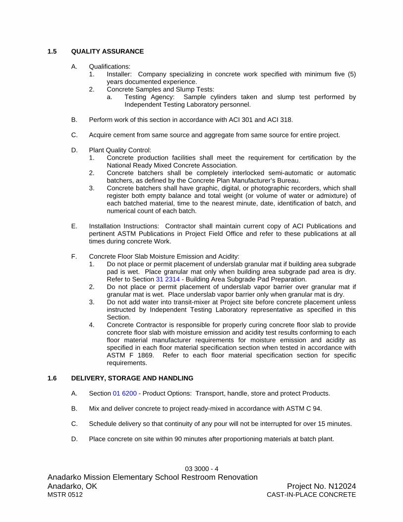
03 3000 - 4 Anadarko Mission Elementary School Restroom Renovation Anadarko, OK Project No. N12024 MSTR 0512 CAST-IN-PLACE CONCRETE
1.5 QUALITY ASSURANCE
A. Qualifications: 1. Installer: Company specializing in concrete work specified with minimum five (5)
years documented experience. 2. Concrete Samples and Slump Tests:
a. Testing Agency: Sample cylinders taken and slump test performed by Independent Testing Laboratory personnel.
B. Perform work of this section in accordance with ACI 301 and ACI 318.
C. Acquire cement from same source and aggregate from same source for entire project.
D. Plant Quality Control:
1. Concrete production facilities shall meet the requirement for certification by the National Ready Mixed Concrete Association.
2. Concrete batchers shall be completely interlocked semi-automatic or automatic batchers, as defined by the Concrete Plan Manufacturer’s Bureau.
3. Concrete batchers shall have graphic, digital, or photographic recorders, which shall register both empty balance and total weight (or volume of water or admixture) of each batched material, time to the nearest minute, date, identification of batch, and numerical count of each batch.
E. Installation Instructions: Contractor shall maintain current copy of ACI Publications and
pertinent ASTM Publications in Project Field Office and refer to these publications at all times during concrete Work.
F. Concrete Floor Slab Moisture Emission and Acidity:
1. Do not place or permit placement of underslab granular mat if building area subgrade pad is wet. Place granular mat only when building area subgrade pad area is dry. Refer to Section 31 2314 - Building Area Subgrade Pad Preparation.
2. Do not place or permit placement of underslab vapor barrier over granular mat if granular mat is wet. Place underslab vapor barrier only when granular mat is dry.
3. Do not add water into transit-mixer at Project site before concrete placement unless instructed by Independent Testing Laboratory representative as specified in this Section.
4. Concrete Contractor is responsible for properly curing concrete floor slab to provide concrete floor slab with moisture emission and acidity test results conforming to each floor material manufacturer requirements for moisture emission and acidity as specified in each floor material specification section when tested in accordance with ASTM F 1869. Refer to each floor material specification section for specific requirements.
1.6 DELIVERY, STORAGE AND HANDLING
A. Section 01 6200 - Product Options: Transport, handle, store and protect Products.
B. Mix and deliver concrete to project ready-mixed in accordance with ASTM C 94.
C. Schedule delivery so that continuity of any pour will not be interrupted for over 15 minutes.
D. Place concrete on site within 90 minutes after proportioning materials at batch plant.

03 3000 - 5 Anadarko Mission Elementary School Restroom Renovation Anadarko, OK Project No. N12024 MSTR 0512 CAST-IN-PLACE CONCRETE
1.7 PROJECT CONDITIONS
A. Hot Weather Concreting: 1. Follow ACI 301 and ACI 305R. 2. Provide retarding type admixture conforming to ASTM C 494, Type A or D in
accordance with manufacturer’s recommendations. 3. Maximum concrete temperature shall not exceed 95 degrees F at time of placement.
a. Obtain Architect approval for use of water reducer before using water reducer. b. With prior Architect approval, concrete with temperatures above 90 degrees F
shall be placed only if a high range water reducer (super plasticizer) is added to the mix as directed the Testing Laboratory to maintain the specified slump during placement.
B. Cold Weather Concreting: Protect concrete work from physical damage or reduced
strength which could be caused by frost, freezing actions, or low temperatures. 1. Follow ACI 301 and ACI 306R. 2. When ambient temperature at site is below 40 degrees F or is expected to fall to that
temperature within ensuing 24 hours, heat water and/or aggregate prior to adding to mix so that temperature of concrete will be between 55 degrees F and 85 degrees F at time of placement.
3. Maintain temperature of deposited concrete between 50 degrees F and 70 degrees F for minimum of seven days after placing.
4. Temperature Changes: Maintain changes in concrete temperature as uniformly as possible, but in no case exceed change of 5 degrees F per hour or 25 degrees F in any 24 hour period.
5. Do not use combustion heaters during first 48 hours without precautions to prevent exposure of concrete and workers to exhaust gases containing carbon dioxide and/or carbon monoxide.
C. Select admixture type (normal, retarder, or high early) best suited for concrete at the time
of placing. The use of calcium chloride is specifically prohibited. PART 2 PRODUCTS 2.1 REINFORCEMENT
A. Specified in Section 03 2000 - Concrete Reinforcement. 2.2 CONCRETE MATERIALS
A. Cement: ASTM C 150, Type I - Normal Portland type.
B. Fly Ash: ASTM C 618; Class C. 1. Maximum Percentage: 20 percent of cement content by weight. 2. Architectural Exposed Concrete: Fly ash not permitted.
C. Normal Weight Aggregates: ASTM C 33.
1. Fine: Clean, hard, durable, uncoated, natural sand, washed, free of silt, loam or clay. 2. Coarse: Hard, durable, uncoated gravel. Maximum size as follows:
a. Piers: 1-1/2 inches. b. All other Concrete: 1 inch.

03 3000 - 6 Anadarko Mission Elementary School Restroom Renovation Anadarko, OK Project No. N12024 MSTR 0512 CAST-IN-PLACE CONCRETE
3. Grading: ASTM C 136.
D. Water: Potable, clean and free from oil, acid and injurious amount of vegetable matter, alkalis and other impurities conforming to ASTM C 94.
2.4 ADMIXTURES
A. Air Entrainment: ASTM C 260.
B. Water Reducing: ASTM C 494, Type A or D. 1. Use in accordance with manufacturer’s published instructions and as determined by
Testing Laboratory. 2. Admixture shall not discolor concrete or affect appearance of concrete. 3. High-range Type F may be used.
C. Calcium Chloride: Not permitted.
2.5 CONCRETE ACCESSORIES
A. Bonding Agent: ASTM C 1059, Type II acrylic non-redispersable type.
B. Non-Shrink Grout: ASTM C 1107; premixed compound consisting of non-metallic aggregate, cement, water reducing and plasticizing agents. 1. Minimum Compressive Strength at 7 Days: 5000 psi. 2. Minimum Compressive Strength at 28 Days: 7500 psi.
C. Vapor Barrier
D. Epoxy Adhesive: ASTM C 881, two-component material suitable for use on dry or damp surfaces. Provide material type, grade, and class to suit Project requirements.
2.6 JOINT DEVICES AND MATERIALS
A. Joint Filler: Nonextruding, resilient asphalt impregnated fiberboard or felt, complying with ASTM D 1751, thickness as indicated on Drawings and width/depth as indicated.
B. Construction Joint Devices: Steel slab construction joints not permitted.
C. Sealant and Primer: Specified in Section 07 9000 - Joint Sealers.
2.7 CONCRETE MIX DESIGN
A. Design Criteria: 1. Design concrete mixes in accordance with ACI 318. 2. For each concrete mix type proposed.
B. Proportioning Normal Weight Concrete: Proportions of cement, aggregate, and water to
attain required plasticity and compressive strength shall be in accordance with ACI 318. 1. Mix designs furnished by concrete supplier, and accompanied by test data showing
an acceptable strength history meeting requirements of Method 2 as specified in Section 3.8 of ACI 301. a. Temperature of concrete in test data shall be within 5 degrees F of maximum
temperature specified for this project.

03 3000 - 7 Anadarko Mission Elementary School Restroom Renovation Anadarko, OK Project No. N12024 MSTR 0512 CAST-IN-PLACE CONCRETE
b. Strengths indicated in test data shall be in accordance with ACI 318, paragraph 4.3.
c. Specified strength of concrete used in supporting test data shall vary no more than 500 psi plus or minus from that specified for this Project.
2. Testing Laboratory: Keep strength history record of all concrete for duration of Project.
C. Concrete Strength: Establish required average strength for each type of concrete on basis
of field experience or trial mixtures, as specified in ACI 301.
D. Admixtures: Add acceptable admixtures as recommended in ACI 211.1 at rates recommended by manufacturer.
E. Normal Weight Concrete:
1. Compressive Strength, when tested in accordance with ASTM C 39 at 28 days: a. Building Slabs on Grade: 3000 psi.
2. Slump:
a. Building Slabs: 3 to 4 inches. 2.8 MIXING
A. Use transit-mixed concrete conforming to requirements of ASTM C 94 and ACI 304. Do not use concrete mixed at Project Site. Do not transport concrete or use concrete in any case after maximum of 90 minutes elapsed after introduction of water into mixer. 1. Temperatures Between 85 and 90 Degrees F: When air temperature is between 85
degrees F and 90 degrees F, reduce mixing and delivery time to maximum 75 minutes.
2. Temperatures Above 90 Degrees F: When air temperature is above 90 degrees F, reduce mixing and delivery time to maximum 60 minutes.
B. Indiscriminate addition of water to increase slump of concrete not permitted.
1. Add water only at direction of Testing Laboratory and/or Architect. 2. Do not add water that increases water cement ratio of concrete in excess of water
cement ratio indicated on approved mix design. 3. At direction of Testing Laboratory addition of a high range water reducing admixture
may be used to retemper concrete with specific approval of Architect. Do not use without approval of Architect.
C. Agency supplying transit-mixed concrete shall have plant of sufficient capacity and
adequate transportation facilities, to assure continuous delivery at rate required. Frequency of deliveries to Project Site shall be sufficient to provide for placing concrete continuously throughout any one (1) pour.
PART 3 EXECUTION 3.1 EXAMINATION
A. Section 01 7300 - Execution: Verification of existing conditions before starting work.
B. Verification of Conditions: Verify that field measurements, surfaces, substrates and conditions are as required, and ready to receive Work.

03 3000 - 8 Anadarko Mission Elementary School Restroom Renovation Anadarko, OK Project No. N12024 MSTR 0512 CAST-IN-PLACE CONCRETE
1. Verify lines, levels, and dimensions before proceeding with work of this section. 2. Verify that screeding equipment is calibrated to provide concrete slab to specified
flatness and levelness requirements.
C. Report in writing to Architect prevailing conditions that will adversely affect satisfactory execution of the Work of this Section. Do not proceed with Work until unsatisfactory conditions have been corrected.
D. By beginning Work, Contractor accepts conditions and assumes responsibility for
correcting unsuitable conditions encountered at no additional cost to the Owner. Costs for correcting unsuitable conditions will be at Contractor’s expense. 1. If Architect or Architect’s Consultants are required to perform additional services
caused by Contractor having to correct unsuitable conditions: a. Architect will invoice Owner for additional services by the Architect or
Architect’s Consultants. b. Contractor will pay for Architect’s or Architect’s Consultants additional services
by deductive change order. c. Change order will be issued deducting the additional services amount from the
Contract Sum. 3.2 PREPARATION
A. Verify that forms are clean and free of rust before applying release agent.
B. Coordinate placement of joint devices with erection of concrete formwork and placement of form accessories.
C. Prepare previously placed concrete by cleaning with steel brush and applying bonding
agent in accordance with manufacturer's instructions.
D. In locations where new concrete is doweled to existing work, drill holes in existing concrete, insert steel dowels and pack solid with non-shrink grout.
E. Granular Fill Mat Placement: Place granular base over building area subgrade pad under
building floor slab-on-grade. Refer to Section 31 2324 - Fill and Backfill for placement of granular mat fill material and installation requirements. 1. Vapor Barrier: Place vapor barrier over granular mat fill.
F. Convey concrete from mixer to place of final deposit by methods that prevent separation or loss of ingredients. 1. Concrete to be conveyed by pumping shall be submitted to Testing Laboratory for
evaluation for each class of concrete taken at discharge end of pumping equipment.
G. Equipment for chuting, pumping, and pneumatically conveying concrete shall be of such size and design to ensure practically continuous flow of concrete at delivery end without separation of materials. 1. Use of gravity-flow or aluminum chutes or conveyors for transporting concrete
horizontally not permitted.
3.3 ADVANCE NOTIFICATION TO ARCHITECT AND ENGINEER

03 3000 - 9 Anadarko Mission Elementary School Restroom Renovation Anadarko, OK Project No. N12024 MSTR 0512 CAST-IN-PLACE CONCRETE
A. Architect shall observe excavations, reinforcing steel and preparations for placing concrete before start of concrete placement.
B. Contractor shall notify Architect and Engineer 36-hours, and no later than 24-hours, before
start of concrete placement operations to provide Architect sufficient time to travel to Project Site and observe Contractor preparations for concrete placement. 1. Leaving only a voicemail message or sending only an e-mail or fax without receipt of
confirmation from Architect not permitted. 2. Placing concrete without notification of Architect and Engineer will make Contractor
liable for any additional testing or removal and replacement as directed by Architect.
C. Contractor notification shall be to an actual person in Architect’s office with acknowledgement of notification receipt by Architect.
3.4 ADVANCE NOTIFICATION TO INDEPENDENT TESTING LABORATORY
A. Contractor shall notify independent testing laboratory minimum 36-hours, and no later than 24 hours, before start of concrete placement operations.
3.5 PLACING CONCRETE
A. Independent testing laboratory ACI Concrete Laboratory Technician - Grade 1 shall be at Project Site, ready for start of concrete placement, observations, taking samples and performing specified tests before arrival of first concrete transit-mix truck and start of concrete placement.
B. Project Field Superintendent shall measure air temperature before ordering concrete to
determine if hot weather or cold weather concreting measures are required. Record air temperature in Superintendent's Daily Log.
C. Place concrete when weather is dry. Concrete placement not permitted during rain or
when footing excavation, vapor barrier, granular mat or subgrade are wet. After rain, allow footings, vapor barrier, granular mar or subgrade to dry thoroughly before placing concrete.
D. Footing excavation shall be dry. Concrete placement not permitted if footing excavation is
wet or has standing water.
E. Place concrete in accordance with ACI 304R.
F. Place concrete for floor slabs in accordance with ACI 302.2R.
G. Ensure vapor barrier, reinforcement, inserts, waterstops, embedded parts, and formed construction joint devices will not be disturbed during concrete placement.
H. Place concrete in uniform layer, approximately horizontal, and not more than 18 inches
deep, exercising care to avoid vertical joints or inclined planes. 1. Piling up of concrete in forms in a manner to cause separation or loss of any of its
ingredients not permitted. 2. Concrete which has partially set or hardened shall not, under any circumstances, be
deposited in Work.
I. Placing Concrete in Forms: Place concrete in forms as nearly in its final position as is practical to avoid rehandling. Deposit concrete in horizontal layers maximum 24 inches

03 3000 - 10 Anadarko Mission Elementary School Restroom Renovation Anadarko, OK Project No. N12024 MSTR 0512 CAST-IN-PLACE CONCRETE
and in a manner to avoid inclined construction joints. Exercise special care to prevent splashing forms or reinforcement with concrete. 1. Remove any hardened or partially hardened concrete which has accumulated on the
forms or reinforcement before the work proceeds. 2. Do not place concrete on previously deposited concrete which has hardened
sufficiently to cause the formation of seams or planes of weakness within the respective member of section, except as hereinafter specified.
3. Consolidate placed concrete by mechanical vibrating equipment.
J. Placing Concrete Slabs: Place and consolidate concrete slabs in continuous operation, within limits of construction joints, until completion of panel or section placement. 1. Consolidate concrete during placement operations so that concrete is thoroughly
worked around reinforcement, other embedded items and into corners. 2. Bring slab surfaces to correct level with straightedge and strike off. Use bull floats or
derbies to smooth surface free of humps or hollows. Do not disturb slab surfaces before beginning finishing operations.
3. Maintain reinforcing in proper position on chairs during concrete placement.
K. Do not permit concrete to drop freely any distance greater than five (5) feet. Where longer drops are necessary, use a chute, tremie, or other acceptable conveyance to assist the concrete into place without separation. Do not pour directly into any excavations where water is standing.
L. Vibration: As soon as concrete is deposited, thoroughly agitate same by means of
mechanical vibrators and suitable hand tools, so manipulated as to work the mixture well into all parts and corners of the forms, and entirely around the reinforcement and inserts. 1. Mechanical vibrators shall maintain frequencies in accordance with the
recommendations of ACI 309, Table 5.1.4, and shall be operated by competent workmen.
2. Over vibrating and use of vibrators to transport concrete within forms shall not be allowed.
3. Keep spare vibrator on job site during concrete placing operations.
M. Bonding: Before depositing any new concrete on or against previously deposited concrete which has partially or entirely set, the surface of the latter shall be thoroughly roughened and cleaned of all foreign matter, scum and laitance. Coat surface of previously deposited concrete with a bonding agent per manufacturer’s direction.
N. Separate slabs on grade from vertical surfaces with joint filler.
O. Place joint filler in floor slab pattern placement sequence. Set top to required elevations.
Secure to resist movement by wet concrete.
P. Extend joint filler from bottom of slab to within 1/2 inch of finished slab surface.
Q. Install joint devices in accordance with manufacturer's instructions.
R. Locate construction joints in coordination with floor slab pattern placement sequence. Provide keyways minimum 1-1/2 inches deep in walls and slabs and between walls and footings. 1. Place construction joints perpendicular to main reinforcement. Continue
reinforcement across construction joints, unless indicated otherwise.

03 3000 - 11 Anadarko Mission Elementary School Restroom Renovation Anadarko, OK Project No. N12024 MSTR 0512 CAST-IN-PLACE CONCRETE
2. Except as otherwise specifically indicated on Structural Drawings, each concrete member shall be considered as a single unit of operation, and all concrete for the same shall be placed continuously in order that such unit will be monolithic in construction.
3. Should construction joints prove to be absolutely unavoidable, same shall be located at or near the midpoints of spans.
4. Additional construction joints shall not be made under any circumstances without prior review by the Architect and Structural Engineer.
5. Use bonding agent on existing concrete surfaces joined with fresh concrete.
S. Saw cut joints within 8 hours after placing. Use 3/16 inch thick blade, cut into 1/4 depth of slab thickness.
T. Screed floors level, maintaining specified surface Flatness and Levelness.
U. Fill in holes and openings left in concrete structures for passage of Work by other trades,
unless otherwise shown or directed, after Work of other trades is in place. Mix, place, and cure concrete as specified to blend with in-place construction.
V. Provide monolithic finish to interior curbs by stripping forms while concrete is green and by
steel-troweling surfaces to a hard, dense finish with corners, intersections, and terminations slightly rounded.
W. Provide machine and equipment bases and foundations as indicated on Drawings. Set
anchor bolts for machines and equipment to template at correct elevations, complying with diagrams or templates of manufacturer furnishing machines and equipment.
X. Provide concrete fill for steel pan stair treads, landings and associated items. Cast-in
safety inserts and accessories as indicated on Drawings. Screed, tamp and trowel-finish concrete surfaces.
Y. Protect all freshly placed concrete from washing by rain, flowing water etc. Do not allow
the concrete to dry out from the time it is deposited in the forms until expiration of curing period.
Z. Maintain records of concrete placement. Record date, location, quantity, air temperature,
and test samples taken. slabs as specified in Section 03 3906 - Moisture Emission and Acidity Control System.
3.6 FIELD QUALITY CONTROL
A. Section 01 4500 - Quality Control: Contractor Quality Control Representative shall perform contractor quality control inspections. 1. Inspect concrete placement, concrete pumping, leveling and screeding operations. 2. Check floor slab for compliance with specified Floor Flatness and Floor Levelness. 3. Document preparatory, initial and follow-up inspection in Contractor’s Test and
Inspection Reports. 4. Test and Inspection Reports shall be available to Architect upon request.
B. Section 01 4523 - Testing and Inspection Services:
1. Tests: Perform the following tests.

03 3000 - 12 Anadarko Mission Elementary School Restroom Renovation Anadarko, OK Project No. N12024 MSTR 0512 CAST-IN-PLACE CONCRETE
a. Compressive Strength Tests: Perform minimum one (1) test for each 100 cubic yards or fraction thereof, of each mix design of concrete placed in any 1 day.
3.7 DEFECTIVE CONCRETE
A. Defective Concrete: Concrete not conforming to required lines, details, dimensions, tolerances or specified requirements.
B. Repair or replacement of defective concrete will be determined by the Architect. The cost
of additional testing shall be borne by Contractor when defective concrete is identified.
C. Do not patch, fill, touch-up, repair, or replace exposed concrete except upon express direction of Architect for each individual area.
D. Failed Strength Tests: If compressive strength tests indicate results below specified
strength, Architect may require any or all of the following corrective measures be performed at Contractor's expense. Architect will determine extent of concrete removal if required. 1. Change concrete mix. 2. Core test in conformance with ASTM C 42. 3. Load test on portion or portions of structure where test cylinders indicate concrete is
below specified strength. Load testing performed in conformance with ACI 318. 4. Remove and replace concrete below specified strength.
END OF SECTION

04 2111 - 1 Anadarko Mission Elementary School Restroom Renovation Anadarko, OK Project No. N12024MSTR 0710 BRICK VENEER
SECTION 04 2111 BWA MSTR 0710 BRICK VENEER PART 1 GENERAL 1.1 SUMMARY
A. Section Includes: 1. Facebrick units. 2. Mortar and flashings. 3. Reinforcement, anchorage, and accessories.
B. Related Documents:
1. The Contract Documents, as defined in Document 00 7213 - General Conditions and modifications thereto, apply to the Work of this Section. Additional requirements and information necessary to complete the Work of this Section may be found in other documents.
C. Related Sections:
1. Section 07 2113 - Board Insulation: Insulation installed in veneer air space. 2. Section 07 9000 - Joint Sealers: Rod and sealant at control joints.
1.2 REFERENCES
A. American Society for Testing and Materials (ASTM): 1. ASTM C 652 - Standard Specification for Hollow Brick (Hollow Masonry Units Made
From Clay Shale). 2. ASTM C 270 - Standard Specification for Mortar for Unit Masonry.
B. Brick Industry Association (BIA):
1. BIA TN18A - Technical Notes; Design and Detailing of Movement Joints.
C. International Masonry Industry All-Weather Council (IMIAWC): 1. IMIWAC (CW) - Recommended Practices & Guide Specifications for Cold Weather
Masonry Construction. 2. IMIWAC (HW) - Recommended Practices & Guide Specifications for Hot Weather
Masonry Construction. 1.3 SUBMITTALS
A. Section 01 3300 - Submittal Procedures: Requirements for submittals.
B. Product Data: Provide data for masonry units, mortar, wall ties, thru-wall flashing, termination bar, drainage mat and weep hole inserts.
C. Samples for Selection: Submit complete set of manufacturer’s color samples for brick
veneer and mortar to illustrate color, texture and extremes of color range for Architect initial selection.
1.4 QUALITY ASSURANCE

04 2111 - 2 Anadarko Mission Elementary School Restroom Renovation Anadarko, OK Project No. N12024MSTR 0710 BRICK VENEER
A. Installer Qualifications: Company specializing in manufacturing the Products specified in this section with minimum five (5) years documented experience.
1.5 DELIVERY, STORAGE, AND HANDLING
A. Section 01 6200 - Product Options: Transport, handle, store and protect Products.
B. Deliver materials in manufacturer’s original, unopened, undamaged containers with identification labels intact.
C. Package brick units and protect from staining or damage during shipping and storage.
D. Accept Products on site in manufacturer’s packaging. Inspect for damage. Return
damaged Products and replace with undamaged Products.
E. Project Field Superintendent shall inspect Products immediately upon delivery to Project Site, determine Product conformance with specified requirements and reject Products not complying with specifications. Project Field Superintendent shall direct that non-complying Products be removed from Project Site immediately.
F. Store materials protected from exposure to harmful weather conditions and at temperature
and humidity conditions recommended by manufacturer.
G. Provide itemized list of product to support bill of lading. 1.6 PROJECT CONDITIONS
A. Environmental Requirements: 1. Cold Weather Requirements: Comply with recommendations of IMIAWC (CW). 2. Hot Weather Requirements: Comply with recommendation of IMIAWC (HW).
1.7 COORDINATION
A: Section 01 3100 - Project Management and Coordination: Coordination of Work with other trades in advance and make provisions for the installation of their work to avoid cutting and patching.
B. Coordinate brick veneer work with wall mounted lighting fixtures, plumbing items, openings
and chases for heating ducts, plumbing pipes and electrical conduit. Build into Work as construction progresses.
C. Coordinate installation of wall ties in concrete unit masonry and installation of rigid
insulation in cavity between block and brick.
D Provide for installation of bolts, toggles, flashing, beams, anchors, hangers, nailing strips, wall plugs and frames as required for support of structure and miscellaneous appliances.
PART 2 PRODUCTS 2.1 BRICK UNITS
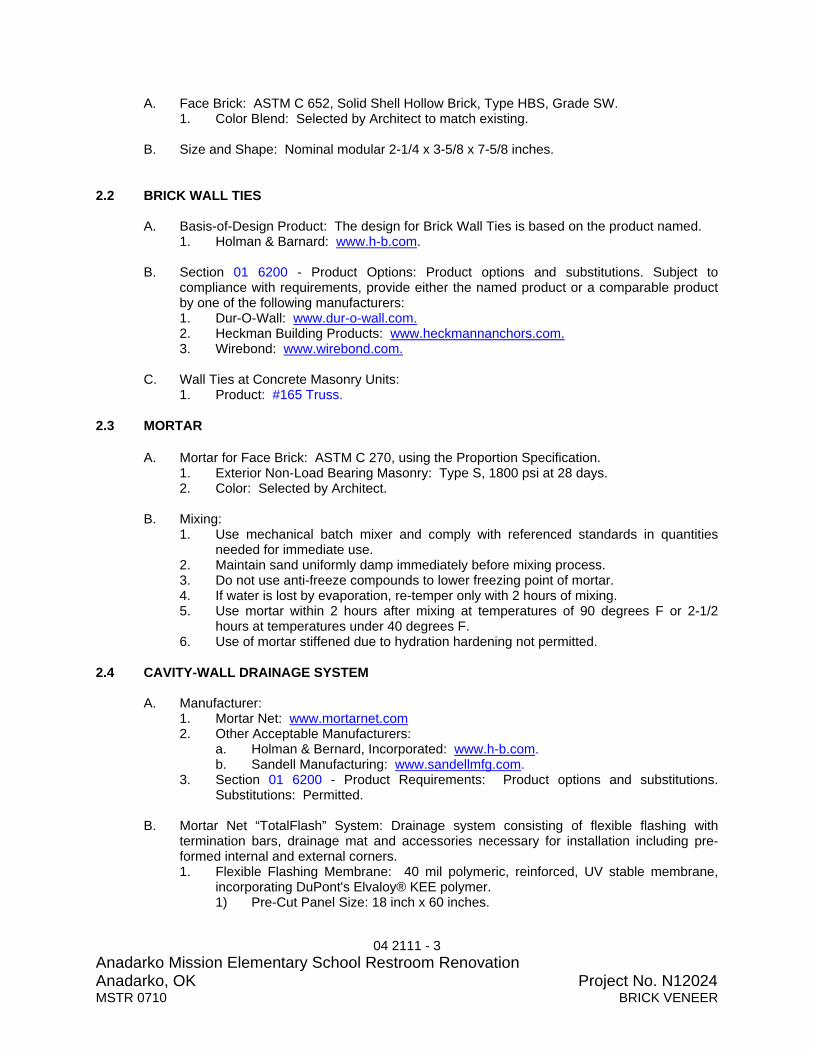
04 2111 - 3 Anadarko Mission Elementary School Restroom Renovation Anadarko, OK Project No. N12024MSTR 0710 BRICK VENEER
A. Face Brick: ASTM C 652, Solid Shell Hollow Brick, Type HBS, Grade SW. 1. Color Blend: Selected by Architect to match existing.
B. Size and Shape: Nominal modular 2-1/4 x 3-5/8 x 7-5/8 inches.
2.2 BRICK WALL TIES
A. Basis-of-Design Product: The design for Brick Wall Ties is based on the product named. 1. Holman & Barnard: www.h-b.com.
B. Section 01 6200 - Product Options: Product options and substitutions. Subject to
compliance with requirements, provide either the named product or a comparable product by one of the following manufacturers: 1. Dur-O-Wall: www.dur-o-wall.com. 2. Heckman Building Products: www.heckmannanchors.com. 3. Wirebond: www.wirebond.com.
C. Wall Ties at Concrete Masonry Units:
1. Product: #165 Truss. 2.3 MORTAR
A. Mortar for Face Brick: ASTM C 270, using the Proportion Specification. 1. Exterior Non-Load Bearing Masonry: Type S, 1800 psi at 28 days. 2. Color: Selected by Architect.
B. Mixing:
1. Use mechanical batch mixer and comply with referenced standards in quantities needed for immediate use.
2. Maintain sand uniformly damp immediately before mixing process. 3. Do not use anti-freeze compounds to lower freezing point of mortar. 4. If water is lost by evaporation, re-temper only with 2 hours of mixing. 5. Use mortar within 2 hours after mixing at temperatures of 90 degrees F or 2-1/2
hours at temperatures under 40 degrees F. 6. Use of mortar stiffened due to hydration hardening not permitted.
2.4 CAVITY-WALL DRAINAGE SYSTEM
A. Manufacturer: 1. Mortar Net: www.mortarnet.com 2. Other Acceptable Manufacturers:
a. Holman & Bernard, Incorporated: www.h-b.com. b. Sandell Manufacturing: www.sandellmfg.com.
3. Section 01 6200 - Product Requirements: Product options and substitutions. Substitutions: Permitted.
B. Mortar Net “TotalFlash” System: Drainage system consisting of flexible flashing with
termination bars, drainage mat and accessories necessary for installation including pre-formed internal and external corners. 1. Flexible Flashing Membrane: 40 mil polymeric, reinforced, UV stable membrane,
incorporating DuPont's Elvaloy® KEE polymer. 1) Pre-Cut Panel Size: 18 inch x 60 inches.

04 2111 - 4 Anadarko Mission Elementary School Restroom Renovation Anadarko, OK Project No. N12024MSTR 0710 BRICK VENEER
2. Drainage Mat: Recycled polyester material impregnated with UV protection, mold and flame retardant. Woven mesh attached to flexible flashing designed to allow moisture to migrate to the integrated weep tabs. 1) 3/8 inch x 10 inches x 60 inches long.
3. Adhesive: No slump, moisture cure, multi purpose, structural sealant provided with system for lapping flash sections.
4. Termination Bar: Pre-attached to flashing membrane, termination bar designed to fasten flashing system to the substrate or fit into mortar joint. High strength plastic, 60 inches long with pre-drilled holes at 6 inches on-center for attachment.
5 Screws: Provide #14 self-tapping hex head screws designed to allow attachment to substrate.
PART 3 EXECUTION 3.1 EXAMINATION
A. Section 01 7300 - Execution: Verification of existing conditions before starting work.
B. Verification of Conditions: Verify that field measurements, surfaces, substrates and conditions are as required, and ready to receive Work. 1. Verify that field conditions are acceptable and are ready to receive masonry. 2. Verify that related items provided under other sections are properly sized and
located. 3. Verify that built-in items are in proper location, and ready for roughing into masonry
work.
C. Report in writing to Architect prevailing conditions that will adversely affect satisfactory execution of the Work of this Section. Do not proceed with Work until unsatisfactory conditions have been corrected.
D. By beginning Work, Contractor accepts conditions and assumes responsibility for
correcting unsuitable conditions encountered at no additional cost to the Owner. 3.2 PREPARATION
A. Direct and coordinate placement of metal anchors supplied to other sections.
B. Provide temporary bracing during installation of masonry work. Maintain in place until building structure provides permanent bracing.
3.3 COURSING
A. Establish lines, levels, and coursing indicated. Protect from displacement.
B. Maintain masonry courses to uniform dimension. Form vertical and horizontal joints of uniform thickness.
C. Bond: Running.
D. Coursing: Three units and three mortar joints to equal 8 inches.
E. Mortar Joints: match existing.
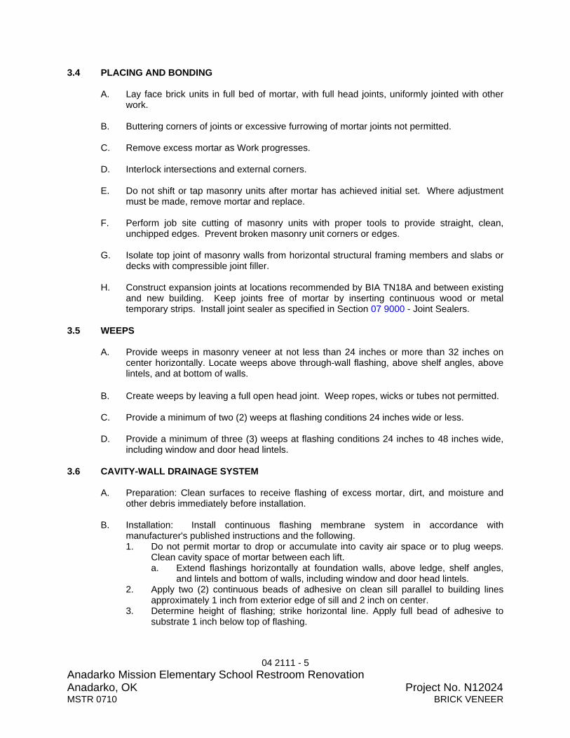
04 2111 - 5 Anadarko Mission Elementary School Restroom Renovation Anadarko, OK Project No. N12024MSTR 0710 BRICK VENEER
3.4 PLACING AND BONDING
A. Lay face brick units in full bed of mortar, with full head joints, uniformly jointed with other work.
B. Buttering corners of joints or excessive furrowing of mortar joints not permitted.
C. Remove excess mortar as Work progresses.
D. Interlock intersections and external corners.
E. Do not shift or tap masonry units after mortar has achieved initial set. Where adjustment
must be made, remove mortar and replace.
F. Perform job site cutting of masonry units with proper tools to provide straight, clean, unchipped edges. Prevent broken masonry unit corners or edges.
G. Isolate top joint of masonry walls from horizontal structural framing members and slabs or
decks with compressible joint filler.
H. Construct expansion joints at locations recommended by BIA TN18A and between existing and new building. Keep joints free of mortar by inserting continuous wood or metal temporary strips. Install joint sealer as specified in Section 07 9000 - Joint Sealers.
3.5 WEEPS
A. Provide weeps in masonry veneer at not less than 24 inches or more than 32 inches on center horizontally. Locate weeps above through-wall flashing, above shelf angles, above lintels, and at bottom of walls.
B. Create weeps by leaving a full open head joint. Weep ropes, wicks or tubes not permitted.
C. Provide a minimum of two (2) weeps at flashing conditions 24 inches wide or less.
D. Provide a minimum of three (3) weeps at flashing conditions 24 inches to 48 inches wide,
including window and door head lintels. 3.6 CAVITY-WALL DRAINAGE SYSTEM
A. Preparation: Clean surfaces to receive flashing of excess mortar, dirt, and moisture and other debris immediately before installation.
B. Installation: Install continuous flashing membrane system in accordance with
manufacturer's published instructions and the following. 1. Do not permit mortar to drop or accumulate into cavity air space or to plug weeps.
Clean cavity space of mortar between each lift. a. Extend flashings horizontally at foundation walls, above ledge, shelf angles,
and lintels and bottom of walls, including window and door head lintels. 2. Apply two (2) continuous beads of adhesive on clean sill parallel to building lines
approximately 1 inch from exterior edge of sill and 2 inch on center. 3. Determine height of flashing; strike horizontal line. Apply full bead of adhesive to
substrate 1 inch below top of flashing.

04 2111 - 6 Anadarko Mission Elementary School Restroom Renovation Anadarko, OK Project No. N12024MSTR 0710 BRICK VENEER
4. Set flashing in sill adhesive and turn flashing up minimum 8 inches. Roll flashing and termination bar assembly into sill adhesive and up wall; securing assembly with screws provided with System.
5. Apply full bead of adhesive to top of termination bar. 6. Lap end joints minimum 6 inches and seal watertight using adhesive provided.
a. Turn flashing, fold, and seal at corners, bends, and interruptions.
C. Termination of System: 1. Terminate vertical membrane with continuous termination bar secured at 6 inches
on-center. 2. Prepare lap joints as directed by manufacturer. Apply adhesive and lap flexible
flashing a minimum of 6 inches.
D. Inspection: 1. Make sure flexible flashing is installed in continuous manner with no voids, or
punches. Repair punches prior to starting masonry Work. 2. Edge dams at horizontal termination of flashing shall be well defined and secured to
substrate. 3. Drainage mat weep tabs shall be laid flat.
3.7 BRICK WALL TIES
A. Wall Ties at Concrete Masonry Units: 1. Embed truss type wall ties in concrete unit masonry for bonding veneer using one (1)
tie for each 2.67 square feet of wall area as follows: a. Vertically: Maximum 16 inch on center b. Horizontally: Maximum 24 inch on center
2. Place at maximum 3 inches on center each way around perimeter of openings, within 12 inches of openings
3.8 CUTTING AND FITTING
A. Cut and fit for conduit, sleeves and inserts. Coordinate with other sections of work to provide correct size, shape, and location.
B. Obtain approval prior to cutting or fitting masonry work not indicated or where appearance
or strength of masonry work may be impaired. 3.8 FIELD QUALITY CONTROL
A. Section 01 4500 - Quality Control: Perform contractor quality control inspections. 1. Inspect brick veneer installation, wall ties, brick type and blend, joints, weeps, inserts,
built-in items and seal around penetrations. 2. Inspect thru-wall flashing, laps, corners, intersections and terminations for watertight
installation. 3. Document preparatory, initial and follow-up inspection in Contractor’s Test and
Inspection Reports. 4. Test and Inspection Reports shall be available to Architect upon request.
B. Correct deficiencies in products and installation found not to be in compliance with Contract
Documents. 3.10 CLEANING

04 2111 - 7 Anadarko Mission Elementary School Restroom Renovation Anadarko, OK Project No. N12024MSTR 0710 BRICK VENEER
A. Clean work.
B. Remove excess mortar and mortar smears.
C. Replace defective mortar. Match adjacent work.
D. Clean soiled surfaces with cleaning solution.
E. Use non-metallic tools in cleaning operations.
3.12 PROTECTION OF FINISHED WORK
A. Protect finished Work.
B. Without damaging completed work, provide protective boards at exposed external corners which may be damaged by construction activities.
END OF SECTION

07 2706 - 1 Anadarko Mission Elementary School Restroom Renovation Anadarko, OK Project No. N12024 MSTR 1110 WEATHER RESISTANT BARRIER
SECTION 07 2706 BWA MSTR 1110 WEATHER RESISTANT BARRIER PART 1 GENERAL 1.1 SUMMARY
A. Section Includes: 1. Vapor retarder and air barrier for exterior wall assemblies.
B. Related Documents:
1. The Contract Documents, as defined in Document 00 7213 - General Conditions and modifications thereto, apply to the Work of this Section. Additional requirements and information necessary to complete the Work of this Section may be found in other documents.
C. Related Sections:
1. Section 09 2815 - Gypsum Sheathing: Exterior gypsum wall sheathing. 1.2 REFERENCES
A. American Association of Textile Chemists and Colorists (AATCC): 1. AATCC Test Method 127 - Water Resistance: Hydrostatic Pressure Test.
B. American Society for Testing and Materials (ASTM):
1. ASTM C 920 - Standard Specification for Elastomeric Joint Sealants. 2. ASTM E 96 - Standard Test Methods for Water Vapor Transmission of Materials. 3. ASTM E 1677 - Standard Specification for an Air Retarder (AR) Material or System
for Low-Rise Framed Building Walls. 1.3 DEFINITIONS
A. Air Barrier: Continuous network of materials and joints providing air tightness, with adequate strength and stiffness to not deflect excessively under air pressure differences, to which it will be subjected in service.
B. Vapor Retarder: Material that resists water vapor diffusion through it.
1.4 SUBMITTALS
A. Section 01 3300 - Submittal Procedures: Requirements for submittals.
B. Product Data: Provide manufacturer’s data indicating material, thickness and performance characteristics. 1. Weather resistant barrier sheet. 2. Sealing tape. 3. Sealant.
1.5 QUALITY ASSURANCE

07 2706 - 2 Anadarko Mission Elementary School Restroom Renovation Anadarko, OK Project No. N12024 MSTR 1110 WEATHER RESISTANT BARRIER
A. Installer Qualifications: Company specializing in performing Work of this Section with minimum five (5) years documented experience.
B. Single Source Responsibility: Provide all weather-resistant barrier components from a
single source from one manufacturer.
C. Regulatory Requirements: Conform to the requirements contained in National Evaluation Service Report NER-642.
1.6 DELIVERY, STORAGE, AND HANDLING
A. Section 01 6200 - Product Options: Transport, handle, store, and protect Products.
B. Deliver materials in manufacturer’s original, unopened, undamaged containers with identification labels intact.
C. Deliver Material Safety Data Sheet (MSDS) for each material to Project Field
Superintendent for Contractor Records.
D. Accept Products on site in manufacturer’s packaging. Inspect for damage. Return damaged Products and replace with undamaged Products.
E. Project Field Superintendent shall inspect Products immediately upon delivery to Project
Site, determine Product conformance with specified requirements and reject Products not complying with specifications. Project Field Superintendent shall direct that non-complying Products be removed from Project Site immediately.
F. Protect materials from rain and physical damage. Provide cover on top and all sides.
Allow for adequate ventilation.
G. Store products in dry area away from high heat, flames or sparks. 1.7 SEQUENCING
A. Schedule installation of weather-resistant barrier with installation of windows, doors and flashings.
B. Do not install weather-resistant barrier until items penetrating it are in place.
C. Weather-resistant barrier must be covered with finish materials within 4 months of
installation. PART 2 PRODUCTS 2.1 MANUFACTURERS
A. Basis-of-Design Product: The design for Weather Resistant Barrier is based on the
product named. 1. DuPont Company: www2.dupont.com/Tyvek/en_US
B. Section 01 6200 - Product Options: Product options and substitutions. Substitutions:
Permitted.

07 2706 - 3 Anadarko Mission Elementary School Restroom Renovation Anadarko, OK Project No. N12024 MSTR 1110 WEATHER RESISTANT BARRIER
2.2 WEATHER RESISTANT BARRIER
A. Product: Tyvek Commercial Wrap.
B. Description: Flash spun-bonded olefin, non-woven, non-perforated secondary weather resistant barrier.
C. Physical Properties:
1. Classification: ASTM E 1677, Type I. 2. Water Vapor Transmission: Greater than 28 perms when tested in accordance with
ASTM E 96, Method B. 3. Water Penetration Resistance: Minimum 280 cm when tested in accordance with
AATCC Test Method 127. 2.3 ACCESSORIES
A. Sealing Tape: DuPont Tyvek Tape.
B. Fasteners to Steel Frame Construction: Dupont Tyvek Wrap Cap Screws, 1-5/8 inch rust resistant with 2 inch diameter plastic cap.
C. Fasteners to Wall Sheathing: Polyurethane or elastomeric adhesives.
PART 3 EXECUTION 3.1 EXAMINATION
A. Section 01 7300 - Execution: Verification of existing conditions before starting work.
B. Verification of Conditions: Verify that field measurements, surfaces, substrates and conditions are as required, and ready to receive Work.
C. Report in writing to Architect prevailing conditions that will adversely affect satisfactory
execution of the Work of this Section. Do not proceed with Work until unsatisfactory conditions have been corrected.
D. By beginning Work, Contractor accepts conditions and assumes responsibility for
correcting unsuitable conditions encountered at no additional cost to the Owner. 3.2 INSTALLATION - WALLS
A. Install barrier over exterior side of exterior wall sheathing in accordance with manufacturer’s published instructions.
B. Install barrier after sheathing is installed and before windows and doors are installed.
Install lower level barrier before upper layers to ensure proper shingling of layers.
C. Attach barrier to framing and sheathing with fasteners spaced 12 inches to 18 inches on vertical stud line
D. Overlap barrier at corners of building minimum 12 inches.

07 2706 - 4 Anadarko Mission Elementary School Restroom Renovation Anadarko, OK Project No. N12024 MSTR 1110 WEATHER RESISTANT BARRIER
E. Overlap barrier vertical seams minimum 6 inches.
F. Install barrier plum and level with foundation; unroll extending barrier over window and door openings.
G. Tape all remaining horizontal seams and seal joints and penetrations through weather-
resistant barriers with tape before installation of finish materials. Tape all remaining vertical breaks or overlaps. Install strips of cut weather-resistive barrier material as necessary to provide barrier to barrier taped joints. 1. Tape and seal around masonry ties to create an air and moisture barrier seal.
I. Do not tape edges of weather-resistive barrier material to sheathing, insulation or
substrate. 3.3 INSTALLATION - WINDOWS AND DOORS
A. Coordinate installation of weather-resistive barrier with installation of flashings at windows and doors. Install flashing in accordance with flashing manufacturer’s published instructions.
B. Install barrier before installation of windows and doors.
C. Windows:
1. Prepare each window rough opening by cutting a modified “I” pattern in weather-resistive barrier.
2. Horizontally cut weather-restive barrier along bottom of header. Vertically cut weather-resistive barrier down center of window opening from top of window opening down to 2/3 to bottom of window opening.
3. Diagonally cut weather-resistant barrier from bottom of vertical cut to left and right bottom corners of opening.
4. Fold side and bottom flaps into window opening and fasten at 6 inches on center. Trim excess.
5. Cut weather-resistive barrier at 45 degree angles, creating flap, at top corners of window frame. Overlap flap at window flange and head flashing after window installation. Tape 45 degree seams and horizontal seams along window head using 2 inch or 3 inch sealing tape.
D. Doors:
1. Prepare each rough door opening by cutting standard “I” pattern in weather-resistive barrier.
2. Horizontally cut weather-resistive barrier along bottom of door frame header and along top of sill.
3. Vertically cut weather-resistive barrier down center of door openings from top of door opening to bottom of door opening.
4. Fold side flaps inside around door openings and fasten at 6 inches on center. Trim excess.
5. Cut weather-resistive barrier at 45 degree angles, creating flap, at top corners of door frame. Overlap flap at door flange and head flashing after window installation. Tape 45 degree seams and horizontal seams along window head using 2 inch or 3 inch sealing tape.
E. Tape all remaining horizontal seams and seal joints and penetrations through weather-
resistant barriers with tape before installation of finish materials. Tape all remaining vertical

07 2706 - 5 Anadarko Mission Elementary School Restroom Renovation Anadarko, OK Project No. N12024 MSTR 1110 WEATHER RESISTANT BARRIER
breaks or overlaps. Install strips of cut weather-resistive barrier material as necessary to provide barrier to barrier taped joints.
F. Do not tape edges of weather-resistive barrier material to sheathing, insulation or
substrate. 3.4 FIELD QUALITY CONTROL
A. Section 01 4500 - Quality Control: Contractor Quality Control Representative shall perform contractor quality control inspections 1. Inspect weather-resistive barrier installation at walls, doors and windows, seams,
fastener type and fastener spacing. 2. Inspect joint seal tape installation around each penetration of barrier to ensure seal
creates an air and moisture barrier seal. 3. Document preparatory, initial and follow-up inspection in Contractor’s Test and
Inspection Reports. 4. Test and Inspection Reports shall be available to Architect upon request.
B. Correct deficiencies in products and installation found not to be in compliance with Contract
Documents. 3.5 PROTECTION
A. Protect installed weather-resistant barriers from damage. Ensure barriers are tight, free from holes, tears and punctures
END OF SECTION

07 9000 - 1 Anadarko Mission Elementary School Restroom Renovation Anadarko, OK Project No. N12024MSTR 04/08 JOINT SEALERS
SECTION 07 9000 BWA N12024 JOINT SEALERS PART 1 GENERAL 1.1 SUMMARY
A. Section Includes: 1. Sealants 2. Joint backer 3. Joint sealant schedule located at end of Section.
B. Related Documents:
1. The Contract Documents, as defined in Document 00 7213 - General Conditions and modifications thereto, apply to the Work of this Section. Additional requirements and information necessary to complete the Work of this Section may be found in other documents.
C. Related Sections:
1. Section 09 2116 – Gypsum Board Assemblies 1.2 REFERENCES
A. American Society for Testing and Materials (ASTM): 1. ASTM C 834 - Standard Specification for Latex Sealants. 2. ASTM C 919 - Standard Practice for Use of Sealants in Acoustical Applications. 3. ASTM C 920 - Standard Specification for Elastomeric Joint Sealants. 4. ASTM C 1193 - Standard Guide for Use of Joint Sealants. 5. ASTM D 1667 - Standard Specification for Flexible Cellular Materials--Vinyl Chloride
Polymers and Copolymers (Closed-Cell Foam). 6. ASTM D 2628 - Standard Specification for Preformed Polychloroprene Elastomeric
Joint Seals for Concrete Pavements. 1.3 SUBMITTALS
A. Section 01 3300 - Submittal Procedures: Requirements for submittals. 1. Product Data: Provide data indicating sealant chemical characteristics, performance
criteria, substrate preparation, limitations and color availability for each type of sealant.
2. Assurance/Control Submittals: a. Qualification Documentation: Upon request, submit documentation of
experience indicating compliance with specified qualification requirements.
B. Section 01 7800 - Closeout Submittals: Procedures for closeout submittals. 1. Warranty: Submit written warranty with forms completed in Owner’s name and
registered with manufacturer as specified in this Section. 2. EIFS Joint Sealant Installation Card: Submit completed installation card for joint
sealant installed in EIFS as specified in Section 07 2400 - Exterior Insulation and Finish System.
1.4 QUALITY ASSURANCE

07 9000 - 2 Anadarko Mission Elementary School Restroom Renovation Anadarko, OK Project No. N12024MSTR 04/08 JOINT SEALERS
A. Applicator Qualifications: Comp0any specializing in performing the work of this section with minimum five (5) years experience.
1.5 PROJECT CONDITIONS
A. Environmental Requirements: 1. Maintain temperature and humidity recommended by the sealant manufacturer
during and after installation. 1.6 DELIVERY, STORAGE AND HANDLING
A. Section 01 6200 - Product Options: Transport, handle, store and protect Products.
B. Deliver material in manufacturer’s original, unopened containers or packages with the manufacturer’s name, product identification, lot number and installation instructions.
C. Deliver Material Safety Data Sheet (MSDS) for each material to Project Field
Superintendent for Contractor Records.
D. Accept Products on site in manufacturer’s packaging. Inspect for damage. Return damaged Products and replace with undamaged Products.
E. Project Field Superintendent shall inspect Products immediately upon delivery to Project
Site, determine Product conformance with specified requirements and reject Products not complying with specifications. Project Field Superintendent shall direct that non-complying Products be removed from Project Site immediately.
F. Store materials in original, unopened containers or packages under conditions
recommended by manufacturer. 1.7 WARRANTY
A. Section 01 7800 - Closeout Submittals: Procedures for closeout submittals.
B. Manufacturer Warranty: Provide one (1) year manufacturer warranty for installed joint sealants and accessories which fail to achieve watertight seal and exhibit loss of adhesion or cohesion, or do not cure.
PART 2 PRODUCTS 2.1 MANUFACTURERS
A. Hybrid Sealants (silyl-terminated polyether) 1. BASF - Sonolastic 150: www.buildingsystems.basf.com 2. Section 01600 - Material and Equipment: Product options and Substitutions:
Permitted. B. Silicone Sealants:
1. Bostik: www.bostik-us.com. 2. Dow Corning Corp.: www.dowcorning.com. 3. GE Plastics; Product: www.geplastics.com. 4. Pecora Corporation: www.pecora.com. 5. Sonneborn Building Products, ChemRex, Inc.: www.chemrex.com.

07 9000 - 3 Anadarko Mission Elementary School Restroom Renovation Anadarko, OK Project No. N12024MSTR 04/08 JOINT SEALERS
6. Tremco, Inc.: www.tremcosealants.com. 7. Section 01 6200 - Product Options: Product options and substitutions. Substitutions:
Permitted.
C. Polyurethane Sealants: 1. Bostik: www.bostik-us.com. 2. Pecora Corporation: www.pecora.com. 3. Sonneborn Building Products, ChemRex, Inc.: www.chemrex.com. 4. Tremco, Inc.: www.tremcosealants.com. 5. Section 01 6200 - Product Options: Product options and substitutions. Substitutions:
Permitted.
D. Acrylic Sealants: 1. Tremco, Inc.: www.tremcosealants.com. 2. Section 01 6200 - Product Options: Product options and substitutions. Substitutions:
Permitted.
E. Butyl Sealants: 1. Bostik: www.bostik-us.com. 2. Pecora Corporation: www.pecora.com. 4. Tremco, Inc.: www.tremcosealants.com. 5. Section 01 6200 - Product Options: Product options and substitutions. Substitutions:
Permitted.
F. Acrylic Emulsion Latex Sealants: 1. Bostik: www.bostik-us.com. 2. Pecora Corporation: www.pecora.com. 3. Sonneborn Building Products, ChemRex, Inc.: www.chemrex.com. 4. Tremco, Inc.: www.tremcosealants.com. 5. Section 01 6200 - Product Options: Product options and substitutions. Substitutions:
Permitted. 2.2 SEALANTS
A. Exterior General Purpose Sealant: Hybrid Sealant (silyl-terminated polyether) ASTM C920, Grade NS, Class 25, Uses M, G, and A. 1. Color: Standard colors matching finished surfaces.
B. General Purpose Interior Sealant: Acrylic emulsion latex; ASTM C 834, single component,
paintable. 1. Color: Standard colors matching finished surfaces.
2.3 ACCESSORIES
A. Primer: Non-staining type, recommended by sealant manufacturer to suit application.
B. Joint Cleaner: Non-corrosive and non-staining type, recommended by sealant manufacturer; compatible with joint forming materials.
C. Joint Backing: Round foam rod compatible with sealant; ASTM D 1667, closed cell PVC;
oversized 30 to 50 percent larger than joint width.

07 9000 - 4 Anadarko Mission Elementary School Restroom Renovation Anadarko, OK Project No. N12024MSTR 04/08 JOINT SEALERS
D. Bond Breaker: Pressure sensitive tape recommended by sealant manufacturer to suit application.
PART 3 EXECUTION 3.1 EXAMINATION
A. Section 01 7300 - Execution: Verification of existing conditions before starting work.
B. Verification of Conditions: Verify that field measurements, surfaces, substrates and conditions are as required, and ready to receive Work. 1. Verify that substrate surfaces are ready to receive work. 2. Verify that joint backing and release tapes are compatible with sealant.
C. Report in writing to Architect prevailing conditions that will adversely affect satisfactory
execution of the Work of this Section. Do not proceed with Work until unsatisfactory conditions have been corrected.
D. By beginning Work, Contractor accepts conditions and assumes responsibility for
correcting unsuitable conditions encountered at no additional cost to the Owner. 3.2 PREPARATION
A. Remove loose materials and foreign matter which might impair adhesion of sealant.
B. Clean and prime joints in accordance with manufacturer's instructions.
C. Perform preparation in accordance with manufacturer's instructions and ASTM C 1193.
D. Protect elements surrounding the work of this section from damage or disfigurement. 3.3 INSTALLATION
A. Perform work in accordance with sealant manufacturer's requirements for preparation of surfaces and material installation instructions.
B. Perform installation in accordance with ASTM C 1193.
C. Perform acoustical sealant application work in accordance with ASTM C 919.
D. Perform food preparation area installation in accordance with NSF requirements in joints
between equipment and abutting surfaces with continuous joint backing. Provide airtight, watertight, vermin-proof sanitary joints.
E. Measure joint dimensions and size joint backers to achieve width-to-depth ratio, neck
dimension, and surface bond area as recommended by manufacturer, except where specific dimensions are indicated.
F. Install bond breaker where joint backing is not used.
G. Install sealant free of air pockets, foreign embedded matter, ridges, and sags.

07 9000 - 5 Anadarko Mission Elementary School Restroom Renovation Anadarko, OK Project No. N12024MSTR 04/08 JOINT SEALERS
H. Apply sealant within recommended application temperature ranges. Consult manufacturer when sealant cannot be applied within these temperature ranges.
I. Tool joints concave.
J. Compression Gaskets: Avoid joints except at ends, corners, and intersections; seal all
joints with adhesive; install with face 1/8 to 1/4 inch below adjoining surface. 3.4 FIELD QUALITY CONTROL
A. Quality Control: Contractor Quality Control Representative shall perform contractor quality control inspections. 1. Inspect each joint, joint preparation, sealant type, installation and adhesion of joint
sealer and backing. 2. Document preparatory, initial and follow-up inspection in Contractor’s Test and
Inspection Reports. 3. Test and Inspection Reports shall be available to Architect upon request.
B. Correct deficiencies in products and installation found not to be in compliance with Contract
Documents. 3.5 CLEANING
A. Clean adjacent soiled surfaces. 3.6 PROTECTION
A. Protect sealants until cured. 3.7 JOINT SEALANT SCHEDULE
A. General Purpose Exterior Sealant: Use for the following joints. 1. Control, expansion, and soft joints in masonry. 2. Joints between concrete or masonry and other materials. 3. Joints between metal frames and other materials. 4. Other exterior joints for which no other sealant is indicated.
B. General Purpose Interior Sealant: Use for the following joints.
1. Interior wall and ceiling control joints. 2. Joints between door and window frames and wall surfaces. 3. Other interior joints for which no other type of sealant is indicated.
C. Bathtub/Tile Sealant: Use for the following joints.
1. Joints between plumbing fixtures and floor and wall surfaces. 2. Joints between lavatory countertops and wall surfaces.
D. Acoustical Sealant: Use for the following joints in concealed locations only:
1. Sealant bead between top stud runner and structure and between bottom stud track and floor.
END OF SECTION

09 2116 - 1 Anadarko Mission Elementary School Restroom Renovation Anadarko, OK Project No. N12024 MSTR 0609 GYPSUM BOARD ASSEMBLIES
SECTION 09 2116 BWA N12024 GYPSUM BOARD ASSEMBLIES PART 1 GENERAL 1.1 SUMMARY
A. Section Includes: 1. Non-load bearing metal stud partition wall framing, 20 gage and lighter. 2. Gypsum wallboard. 4. Finishes and accessories 5. Sound Isolation Materials
B. Related Documents:
1. The Contract Documents, as defined in Document 00 7213 - General Conditions and modifications thereto, apply to the Work of this Section. Additional requirements and information necessary to complete the Work of this Section may be found in other documents.
C. Related Sections:
1. Section 07 2116 - Blanket Insulation: Insulation installed at partition framing. 2. Firestopping: Firestopping at penetrations of fire rated and smoke partitions. 3. Section 07 9000 - Joint Sealers: Sealant where gypsum board abuts adjacent
materials. 4. Section 09 9000 - Paints and Coatings: Application of paint finish.
1.2 REFERENCES
A. American Society for Testing and Materials (ASTM): 1. ASTM C 475 - Standard Specification for Joint Compound and Joint Tape for
Finishing Gypsum Board. 2. ASTM C 645 - Standard Specification for Nonstructural Steel Framing Members. 3. ASTM C 754 - Standard Specification for Installation of Steel Framing Members to
Receive Screw-Attached Gypsum Panel Products. 4. ASTM C 840 - Standard Specification for Application and Finishing of Gypsum
Board. 5. ASTM C 919 - Standard Practice for Use of Sealants in Acoustical Applications. 6. ASTM C 955 - Standard Specification for Load-Bearing (Transverse and Axial) Steel
Studs, Runners (Tracks), and Bracing or Bridging, for Screw Application of Gypsum Board and Metal Plaster Bases.
7. ASTM C 1002 - Standard Specification for Steel Drill Screws for the Application of Gypsum Panel Products or Metal Plaster Bases.
8. ASTM C 1396 - Standard Specification for Gypsum Board. 9. ASTM E 90 - Standard Test Method for Laboratory Measurement of Airborne Sound
Transmission Loss of Building Partitions and Elements. 10. ASTM E 119 - Standard Test Methods for Fire Tests of Building Construction and
Materials. 11. ASTM E 413 - Classification for Rating Sound Insulation.
B. Gypsum Association (GA):
1. GA-214 - Recommended Levels of Gypsum Board Finish; Gypsum Association. 2. GA-216 - Application and Finishing of Gypsum Board; Gypsum Association.

09 2116 - 2 Anadarko Mission Elementary School Restroom Renovation Anadarko, OK Project No. N12024 MSTR 0609 GYPSUM BOARD ASSEMBLIES
3. GA-220 - Gypsum Board Winter Related Installation Recommendations. 4. GA-221 - Repair of Gypsum Board Joint Ridging. 5. GA-222 - Repairing Screw or Nail Pops in Gypsum Board Surfaces. 6. GA-225 - Repair of Fire-Rated Gypsum Board Systems. 7. GA-234 - Control Joints for Fire-Resistance Rated Systems. 8. GA-238 - Guidelines for Prevention of Mold Growth on Gypsum Board. 9. GA-600 - Fire Resistance Design Manual.
C. Underwriters Laboratories (UL):
1. UL (FRD) - Fire Resistance Directory; Underwriters Laboratories Inc. 1.3 DEFINITIONS
A. Conform to GA-216 for interpretation of terms used in this Section. 1.4 SYSTEM DESCRIPTION
A. Refer to Underwriter Design Assemblies attached to this Section. 1.5 SUBMITTALS
A. Section 01 3300 - Submittal Procedures: Requirements for submittals. 1. Product Data:
a. Framing: Submit data for materials and finish, product criteria, sizes and lengths, load charts and limitations.
b. Fasteners and Anchorage Devices: Submit data for materials and finish, sizes and load charts.
c. Gypsum Board: Submit data for each type of gypsum board, joint, finish and texture material.
d. Acoustical Sealant: Provide data indicating sealant chemical characteristics, performance criteria and substrate preparation.
e. Fiberglass dome: Submit data for materials and finish, gel-coat data, accessories, anchors and hanger wire.
2. Samples for Verification: Submit three samples 18 inch x 18 inch in size illustrating specified wall and ceiling texture.
3. Assurance/Control Submittals: a. Qualification Documentation: Upon request, submit documentation of
experience indicating compliance with specified qualification requirements. b. System Approvals: Submit an ICC National Evaluation Report indicating
approval of metal framing and gypsum board. c. Fire Rated System Approvals: Submit system approval from Underwriter’s
Laboratories, Gypsum Association, International Building Code Table or an ICC National Evaluation Report indicating approval of installation type being used. 1) Submit for each design indicated on Drawings and specified herein. 2) Submit components reflecting entire assembly of referenced system. 3) Submitted components shall indicate full compliance with tested system
and required results of the assembly. 4. Shop Drawings for Fiberglas Dome Assembly
B. Section 01 7800 - Closeout Submittals: Procedures for closeout submittals.
1. Crack Warranty: Submit written warranty on Contractor letterhead as specified in this Section.

09 2116 - 3 Anadarko Mission Elementary School Restroom Renovation Anadarko, OK Project No. N12024 MSTR 0609 GYPSUM BOARD ASSEMBLIES
1.6 QUALITY ASSURANCE
A. Perform in accordance with GA-214, GA-216 and GA-238.
B. Installer Qualifications: Company specializing in performing the work of this section with minimum five years documented experience.
C. Single Source Responsibility:
1. Steel Framing: Obtain steel framing members for gypsum board assemblies from a single manufacturer.
2. Gypsum Board: Obtain each type of gypsum board form a single manufacturer. 3. Finishing Materials: Obtain finishing materials from manufacturer that supplies
gypsum board.
D. Fire Test Characteristics: For gypsum board assemblies with fire-resistance ratings, provide materials and construction identical to those tested in assembly indicated according to ASTM E 119 by an independent testing and inspection agency acceptable to Authorities Having Jurisdiction. 1. Products used in the assembly shall carry a classification label from the testing
laboratory 2. Fire-Rated Assemblies: Indicated by design designations from UL FRD, GA-600 or
Building Code Table.
E. Sound Transmission Characteristics: For gypsum board assemblies with STC ratings, provide materials and construction identical to those tested in assembly indicated according to ASTM E 90 and classified according to ASTM E 413 by a qualified independent testing agency. 1. STC-Rated Assemblies: Indicated by design designations from GA-600.
1.7 DELIVERY, STORAGE, AND HANDLING
A. Section 01 6200 - Product Options: Transport, handle, store, and protect Products.
B. Deliver, identify, handle and store gypsum board in accordance with GA-216.
C. Deliver materials in manufacturer’s unopened containers showing manufacturer’s name and product brand name.
D. Deliver Material Safety Data Sheet (MSDS) for each material to Project Field
Superintendent for Contractor Records.
E. Accept Products on site in manufacturer’s packaging. Inspect for damage. Return damaged Products and replace with undamaged Products. Immediately remove plastic shipping covers upon receipt at Project Site.
F. Project Field Superintendent shall inspect Products immediately upon delivery to Project
Site, determine Product conformance with specified requirements and reject Products not complying with specifications. Project Field Superintendent shall direct that non-complying Products be removed from Project Site immediately.
G. Store materials inside, keep dry and protected from weather, direct sunlight exposure and
condensation. Neatly stack gypsum panels on level platform to prevent sagging or damage

09 2116 - 4 Anadarko Mission Elementary School Restroom Renovation Anadarko, OK Project No. N12024 MSTR 0609 GYPSUM BOARD ASSEMBLIES
to ends, edges, and faces of gypsum panels. Protect metal framing and accessories from bending.
H. Store adhesives at application temperature for minimum 24 hours before application.
1.8 PROJECT CONDITIONS
A. Environmental Requirements: 1. Establish and maintain application and finishing environment in accordance with
ASTM C 840 and GA-216. a. Room Temperature: Maintain minimum 40 degrees F for 48 hours before
application and continuously after until dry. Do not exceed 95 degrees F when using temporary heat sources.
b. Ventilation: Ventilate building spaces as required to dry joint treatment materials. Avoid drafts during hot, dry weather to prevent finishing materials from drying too rapidly.
2. Install gypsum board during cold, damp weather conditions in accordance with GA-220.
1.9 WARRANTY
A. Section 01 7800 - Closeout Submittals: Procedures for closeout submittals.
B. Contractor Crack Warranty: Provide one (1) year crack warranty covering repair of any cracks that occur in gypsum board surfaces. Repair cracks by providing a gypsum board control joint and finishing wall to match existing or as directed by Architect. Coordinate with Architect for repair method at each crack location.
PART 2 PRODUCTS 2.1 MANUFACTURERS
A. Subject to compliance with project requirements, provide Gypsum Board as manufactured by one of the following: 1. BPB Cellotex: www.bpb.cellotex.com. 2. G-P Gypsum Corporation: www.gp.com. 3. National Gypsum Company: www.nationalgypsum.com. 4. USG Corporation: www.usg.com. 5. Section 01 6200 - Product Options: Product options and substitutions. Substitutions:
Permitted.
B. Basis-of-Design Product: The design for Metal Framing is based on the product named. 1. Dietrich UltraSTEEL Metal Framing: www.dietrichindustries.com. 2. Section 016 200 - Product Options: Product options and substitutions. Subject to
compliance with requirements, provide either the named product or a comparable product by one of the following manufacturers: a. Clark Steel Framing Systems: www.clarksteel.com. b. Dale/Incor: www.daleincor.com. c. Marino/Ware: www.marinoware.com. d. National Gypsum Company: www.nationalgypsum.com. e. Unimast Inc.: www.unimast.com.

09 2116 - 5 Anadarko Mission Elementary School Restroom Renovation Anadarko, OK Project No. N12024 MSTR 0609 GYPSUM BOARD ASSEMBLIES
C. Subject to compliance with project requirements, provide Partition Anchorage Devices as manufactured by one of the following: 1. Hilti, Inc.: www.us.hilti.com. 2. ITW Ramset/Readhead: www.itw-ramset.com. 3. Powers Fastening, Inc.: www.powers.com. 4. Section 01 6200 - Product Options: Product options and substitutions. Substitutions:
Permitted. 2.2 METAL FRAMING MATERIALS
A. Non-Load Bearing Wall Framing System Components: ASTM C 645; galvanized sheet
steel (G40 or equivalent per ASTM A1003), C shaped with knurled faces, punched for utility access, of size and properties necessary to comply with ASTM C 754 for specified spacing, depth as indicated on Drawings, with maximum deflection of wall framing L/240 at 5 psf. 1. 25 Gage Studs: Maximum height.
a. 1-5/8 Inch: 7 feet. b. 2-1/2 Inch: 10 feet. c. 3-5/8 Inch: 13 feet. d. 4 Inch: 14 feet.
2. 22 Gage: Maximum height. a. 1-5/8 Inch: 8 feet. b. 2-1/2 Inch: 11 foot 6 inches. c. 3-5/8 Inch: 15 feet 6 inches. d. 4 Inch: 16 feet 6 inches. e. 6 Inch: 23 feet.
3. 20 Gage: Maximum height. a. 1-5/8 Inch: 8 feet 6 inches. b. 2-1/2 Inch: 12 feet. c. 3-5/8 Inch: 16 feet. d. 4 Inch: 17 feet 6 inches. e. 6 Inch: 24 feet 6 inches.
B. Floor Tracks and Runners: ASTM C 645, galvanized sheet steel, channel shaped, same
depth and gage as studs, tight fit, solid web.
C. Deep Leg Deflection Track: ASTM C 645 top runner with 2-1/2 inch deep flanges. 1. Firestopping at Metal Decking: Specified in Section 07840.
a. Perpendicular to Deck Flutes: UL System No. HW-D00042. b. Parallel to Deck Flutes: UL System No. HW-D-0049.
D. Wall Furring, Bridging and Bracing: ASTM C 645, galvanized sheet steel.
1. Studs: 25 gage. 2. Hat-Shaped Channels: 7/8 inch deep x 1-1/2 inch wide, 25 gage. 3. Cold-Rolled Channels: 3/4 inch x 1/2 inch and 1-1/2 inch x 17/32 inch, 16 gage. 4. Clip Angles: 2 inches x 2 inches x 16 gage x 1/4 inch less than stud.
E. Resilient Furring Channels: ASTM C 645, galvanized sheet steel, 25 gage, 1/2 inch deep,
2-1/2 inch wide with face connected to single flange by single slotted leg.
F. Partition Framing Fasteners: Corrosion-resistant self-drilling self-tapping steel screws. 1. 25 and 22 Gage: ASTM C 1002; 3/8 inch Type S pan head. 2. 20 Gage and Heavier: ASTM C 1002; 5/8 inch Type S-12 low-profile head.

09 2116 - 6 Anadarko Mission Elementary School Restroom Renovation Anadarko, OK Project No. N12024 MSTR 0609 GYPSUM BOARD ASSEMBLIES
G. Partition Floor Track Anchorage Device at Concrete Slabs: Low velocity powder-actuated drive pins; minimum 0.140 inch shank diameter x 1-1/2 inch shank length with steel washer.
H. Furring Channel to Masonry or Concrete Surface Fasteners: Low velocity powder-actuated
drive pins of size to suit application.
I. Flat Straps and Backing Plates: Galvanized sheet steel, gage shape, and configuration as required or as indicated on Drawings.
2.3 GYPSUM BOARD MATERIALS
A. Fire Rated Gypsum Wallboard: ASTM C 1396; Type X; ends square cut. Use largest size sheets possible. For ceiling heights exceeding 8 feet up to 10 feet, use 10 foot sheet; 8 foot sheet with gypsum board joint not permitted. 1. Thickness: 5/8 inch. 2. Edges: Tapered.
B. Fire Rated Moisture-Resistant Gypsum Wallboard: ASTM C 1396; Type X, ends square
cut. Use largest size sheets possible. For ceiling heights exceeding 8 feet up to 10 feet, use 10 foot sheet; 8 foot sheet with gypsum board joint not permitted. 1. Thickness: 5/8 inch. 2. Edges: Tapered.
2.4 ACCESSORIES
A. Corner Beads: GA-216; galvanized steel, Type CB with 1-1/4 x 1-1/4 inch wide flanges.
B. Edge Trim: GA-216; galvanized steel, LC shaped bead.
C. Control Joint: GA-216; galvanized steel, 7/16 deep reveal, 7/8 inch flange, 3/32 inch grounds and 1/4 inch open slot with removable plastic strip.
D. Special Shapes or Reveals:
1. Shape Type 1: F-Reveal FDM-625-100 by Fry Reglet – Clear anodized finish. 2. Shape Type 2: F-Reveal FDM-625-150 by Fry Reglet - Clear anodized finish.
E. Joint Materials: ASTM C 475 and as recommended by gypsum board manufacturer for
project conditions. 1. Ready-mixed all purpose joint compound.
F. Wall and Ceiling Texture: Ready mixed wall texture consisting of white latex type material
for one-coat application. 1. Texture: Fine orange peel Sheetrock Brand TUF-TEX Wall & Ceiling Texture spray
20-40 sq. ft./lb by USG Corporation.
G. Screws: ASTM C 1002; self-drilling, self-tapping type; cadmium-plated for wet locations and at gypsum sheathing.
J. Firestopping at Penetrations of Fire-Rated Walls: Specified in Section 07 8400 -
Firestopping.
K. Batt Insulation: Specified in Section 07 2116 - Blanket Insulation.
09 2116 - 7 Anadarko Mission Elementary School Restroom Renovation Anadarko, OK Project No. N12024 MSTR 0609 GYPSUM BOARD ASSEMBLIES
L. Acoustical Sealant: Nonsag, paintable, nonstaining sealant that reduces airborne sound
transmission through perimeter joints and openings in building construction as demonstrated by testing representative assemblies according to ASTM E 90. 1. AC-20 FTR Acoustical Sealant, by Pecora Coprporation. 2. Sheetrock Acoustical Sealant, by US Gypsum. 3. Section 01 6200 - Product Options: Product options and substitutions. Substitutions:
Permitted. PART 3 EXECUTION 3.1 EXAMINATION
A. Section 01 7300 - Execution: Verification of existing conditions before starting.
B. Verification of Conditions: Verify that field measurements, surfaces, substrates and conditions are as required, and ready to receive Work.
C. Report in writing to Architect prevailing conditions that will adversely affect satisfactory
execution of the Work of this Section. Do not proceed with Work until unsatisfactory conditions have been corrected.
D. By beginning Work, Contractor accepts conditions and assumes responsibility for
correcting unsuitable conditions encountered at no additional cost to the Owner. 3.2 PREPARATION
A. Coordinate installation of bucks, anchors, blocking, electrical and mechanical Work installed in or behind metal framing. Allow items to be installed after framing is complete.
3.3 FRAMING INSTALLATION
A. Comply with ASTM C 754, ASTM C 955 and manufacturer's published instructions.
B. Space studs and furring on center as indicated on Drawings, space studs backing ceramic wall tile, full height or wainscot at 16 inches on center. 1. Place studs vertically, with open side facing in same direction securely fastened to
floor and ceiling tracks. 2. Extend stud framing to heights indicated on Drawings. 3. Where stud framing extends to structure above, maintain clearance under structural
building members to avoid deflection transfer to studs. Provide extended leg slip-track ceiling runners.
4. Locate studs maximum 2 inches from abutting partitions, partition corners and other construction.
5. Provide triple studs at abutting partitions, double studs at partition corners. 6. Install cold-rolled channel bracing horizontal at mid-span of walls 8 feet 0 inches
height maximum; install horizontal framing at 5 foot 0 inches vertically for walls 8 feet 0 inches and greater. At deflection track provide horizontal bracing maximum 12 inches from top of stud.
7. Do not bridge building control and expansion joints with steel framing or furring members. Independently frame both sides of joints with framing and furring members.
09 2116 - 8 Anadarko Mission Elementary School Restroom Renovation Anadarko, OK Project No. N12024 MSTR 0609 GYPSUM BOARD ASSEMBLIES
C. Fasten partition floor tracks and runners to concrete with drive pins spaced at 24 inches on center maximum, 2 inches from end maximum.
D. Fasten partition top tracks and slip tracks to metal decking with screws spaced at 24 inches
on center maximum, 2 inches from end maximum.
E. Install framing at edges and ends of gypsum board panels to provide firm bearing for installation of gypsum board attachment screws.
F. Where studs are installed directly against exterior walls, install asphalt felt strips or foam
gaskets between studs and wall.
G. Extend partition framing full height to structural supports or substrates above suspended ceiling, except where partitions are indicated to terminate above suspended ceiling or at suspended ceiling. Continue framing over frames for doors and openings and frame around ducts penetrating partitions above ceiling to provide support for gypsum board.
H. Frame openings other than hollow metal framed openings to comply with details indicated
or, as required for hollow metal framed openings. Install framing below sills of openings to match framing required above door heads.
I. Hollow Metal Framed Opening: Install double studs at door frame jambs. Install stud
tracks on each side of opening, at frame head height and between studs and adjacent studs. Install cripple studs at head adjacent to each jamb stud, with minimum 1/2 inch clearance from jamb stud to allow for installation of control joint.
J. Blocking and Backing: Install steel stud blocking or backing plates to studs for support of
plumbing fixtures, toilet partitions, wall cabinets, grab bars, toilet accessories, furnishings and other items requiring blocking or backing for attachment to wall.
3.4 GYPSUM BOARD INSTALLATION
A. Comply with ASTM C 840, GA-216, GA-600 and manufacturer's published instructions. 1. Installation of non-load-bearing metal framing shall comply with ASTM C754. 2. Construction of fire rated walls shall comply with referenced tested assemblies. 3. Deviation from tested assemblies is not allowed. Provide only components listed and
tested as an approved component of referenced assembly.
B. Gypsum Board Joints: 1. Install to minimize butt end joints, especially in highly visible locations. 2. Gypsum board joints not permitted within 12 inches of corners of hollow metal frames
unless control joints are installed at corners of frames as indicated on Drawings. 3. Stagger joints on opposite sides of partitions; joints shall not occur on same stud. 4. All gypsum board joints shall occur over and be supported by a framing member. 5. In multi-layer system, end joints parallel to and on same side of framing members
shall be staggered between alternate courses of panels a. Base layer end joints parallel to and on one side of framing shall be staggered
from base layer end joints on opposite site of framing members. 6. Install ceiling board panels across framing to minimize number of abutting end joints
and to avoid end joints in central area of each ceiling. Stager abutting end joints of adjacent panels minimum 1 framing member.

09 2116 - 9 Anadarko Mission Elementary School Restroom Renovation Anadarko, OK Project No. N12024 MSTR 0609 GYPSUM BOARD ASSEMBLIES
7. Form control and expansion joints at locations indicated or specified, with space between edges of adjoining gypsum panels, as well as supporting framing behind gypsum panels.
C. Install gypsum panels with face side out. Do not install imperfect, damaged or damp
panels. Butt panels together for light contact at edges and ends with maximum 1/16 inch open space between panels. Do not force in place.
D. Attach gypsum panels to steel studs so leading edge or end of each panel is attached to
open (unsupported) edges of stud flanges first.
E. Single-Layer Non-Rated: Install gypsum board to ceilings first and then to walls. Install gypsum board with long dimension parallel to framing members at walls and perpendicular to framing members at ceilings, with ends and edges occurring over framing member. Install fasteners at 12 inches on center field and 8 inches on center at edges.
F. Single-Layer Fire-Rated: Install gypsum board vertically, with edges and ends occurring
over framing member. Install assembly per requirements of referenced UL Design or other referenced approved fire rated assembly. Contractor shall provide a copy of each referenced design at Project Site for reference by gypsum board installers and Project Field Superintendent.
G. Double-Layer Fire-Rated: Install gypsum board for first layer vertically, with edges and
ends occurring over framing member. Install second layer perpendicular to first layer. Offset joints of second layer from joints of first layer. Install assembly per requirements of referenced UL Design or other referenced approved fire rated assembly. Contractor shall provide a copy of each referenced design at Project Site for reference by gypsum board installers and Project Field Superintendent.
H. Cover both faces of metal stud framing with gypsum panels in concealed spaces (above
ceilings, etc.), except in chases that are braced internally. Fit gypsum panels around ducts, pipes, and conduits.
I. Isolate perimeter of partitions at structural abutments, except floors. Provide 1/4 to 1/2 inch
wide spaces at these locations and trim edges with U-bead edge trim where edges of gypsum panels are exposed. Seal joints between edges and abutting structural surfaces with acoustical sealant.
J. Installation on Metal Framing: Use screws for attachment of all gypsum board.
K. Fasteners: Install so heads of fasteners are slightly below surface of panel without
breaking face paper or fracturing core; do not install fastener closer than 3/8 inches from panel edges and ends. Do not strip framing member around screw shank.
L. Door Frames: Spot grout hollow metal door frames for solid-core wood doors, hollow metal
doors and doors over 2 foot 8 inches wide. Apply spot grout at each jamb anchor clip and immediately insert gypsum panels into frames.
M. Moisture Protection: Treat cut edges and holes in moisture resistant gypsum board with
sealant.
N. Sound Rated Walls: Seal construction at perimeters, behind control and expansion joints, openings, and penetrations with continuous bead of acoustical sealant including a bead at

09 2116 - 10 Anadarko Mission Elementary School Restroom Renovation Anadarko, OK Project No. N12024 MSTR 0609 GYPSUM BOARD ASSEMBLIES
both faces of partitions. Comply with ASTM C 919 and manufacturer's published instructions for location of edge trim and closing off sound-flanking paths around or through gypsum board assemblies, including sealing partitions above acoustical ceilings.
3.5 INSTALLATION OF TRIM AND ACCESSORIES
A. Control Joints: Place control joints consistent with lines of building spaces and in consistent pattern, as directed by Architect and as follows. 1. Vertical, at each side of hollow metal frame head on both sides of wall extending
from corners of frame to ceiling for frames 3 foot 6 inches and wider. 2. Not more than 20 feet apart on walls and ceilings over 50 feet long. 3. Where a partition, wall or ceiling traverses a construction joint (expansion, seismic, or
building control element) in the building structure. 4. Where partition or furring abuts structural element (except floor) or dissimilar wall or
ceiling. 5. Where ceiling abuts structural element, dissimilar wall or partition, or other vertical
penetration. 6. Where construction changes with plane of partition or ceiling. 7. Where ceiling dimensions exceed 50 feet in either direction with perimeter relief, or
30 feet without perimeter relief. 8. Where wings of "L", "U", "T", "H", or "Star" shaped ceilings are joined. 9. Where control joints occur in 1 or 2 hour fire rated assembly, provide blocking behind
control joint consisting of 2 layers 5/8 inch type "X" gypsum board in accordance with GA-234. Control joints are not permitted in 3 hour fire rated assemblies.
B. Corner Beads: Install at external corners, using longest practical lengths.
C. Edge Trim: Install at locations where gypsum board abuts dissimilar materials and as
indicated.
D. Insulation: Install batt insulation at partition framing as specified in Section 07 2116 - Blanket Insulation.
E. Firestopping: Firestop each penetration of fire-rated assembly and top of partition and
metal decking as specified in Section 07 8400 - Firestopping. 3.6 JOINT TREATMENT AND FINISH
A. Finish gypsum board in scheduled areas in accordance with levels defined in GA-214 and as scheduled in Finish Level Schedule.
B. Tape, fill, and sand exposed joints, edges, and corners to produce smooth surface ready to
receive finishes. 1. Feather coats of joint compound so that camber is maximum 1/32 inch.
C. Finish Level Descriptions:
1. Level 1: Tape in joint compound at joints and interior angles. Tool marks and ridges acceptable.
2. Level 2: Level 1, plus separate coat of compound at joints, angles, fasteners and accessories. Tool marks and ridges acceptable.
3. Level 3: Level 1, plus two separate coats of compound at joints, angles, fasteners and accessories. Compound shall be smooth and free of tool marks and ridges.

09 2116 - 11 Anadarko Mission Elementary School Restroom Renovation Anadarko, OK Project No. N12024 MSTR 0609 GYPSUM BOARD ASSEMBLIES
4. Level 4: Level 1, plus three separate coats of compound at joints, angles, fasteners and accessories. Compound shall be smooth and free of tool marks and ridges.
5. Level 5: Level 4, plus separate skim coat of compound over entire surface of gypsum board.
D. Application of Wall and Ceiling Texture:
1. Apply texture in accordance with manufacturers published instructions for type of texture being applied.
2. Prepare and apply primer. Only apply to surfaces that are clean, dry and smooth. 3. Mix and apply texture. Apply to produce uniform texture free of starved spots or
other evidence of thin application or of application patterns. 4. Protect adjacent surfaces with masking agents, polyethylene film or other means to
prevent droppings and overspray. 5. If texture comes in contact with adjacent materials, immediately remove as
recommended by texture finish manufacturer. Prevent damage to adjacent materials.
3.7 CONSTRUCTION
A. Interface with Other Work: 1. Coordinate installation of firestopping specified in Section 07 8400 - Firestopping at
penetrations through fire-resistive rated gypsum board partitions.
B. Site Tolerances: 1. Maximum Variation of Finished Gypsum Board Surface from True Flatness: 1/8 inch
in 10 feet in any direction. 3.8 FIRE/SMOKE WALL IDENTIFICATION LABEL
A. Provide fire/smoke wall label on each side of fire or smoke walls above ceiling at 10 foot intervals.
B. Label with Red painted block stenciled letters 2 inches high reading “1 HOUR WALL", “2
HOUR WALL” or "SMOKE PARTITION" as applicable. 3.09 FIELD QUALITY CONTROL
A. Section 01 4500 - Quality Control: Contractor Quality Control Representative shall perform contractor quality control inspections. 1. Inspect metal framing installation, member types, sizes and spacing, type of
fasteners, number and type of connections and anchorages. 2. Inspect gypsum board installation, board types and thickness, number, type and
spacing of fasteners, joints, control joints and finish levels. 3. Inspect metal stud, gypsum board, taping, fasteners and fastener spacing for
conformance with listed fire-rated assemblies. Inspect types and locations of Fire Wall Identification Labels.
4. Document preparatory, initial and follow-up inspection in Contractor’s Test and Inspection Reports.
5. Test and Inspection Reports shall be available to Architect upon request.
B. Correct deficiencies in products and installation found not to be in compliance with Contract Documents.

09 2116 - 12 Anadarko Mission Elementary School Restroom Renovation Anadarko, OK Project No. N12024 MSTR 0609 GYPSUM BOARD ASSEMBLIES
3.10 CLEANING, PROTECTION AND REPAIR
A. At completion of installation, remove any residual joint or texture compound from adjacent surfaces.
B. Protect gypsum board from damage or deterioration by construction activities.
C. Repair gypsum board joint ridging in accordance with GA-221.
D. Repair screw pops in gypsum board surfaces in accordance with GA-222.
E. Repair damage to fire-rated gypsum board assemblies in accordance with GA-225.
3.11 FINISH LEVEL SCHEDULE
A. Level 1: Above finished ceilings concealed from view.
B. Level 2: Utility areas and areas behind cabinetry.
C. Level 3: Not Used.
D. Level 4: Scheduled below. 1. Walls and ceilings scheduled to receive flat paint finish. 2. Walls and ceilings scheduled to receive texture before final painting.
E. Level 5: Not used.
3.12 GYPSUM BOARD SCHEDULE
A. Fire-Rated Gypsum Wallboard: Fire rated walls indicated on Drawings.
B. Fire-Rated Moisture Resistant Gypsum Wallboard: Fire rated walls at Toilet Rooms, Janitor Room, Kitchens, Ware Washing Areas, Laundry, Showers/Shower Rooms, Soiled Utility, Sterilizer and Clean Processing.
END OF SECTION

09 2815 - 1 Anadarko Mission Elementary School Restroom Renovation Anadarko, OK Project No. N12024 MSTR 0611 GYPSUM SHEATHING
SECTION 09 2815 BWA MSTR 0611 GYPSUM SHEATHING PART 1 GENERAL
1.1 SUMMARY
A. Section Includes:
1. Gypsum sheathing backing for brick or masonry veneer.
B. Related Documents: 1. The Contract Documents, as defined in Document 00 7213 - General Conditions and
modifications thereto, apply to the Work of this Section. Additional requirements and information necessary to complete the Work of this Section may be found in other documents.
C. Related Sections:
1. Section 04 2111 - Brick Veneer: Veneer installed over sheathing. 2. Section 07 2706 - Weather Resistant Barrier: Air and water barrier.
1.2 REFERENCES
A. American Society for Testing and Materials (ASTM):
1. ASTM C 1177 - Standard Specification for Glass Mat Gypsum Substrate for Use as Sheathing.
2. ASTM C 1280 - Standard Specification for Application of Gypsum Sheathing.
B. Gypsum Association (GA): 1. GA-253 - Application of Gypsum Sheathing.
1.3 SUBMITTALS
A. Section 01 3300 - Submittal Procedures: Requirements for submittals.
1. Product Data: a. Fasteners and Anchorage Devices: Submit data for materials and finish, sizes
and load charts. b. Gypsum Sheathing: Submit data for gypsum sheathing, joint compound and
joint tape. 2. Assurance/Control Submittals:
a. Qualification Documentation: Upon request, submit documentation of experience indicating compliance with specified qualification requirements.
B. Section 01 7800 - Closeout Submittals: Procedures for closeout submittals.
1. Installation Certification: Submit written certification of installation on form located at end of Section.
1.4 QUALITY ASSURANCE
A. Installer Qualifications: Installer specializing in performing the work of this section with minimum five years documented experience.

09 2815 - 2 Anadarko Mission Elementary School Restroom Renovation Anadarko, OK Project No. N12024 MSTR 0611 GYPSUM SHEATHING
B. Manufacturer Installation Instructions: Contractor shall maintain current copy of gypsum
sheathing manufacturer published installation instructions, ASTM C 1280 and GA-253 in Project Field Office and refer to installation instructions at all times during installation.
1.5 DELIVERY, STORAGE, AND HANDLING
A. Deliver materials in manufacturer’s unopened containers showing manufacturer’s name and product brand name.
B. Deliver Material Safety Data Sheet (MSDS) for each material to Project Field
Superintendent for Contractor Records.
C. Accept Products on site in manufacturer’s packaging. Inspect for damage. Return damaged Products and replace with undamaged Products.
D. Project Field Superintendent shall inspect Products immediately upon delivery to Project
Site, determine Product conformance with specified requirements and reject Products not complying with specifications. Project Field Superintendent shall direct that non-complying Products be removed from Project Site immediately.
E. Store materials inside and protected from damage. Protect ends, edges, and faces of
gypsum panels from damage. Protect metal framing and accessories from bending.
F. Store adhesives at application temperature for minimum 24 hours before application.
PART 2 PRODUCTS
2.1 MANUFACTURER
A. Basis-of-Design Product: The design for Gypsum Sheathing is based on the product named. 1. G-P Gypsum Corporation: www.gp.com.
a. DensGlass Gold Exterior Guard
B. Subject to compliance with requirements, provide either the named product or a comparable product by one of the following manufacturers. 1. Temple-Inland: www.templeinland.com
a. GreenGlass Exterior Sheathing C. Section 01 6200 - Product Options: Product options and substitutions. Substitutions:
Permitted. 2.2 MATERIALS
A. Gypsum Sheathing Board: DensGlass Gold Exterior Guard, ASTM C 1177, sizes to
minimize joints in place, glass mats both sides and long edges, water-resistant treated core, ends square cut. 1. Thickness: 5/8 inch. 2. Edges: Square.
B. Joint Tape: 2 inch wide 10 x10 glass mesh tape.

09 2815 - 3 Anadarko Mission Elementary School Restroom Renovation Anadarko, OK Project No. N12024 MSTR 0611 GYPSUM SHEATHING
C. Joint Compound: ToughRock setting-type compound.
D. Screws at Metal Framing: Type S-12, bugle head, self-tapping, rust resistant, fine thread
for light-gauge metal framing or furring.
E. Sealant: 1. Joint Treatment Method No. 1:
a. Dow Corning 795 Building Sealant. b. Pecora 895 Sealant.
2. Joint Treatment Method No. 2: a. Pecora AC-20 Acrylic Latex Sealant. b. GE Silicone Silpruf Sealant. c. Tremco Dymonic Sealant.
PART 3 EXECUTION
3.1 EXAMINATION
A. Section 01 7300 - Execution: Verification of existing conditions before starting.
B. Verification of Conditions: Verify that field measurements, surfaces, substrates and conditions are as required, and ready to receive Work. 1. Verify that surface of framing to receive sheathing does not vary more than 1/4 inch
from placement of faces of adjacent members.
C. Report in writing to Architect prevailing conditions that will adversely affect satisfactory execution of the Work of this Section. Do not proceed with Work until unsatisfactory conditions have been corrected.
D. By beginning Work, Contractor accepts conditions and assumes responsibility for
correcting unsuitable conditions encountered at no additional cost to the Owner.
3.2 PREPARATION A. Verify that project conditions are appropriate for work of this section to commence. B. Coordinate installation of bucks, anchors, blocking, electrical and mechanical Work
installed in or behind metal framing. Allow items to be installed after framing is complete. 3.3 INSTALLATION
A. Comply with ASTM C 1280, GA-253 and manufacturer's instructions. Install to minimize butt end joints, especially in highly visible locations.
B. Install sheathing with gold side out.
C. Install gypsum sheathing in most economical direction, with ends and edges occurring over
firm bearing. D. Provide framing continuous along edges of gypsum sheathing board for fastener
attachment to framing.

09 2815 - 4 Anadarko Mission Elementary School Restroom Renovation Anadarko, OK Project No. N12024 MSTR 0611 GYPSUM SHEATHING
E. Metal Framing: Attach sheathing to metal framing with screws spaced 8 inches on center
at perimeter and 8 inches along intermediate framing field.
F. Joint Treatment: 1. Method No. 1:
a. Apply 3/8 inch bead of sealant to all joints and trowel in firmly until flat. b. Apply enough sealant to each fastener to cover completely when troweled flat. c. Use backer rod for openings larger than 1/8 inch.
2. Method No. 2: a. Apply glass mesh joint tape to all joints, overlapping intersections by width of
tape. b. Apply approximately 3/8 inch bead of sealant along joint. Embed sealant into
entire surface of tape with trowel. c. Apply enough sealant to each exposed fastener to cover completely when
troweled flat. d. Use backer rod for openings larger than 1/8 inch.
G. Seal all penetrations watertight with sealant specified for Joint Treatment Method selected.
3.4 TOLERANCES
A. Maximum Variation of Finished Sheathing Board Surface from True Flatness: 1/8 inch in
10 feet in any direction. 3.5 FIELD QUALITY CONTROL
A. Section 01 4500 - Quality Control: Contractor Quality Control Representative shall perform
contractor quality control inspections. 1. Inspect gypsum sheathing board installation, board types and thicknesses, number,
type and spacing of fasteners. 2. Document preparatory, initial and follow-up inspection in Contractor’s Test and
Inspection Reports. 3. Test and Inspection Reports shall be available to Architect upon request.
B. Correct deficiencies in products and installation found not to be in compliance with Contract
Documents.
END OF SECTION

09 3013 - 1 Anadarko Mission Elementary School Restroom Renovation Anadarko, OK Project No. N12024MSTR 04/08 CERAMIC TILING
SECTION 09 3013 BWA N12024 CERAMIC TILING PART 1 GENERAL 1.1 SUMMARY
A. Section Includes: 1. Ceramic Mosaic Floor Tile And Base. 2. Wall Tile:
a. Glazed Wall Field Tile. b. Wall Accent Tile 1 c. Wall Accent Tile 2
3. Mortar and Grout Materials 4. Accessories
B. Related Documents:
1. The Contract Documents, as defined in Document 00 7213 - General Conditions and modifications thereto, apply to the Work of this Section. Additional requirements and information necessary to complete the Work of this Section may be found in other documents.
C. Related Sections:
1. Section 07 9000 - Joint Sealers: Sealant at tile penetrations. 2. Section 09 2116 – Gypsum Board Assemblies – attachment substrate.
1.2 REFERENCES
A. American National Standards Institute (ANSI): 1. ANSI A108.5 - American National Standard Specifications for Installation of Ceramic
Tile with Dry-Set Portland Cement Mortar or Latex-Portland Cement Mortar. 2. ANSI A108.10 - American National Standard Specifications for Installation of Grout in
Tilework. 3. ANSI A118.3 - Chemical Resistant, Water Cleanable Tile-Setting and Grouting
Epoxy. 4. ANSI A118.4 - American National Standard Specifications for Latex Portland Cement
Mortar. 5. ANSI A118.7 - American National Standard Specifications for Polymer Modified
Cement Grouts for Tile Installation. 6. ANSI A118.10 - American National Standard for Load Bearing Bonded
Waterproofing. 7. ANSI A137.1 - American National Standard Specifications for Ceramic Tile.
B. American Society for Testing and Materials (ASTM):
1. ASTM C 1028 - Standard Test Method for Determining the Static Coefficient of Friction of Ceramic Tile and Other Like Surfaces by the Horizontal Dynamometer Pull-Meter Method.
C. Tile Council of America (TCA):
1. TCA HB - Handbook for Ceramic Tile Installation. 2. TCA EJ171 - Expansion Joint Requirements.

09 3013 - 2 Anadarko Mission Elementary School Restroom Renovation Anadarko, OK Project No. N12024MSTR 04/08 CERAMIC TILING
1.3 SUBMITTALS
A. Section 01 3300 - Submittal Procedures: Requirements for submittals. 1. Product Data:
a. Tile product information, sizes, and finishes. b. Grout product information and properties.
2. Samples for Selection: Manufacturers complete set of floor tile, wall tile and grout color samples for Architect initial color selection.
3. Assurance/Control Submittals: a. Qualification Documentation: Upon request, submit documentation of
experience indicting compliance with specified qualification requirements. b. Manufacturer Instructions (For Information): Submit manufacturer's published
installation instructions for specific products specified attached to Product Data.
B. Section 01 7800 - Closeout Submittals:
1. Maintenance Data: Provide recommended cleaning methods, cleaning materials, stain removal methods, and polishes and waxes.
2. Installation Certification: Submit written certification of installation on form located at end of Section.
3. Extra Products: Submit extra products as specified in this Section. 1.4 QUALITY ASSURANCE
A. Single Source Responsibility: 1. Obtain each type and color tile material required from single source. 2. Obtain setting and grouting materials from one manufacturer to ensure compatibility.
B. Installer Qualifications: Installer specializing in performing the work of this section with
minimum five years documented experience.
C. Manufacturer Installation Instructions: Contractor shall maintain current copy of ceramic tile manufacturer published installation instructions, TCA and ANSI documents in Project Field Office and refer to instructions at all times during installation.
1.5 DELIVERY, STORAGE, AND HANDLING
A. Section 01 6200 - Product Options: Transport, handle, store and protect Products.
B. Labeling: Comply with ANSI A137.1.
C. Deliver materials in manufacturer’s unopened containers, fully identified with name, brand, type and grade.
D. Deliver Material Safety Data Sheet (MSDS) for each material to Project Field
Superintendent for Contractor Records.
E. Accept Products on site in manufacturer’s packaging. Inspect for damage. Return damaged Products and replace with undamaged Products.
F. Project Field Superintendent shall inspect Products immediately upon delivery to Project
Site, determine Product conformance with specified requirements and reject Products not

09 3013 - 3 Anadarko Mission Elementary School Restroom Renovation Anadarko, OK Project No. N12024MSTR 04/08 CERAMIC TILING
complying with specifications. Project Field Superintendent shall direct that non-complying Products be removed from Project Site immediately.
G. Protect materials form contamination, dampness, freezing, or overheating in accordance
with manufacturer’s instructions.
H. Remove broken, cracked, chipped, stained or damaged tile from site.
I. Protect mortar and grout materials against moisture, soiling or staining. 1.6 PROJECT CONDITIONS
A. Environmental Requirements: 1. Comply with requirements of referenced standards and recommendations of material
manufacturers for environmental conditions before, during and after installation. 2. Do not begin installation until building is completely enclosed and HVAC system is
operating and maintaining temperature and humidity conditions consistent with “after occupancy” conditions for a minimum of (14) days.
3. Maintain continuous and uniform building temperatures of mot less than 50 degrees F during installation nor more than 100 degrees F.
4. Do not install adhesives in an unventilated environment. 1.7 MAINTENANCE
A. Section 01 7800 - Closeout Submittals: Procedures for closeout submittals.
B. Extra Materials: Deliver to Owner at Substantial Completion Inspection. 1. One (1) box of each size, color, and surface finish of tile specified. 2. Ensure materials are boxed and identified by manufacturer, type and color.
PART 2 PRODUCTS 2.1 MANUFACTURERS
A. Basis of Design – Dal-Tile Corporation: www.daltile.com.
B. Other manufacturers: 1. American Olean: www.aotile.com. I2. Interceramic: www.interceramic.com 3. Master Tile: www.MasterTile.com .
C. Section 01 6200 - Product Options: Product options and substitutions. Substitutions:
Permitted. 2.2 TILE MATERIALS: ANSI A 137.1.
A. Ceramic Floor Tile and Base: ANSI A137.1. 1. DalTile - Keystones 1x1x ¼” tile floor 2. Coefficient of Friction: 0.60 minimum wet, ASTM C 1028. 3. Trim Units: Matching bullnose, cove and base shapes in sizes coordinated with field
tile. 4. Color: Selected by Architect. Two colors to be selected by Architect.

09 3013 - 4 Anadarko Mission Elementary School Restroom Renovation Anadarko, OK Project No. N12024MSTR 04/08 CERAMIC TILING
a. 85% Random Field Tile: Price Group 1 and 2. b. 15% Random Accent Tile: Price Group 4
B. Ceramic Wall Tile: ANSI A 137.1.
1. American Olean - Bright. Or DalTile - SemiGloss 2. Trim Units: Matching bull nose, cove & base shapes in sizes coordinated with field
tile. 3. Color: Selected by Architect. More than one color may be selected.
a. Field Tile – 6” x 6”: Price Group 1 and 2. b. Accent Tiles -6”: x 6”: Price Group 4
2.3 MORTAR AND GROUT MATERIALS
A. Manufacturers: 1. Custom Building Products: www.custombuildingproducts.com. 2. Laticrete International Incorporated: www.laticrete.com. 3. Mapei Corporation: www.mapei.com 4. Section 01 6200 - Product Options: Product options and substitutions. Substitutions:
Permitted.
B. Mortar: Latex-Portland Cement Type; ANSI A118.4. 1. Description: Latex additive and site mixed Portland cement mortar. 2. Products:
a. Custom: CustomCrete Latex Mortar Admix with site Mixed Mortar or CreteMix. b. Laticrete: 4237 Latex Thin set Mortar Additive. c. Mapei: Keracrete System consisting of latex additive mixed with 1:1
sand/cement blend.
C. Grout: Latex-Modified Type; ANSI A118.7. 1. Description: Latex-modified, factory blended, mildew resistant, sanded, consisting of
portland cement, graded quartz and additives. 2. Latex Additive: Type as recommended by latex mortar manufacturer. 3. Products:
a. Custom: Polyblend Sanded Tile Grout. b. Laticrete: 500 Series Sanded Grout Mixed with 1776 Grout Admix Plus. c. Mapei: Keracolor S polymer-modified sanded grout.
D. Epoxy Grout: ANSI A118.3.
1. Description: Multi-component, factory prepared, 100 percent epoxy resin and hardener with sand or mineral filler material.
2. Products: a. Custom: 100% Solids Epoxy Grout. b. Laticrete: Latapoxy SP-100 Stainless Epoxy Grout. c. Mapei: Kerapoxy Chemical Resistant Grout.
3. Color: Selected by Architect. 2.4 ACCESSORIES

09 3013 - 5 Anadarko Mission Elementary School Restroom Renovation Anadarko, OK Project No. N12024MSTR 04/08 CERAMIC TILING
A. Temporary Protective Coating: Product formulated to protect exposed surfaces of tile against adherence of mortar and grout, compatible with tile, mortar and grout products, easily removed after grouting is completed without damaging grout or tile.
B. Tile Cleaner: Neutral cleaner capable of removing soil and residue without harming tile and
grout surfaces, specifically approved for materials and installations indicated by tile and grout manufacturers.
C. Tile Expansion and Control Joints for Thin-Set Applications: Roll-formed stainless steel
profiles joined by a soft CPE movement joint material, with integral perforated anchoring legs for setting joint into setting bed. 1. Height: As required to suit application. 2. Color: Selected by Architect.
D. Transition Joint Strips: Stainless steel with integral perforated anchoring leg for setting
strip into setting bed. 1. Profile: Sloped, narrow profile transition strip.
E. Setting Buttons: Plastic buttons of thickness required for joint size to maintain uniform joint
width.
F. Synthetic Stone Thresholds: 1. Type: Synthetic marble. 2. Color: Selected by Architect. 3. Finish: Honed 4. Size: 1-1/2 inches x 1/2 inch by full width of wall or frame opening. 5. Edges: Beveled on side when abutting other floor surfaces, and both sides when
abutting other ceramic tile. 2.5 MIXING MORTAR AND GROUT
A. Mix mortars and grouts in accordance with manufacturer's published instructions.
B. Add materials, water and additives in accurate portions.
C. Use type of mixing equipment, mixer speeds, mixing containers, mixing time and procedures to produce mortars and grouts of uniform quality with optimum performance characteristics for installations indicated.
PART 3 EXECUTION 3.1 EXAMINATION
A. Section 01 7300 - Execution: Verification of existing conditions before starting work.
B. Verification of Conditions: Verify that field measurements, surfaces, substrates and conditions are as required, and ready to receive Work. 1. Verify that floor and wall surfaces are smooth and flat within tolerances, are dust-
free, and are ready to receive tile. 2. Verify that floor drains are of proper type and are set at proper height to receive
ceramic floor tile flush with drain.

09 3013 - 6 Anadarko Mission Elementary School Restroom Renovation Anadarko, OK Project No. N12024MSTR 04/08 CERAMIC TILING
C. Report in writing to Architect prevailing conditions that will adversely affect satisfactory execution of the Work of this Section. Do not proceed with Work until unsatisfactory conditions have been corrected.
D. By beginning Work, Contractor accepts conditions and assumes responsibility for
correcting unsuitable conditions encountered at no additional cost to the Owner. 3.2 PREPARATION
A. Protect surrounding work from damage.
B. Vacuum clean surfaces and damp clean.
C. Remove coatings and other substances that contain soap, wax, oil or silicone, that are incompatible with tile setting materials. Provide surface that is firm, dry and clean from contaminants that cause bonding problems.
D. Seal substrate surface cracks with filler.
E. Prepare substrate surfaces for installation in accordance with tile setting material
manufacturer's instructions. Scarify concrete surfaces with blast track equipment if necessary.
F. Acid based cleaners not permitted.
G. Blending: For tile exhibiting color variations within color ranges selected, verify that tile has
been blended at factory and packaged so tile taken from package show same color ranges as those taken from other packages. If not factory blended, return to manufacturer or blend tiles at Project Site before installing.
3.3 INSTALLATION
A. Install tile and grout in accordance with applicable requirements of ANSI A108.5, A108.10, manufacturer's instructions, and TCA Handbook recommendations.
B. Install tile carefully. Lay tile to avoid small cuts. Rub cuts smooth and even. Provide all
trim pieces required for complete installation.
C. Layout: 1. Lay tile to pattern indicated. Do not interrupt tile pattern through openings. 2. Layout so that full tile or joint is centered on each wall and not tile less than half width
is used. 3. Minimize cutting and avoid tile less than half width. 4. For heights stated in feet and inches, use courses of full tile to produce nearest
attainable heights without cutting tile. 5. No staggered joints permitted. 6. Cut and fit tile to penetrations through tile, leaving sealant joint space. Do not
damage visible surfaces. Carefully grind edges of tile abutting built-in items. Fit tile at outlets, piping and other penetrations so that plates, collars and escutcheons overlap tile.
7. Form corners and bases neatly. Align base and wall joints.

09 3013 - 7 Anadarko Mission Elementary School Restroom Renovation Anadarko, OK Project No. N12024MSTR 04/08 CERAMIC TILING
8. Extend tile into recesses and under or behind equipment or fixtures, to form complete covering without interruptions, except as otherwise indicated. Terminate tile neatly at obstructions, edges and corners without disrupting pattern or joint alignments.
9. Accurately form intersections and returns. Form internal angles square and external angles bullnosed.
D. Joints: Place tile joints uniform in width, subject to variance in tolerance allowed in tile size.
Make joints watertight, without voids, cracks, excess mortar, or excess grout. Joint widths: 1. Unglazed Porcelain Tile: 1/4 inch. 2. Glazed Wall Tile: 1/4 inch.
E. Thin-Set Method, Floors and Walls:
1. Apply mortar with notched trowel using scraping motion to work material into good contact with surface to be covered. Maintain 90 percent coverage on back of tile and fully bed all corners.
2. Apply only as much mortar as can be covered within allowable time period as recommended by mortar manufacturer or while surface is tacky.
3. When installing large tiles, ceramics or mosaics, trowel small quantity of mortar onto back of each tile or sheet of tiles.
4. Set tiles in place and rub or beat with small beating block. 5. Beat or rap tile to ensure proper bond and to level surface of tile. 6. Align tile to show uniform joints and allow to set until firm. 7. Clean excess mortar from surface of tile with wet cheese cloth (not a sponge) while
mortar is fresh. 8. Sound tile after setting. Replace hollow sounding tiles.
F. Grouting:
1. Allow tile to set for a minimum of 48 hours prior to grouting. 2. If bonding materials are rapid setting, follow manufacturer's recommendations. 3. Install in accordance with grout manufacturer's recommendations and ANSI A108.10. 4. Pack joints full and free before mortar takes initial set. 5. Clean excess grout from surface with wet cheesecloth as work progresses.
Hydrosponges not permitted. 6. Cure after grouting by covering with kraft or construction paper for 72 hours. 7. Install sealant in vertical wall joints at interior corners.
G. Control Joints and Other Sealant Usage:
1. Install control joints where tile abuts retaining surfaces such as perimeter walls, curbs, columns, wall corners and directly over cold joints and control joints in structural surfaces conforming to architectural details.
2. Install control joints in floors at spacings indicated in TCA Installation Handbook, unless noted otherwise.
3. Rake or cut control joints through setting bet to supporting slab or structure. Keep joints free of mortar.
4. Fill joints with self-leveling polyurethane sealant and backing material specified in Section 07900.
5. Fill joints around toilet fixtures with white silicone sanitary sealant specified in Section 07900.
H. Expansion Joints:
1. Keep expansion joints free of mortar and grout. 2. Provide expansion joints directly over changes in material, over control and
expansion joints in substrate, at juncture of floors and walls, at other restraining

09 3013 - 8 Anadarko Mission Elementary School Restroom Renovation Anadarko, OK Project No. N12024MSTR 04/08 CERAMIC TILING
surfaces such as curbs, columns, bases and wall corners, and where recommended by TCA EJ171.
3. Install sealant in expansion joints.
I. Floor Mounted Plumbing Fixtures: Install finish floor before installation of floor mounted plumbing fixtures.
3.4 INSTALLATION - RESTROOM FLOORS
A. Restrooms: Over interior concrete substrates, install in accordance with TCA Handbook Method F-115, latex-Portland cement mortar bond coat and epoxy grout.
B. Floor Drains: Install floor drains flush with floor tile. Neatly and carefully cut tile to fit
around floor drains creating a smooth even transition from drain to tile surface. Provide uniform joints around drain.
3.5 INSTALLATION - WALL TILE AND BASE
A. Over interior concrete and masonry, install in accordance with TCA Handbook Method W202, latex-Portland cement bond coat.
B. Install glazed ceramic tile atop wall base of quarry tile up wall in Serving Kitchen as
scheduled. 3.6 FIELD QUALITY CONTROL
A. Section 01 4500 - Quality Control: Contractor Quality Control Representative shall perform contractor quality control inspections. 1. Inspect ceramic floor tile and base installation, layout, joints, adherence to substrate,
color and style. 2. Document preparatory, initial and follow-up inspection in Contractor’s Test and
Inspection Reports. 3. Test and Inspection Reports shall be available to Architect upon request.
B. Correct deficiencies in products and installation found not to be in compliance with Contract
Documents. 3.7 CLEANING
A. Clean excess mortar from surface with water as work progresses. Perform cleaning while mortar is fresh and before it hardens on surfaces.
B. Sponge and wash tile diagonally across joints. Polish with clean dry cloth.
C. Remove grout haze following recommendation of mortar additive manufacturer. Do not
use acids for cleaning.
D. Clean tile and grout surfaces. 1. Upon completion of installation. 2. Just before Substantial Completion Inspection.
3.8 PROTECTION OF FINISHED WORK

09 3013 - 9 Anadarko Mission Elementary School Restroom Renovation Anadarko, OK Project No. N12024MSTR 04/08 CERAMIC TILING
A. Do not permit traffic over finished floor surface for 4 days after installation.
B. Cover tile floors with kraft paper, masked in place. Do not remove until cleaning for Substantial Completion inspection.
C. Where temporary use of new floors is unavoidable, provide large flat boards or plywood
panels for walkways over kraft paper.
END OF SECTION

09 3013 - 10 Anadarko Mission Elementary School Restroom Renovation Anadarko, OK Project No. N12024MSTR 04/08 CERAMIC TILING
CERAMIC TILE INSTALLATION CERTIFICATION
PROJECT: ____________________________________________________ LOCATION: ___________________________________________________ ARCHITECT'S PROJECT NUMBER: ________________ OWNER: ______________________________________________________ CONTRACTOR: ________________________________________________ CERAMIC TILE INSTALLER:
Name: ___________________________________________________ Address: _________________________________________________
Telephone Number: ________________________________________
UPON COMPLETION OF INSTALLATION INSTALLER CERTIFIES THAT: 1. Installer obtained a current copy of the manufacturer's published installation instructions for the
specific product being installed, including TCA and ANSI documents. 2. Installer reviewed and discussed manufacturer's published installation instructions, TCA and ANSI
requirements with Project Field Superintendent before start of installation. 3. Installer furnished and installed specified ceramic tile in accordance with the Contract Documents. 4. Installer cleaned ceramic tile in accordance with manufacturer's published cleaning instructions just
before Substantial Completion Inspection. EXECUTED AND DELIVERED this _________________ day of ______________, 20___ . ________________________________________ (Company name) BY: ____________________________________ (Authorized signature) Subscribed and sworn to before me this ____________day of _____________, 20___. ________________________________________________ Notary Public _______________________________________________ Affix Seal My Commission expires:
END OF CERTIFICATION

09 5113 - 1 Anadarko Mission Elementary School Restroom Renovation Anadarko, OK Project No. N12024 MSTR 04/08 ACOUSTICAL PANEL CEILINGS
SECTION 09 5113 BWA N12024 ACOUSTICAL PANEL CEILINGS PART 1 GENERAL 1.1 SUMMARY
A. Section Includes: 1. Suspended metal grid ceiling system. 2. Acoustical ceiling panels.
B. Related Documents:
1. The Contract Documents, as defined in Document 00 7213 - General Conditions and modifications thereto, apply to the Work of this Section. Additional requirements and information necessary to complete the Work of this Section may be found in other documents.
C. Related Sections:
1. Section 09 2116 - Gypsum Board Assemblies 2. Division 23 - Mechanical: Air diffusion devices in ceiling. 3. Division 26 - Electrical: Light fixtures in ceiling system.
1.2 REFERENCES
A. American Society for Testing and Materials (ASTM): 1. ASTM A 641 - Standard Specification for Zinc-Coated (Galvanized) Carbon Steel
Wire. 2. ASTM C 635 - Standard Specification for the Manufacture, Performance, and Testing
of Metal Suspension Systems for Acoustical Tile and Lay-in Panel Ceilings. 3. ASTM C 636 - Standard Practice for Installation of Metal Ceiling Suspension
Systems for Acoustical Tile and Lay-in Panels. 4. ASTM E 1264 - Standard Classification for Acoustical Ceiling Products.
1.3 SUBMITTALS
A. Section 01 3300 - Submittal Procedures: Requirements for submittals. 1. Product Data: Provide data on suspension system components and acoustical units. 2. Shop Drawings: Indicate grid layout and related dimensioning, junctions with other
ceiling finishes, mechanical and electrical items installed in the ceiling. 3. Samples: Submit three 6 x 6 inch samples for each acoustical unit type specified,
illustrating mateial and finish of unit. 4. Assurance/Control Submittals:
a. Qualification Documentation: Upon request, submit documentation of experience indicating compliance with specified qualification requirements.
B. Section 01 7800 - Closeout Submittals: Procedures for close-out submittals.
1. Warranty: Submit written warranty with forms completed in Owner’s name and registered with manufacturer as specified in this Section.
2. Extra Products: Submit extra products as specified in this Section. 3. Installation Certification: Submit written certification of installation on form located at
end of Section.

09 5113 - 2 Anadarko Mission Elementary School Restroom Renovation Anadarko, OK Project No. N12024 MSTR 04/08 ACOUSTICAL PANEL CEILINGS
1.4 QUALITY ASSURANCE
A. Qualifications: 1. Installer Qualifications: Company specializing in performing the work of this section,
with minimum five years of experience and certified by fireproofing manufacturer as an Approved Applicator.
B. Manufacturer Installation Instructions: Contractor shall maintain a current copy of
suspended ceiling manufacturer published instructions in Project Field Office and refer to installation instructions at all times during installation.
1.5 DELIVERY, STORAGE, AND HANDLING
A. Section 01 6200 - Product Options: Transport, handle, store, and protect Products.
B. Deliver to site in original unopened cartons or other packaging materials necessary to protect finishes clearly labeled with manufacturer name and product model and description.
C. Deliver Material Safety Data Sheet (MSDS) for each material to Project Field
Superintendent for Contractor Records.
D. Accept Products on site in manufacturer’s packaging. Inspect for damage. Return damaged Products and replace with undamaged Products.
E. Project Field Superintendent shall inspect Products immediately upon delivery to Project
Site, determine Product conformance with specified requirements and reject Products not complying with specifications. Project Field Superintendent shall direct that non-complying Products be removed from Project Site immediately.
F. Store cases in packaging until installation.
1.6 PROJECT CONDITIONS
A. Environmental Requirements: 1. Do not install interior acoustical ceilings until space is enclosed and weatherproof.
Complete installation of damp materials before beginning work. 2. Maintain humidity of 65 - 75 percent in areas where acoustical materials are to be
installed 24 hours before, during, and after installation. 3. Maintain a uniform temperature in the range of 55 to 70 degrees F. prior to and
during installation of materials. 1.7 COORDINATION
A. Sequence work to ensure acoustical ceilings are not installed until building is enclosed, sufficient heat is provided, dust generating activities have terminated, and overhead work is completed, tested, and approved.
B. Install acoustical units after interior wet work is dry.
1.8 WARRANTY
A. Section 01 7800 - Closeout Submittals: Procedures for closeout submittals.

09 5113 - 3 Anadarko Mission Elementary School Restroom Renovation Anadarko, OK Project No. N12024 MSTR 04/08 ACOUSTICAL PANEL CEILINGS
B. Manufacturer Warranty: Manufacturer ten (10) year warranty covering defects in materials and workmanship for suspensions system and acoustical unit non-sag.
1.9 MAINTENANCE
A. Section 01 7800 - Closeout Submittals: Procedures for closeout submittals.
B. Extra Materials: At date of substantial completion, deliver to Owner. 1. Twenty acoustical units of each type installed. 2. Deliver in unopened cartons, packaged with protective covering for storage, and
identified with appropriate levels. PART 2 PRODUCTS 2.1 MANUFACTURERS
A. Armstrong World Industries, Incorporated: www.ceilings.com.
B. Other Acceptable Manufacturers: 1. Celotex Corporation: www.celotex.com. 2. USG Corporation: www.usg.com.
C. Section 01 6200 - Product Options: Product options and substitutions. Substitutions:
Permitted. 2.2 ACOUSTICAL PANELS
A. Type 2 Moisture Resistant Acoustical Unit: ASTM E 1264, Type XX, Pattern CD, washable vinyl faced, for wet and high humidity areas conforming to the following: 1. Style: Fine Fissured Ceramaguard, No. 608. 2. Fire Resistance: Class A. 3. Size: 24 x 24 inches. 4. Thickness: 5/8 inches. 5. Composition: Mineral fiber. 6. Light Reflectance: 0.84. 7. CAC: 40. 8. NRC Range: 0.55. 9. Edge: Square lay-in. 10. Surface Finish: Scrubbable factory applied vinyl plastic paint. 11. Surface Color: White. 12. Suspension System: Type 2.
2.3 SUSPENSION SYSTEM
A. ASTM C 635; die cut and interlocking components, with stabilizer bars, clips, splices and perimeter moldings.
B. Type 2 Moisture Resistant Suspension System: Exposed extruded aluminum for wet and
high humidity areas with painted finish; intermediate duty. 1. Product: AL Prelude Plus XL. 2. Profile: Double flange, for square edge panels; 15/16 inch wide face.

09 5113 - 4 Anadarko Mission Elementary School Restroom Renovation Anadarko, OK Project No. N12024 MSTR 04/08 ACOUSTICAL PANEL CEILINGS
3. Construction: Double web. 4. Finish: White.
2.4 ACCESSORIES
A. Prefinished Edge Trim: 6” nominal aluminum factory baked polyester paint finished trim channel. Armstrong ‘Axion’, or approved equal, extruded aluminum allow 6063, 6” trim channel, refer to architectural drawings for typical locations.
B. Support Channels and Hangers: Galvanized steel; size and type to suit application, and
ceiling system flatness requirement specified.
C. Perimeter Moldings: Same material and finish as grid. 1. Provide L-shaped molding for mounting at same elevation as face of grid.
D. Wire for Hangers and Ties: ASTM A 641, Class 1 zinc coating, soft temper, prestretched,
with minimum yield stress load three times design load, but not less than 12 gauge.
E. Stainless Steel Cable Suspension Hangers with decorative terminations: Install adjacent to open grid ceiling.
F. Touch-Up Paint: Type and color to match acoustical and grid units.
G. Hold-Down Clips: 24 gage spring steel.
H. Light Fixture Protective Housings: 5/8 inch thick P(S) or PC(S) acoustical material.
PART 3 EXECUTION 3.1 EXAMINATION
A. Section 01 7300 - Execution: Verification of existing conditions before starting work.
B. Verification of Conditions: Verify that field measurements, surfaces, substrates and conditions are as required, and ready to receive Work. 1. Verify that layout of hangers will not interfere with other work.
C. Report in writing to Architect prevailing conditions that will adversely affect satisfactory
execution of the Work of this Section. Do not proceed with Work until unsatisfactory conditions have been corrected.
D. By beginning Work, Contractor accepts conditions and assumes responsibility for
correcting unsuitable conditions encountered at no additional cost to the Owner. 3.2 INSTALLATION - SUSPENSION SYSTEM
A. Install suspension system in accordance with ASTM C 636, manufacturer's published instructions and as indicated on Drawings. 1. Center ceiling on room or area perimeter, unless otherwise indicated on Drawings. 2. Allow minimum 6 inch acoustical panel width at room or area perimeter. 3. Panel widths less than 6 inches not permitted. 4. Support channel and perimeter molding lengths less than 24 inches not permitted.

09 5113 - 5 Anadarko Mission Elementary School Restroom Renovation Anadarko, OK Project No. N12024 MSTR 04/08 ACOUSTICAL PANEL CEILINGS
5. Provide lighting fixtures in lay-in ceiling with the following: a. Fixtures Less than 56 Pounds: Provide minimum 2 No. 12-gage suspension
wires from fixture housing directly to building structure, independent of ceiling suspension system. Wires may be slack.
b. Fixtures More thatn 56 Pounds: Support directly from building structure above. c. Rigid conduit for attachment of fixtures not permitted.
6. Provide HVAC air outlet and inlet units in lay-in ceiling with the following: a. Units Less than 20 Pounds: Positively attach to main or cross runners. b. Units 20 Pounds to 56 Pounds: Provide 2 No. 12-gage suspension wires from
unit directly to building structure, independent of ceiling suspension system. Wires may be slack.
c. Units More than 56 Pounds: Support directly from building structure above. 7. Provide horizontal restraints as follows:
a. Four No. 12-gage wires secured to main runner within 2 inches of cross runner intersection and splayed 90 degrees from each other at an angle net exceeding 45 degrees from plane of ceiling.
b. Vertical strut fastened to main runner extended to floor or roof above. Vertical strut may be a ceiling manufacturer provided strut or 2-1/2 inch metal stud.
c. Provide horizontal restraints at 12 feet on center in both directions with first point within 6 feet from each wall.
d. Provide No. 12-gage suspension wire at terminal end of each main and cross runner at maximum 8 inches from each wall.
B. Rigidly secure system, including integral mechanical and electrical components, for
maximum deflection of 1:360.
C. Install after major above-ceiling work is complete. Coordinate the location of hangers with other work.
D. Hang suspension system independent of walls, columns, ducts, pipes and conduit. Where
carrying members are spliced, avoid visible displacement of face plane of adjacent members.
E. Where ducts or other equipment prevent the regular spacing of hangers, reinforce the
nearest affected hangers and related carrying channels to span the extra distance.
F. Do not support components on main runners or cross runners if weight causes total dead load to exceed deflection capability.
G. Support fixture loads using supplementary hangers located within 6 inches of each corner,
or support components independently.
H. Do not eccentrically load system or induce rotation of runners.
I. Perimeter Molding: Install at intersection of ceiling and vertical surfaces and at junctions with other interruptions. 1. Use longest practical lengths, 24 inch minimum. 2. Miter and rivet corners.
J. Install ‘Axiom’ prefinished egde trim per manufacturers published instructions. Brace back
to grid system as required by manufacturer.
09 5113 - 6 Anadarko Mission Elementary School Restroom Renovation Anadarko, OK Project No. N12024 MSTR 04/08 ACOUSTICAL PANEL CEILINGS
K. Stainless Steel Cable Hangers with decorative terminations: Install adjacent to open grid ceiling where exposed to view. Refer to refelected ceiling plans.
3.3 INSTALLATION - ACOUSTICAL UNITS
A. Install acoustical units in accordance with manufacturer's published instructions.
B. Fit acoustical units in place, free from damaged edges or other defects detrimental to appearance and function.
C. Fit border trim neatly against abutting surfaces.
D. Install units after above-ceiling work is complete.
E. Install acoustical units level, in uniform plane, and free from twist, warp, and dents.
F. Cutting Acoustical Units:
1. Cut to fit irregular grid and perimeter edge trim. 2. Make field cut edges of same profile as factory edges.
G. Hold Down Clips: Provide clips at areas near entrance doors where ceiling tiles may be
dislocated by air pressure of persons entering and leaving building. 3.4 CONSTRUCTION
A. Interface with Other Work: 1. Meet with and coordinate locations and installation of mechanical diffusers, grilles
and fire protection items specified in Division 15 with respective installers. 2. Meet with and coordinate locations and installation of lighting fixtures and other
electrical items specified in Division 16 with respective installers.
B. Site Tolerances: 1. Maximum Variation from Flat and Level Surface: 1/8 inch in 10 feet. 2. Maximum Variation from Plumb of Grid Members Caused by Eccentric Loads: 2
degrees. 3.5 FIELD QUALITY CONTROL
A. Section 01 4500 - Quality Control: Contractor Quality Control Representative shall perform contractor quality control inspections. 1. Inspect ceiling system installation, attachment to building structure, grid layout and
ceiling tile type. 2. Inspect locations and attachment of hold-down clip installation. 3. Document preparatory, initial and follow-up inspection in Contractor’s Test and
Inspection Reports. 4. Test and Inspection Reports shall be available to Architect upon request.
B. Correct deficiencies in products and installation found not to be in compliance with Contract
Documents.
END OF SECTION

09 9000 - 1 Anadarko Mission Elementary School Restroom Renovation Anadarko, OK Project No. N12024 MSTR 10/08 PAINTS AND COATINGS
SECTION 09 9000 BWA N12024 PAINTS AND COATINGS PART 1 GENERAL 1.1 SUMMARY
A. Section Includes: 1. Surface preparation. 2. Field application of paint coatings. 3. Surfaces to be Finished and Paint Systems, at end of Section.
B. Related Documents:
1. The Contract Documents, as defined in Document 00 7213 - General Conditions and modifications thereto, apply to the Work of this Section. Additional requirements and information necessary to complete the Work of this Section may be found in other documents.
C. Related Sections:
1. Division 23 - Mechanical General: Painted mechanical items including exposed gas piping.
2. Division 26 - Electrical General: Painted electrical items. 1.2 REFERENCES
A. American Society for Testing and Materials (ASTM): 1. ASTM D 16 - Standard Terminology for Paint, Coatings, Materials, and Applications. 2. ASTM D 4414 - Standard Practice for Measurement of Wet Film Thickness by Notch
Gages. 3. ASTM D 4442 - Standard Test Methods for Direct Moisture Content Measurement of
Wood and Wood-Base Materials. 4. ASTM E 84 - Standard Test Method for Surface Burning Characteristics of Building
Materials.
B. Painting and Decorating Contractors of America (PDCA): 1. PDCA MP1 - Maintenance Repainting Manual.
1.3 DEFINITIONS
A. Conform to ASTM D 16 for interpretation of terms used in this section.
B. Gloss Ranges: Per National Paint and Coatings Association. 1. Flat: Lusterless or matte finish with gloss range below 15 when measured at an 85-
degree meter. 2. Eggshell: Low-sheen finish with gloss range between 5 and 20 when measured at a
60-degree meter. 3. Satin: Low-sheen finish with gloss range between 15 and 35 when measured at a
60-degree meter. 4. Semi-Gloss: Medium-sheen finish with a gloss range between 30 and 65 when
measured at a 60-degree meter. 5. Gloss: High-sheen finish with a gloss range more than 65 when measured at a 60-
degree meter. 1.4 SUBMITTALS

09 9000 - 2 Anadarko Mission Elementary School Restroom Renovation Anadarko, OK Project No. N12024 MSTR 10/08 PAINTS AND COATINGS
A. Section 01 3300 - Submittal Procedures: Requirements for submittals.
1. Product Data: Submit product data for each type of paint specified. a. Technical data sheets indicating manufacturer's catalog number, paint type
description, and VOC content. b. Painting Schedule listing surfaces to be painted with cross reference to the
specific painting and finishing system and application. Identify each paint material by manufacturer's catalog number and general classification.
c. Technical data sheet for concrete sealer, including description and VOC content.
2. Samples: a. Selection: Submit complete set of manufacturer’s color samples for Architect
initial color selection. b. Verification: Submit color brush-out sample for each paint color and sheen
specified. 1) Three samples on 8 1/2 inch x 11 inch card stock for color and sheen
verification. 2) Identify each sample by paint manufacturer, paint type, color, and sheen.
c. Mock-Up: After confirmation of color and sheen and prior to starting application of painting operations, apply selected paint color(s) and sheen to designated wall(s) (minimum 80 square feet per color) within scheduled room for review and acceptance by Architect and Owner. 1) Repeat Mock-Up application as directed for final selection of color and
sheen. 3. Assurance/Control Submittals:
a. Qualification Documentation: Upon request, submit documentation of experience indicating compliance with specified qualification requirements.
b. Manufacturer Instructions (For Information): Submit manufacturer's published surface preparation and application instructions for specific products specified attached to Product Data, include copy of ASTM D 4414 for wet-film thickness measurement instructions.
B. Section 01 7800 - Closeout Submittals: Procedures for closeout submittals.
1. Maintenance Data: Submit data on cleaning, touch-up, and repair of painted and coated surfaces.
2. Installation Certification: Submit written certification of installation on form located at end of Section.
1.5 QUALITY ASSURANCE
A. Applicator Qualifications: Company specializing in performing the work of this section with
minimum five years documented experience.
B. Manufacturer Installation Instructions: Contractor shall maintain current copy of paint and coating manufacturer published surface preparation and application instructions and wet-film thickness measurement instructions in Project Field Office and refer to application instructions at all times during application.
C. Documentation of Coats and Coat Thickness: Contractor shall document that specified
number of coats were applied to each surface and that wet film thickness was measured and complied with specified minimum thickness as specified in Field Qualify Control article in this Section. 1. Verification In Architect's Presence: If required by Architect, Contractor shall apply
paint coats and verify specified wet film thickness of coats utilizing a notched-type

09 9000 - 3 Anadarko Mission Elementary School Restroom Renovation Anadarko, OK Project No. N12024 MSTR 10/08 PAINTS AND COATINGS
wet film thickness gage, in conformance with ASTM D 4414, in Architect's presence at locations determined by Architect.
1.6 REGULATORY REQUIREMENTS
A. Surface Burning Characteristics in Accordance with ASTM E-84 for Class I or A finish: 1. Flame Spread (Non-Combustible Surfaces): Less than 25. 2. Smoke Density (Non-Combustible Surfaces): Less than 450.
B. Provide paint and coating materials that conform to Federal, State, and Local restrictions
for Volatile Organic Compounds (VOC) content. 1.7 DELIVERY, STORAGE, AND PROTECTION
A. Section 01 6200 - Product Options: Deliver, store, protect and handle products.
B. Deliver products to site in sealed and labeled containers; inspect to verify acceptability.
C. Container Label: Include manufacturer's name, type of paint, brand name, lot number, brand code, coverage, surface preparation, drying time, cleanup requirements, color designation, and instructions for mixing and reducing.
D. Deliver Material Safety Data Sheet (MSDS) for each material to Project Field
Superintendent for Contractor Records.
E. Accept Products on site in manufacturer’s packaging. Inspect for damage. Return damaged Products and replace with undamaged Products.
F. Project Field Superintendent shall inspect Products immediately upon delivery to Project
Site, determine Product conformance with specified requirements and reject Products not complying with specifications. Project Field Superintendent shall direct that non-complying Products be removed from Project Site immediately.
G. Paint Materials: Store at minimum ambient temperature of 45 degrees F and a maximum
of 90 degrees F, in ventilated area, and as required by manufacturer's instructions. 1.8 ENVIRONMENTAL REQUIREMENTS
A. Do not apply materials when surface and ambient temperatures are outside the temperature ranges required by the paint product manufacturer.
B. Do not apply exterior coatings during rain or snow, or when relative humidity is outside the
humidity ranges required by the paint product manufacturer.
C. Application Temperature Range: Between 50 degrees F and 90 degrees F, unless a low temperature product is being used and product specifications state otherwise.
D. Application Relative Humidity: Below 85 percent, unless required otherwise by
manufacturer's instructions.
E. Application Dew Point: 5 degrees F above dew point, unless required otherwise by manufacturer's instructions.
F. Do not begin exterior painting late in day when dew or condensation is likely to form.

09 9000 - 4 Anadarko Mission Elementary School Restroom Renovation Anadarko, OK Project No. N12024 MSTR 10/08 PAINTS AND COATINGS
G. Provide lighting level of 80 foot candles measured mid-height at substrate surface. 1.9 MAINTENANCE
A. Section 01 7800 - Closeout Submittals: Procedures for closeout submittals.
B. Extra Products: Deliver to Owner at Substantial Completion Inspection. 1. Provide one (1) gallon of each color, type and sheen. 2. Label each container with color, type, sheen in addition to manufacturer's label.
PART 2 PRODUCTS 2.1 MANUFACTURERS
A. Basis-of-Design Product: The design for Paints and Coatings is based on the product named. 1. Sherwin-Williams Company: www.sherwin-williams.com.
B. Section 01 6200 - Product Options: Product options and substitutions. Subject to
compliance with requirements, provide either the named product or a comparable product by one of the following manufacturers: 1. Benjamin Moore & Co: www.benjaminmoore.com. 2. ICI Paints North America: www.icidecorativepaints.com. 3. Pittsburgh Paints: www.pittsburghpaints.com 4. Pratt & Lambert: www.prattandlambert.com.
2.2 SEALED CONCRETE FINISH
A. Subject to compliance with project requirements, provide Sealed Concrete Finish as manufactured by one of the following: 1. Dayton Superior: www.daytonsuperiorchemical.com. 2. Acrylic Concrete Sealer: Safe Seal (J-24), VOC compliant, low odor, acrylic
copolymer in water based solution containing 15 percent solids by weight, a. Film Thickness at Applied Coverage: 1 mil at 220 square feet per gallon.
3. Section 01 6200 - Product Requirements: Product options and substitutions. Substitutions: Permitted.
2.3 PAINTS AND COATINGS
A. Manufacturer’s “Best Professional Paint” for each type specified.
B. Ready mixed, except field-catalyzed coatings. Prepare pigments: 1. To a soft paste consistency, capable of being readily and uniformly dispersed to a
homogeneous coating. 2. For good flow and brushing properties. 3. Capable of drying or curing free of streaks or sags.
C. Provide block fillers, primers, undercoats, and finish coat materials compatible with each
other and substrates indicated under conditions of service and application.
D. Colors: Selected by Architect. More than one color will be selected. 1. Tint first coats toward the final color; Architect may make changes in tint of final coat
after inspection of appearance of first coat.

09 9000 - 5 Anadarko Mission Elementary School Restroom Renovation Anadarko, OK Project No. N12024 MSTR 10/08 PAINTS AND COATINGS
E. Examine Specifications for other various trades and become familiar with their provisions for painting. All materials installed throughout the building that require painting and are not painted by requirements of other Sections of Specifications shall be painted or finished as part of the work of this Contract.
F. Do not apply finish coats until paintable sealant is installed.
2.4 ACCESSORY MATERIALS
A. Accessory Materials: Linseed oil, shellac, turpentine, paint thinners and other materials not specifically indicated but required to achieve the finishes specified; commercial quality.
B. Patching Material: Latex filler.
C. Fastener Head Cover Material: Latex filler.
PART 3 EXECUTION 3.1 EXAMINATION
A. Section 01 7300 - Execution: Verification of existing conditions before starting work.
B. Verification of Conditions: Verify that field measurements, surfaces, substrates and conditions are as required, and ready to receive Work. 1. Verify that surfaces are ready to receive Work as instructed by the product
manufacturer. 2. Examine surfaces scheduled to be finished prior to commencement of work. Report
any condition that may potentially affect proper application. 3. Test shop-applied primer for compatibility with subsequent cover materials. 4. Measure moisture content of surfaces using an electronic moisture meter. Do not
apply finishes unless moisture content of surfaces are below the following maximums: a. Plaster and Gypsum Wallboard: 12 percent. b. Masonry, Concrete, and Concrete Unit Masonry: 12 percent. c. Interior and Exterior Wood: 15 percent, measured in accordance with ASTM D
4442.
C. Report in writing to Architect prevailing conditions that will adversely affect satisfactory execution of the Work of this Section. Do not proceed with Work until unsatisfactory conditions have been corrected.
D. By beginning Work, Contractor accepts conditions and assumes responsibility for
correcting unsuitable conditions encountered at no additional cost to the Owner. 3.2 PREPARATION
A. Surface Appurtenances: Remove all electrical plates, hardware, hardware accessories, machined surfaces, escutcheons, lighting fixtures and fittings already installed that are not to be painted, before preparing surfaces or finishing. If removal is impractical or impossible because of size or weight of item, provide surface-applied protection before surface preparation or finishing. Removal requirement also includes all touch up and trim work. 1. After completion of painting operations in each space or area, reinstall items
removed using workers skilled in trades involved.

09 9000 - 6 Anadarko Mission Elementary School Restroom Renovation Anadarko, OK Project No. N12024 MSTR 10/08 PAINTS AND COATINGS
B. Surfaces: Correct defects in surfaces which affect work of this Section. Remove or repair existing coatings that exhibit surface defects.
C. Cleaning: Before applying paints or other surface treatments, clean substrates of
substances that could impair bond of various coatings. Remove oil and grease before cleaning. 1. Schedule cleaning and painting so dust and other contaminants from cleaning
process will not fall on wet, newly painted surfaces.
D. Surface Preparation: Prepare surfaces to be painted in accordance with manufacturer's published instructions and as specified herein for each substrate condition.
E. Concrete and Unit Masonry Surfaces to be Painted: Remove dirt, loose mortar, scale, salt
or alkali powder, and other foreign matter. Remove oil and grease with a solution of tri-sodium phosphate; rinse well and allow to dry. Remove stains caused by weathering of corroding metals with a solution of sodium metasilicate after thoroughly wetting with water. Allow to dry. 1. Determine alkalinity and moisture content of surfaces by performing appropriate
tests. If surfaces are alkaline to cause finish to blister or burn, correct condition before application.
2. Do not paint surfaces where moisture content exceeds manufacturer recommendations and specified requirements.
F. Gypsum Board Surfaces to be Painted: Fill minor defects with filler compound. Spot prime
defects after repair. Remove oil or grease with paint thinner. If surface to be coated is slick or shiny, use medium sandpaper or liquid degreaser. Wipe thoroughly.
I. Uncoated Steel and Iron Surfaces to be Painted: Remove grease, mill scale, weld splatter,
dirt and rust. Where heavy coatings of scale are evident, remove by hand or power tool wire brushing or sandblasting; clean by washing with solvent. Apply a treatment of phosphoric acid solution, ensuring weld joints, bolts, and nuts are similarly cleaned. Spot prime paint after repairs.
J. Galvanized Steel Surfaces to be Painted: Remove surface contamination and oils; wash
with solvent. Apply coat of etching primer. Test for presence of Passivators. Remove pretreatment (Passivators) from galvanized sheet metal fabricated from coil stock by mechanical methods such as brush, sanding or chemical etching. 1. Test for Passivators:
a. Prepare solution by dissolving 20 grams copper sulfate in 1 liter water. b. Solvent wash small area per Steel Structures Painting Council SP-1 "Solvent
Cleaning." c. Sand small washed area using emery cloth. d. Using cotton swab saturated with copper sulfate solution, apply swipe to both
sanded and unsanded washed areas. e. If sanded and unsanded surfaces turn black at same time and time is less than
10 seconds, there is no passivation on surface other than light oil; normal degreasing/cleaning is sufficient before painting. If unsanded surface turns black slower than sanded surface, or not at all, a passivator is present on surface. If neither surface turns black, surface is probably an alloy of zinc or some other metal.
K. Shop-Primed Steel Surfaces to be Finish Painted: Sand and scrape to remove loose
primer and rust. Feather edges to make touch-up patches inconspicuous. Clean surfaces with solvent. Prime bare steel surfaces. Re-prime entire shop-primed item.

09 9000 - 7 Anadarko Mission Elementary School Restroom Renovation Anadarko, OK Project No. N12024 MSTR 10/08 PAINTS AND COATINGS
M. Interior Wood Items to Receive Transparent Finish: Wipe off dust and grit before priming. Seal knots, pitch streaks, and sappy sections with sealer. Fill nail holes and cracks after primer has dried; sand lightly between coats.
R. Wood Doors are factory finished – no painting work required.
S. Metal Doors to be Painted: Prime metal door top and bottom edge surfaces.
T. Mixing: Mix and prepare paint materials in accordance with manufacturer's published
instructions. 1. Maintain containers used in mixing and applying paint in clean condition, free of
foreign materials and residue. 2. Stir material before application to produce mixture of uniform density. Stir as
required during application. Do not stir surface film into material. If necessary, remove surface film and strain material before using.
3. Use only thinners approved by paint manufacturer and only within recommended limits.
4. Tint each undercoat a light shade to simplify identification of each coat when multiple coats of same material are applied. Tint undercoats to match color of finish coat, but provide sufficient differences in shade of undercoats to distinguish each separate coat.
3.3 APPLICATION
A. Notify Architect 24 hours before start of any interior or exterior painting operations to allow for Architect or Owner Representative to verify number of coats and wet film thickness of paint as it is applied.
B. Apply products in accordance with manufacturer's instructions using application procedures
approved for application and substrate and as specified in this Section. 1. Do not paint over dirt, rust, scale, grease, moisture, scuffed surfaces, or conditions
detrimental to formulation of durable paint film. 2. Provide finish coats compatible with primers used. 3. The term "exposed surfaces" includes areas visible when permanent or built-in
fixtures, grilles, and similar components are in place. 4. Paint surfaces behind movable equipment and furniture same as similar exposed
surfaces. Before final installation of equipment, paint surfaces behind permanently fixed equipment or furniture with prime coat only.
5. Paint back sides of access panels and removable or hinged covers to match exposed surfaces.
C. Do not apply finishes to surfaces that are not dry. Allow applied coats to dry before next
coat is applied. 1. Apply each coat smoothly, worked out evenly and allowed to dry. 2. Allow exterior paints to dry 72 hours between coats and interior coats to dry twenty-
four hours between coats. 3. Allow enamels and varnishes to dry 48 hours between coats. 4. Omit primer on metal surfaces shop primed and touch-up painted.
D. Apply each coat to uniform appearance. Apply each coat of paint slightly darker than
preceding coat unless otherwise approved. 1. Number of coats specified in Paint Systems schedule will produce first quality
finishes, if properly applied.

09 9000 - 8 Anadarko Mission Elementary School Restroom Renovation Anadarko, OK Project No. N12024 MSTR 10/08 PAINTS AND COATINGS
2. If number of coats specified does not produce a finish acceptable to Architect, Contractor shall apply additional coats until an acceptable finish is provided, at Contractor's expense.
3. Finished work shall be uniform and of approved color. Paint coatings shall completely cover, be smooth and free of runs, holidays, sags, clogging or excessive flooding.
4. Edges of paint adjoining other materials or colors shall be sharp and clean without overlapping.
5. All wood surfaces not exposed to view that require sealers, such as drawers and interior of cabinets, shall be sealed with a sealer with a light red tint.
E. Vacuum clean surfaces of loose particles. Use tack cloth to remove dust and particles just
prior to applying next coat.
F. Apply paints and coatings by brush, roller, spray or other applicators according to manufacturer's published instructions. 1. Brushes: Use brushes best suited for type of material applied. Use brush of
appropriate size for surface or item being painted. 2. Rollers: Use rollers of carpet, velvet back, or high-pile sheep's wool as
recommended by manufacturer for material or texture required. 3. Spray Equipment: Use airless spray equipment with orifice size as recommended by
manufacturer for material and texture required.
G. Doors to be Painted: Paint or finish each door edge, except factory finished doors.
H. Minimum Coating Thickness: Apply materials at not less than manufacturer’s recommended spreading rate. Provide minimum dry film thickness (DFT) of entire coating system as specified.
I. Block Fillers: Apply block fillers to concrete masonry block at rate to ensure complete
coverage with pores filled.
J. Prime Coats: Before applying finish coats, apply prime coat material to material that is to be painted or finished and that has not been prime coated by others. Recoat primed and sealed surfaces where evidence of suctions spots or unsealed areas in first coat appear, to ensure a finish coat with no burn through or other defects due to insufficient sealing.
K. Pigmented (Opaque) Finishes: Completely cover surfaces as necessary to provide
smooth, opaque surface of uniform finish, color, appearance, and coverage. Cloudiness, spotting, holidays, laps, brush marks, runs, sags, ropiness or other surface imperfections will not be acceptable or permitted.
L. Transparent (Clear) Finishes: Use multiple coats to produce a glass-smooth surface film of
even luster. Provide finish free of laps, runs, cloudiness, color irregularity, brush marks, orange peel, nail holes, or other surface imperfections. 1. Provide satin finish for final coats.
M. Completed Work: Match approved samples for color, texture, and coverage. Remove,
refinish, or repaint Work not complying with specified requirements. 3.04 FINISHING MECHANICAL AND ELECTRICAL EQUIPMENT
A. Refer to Mechanical and Electrical Sections for schedule of color coding of equipment, duct work, piping, and conduit not defined herein.

09 9000 - 9 Anadarko Mission Elementary School Restroom Renovation Anadarko, OK Project No. N12024 MSTR 10/08 PAINTS AND COATINGS
B. Remove unfinished louvers, grilles, covers, and access panels on mechanical and electrical components and paint separately.
C. Finish equipment, piping, conduit, and exposed ductwork in utility areas in colors according
to the color coding scheme indicated. D. Reinstall electrical cover plates, hardware, light fixture trim, escutcheons, and fittings
removed prior to finishing. 3.5 FIELD QUALITY CONTROL
A. Section 01 4500 - Quality Control: Contractor Quality Control Representative perform contractor quality control inspections. 1. Measure air temperature, surface temperature and relative humidity before start of
painting operations for each area. 2. Inspect cleaning and preparation of surfaces. Inspect paint and finish application for
scheduled material, color and sheen. 3. Verify specified dry film thickness (DFT) and coverage of each wall or coated area
with notched-type wet film thickness gage in accordance with ASTM D 4414. 4. Document preparatory, initial and follow-up inspection in Contractor’s Test and
Inspection Reports. 5. Test and Inspection Reports shall be available to Architect upon request.
B. Coating Thickness Tests:
1. Should Architect or Owner have doubt about dry film thickness of coating applied, Architect may require Contractor to perform dry film thickness tests , utilizing a non-destructive electronic dry film thickness gage at locations determined by Architect, at Contractor's expense.
C. Correct deficiencies in products and installation found not to be in compliance with Contract
Documents. 3.6 CLEANING AND PROTECTION
A. Collect waste material which may constitute a fire hazard, place in closed metal containers, and remove daily from site.
B. After completing application of paints and coatings, clean glass, and paint-spattered
surfaces. Remove spattered paints and coatings by washing and scraping. Do not scratch or damage adjacent finished surfaces.
C. Protect Work of other trades, whether being painted or not, against damage by painting.
Correct damage by cleaning, repairing or replacing, and repainting, as approved by Architect.
D. Provide "Wet Paint" signs to protect newly painted finishes. Remove temporary protective
wrappings provided by others to protect their work after completing painting operations.
E. At completion of construction activities of other trades, touch-up and restore damaged or defaced painted surfaces. Comply with procedures specified in PDCA P1.
3.7 DO NOT PAINT OR FINISH THE FOLLOWING ITEMS:
A. Items fully factory-finished unless specifically noted.

09 9000 - 10 Anadarko Mission Elementary School Restroom Renovation Anadarko, OK Project No. N12024 MSTR 10/08 PAINTS AND COATINGS
B. Fire rating labels, equipment serial number and capacity labels.
C. Brick veneer masonry.
D. Anodized aluminum reveal trim at drywall construction. 3.8 SURFACES TO BE FINISHED
A. Paint the Following Surfaces: Finish all surfaces exposed to view. 1. Steel Door Frames: Latex, gloss. 2. Exposed Gypsum Board:
a. Areas indicted Epoxy in Finish Schedule: Epoxy, semi-gloss. b. All other areas Latex, Eggshell.
3. Interior Concrete Masonry or Concrete: a. Areas indicted Epoxy in Finish Schedule: Epoxy, semi-gloss. b. All Other Areas: Latex, semigloss.
B. Mechanical and Electrical: Use paint systems defined for the substrates to be finished.
1. Paint all insulated and exposed pipes and supports occurring in finished areas to match background surfaces, unless otherwise indicated. a. Exposed piping shall include fuel (gas) piping on exterior of building and roof
area. b. Fuel piping shall be painted “yellow” from meter to each piece of equipment.
2. Paint all exposed ductwork and supports occurring in finished areas to match background surfaces, unless otherwise indicated.
3. Paint shop-primed items occurring in finished areas. 4. Paint interior surfaces of air ducts and convector and baseboard heating cabinets
that are visible through grilles and louvers with one coat of flat black paint to visible surfaces.
5. Paint dampers exposed behind louvers, grilles, and convector and baseboard cabinets to match face panels.
C. Paint both sides and edges of plywood backboards for electrical and telephone equipment
before installing equipment. 3.9 SCHEDULE - EXTERIOR PAINT SYSTEMS
A. Galvanized Metals - Latex, 3 Coat: 1. Primer: DTM Acrylic Primer/Finish, B66W1; WFT 5.0 mils, DFT 2.5 mils per coat. 2. Semi-Gloss: Two Coats DTM Acrylic Semi-Gloss Coating; B66-200 Series, WFT 6.5
mils, DFT 2.5 mils per coat. 3. Gloss: Two Coats DTM Acrylic Gloss Coating, B66-100 Series; WFT 6.5 mils, DFT
2.5 mils.
B. Ferrous Metals - Latex, 3 Coat: 1. Primer: DTM Acrylic Primer/Finish, B66W1; WFT 5.0 mils, DFT 2.5 mils. 2. Semi-Gloss: Two Coats DTM Acrylic Semi-Gloss Coating; B66-200 Series, WFT 6.5
mils, DFT 2.5 mils. 3. Gloss: Two Coats DTM Acrylic Gloss Coating, B66-100 Series; WFT 6.5 mils, DFT
2.5 mils. 3.10 PAINT SYSTEMS - INTERIOR PAINT SYSTEMS
A. Galvanized Metal - Latex, 3 Coat:

09 9000 - 11 Anadarko Mission Elementary School Restroom Renovation Anadarko, OK Project No. N12024 MSTR 10/08 PAINTS AND COATINGS
1. Primer: DTM Acrylic Primer/Finish, B66W1; WFT 5.0 mils, DFT 2.5 mils per coat. 2. Semi-Gloss: Two Coats DTM Acrylic Semi-Gloss Coating; B66-200 Series, WFT 6.5
mils, DFT 2.5 mils per coat. 3. Gloss: Two Coats DTM Acrylic Gloss Coating, B66-100 Series; WFT 6.5 mils, DFT
2.5 mils.
B. Ferrous Metals - Latex, 3 Coat: 1. Primer: DTM Acrylic Primer/Finish, B66W1; WFT 5.0 mils, DFT 2.5 mils per coat. 2. Semi-Gloss: Two Coats DTM Acrylic Semi-Gloss Coating; B66-200 Series, WFT 6.5
mils, DFT 2.5 mils per coat. 3. Gloss: Two Coats DTM Acrylic Gloss Coating, B66-100 Series; WFT 6.5 mils, DFT
2.5 mils.
C. Ferrous Metals - Modified Alkyd Dry Fog, 3 Coat: 1. Primer: Kem Bond HS Universal Metal Primer, B50W24; WFT 3.0 mils, DFT 2.0 mils
per coat. 2. Semi-Gloss: Two Coats Super-Lite Dryfall Semi-Gloss, B47/B48 Series; WFT 6.0
mils, DFT 3.0 mils.
D. Gypsum Board - Latex, 3 Coat: 1. Primer: PrepRite 200 Interior Latex Primer, B28W200; WFT 4.0 mils, DFT 1.1 mils. 2. Flat: Two Coats ProMar 200 Interior Latex Flat, B30-200; WFT 4.0 mils, DFT 1.3
mils. 3. Eggshell: Two Coats ProMar 200 Interior Latex Eg-Shel, B20-2200; WFT 4.0 mils,
DFT 1.6 mils. 4. Semi-Gloss: Two Coats ProMar 200 Interior Latex Semi-Gloss; B31W2200 Series,
WFT 4.0 mils, DFT 1.5 mils.
E. Gypsum Board - Epoxy, 3 Coat: 1. Primer: PrepRite 200 Interior Latex Primer, B28W200; WFT 4.0 mils, DFT 1.1 mils. 2. Semi-Gloss: Two Coats Water Based Catalyzed Epoxy, B70 Series/B60V25; WFT
6.5 mils, DFT 2.5 mils.
F. Concrete Masonry - Epoxy, 3 Coat: 1. Primer: PrepRite Interior/Exterior Block Filler, B25W25; WFT 16.0 mils, DFT 8 mils. 2. Semi-Gloss: Two Coats Water Based Catalyzed Epoxy, B70 Series/B60V25; WFT
6.5 mils, DFT 2.5 mils.
G. Concrete Masonry - Latex, 3 Coat: 1. Primer: PrepRite Interior/Exterior Block Filler, B25W25; WFT 16.0 mils, DFT 8 mils. 2. Semi-Gloss: Two Coats ProMar 200 Interior Latex Semi-Gloss; B31W2200 Series,
WFT 4.0 mils, DFT 1.5 mils.
END OF SECTION

10 1422 - 1 Anadarko Mission Elementary School Restroom Renovation Anadarko, OK Project No. N12024MSTR 05/08 INTERIOR SIGNAGE
SECTION 10 1422 BWA N12024 INTERIOR SIGNAGE PART 1 GENERAL 1.1 SUMMARY
A. Section Includes: 1. Door signs identifying designed rooms or spaces. 2. ADA signs.
B. Related Documents:
1. The Contract Documents, as defined in Document 00 7213 - General Conditions and modifications thereto, apply to the Work of this Section. Additional requirements and information necessary to complete the Work of this Section may be found in other documents.
1.2 REFERENCES
A. Americans With Disabilities Act (ADA): 1. ADA - Americans with Disabilities Act; Federal Register, Volume 56, No. 144 28 CFR
part 36.
B. American National Standards Institute (ANSI): 1. ANSI/ICC A117.1 - American National Standard for Accessible and Usable Buildings
and Facilities; International Code Council. 1.3 SUBMITTALS
A. Section 01 3300 - Submittal Procedures: Requirements for submittals.
B. Product Data: Provide data on signage materials, standard sign types and dimensions.
C. Shop Drawings: Indicate each sign location referenced from door number, styles, lettering font, sign message text, foreground and background colors, locations, overall dimensions of each sign.
D. Samples for Selection: Submit manufacturer’s complete set of signage color samples for
Architect initial color selection. 1.4 QUALITY ASSURANCE
A. Regulatory Requirements: 1. Handicapped accessible accessories shall comply with ADA and ANSI/ICC A117.1.
1.5 DELIVERY, STORAGE AND HANDLING
A. Section 01 6200 - Product Options: Transport, handle, store and protect products.

10 1422 - 2 Anadarko Mission Elementary School Restroom Renovation Anadarko, OK Project No. N12024MSTR 05/08 INTERIOR SIGNAGE
B. Deliver to site in original unopened packaging materials necessary to protect finishes clearly labeled with manufacturer name and product model and description.
C. Package signage items; label and identify with door opening code to match approved
signage schedule.
D. Accept Products on site in manufacturer’s packaging. Inspect for damage. Return damaged Products and replace with undamaged Products.
E. Project Field Superintendent shall inspect Products immediately upon delivery to Project
Site, determine Product conformance with specified requirements and reject Products not complying with specifications. Project Field Superintendent shall direct that non-complying Products be removed from Project Site immediately.
F. Store in packaging until installation.
PART 2 PRODUCTS 2.1 MANUFACTURERS
A. Basis-of-Design Product: The design for Interior Signage is based on the product named. 1. Mohawk Sign Systems, Incorporated: www.mohawksign.com.
B. Section 016 200 - Product Options: Product options and substitutions. Subject to
compliance with requirements, provide either the named product or a comparable product by one of the following manufacturers: 1. ASI Sign Systems: www.asisign.com. 2. Best Manufacturing Company: www.bestsigns.com.
2.2 GRAPHIC PROCESS
A. All signs shall be manufactured using Graphic Process Series 200A Sand Carved Process using Format D. 1. Tactile characters shall be raised the required 1/32 inches from sign face.
a. Glue-on letters or etched backgrounds are not acceptable. 2. Text shall be accompanied by Grade 2 Braille. Braille shall be separated 1/2 inch
from the corresponding raised characters or symbols. Grade 2 Braille translation provided by signage manufacturer.
3. Letters, numbers and symbols shall contrast with their background, either light characters on a dark background or dark characters on a light background. Characters and background shall have a non-glare finish.
B. Plaque material shall be melamine plastic pressure laminate approximately1/8 inch thick
with contracting core color which provides resistance to abrasion, stains, alcohol, solvents, boiling water, and heat. 1. Material shall be NEMA rated and have flammability and smoke values that meet the
standards for flammability of interior materials.
C. Background: Color as selected by Architect from manufacturer’s actual color samples.
D. Letterform: Helvetica upper case letters and numbers. Room numbers and names will be verified with Owner and will be identified by Architect during submittal review.

10 1422 - 3 Anadarko Mission Elementary School Restroom Renovation Anadarko, OK Project No. N12024MSTR 05/08 INTERIOR SIGNAGE
1. Refer to Signage column in Door Schedule for door text at each door referenced by Door Number.
2. All other door message text at other door locations will be determined and verified with Owner as previously specified.
E. Size:
1. Room Names: 1 inch. 2. Lettering for Room ID Signs: 1 inch. 3. Handicapped Symbol Size: 4 inches. 4. Braille: Standard Grade 2, 1/2 inch below copy. 5. Corners: 1/2 inch radius.
F. Copy position: CC (centered/centered).
2.3 SIGN TYPES
A. Type D - Restroom Room Sign: Design M-1000; ADA-4 with 4 inch accessibility and gender specific symbol with verbal description placed directly below followed by Grade 2 Braille. 1. Plaque Size: 8 inches x 8 inches. 2. Graphic Design:
a. Gender Specific Symbol b. Accessibility Symbol c. “BOYS” or “GIRLS” b. Grade 2 Braille
PART 3 EXECUTION 3.1 EXAMINATION
A. Section 01 7300 - Execution: Verification of existing conditions before starting work.
B. Verification of Conditions: Verify that field measurements, surfaces, substrates and conditions are as required, and ready to receive Work.
C. Report in writing to Architect prevailing conditions that will adversely affect satisfactory
execution of the Work of this Section. Do not proceed with Work until unsatisfactory conditions have been corrected.
D. By beginning Work, Contractor accepts conditions and assumes responsibility for
correcting unsuitable conditions encountered at no additional cost to the Owner. 3.2 INSTALLATION
A. Install in accordance with manufacturer's instructions ADA and ANSI/ICC A117.'
B. Install signs after doors are finished, in locations indicated.
C. Mount signs 60 inches above finished floor to the center of the sign on the latch side with 2
inch distance between door frame and sign.

10 1422 - 4 Anadarko Mission Elementary School Restroom Renovation Anadarko, OK Project No. N12024MSTR 05/08 INTERIOR SIGNAGE
D. Provide high pressure laminate backing plate on back side of glass when signs are installed on glass sidelight.
3.3 FIELD QUALITY CONTROL
A. Section 01 4500 - Quality Control: Contractor Quality Control Representative shall perform contractor quality control inspections. 1. Inspect interior sign types, locations, mounting heights, numbers and text, finish and
color. 2. Document preparatory, initial and follow-up inspection in Contractor’s Test and
Inspection Reports. 3. Test and Inspection Reports shall be available to Architect upon request.
B. Correct deficiencies in products and installation found not to be in compliance with Contract
Documents. 3.4 SIGN SCHEDULE
A. One “Boys” and one “Girls” with ADA accessibility wheelchair symbol and braille lettering.
END OF SECTION

10 2115 - 1 Anadarko Mission Elementary School Restroom Renovation Anadarko, OK Project No. N12024 MSTR 08/08 PLASTIC TOILET COMPARTMENTS
SECTION 10 2115 BWA N12024 PLASTIC TOILET COMPARTMENTS PART 1 GENERAL 1.1 SUMMARY
A. Section Includes: 1. Solid plastic toilet compartments. 2. Solid plastic urinal screens, wall mounted with floor mounted pilaster braced. 3. Attachment hardware and accessories.
B. Related Documents:
1. The Contract Documents, as defined in Document 00 7213 - General Conditions and modifications thereto, apply to the Work of this Section. Additional requirements and information necessary to complete the Work of this Section may be found in other documents.
C. Related Sections:
1. Section 09 2116 – Gypsum Board Assemblies. 2. Section 09 3013 - Ceramic Tiling: Mounting substrate 3. Section 10 2813 - Toilet Accessories: Accessories installed on compartments.
1.2 REFERENCES
A. Americans With Disabilities Act (ADA): 1. ADA - Americans with Disabilities Act; Federal Register, Volume 56, No. 144 28 CFR
part 36.
B. American National Standards Institute (ANSI): 1. ANSI/ICC A117.1 - American National Standard for Accessible and Useable
Buildings and Facilities; International Code Council.
C. American Society for Testing and Materials (ASTM): 1. ASTM A 167 - Standard Specification for Stainless and Heat Resisting Chromium-
Nickel Steel Plate, Sheet, and Strip. 1.3 SUBMITTALS
A. Section 01 3300 - Submittal Procedures: Requirements for submittals. 1. Product Data: Provide data on panel construction, hardware, accessories. 2. Shop Drawings: Indicate partition plan, elevation views, dimensions, details of wall
supports, door swings and provisions for partition mounted toilet accessories. 3. Samples: Submit complete set of manufacturer’s color samples for Architect initial
selection. 4. Assurance/Control Submittals:
a. Qualification Documentation: Upon request, submit documentation of experience indicating compliance with specified qualification requirements.

10 2115 - 2 Anadarko Mission Elementary School Restroom Renovation Anadarko, OK Project No. N12024 MSTR 08/08 PLASTIC TOILET COMPARTMENTS
B. Section 01 7800 - Closeout Documents: Procedures for closeout submittals. 1. Maintenance Data: Include maintenance procedures and materials for cleaning. 2. Warranty: Submit written warranty with forms completed in Owner’s name and
registered with manufacturer as specified in this Section. 1.4 QUALITY ASSURANCE
A. Installer Qualifications: Company specializing in performing the Work of this section with minimum five (5) years documented experience.
B. Regulatory Requirements:
1. Handicapped accessible compartments and hardware shall comply with ADA and ANSI/ICC A117.1.
1.5 DELIVERY, STORAGE AND HANDLING
A. Section 01 6200 - Product Options: Transport, handle, store, and protect Products.
B. Deliver partitions to site in original unopened cartons or other packaging materials necessary to protect finishes clearly labeled with manufacturer name and product model and description.
C. Deliver Material Safety Data Sheet (MSDS) for each material to Project Field
Superintendent for Contractor Records.
D. Accept Products on site in manufacturer’s packaging. Inspect for damage. Return damaged Products and replace with undamaged Products.
E. Project Field Superintendent shall inspect Products immediately upon delivery to Project
Site, determine Product conformance with specified requirements and reject Products not complying with specifications. Project Field Superintendent shall direct that non-complying Products be removed from Project Site immediately.
F. Store partitions in packaging until installation.
G. Store partitions in vertical position with adequate support to ensure flatness and to prevent
damage to finished surfaces. 1.6 PROJECT CONDITIONS
A. Environmental Requirements: 1. Do not begin installation until building is completely enclosed. 2. Maintain continuous and uniform building temperature of not less than 60 degrees F
during installation.
B. Field Measurements: Verify that field measurements are as indicated on shop drawings. 1.7 WARRANTY
A. Section 01 7800 - Closeout Submittals: Procedures for closeout submittals.

10 2115 - 3 Anadarko Mission Elementary School Restroom Renovation Anadarko, OK Project No. N12024 MSTR 08/08 PLASTIC TOILET COMPARTMENTS
B. Warranty: 1. Provide (15) year manufacturer warranty for defects in material and workmanship
including corrosion, breakage and delamination of panels. 2. Provide five (5) year manufacturer warranty for all chromed alloy hardware and
lifetime warranty for all stainless steel hardware. PART 2 PRODUCTS 2.1 MANUFACTURERS
A. Basis-of-Design Product: The design for Plastic Toilet Compartments is based on the product named. 1. Comtec Industries: www.comtecindustries.com.
B. Section 01 6200 - Product Options: Product options and substitutions. Subject to
compliance with requirements, provide either the named product or a comparable product by one of the following manufacturers: 1. Accurate Partitions Corporation: www.accuratepartitions.com. 2. Ampco Products, Incorporated: www.ampco.com. 3. Bradley Corporation: www.bradleycorp.com. 4. General Partitions Manufacturing Corporation: www.genpartitions.com. 5. Global Steel Products Corporation: www.globalpartitions.com. 6. Partition Systems, Incorporated: www.partitionsystems.com. 7. Rockville Partitions, Incorporated: www.rockvillepartitions.com. 8. Santana Products: www.hinyhider.com.
2.2 TOILET COMPARTMENTS
A. Model: Series 200. B. Description: Solid molded high density polyethylene (HDPE) plastic panels, doors and
pilasters, floor mounted headrail-braced. 1. Color: Selected by Architect.
C. Door and Panel Dimensions:
1. Thickness: 1 inch. 2. Door Width: 24 inch. 3. Door Width for Handicapped Use: 36 inch, swing as indicated in drawings. 4. Height: 55 inch. 5. Thickness of Pilasters: 1 inch.
D. Floor Mounted Anchorage: Corrosion-resistant anchoring assemblies with threaded rods,
lock washers and leveling adjustment nuts at pilasters for structural connection to floor.
E. Urinal Screens: Wall mounted with continuous wall bracket and floor mounted vertical upright consisting of pilaster anchored to floor and compartment panel with head rails.

10 2115 - 4 Anadarko Mission Elementary School Restroom Renovation Anadarko, OK Project No. N12024 MSTR 08/08 PLASTIC TOILET COMPARTMENTS
2.3 ACCESSORIES
A. Pilaster Shoes: Shoes shall be one-piece molded HDPE plastic 3” high; color to match panel. 1. Secure shoe to the pilaster with a stainless steel head sex bolts.
B. Head Rails: Anodized aluminum, 1 inch x 1-1/2 inch with anti-grip design and stainless
steel headrail brackets.
C. Wall Brackets: 54” long and made of heavy duty extruded PVC, color to match panel; fastened to the pilaster with stainless steel, tamper resistant screws.
D. Attachments, Screws, and Bolts: Stainless steel, tamper proof type.
1. For attaching panels and pilasters to brackets: Through-bolts and nuts; tamper proof.
E. Hardware: Bright dip finish, 6463-T5 alloy aluminum.
1. 54 inch continuous aluminum spring loaded hinges with covers. 2. Aluminum slide latch. 3. 6 inch long heavy duty aluminum door strike and keeper with rubber bumper,
mounted on pilaster in alignment with door latch. 4. Coat hook with rubber bumper; one per compartment, mounted on door. 5. Provide door pull for accessible doors.
PART 3 EXECUTION 3.1 EXAMINATION
A. Section 01 7300 - Execution: Verification of existing conditions before starting work.
B. Verification of Conditions: Verify that field measurements, surfaces, substrates and conditions are as required, and ready to receive Work. 1. Verify that field measurements are as indicated. 2. Verify correct spacing of and between plumbing fixtures. 3. Verify correct location of built-in framing, anchorage, and bracing.
C. Report in writing to Architect prevailing conditions that will adversely affect satisfactory
execution of the Work of this Section. Do not proceed with Work until unsatisfactory conditions have been corrected.
D. By beginning Work, Contractor accepts conditions and assumes responsibility for
correcting unsuitable conditions encountered at no additional cost to the Owner. 3.2 INSTALLATION
A. Install partitions secure, rigid, plumb, and level in accordance with manufacturer's instructions and in compliance with ADA and ANSI/ICC A117.1 requirements.
B. Maintain 3/8 to 1/2 inch space between wall and panels and between wall and end
pilasters.
C. Attached panel brackets securely to walls using anchor devices.

10 2115 - 5 Anadarko Mission Elementary School Restroom Renovation Anadarko, OK Project No. N12024 MSTR 08/08 PLASTIC TOILET COMPARTMENTS
D. Attach panels and pilasters to brackets. Locate head rail joints at pilaster center lines.
E. Anchor urinal screen panels to wall with panel brackets and vertical upright consisting of
pilaster anchored to floor and extending upward to head rail.
F. Install head rails above partition panels and urinal screen pilasters level and true. Miter corner connection to fit true.
F. Provide adjustment of floor variations with screw jack through steel saddles integral with
pilaster anchored to floor.
G. Equip each door with hinges, one door latch, one coat hook and bumper. Align hardware to uniform clearance at vertical edges of doors, not exceeding 3/16 inch. 1. Provide hardware at handicapped toilet with operating hardware complying with ADA
and ANSI/ICC A117.1. 3.3 CONSTRUCTION
A. Interface with Other Work: 1. Coordinate placement of support framing, backing plates and anchors in walls.
B. Site Tolerances:
1. Maximum Variation From True Position: 1/4 inch. 2. Maximum Variation From Plumb: 1/8 inch.
3.4 FIELD QUALITY CONTROL
A. Section 01 4500 - Quality Control: Contractor Quality Control Representative shall perform contractor quality control inspections. 1. Inspect partition installation, attachment to building structure, dimensions,
clearances, finish and color, location and attachment of accessories. 2. Document preparatory, initial and follow-up inspection in Contractor’s Test and
Inspection Reports. 3. Test and Inspection Reports shall be available to Architect upon request.
B. Correct deficiencies in products and installation found not to be in compliance with Contract
Documents. 3.5 ADJUSTING
A. Adjust and align hardware to uniform clearance at vertical edge of doors, not exceeding 3/16 inch.
B. Adjust hinges to position doors in partial opening position when unlatched. Return out-
swinging doors to closed position.
C. Adjust adjacent components for consistency of line or plane.

10 2115 - 6 Anadarko Mission Elementary School Restroom Renovation Anadarko, OK Project No. N12024 MSTR 08/08 PLASTIC TOILET COMPARTMENTS
3.6 CLEANING
A. Remove protective material from factory applied finish surfaces.
B. Touch-up minor damage to factory finish, replace components that cannot be satisfactorily repaired.
C. Protect finished work from damage.
D. Clean after initial installation and just before Substantial Completion Inspection.
END OF SECTION

10 2813- 1 Anadarko Mission Elementary School Restroom Renovation Anadarko, OK Project No. N12024MSTR 1009 TOILET ACCESSORIES
SECTION 10 2813 BWA MSTR 1009 TOILET ACCESSORIES 1.1 SUMMARY
A. Section Includes: 1. Accessories for toilet rooms. 2. Grab bars.
B. Related Documents:
1. The Contract Documents, as defined in Document 00 7213 - General Conditions and modifications thereto, apply to the Work of this Section. Additional requirements and information necessary to complete the Work of this Section may be found in other documents.
C. Related Sections:
1. Section 10 2115 - Plastic Toilet Compartments: Substrate for attachment of accessories.
1.2 REFERENCES
A. Americans with Disabilities Act (ADA): 1. ADA - Americans with Disabilities Act; Federal Register, Volume 56, No. 144 28 CFR
part 36.
B. American National Standards Institute (ANSI): 1. ANSI/ICC A117.1 - American National Standard for Accessible and Useable
Buildings and Facilities; International Code Council.
C. American Society for Testing and Materials (ASTM): 1. ASTM A 123 - Standard Specification for Zinc (Hot-Dip Galvanized) Coatings on Iron
and Steel Products. 2. ASTM B 456 - Standard Specification for Electrodeposited Coatings of Copper Plus
Nickel Plus Chromium and Nickel Plus Chromium. 1.3 SUBMITTALS
A. Section 01 3300 - Submittal Procedures: Requirements for submittals. 1. Product Data: Provide data on accessories describing size, finish, details of function,
attachment methods.
B. Section 01 7800 - Closeout Submittals: Procedures for closeout submittals. 1. Warranty: Submit written warranty with forms completed in Owner’s name and
registered with manufacturer as specified in this Section. 1.4 QUALITY ASSURANCE
A. Regulatory Requirements: 1. Handicapped accessible accessories shall comply with ADA and ANSI/ICC A117.1.
1.5 DELIVERY, STORAGE AND HANDLING

10 2813- 2 Anadarko Mission Elementary School Restroom Renovation Anadarko, OK Project No. N12024MSTR 1009 TOILET ACCESSORIES
A. Section 01 6200 – Product Options: Transport, handle, store, and protect Products.
B. Deliver materials in manufacturer’s original, unopened, undamaged containers with
identification labels intact.
C. Accept Products on site in manufacturer’s packaging. Inspect for damage. Return damaged Products and replace with undamaged Products.
D. Project Field Superintendent shall inspect Products immediately upon delivery to Project
Site, determine Product conformance with specified requirements and reject Products not complying with specifications. Project Field Superintendent shall direct that non-complying Products be removed from Project Site immediately.
E. Store materials protected from exposure to harmful weather conditions and at temperature
and humidity conditions recommended by manufacturer. 1.6 COORDINATION
A. Coordinate the work with the placement of internal wall reinforcement, concealed ceiling supports, and reinforcement of toilet partitions to receive anchor attachments.
1.7 WARRANTY
A. Section 01 7800 - Closeout Submittals:
B. Manufacturer Warranty: Provide one (1) year manufacturer warranty covering defects in materials and workmanship.
PART 2 PRODUCTS 2.1 MANUFACTURERS
A. Basis-of-Design Product: The design for Toilet Accessories is based on the product named. 1. Bradley Corporation: www.bradleycorp.com.
B. Section 01 6200 - Product Options: Product options and substitutions. Subject to
compliance with requirements, provide either the named product or a comparable product by one of the following manufacturers: 1. A J Washroom Accessories: www.ajwashroom.com. 2. American Specialties, Incorporated: www.americanspecialties.com 3. Bobrick Washroom Equipment, Incorporated: www.bobrick.com. 4. Gamco: www.gamcousa.com
2.2 MATERIALS
A. Manufacturer: All items of each type to be made by the same manufacturer.
B. Accessories: Shop assembled, free of dents and scratches and packaged complete with anchors and fittings, steel anchor plates, adapters, and anchor components for installation. 1. Grind welded joints smooth.

10 2813- 3 Anadarko Mission Elementary School Restroom Renovation Anadarko, OK Project No. N12024MSTR 1009 TOILET ACCESSORIES
2. Fabricate units made of metal sheet of seamless sheets, with flat surfaces.
C. Fasteners, Screws, and Bolts: Hot dip galvanized, tamper-proof, security type.
D. Expansion Shields: Fiber, lead, or rubber as recommended by accessory manufacturer for component and substrate.
2.3 FINISHES
A. Stainless Steel: No. 4 satin brushed finish, unless otherwise noted.
B. Chrome/Nickel Plating: ASTM B 456, SC 2, satin finish, unless otherwise noted.
C. Galvanizing for Items other than Sheet: ASTM A 123 to 1.3 oz/sq yd. Galvanize ferrous metal and fastening devices.
D. Back paint components where contact is made with building finishes to prevent electrolysis.
2.4 ACCESSORIES
A. TA2 - Toilet Paper Dispenser: Dual roll, surface mounted, non-controlled delivery, heavy gage plated steel bracket and chrome plated plastic telescoping spindles. 1. Capacity: Two rolls of 4-1/2 inch x 5 inch standard core toilet tissue, side by side. 2. Model: 523.
B. TA4 - Soap Dispenser: Satin-finish stainless steel, surface mounted, vandal resistant filler
hole cover and sight gauge. Push-in-corrosion-resistant liquid soap valve. 1. Capacity: 40 ounces liquid soap. 2. Model: 6562.
D. TA7 - Framed Fixed Mirror: Stainless Steel, 18 gage frame, 20 gage back, 1/4 inch
tempered glass; 18 gage concealed wall mounting hanger, 24 inches wide x 36 inches high. 1. Model: 780-6084.
E. TA11 - Mop and Broom Holder: Stainless steel, 22 gage with 3 spring activated rubber
cam holders, 24 inch long, surface mounted. 1. Model: 9953.
2.5 GRAB BARS
A. GB1 - Grab Bar - 36 Inch: Stainless steel, 18 gage, 1-1/2 inches outside diameter, 36 inches long, minimum 0.05 inch wall thickness, concealed flange mounting; 1-1/2 inches clearance between wall and inside of grab bar. 1. Model: 8122-001; safety grip with satin finish.
B. GB2 - Grab Bar - 42 Inch: Stainless steel, 18 gage, 1-1/2 inches outside diameter, 42
inches long, minimum 0.05 inch wall thickness, concealed flange mounting; 1-1/2 inches clearance between wall and inside of grab bar. 1. Model: 8122-001; safety grip with satin finish.
10 2813- 4 Anadarko Mission Elementary School Restroom Renovation Anadarko, OK Project No. N12024MSTR 1009 TOILET ACCESSORIES
C. GB9 - Grab Bar-18 Inch: Stainless steel, 18 gage, 1-1/2 inches outside diameter, 18 inches long, minimum 0.05 inch wall thickness, concealed flange mounting; 1-1/2 inches clearance between wall and inside of grab bar. 1. Model: 8122-001; safety grip with satin finish.
PART 3 EXECUTION 3.1 EXAMINATION
A. Section 01 7300 - Execution: Verification of existing conditions before starting work.
B. Verification of Conditions: Verify that field measurements, surfaces, substrates and conditions are as required, and ready to receive Work. 1. Verify exact location of accessories for installation. 2. Verify that field measurements are as indicated on Drawings.
C. Report in writing to Architect prevailing conditions that will adversely affect satisfactory
execution of the Work of this Section. Do not proceed with Work until unsatisfactory conditions have been corrected.
D. By beginning Work, Contractor accepts conditions and assumes responsibility for
correcting unsuitable conditions encountered at no additional cost to the Owner. 3.2 PREPARATION
A. Deliver inserts and rough-in frames to site for timely installation.
B. Provide templates and rough-in measurements as required. 3.3 INSTALLATION
A. Install accessories in accordance with manufacturers' published instructions.
B. Install plumb and level, securely and rigidly anchored to substrate. 1. Install grab bars to withstand 250 pound pull or load for 15 minutes.
C. Mounting Heights and Locations: Comply with ADA and ANSI/ICC A117.1 requirements.
3.4 FIELD QUALITY CONTROL
A. Section 01 4500 - Quality Control: Contractor Quality Control Representative shall perform
contractor quality control inspections. 1. Inspect accessory installations, types, locations, clearances and attachment to
structure. 2. Inspect installations for compliance with ADA and accessibility standard required
mounting heights and locations. 3. Document preparatory, initial and follow-up inspection in Contractor’s Test and
Inspection Reports. 4. Test and Inspection Reports shall be available to Architect upon request.
B. Correct deficiencies in products and installation found not to be in compliance with Contract
Documents. END OF SECTION