for aircraft accident - aviation safety and security...
TRANSCRIPT

JANUARY 1951 CIR H-2
HANDBOOK FOR
AIRCRAFT ACCIDENT INVESTIGATORS
COOPERATING IN
CRASH INJURY RESEARCH
CORNELL UNIVERSITY MEDICAL COLLEGE 1300 YORK AVENUE, NEW YORK 21, N. Y.

JANUARY 1951 CIR H-2
H A N D B O O K FOR
AIRCRAFT ACCIDENT INVESTIGATORS
COOPERATING IN
CRASH INJURY RESEARCH
CRASH INJURY RESEARCH
Hugh De Haven, Director
CORNELL UNIVERSITY MEDICAL COLLEGE 1300 YORK AVENUE, NEW YORK 21, N. Y.

The ma te r i a l contained in this Handbook is intended for use by a i rcraf t accident invest igators cooperating in c r a sh injury r e s e a r c h . P e r m i s s i o n to reproduce p a r t s of this book may be obtained upon wri t ten request to Crash Injury R e s e a r c h .
This Handbook was p repa red by A. Howard Hasbrook and Ruth M. Pe t ry of the staff of Cra sh Injury Resea rch . The ass i s tance of the Civil Aeronautics Board and the Aeronaut ics Commiss ions and State Pol ice of the following States is gratefully acknowledged:
Connecticut Illinois Indiana Maryland Massachuse t t s New Hampshi re New J e r s e y Pennsylvania Vermont Virginia

TABLE OF CONTENTS
Page
Chapter I
Chapter II
Chapter III
Chapter IV
Chapter V
Chapter VI
Chapter VII
Appendix A
Appendix B
Introduction
Crash Injury Resea rch Classification of Aircraf t Accidents
P rocedure at the Scene of an Accident
F o r m s Used in Reporting Accident and Injury Detai ls
General Accident Data
Detai ls of Aircraf t Damage
Injury Deta i ls
Determinat ion of Height of Object
Determinat ion of Flight Pa th Angle
Diagram of Component P a r t s of an Airplane
3
9
13
21
34
45
53
54
8

Jan . 1951 CIR H-2
FOREWORD
Since the ea r l i e s t days of aviation, a i rcraf t accidents have been investigated solely to determine causes of accidents . Causes of injury have been overlooked. As a resul t , the r easons why one person is killed, another severe ly injured, and another unhurt - in the same accident -have remained unknown.
Crash Injury R e s e a r c h was initiated in 1942 to:
(1) Broaden the scope of accident investigation to include the observat ion and report ing of injury causes ;
(2) Find what caused injuries and fatali t ies in sur¬ vivable accidents; and
(3) P r e s e n t this data to manufac turers so that s teps could be undertaken to modera te or eliminate causes of needless and excessive injury by improved engineering and design.
Crash Injury Resea rch is sponsored by the Depar tments of the Navy and the Air F o r c e , and the Civil Aeronaut ics Adminis t ra t ion, and acts under advisement of a joint Navy - Air F o r c e Advisory Commit tee . The project is in the Depar tment of Public Health and Prevent ive Medicine at Cornell Universi ty Medical College and operates under the auspices of the Cornell Committee for Air Safety Resea rch .
The work of the. project is based on accident r epo r t s furnished by state and federal investigating groups, without whose cooperation the objec t ives of Crash Injury Resea rch could not be accomplished. Their cooperat ion and that of Northwestern Universi ty, the Cornell Aeronaut ical Labora tory , the Fl ight Safety Foundation, and others concerned with the p rob lems of increas ing safety in t ranspor ta t ion , is gratefully acknowledged.
This Handbook is intended as a guide for personnel who investigate a i rc ra f t accidents and repor t accident- injury details to Crash Injury R e sea rch . Because accura te r epor t s a re essent ia l to the drafting of r e c ommendations for modifying dangerous features in a i rcraf t , a d i s cus sion of the use of the CIR Report F o r m AC is an essent ia l par t of this Handbook.

Jan . 1951 CIR H-2
CHAPTER I
INTRODUCTION
Safety is the bus iness of forestal l ing known dangers . In accidents , the danger to which people a re exposed is the danger of injury or death.
In all fields of t ranspor ta t ion every effort is made to prevent acc i dents , but when c r a shes occur , the p r ime considerat ion of safety is whether people a re killed, ser iously injured or unhurt .
In aviation, safety is of the utmost importance because dangers a re g r ea t e r and also because fatal a i rcraf t accidents ser ious ly r e t a r d development of the whole aviation industry; th is , in turn, adverse ly affects production, development, and the mi l i t a ry r e s o u r c e s of the country.
In a i rcraf t accidents of ext reme na tu re , there can be l i t t le doubt about result ing in jur ies . The cabin or cockpit is demolished and the oc cupants a re killed. In such accidents , it can be said that the people were killed by the c ra sh .
The causes of fatal injuries in m o r e modera te acc idents , however, - and th is holds t rue in the majori ty of automobile accidents - cannot be answered by a s imple statement that people were kil led by the c ra sh , for, in the same accident, one person may be killed while o thers escape unhurt .
This wide var ia t ion in the sever i ty of injury in many a i rcraf t and automobile accidents has opened quest ions as to why such ex t remes of injury and non-injury occur , pa r t i cu la r ly since it is known from acc i dent-injury studies and Air F o r c e decelerat ion t e s t s that the human body can, with proper protect ion, to lera te forces that demolish a i rcraf t s t r u c t u r e .
When accident- injury r epor t s a re analyzed, the r ea sons for wide var ia t ions in sever i ty of c r a s h injuries a re not so a r b i t r a r y or haphazard
1

CIR H-2 Jan. 1951
as they seem; the difference between injury and non-injury - life and death - often proves to be dependent upon details of design in cabin s t r u c t u r e s , landing gear , control wheels , sea t -backs , projecting meta l knobs, door pos ts , sharp-edged ins t rument panels , e tc .
In order to get the facts on causes of ser ious and fatal r e s u l t s , a c cidents mus t be carefully investigated so that objects which repeatedly cause needless and excessive injur ies and fatal i t ies can be modera ted or el iminated in future design. Without knowledge of these facts , engine e r s can do l i t t le to reduce danger of injury.
ACCIDENT INVESTIGATORS WHO OBSERVE AND RECORD CRASH RESULTS ARE THE ONLY PERSONS WHO CAN PROVIDE ENGINEERS WITH THE AUTHORITATIVE, DETAILED KNOWLEDGE WHICH IS NECESSARY FOR IMPROVING SAFETY IN ACCIDENTS.
2
Jan. 1951 CIR H-2
CHAPTER II
CRASH INJURY RESEARCH CLASSIFICATION OF AIRCRAFT ACCIDENTS
Aircraf t accidents normal ly a re divided into two ca tegor ies : ( l) a c cidents incident to flight; (2) accidents not incident to flight.
Accidents not incident to flight include such "mishaps" as a plane taxiing into a ditch, going up on i ts nose and breaking the propel ler ; or a bystander walking into a spinning p rope l l e r , etc . Normal ly , accidents of this kind do not resu l t in injury to the a i r c ra f t ' s occupants and t h e r e fore contain no data useful to the r e s e a r c h conducted by CIR.
Accidents incident to flight a re those which occur at some t ime b e tween the beginning of the takeoff run and the end of the intended landing rol l . Accidents in this category are divided into four c l a s se s according to the genera l damage sustained by the a i rcraf t : (l) modera te ; (2) modera te ly severe ; (3) severe ; and (4) ex t r eme . Accidents in the f i rs t three c l a s se s a re defined as being survivable . It should be noted that surviv¬ able accidents a re not only those which a re survived, but a re also the ones which, with reasonable protect ion by improved safety be l t s , sea t s , control wheels , etc . , could be survived.
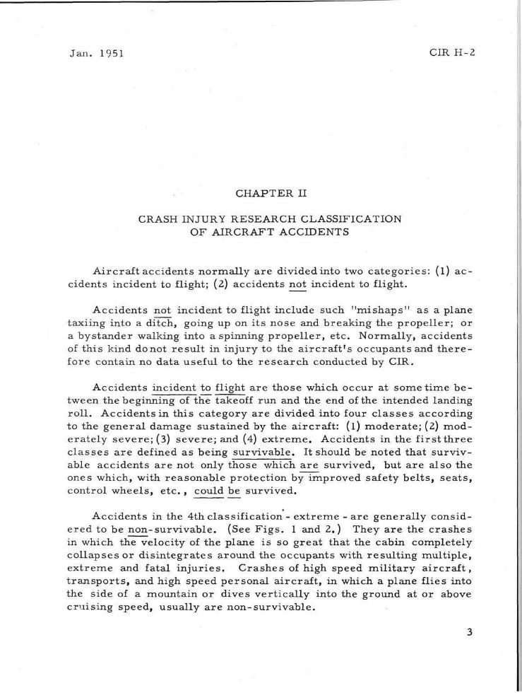
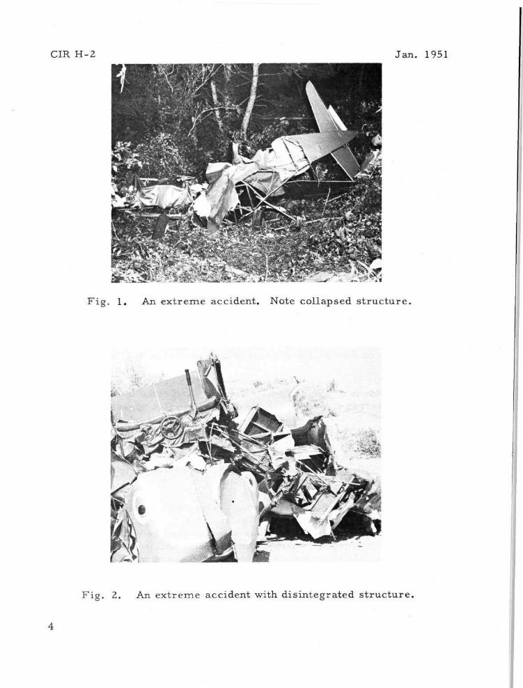
Accidents in the 4th classification - ex t reme - a re genera l ly considered to be non-surv ivable . (See F i g s . 1 and 2.) They a re the c rashes in which the velocity of the plane is so great that the cabin completely col lapses or d i s in tegra tes around the occupants with resul t ing mult iple, ex t reme and fatal in jur ies . Crashes of high speed mi l i t a ry a i r c r a f t , t r a n s p o r t s , and high speed personal a i rcraf t , in which a plane flies into the side of a mountain or dives ver t ica l ly into the ground at or above cruis ing speed, usually a re non-surv ivable .
3
CIR H-2 Jan . 1951
F ig . 1. An ext reme accident. Note collapsed s t ruc tu re .
F ig . 2. An ex t reme accident with dis integrated s t ruc ture ,

Jan . 1951 CIR H-2
The accidents which give valuable data on crash injury prob lems and provide useful information for engineers a re the survivable c rashes -the modera t e , modera te ly severe , and severe accidents . These are the accidents in which there is a definite exposure to injury, but the total energy of the c rash is not grea t enough to completely collapse the cabin s t ruc ture around the occupants . They include not only modera te acc i dents in which people a re ser iously injured or killed, but also very s e vere c r a s h e s in which no injuries occur .
An excellent example of a very severe accident in which the occupant received only b ru i s e s and sc ra tches is shown in F ig . 3. Contact with t r e e s was repor ted to have been at 90 to 100 mi les an hour; with the ground, 50 to 55 mph.
F ig . 3. A severe accident - minor in jur ies .
Two other severe but survivable accidents a re shown in F i g s . 4 and 5. In the f i rs t , the pilot - who was the only occupant of the plane - r e ceived dangerous in jur ies . The c ra sh shown in F ig . 5 resu l ted in non-dangerous injuries to the pilot; the passenger was killed.
5

CIR H-2 Jan . 1951
F ig . 4. A severe accident - dangerous injuries due to pa r t i a l collapse of cabin s t ruc tu re .
F ig . 5. Moderately severe c rash . Pi lot - non-dangerous injuries; passenger killed.
6

Jan . 1951 CIR H-2
CHAPTER III
PROCEDURE AT THE SCENE OF AN ACCIDENT
No significant improvement in the c rashwor th iness of a i rcraf t can be achieved unless engineers and manufac ture rs know what s t ruc tu res and objects within the cabin cause injur ies in survivable acc idents . The accident invest igator , in report ing the r e su l t s of a i rc raf t accidents , is providing information for the engineer, the manufacturer , and the mi l i t a ry . If he has an in te res t in accident investigation, is by na ture cu r i ous and of analytical mind, has pe r seve rance and sound judgment, his repor t ing of accident detai ls will provide re l iable and authori tat ive information.
If the accident invest igator is a State Police officer he is usually the f i rs t person with official status to reach the scene of an accident. Fo r this reason he has unusual opportunities to take photographs before the wreckage is moved, to question the pilot or other occupants , and to note crash-injury detai ls which often become unavailable at a l a te r date.
When guarding a i rc raf t wreckage, the State Pol ice officer should complete as much of the accident injury form as poss ib le , taking p a r t icular note of the condition of cockpit s t ruc tu re , safety be l t s , shoulder ha rnes s (if any) , and the s ea t s . If poss ib le , the invest igator should ask the occupants such quest ions as: "Was your safety belt (and h a r n e s s ) loose or snug? Was your shoulder h a r n e s s locked or unlocked? Do you r e m e m b e r any feeling of force during the c r a sh? Do you r e m e m b e r any detai ls of the c r a sh? What objects do you think caused your in jur ies? " These and other detai ls should be repor ted in the R e m a r k s section of F o r m AC; in the case of mi l i t a ry a i rcraf t this information will be of value to the mi l i t a ry author i t ies if the pilot is unable to r econs t ruc t detai ls of the accident at a l a te r date due to shock or death.
In the execution of his other duties - giving whatever aid poss ible , guarding the wreckage and obtaining information requ i red by his own
9

CIR H-2 Jan . 1951
organization - it i s highly des i rab le that the police officer note the pos i tions of the bodies of the occupants (if unconscious or killed), where they came to r e s t and the objects within the a i rcraf t which they may have struck. Exact knowledge of the position of each person in the wreckage is important and will furnish valuable help in determining or es tab l i shing the probable cause of injury or death.
The invest igator should t r y to recons t ruc t the basic events that led to the accident. Witnesses , occupants of the plane and others with some knowledge of the accident may be able to provide information which will help in determining how the airplane reached the position and attitude in which it came to res t ; the probable flight path, nose-down and wing-down angles and probable impact speed.
Examination of gouge m a r k s in the ground and s c a r s on t r e e s , shrubs , rocks and poles will also a s s i s t in est imating the flight path angle with the ground. Wing-t ips , p rope l l e r s and landing ge a r s leave t e l l - t a le m a r k s or bi ts of evidence indicating the points of contact with fixed objects .
The condition of the a i rc raf t , damage to cabin s t ruc ture where the occupants were sitting, the condition of sea t s , s ea t -backs , safety be l t s , shoulder h a r n e s s and other protect ive equipment should be checked off in the appropr ia te spaces on the CIR Accident Injury Report F o r m AC.
Photographs of the accident scene should be made before the plane is moved; good photographs furnish the best possible r eco rd of an acc i dent and the causes of injury. They should include the following:
(a) F o u r general views of the scene taken from four widely sepa ra t ed points showing major p a r t s of the wreckage;
(b) A genera l view back along the wreckage pa t te rn showing objec t s s t ruck by the aircraf t ;
(c) Close-up views of the cabin or cockpit a rea , showing the ins t rument panel, s ea t s , seat anchorages , safety be l t s , shoulder ha rnes s (and the i r anchorages - if damaged) , control wheels , control s t i cks , buckled tubing and other objects in the s t ruc tu re which contributed to injury;
(d) A side view showing the substantially damaged port ions of the nose and forward section of the cabin and the point of major
10

Jan. 1951 CIR H-2
impact with the ground. Information from this view, a s s i s t s CIR in est imating probable c r a s h forces to which the a i rcraf t s t ruc ture and the occupants were exposed.
Gruesome photographs showing bodies of the vict ims should be avoided unless they serve a specific, useful purpose .
Sketches that contain appropriate notations are excellent aids to a i r craft accident- injury ana lys is . Such sketches need not be works of a r t since the i r value l ies ent i re ly in the information they contain, not in their perfect ion. (See the sample sketch below, F ig . 7.)
F ig . 7. Sample sketch of an accident.
When guarding and repor t ing accident-injury detai ls of mi l i t a ry a i r craft accidents which occur outside mi l i t a ry r e se rva t ions , the police officer should make such photographs as a re permi t ted by the mi l i t a ry officer in charge of the wreckage. In some cases such pe rmi s s ion may not be granted, although it i s stated in pa ragraph f (1), section 2, chapter 8 (page 18) of the Air F o r c e Manual 62-5 that: "Outside mi l i t a ry r e s e r vations, guards will prohibit photographing of classified equipment only. P r e s e n c e of classified ma te r i a l at the scene of an accident is not a rea¬ son for prohibiting the taking of p ic tu res of the ent ire scene when the classif ied equipment can be covered or removed or otherwise kept out of any p i c t u r e s . "
11

CIR H-2 Jan . 1951
When pe rmi s s ion is not granted for photographing the accident scene, the police officer can reques t copies of photographs from appropr ia te mi l i t a ry s o u r c e s . In all c a s e s , he should obtain the name and address of the mi l i t a ry organization which took p ic tu res and note this information on the Accident-Injury Report F o r m AC.
P re se rva t ion of Evidence
When civilian a i rcraf t a r e involved in accidents in which the safety bel ts , shoulder ha rnes s or control wheels a r e broken, these objects should be obtained by the police officer before they a re picked up by souvenir hun te r s . If fai lure of such a piece of equipment is p a r t i c u l a r ly significant, the CAB, CAA, or Crash Injury Resea rch may ask - at a la te r date - to examine the object.
12

Jan . 1951 CIR H-2
CHAPTER IV
FORMS USED IN REPORTING ACCIDENT AND INJURY DETAILS
1. Notification F o r m
After the accident investigator has determined the apparent degree of injury sustained by each person involved in an accident , he should complete the Aircraf t Accident Notification F o r m (see sample on page 14) and mai l it as soon as possible to C r a s h Injury R e s e a r c h . Upon r e ceipt of this form, CIR will mail special medical forms to the attending physic ians , hospi tals and coroners request ing detailed medical data. P r o m p t n e s s in forwarding the Notification F o r m to CIR is highly desirable; detailed medical information is somet imes difficult to get if the reques t is delayed too long.
2. Aircraf t Accident-Injury Report F o r m AC
Each c rash , if considered alone, appears to be a genera l m a s s of wreckage with l i t t le apparent or sensible relat ionship between injur ies and s t ruc tu ra l causes . To the uninitiated invest igator , specific detai ls of s t ruc tu ra l failure may seem unimportant . But the invest igator should not be mis led . The specific detai ls which he obtains - when cor re la ted with data from other accidents and analyzed by CIR - show pa t te rns of s t ruc tu ra l failure which resu l t in excess ive and dangerous injur ies . These data provide the bas i s for safety design recommendat ions .
It is important , the re fore , that the invest igator complete the acc i dent- injury repor t ( F o r m AC) in i ts ent i re ty except where quest ions a re not applicable. The F o r m AC is most ly a check l i s t which r equ i r e s a min imum of t ime; mos t of the questions a re answered by m e r e l y checking the appropria te boxes . The sample accident case on pages 15-20 shows a proper ly completed repor t .
Note: The investigating officer may complete these fo rms with pen, pencil , or typewri te r . If a typewri ter is used, the original typewrit ten copy should be sent to CIR. Use of a colored typewri ter ribbon makes the forms eas ie r to read .
13

CIR H-2 Jan. 1951
SAMPLE AIRCRAFT ACCIDENT NOTIFICATION FORM
FORM C I R - N
MAIL IMMEDIATELY TO: CRASH INJURY RESEARCH, Co rne l l U n i v e r s i t y Medical C o l l e g e ,
1300 York Ave . , New York 2 1 , N.Y.
FROM: Richard F . Horton I N V E S T I G A T O R
Vermont Aeronaut ics Commission AGENCY
A SEVERE BUT SURVIVABLE ACCIDENT IN A (AIRCRAFT MAKE AND MODEL) Taylorcraft T-2
NC 58999 HAS BEEN INVESTIGATED BY PERSONNEL OF THIS OFFICE. THE ACCIDENT OCCURRED NEAR
Fort Ml! ON (DATE). 9-24-50
DETAILS OF THIS ACCIDENT HAVE BEEN OBTAINED WITH PHOTOGRAPHS SHOVING:
[X] A GENERAL VIEW OF THE DAMAGED AIRCRAFT.
[X] INTERIOR OF THE CABIN.
[X] INSTRUMENT PANEL AND CONTROL WHEELS.
[X] BROKEN SEATS OR SAFETY BELTS.
THIS MATERIAL WILL BE FORWARDED TO YOU WITH A COMPLETED ACCIDENT- INJURY REPORT FORM AT AN EARLY DATE.
THERE WERE (NUMBER) PEOPLE INVOLVED IN THIS ACCIDENT. INJURIES WERE:
• FATAL
[X] DANGEROUS
• NON-DANGEROUS
[X] TRIVIAL OR NONE
CONFIRMATION OF THE NATURE AND DEGREE OF INJURIES SHOULD BE OBTAINED FROM THE HOSPITAL. DOCTOR.
CORONER. FUNERAL HOME. OR PERSONS INVOLVED AS FOLLOWS:
PILOT: NAME:
ADDRESS:
MEDICAL INFORMATION FROM:
ADDRESS:
PASSENGER: NAME:
John J . Doe
324 E. Main S t . , Dover, Vt,.
Dr. A. Irwin Moore
82 Ardmore Dr ive , F o r t M i l l s , V t .
Arthur L,. Doe
324, E. Main St., Dover, Vt,
MEDICAL INFORMATION FROM:.
ADDRESS:
14

Jan. 1951 CIR H-2
SECTION 1 AIRCRAFT ACCIDENT AND INJURY REPORT FORM AC
Mail (with photographs of accident) to : CRASH INJURY RESEARCH, CORNELL UNIVERSITY MEDICAL COLLEGE, 1300 YORK AVE., NEW YORK 2 1 , N.
ACCIDENT LOCATION: Fort Mills, Webster
(CITY. TOWN, OR TOWNSHIP)
AIRCRAFT: MAKE: T - c r a f t MODEL: L-2 OF MFG.:
(COUNTY)
1942
Vt. ( S T A T E )
REG. No.N- 58999
DATE: 9-24-50 T I M e : 10:15
SERIAL NO.: 23971
TOTAL HOURS: 870
OWNER'S NAME: Skyways Flying Service
OWNER S Address: Municipal Airport. Dover, Vt.
FILL IN PILOT'S TOTAL FLYING HOURS. NAMES. ADDRESSES
AND WEIGHTS OF PILOT AND PASSENGERS. CHECK SEATED POS
ITIONS AND APPARENT DEGREE OF INJURY OF EACH OCCUPANT.
PILOT
PASS.
PASS.
PASS.
PASS.
NAME: J o h n R . D o e HOURS: 1 9 0
ADDRESS: 324. E. Main S t . , Dover, V t . Ar thur L. Doe, age 12
(same address )
165
100
SEATED POSITIONS
FRONT
REAR
LEFT
CENTER
RIGHT
MINOR-
NONE
INJURIES
NON-
DANGEROUS
DANGEROUS
FATAL
GIVE BRIEF DESCRIPTION OF NATURE AND CAUSE OF ACCIDENT: INCLUDE WEATHER (WIND DIRECTION AND VELOCITY, CEILING
AND VISIBILITY); TERRAIN (HILLY. FLAT. WOODED. SUBURBAN. OPEN. ETC.); MANEUVERS PRIOR TO ACCIDENT AND OTHER
CONTRIBUTING FACTORS INCLUDING ESTIMATED ALTITUDE OF AIRCRAFT IN MANEUVER WHICH RESULTED IN ACCIDENT.
Weather clear, unlimited ceiling and visibility, wind northwest, 10 mph. Terrain - flat open fields near Fort Mills Airport. The plane took off toward the north into a quartering headwind. As the plane climbed to 150 feet, the engine quit and the pilot allowed the plane to stall. It. fell off to the left in a nose-down attitude and struck the ground in an open field, headed south. The plane was not spinning at the moment of impact; it struck almost simultaneously on the left gear and nose.
OBSTACLES AIRCRAFT HIT BEFORE FINAL IMPACT:
WIRES • TREES • BRUSH •
IF OTHER DESCRIBE:
PARTS OF AIRCRAFT INVOLVED IN COLLISION WITH OBSTACLES:
NOSE • WING(S) • LANDING GEAR • TAIL •
IF OTHER DESCRIBE:
INDICATE ESTIMATED FLIGHT PATH ANGLE OF AIRCRAFT
WITH GROUND BEFORE HITTING OBSTACLES: DEGREES
INDICATE ESTIMATED FLIGHT PATH ANGLE OF AIRCRAFT
WITH GROUND AT PRINCIPAL IMPACT: DEGREES 40
INDICATE ESTIMATED SPEED OF AIRCRAFT
BEFORE HITTING OBSTACLES: MPH.
INDICATE ESTIMATED SPEED OF AIRCRAFT
AT PRINCIPAL IMPACT: 50 MPH.
WING DOWN ANGLE (WITH GROUND) AT PRINCIPAL IMPACT:
INDICATE DIRECTION OF WIND IN RELATION TO DIRECTION OF
AIRCRAFT AT PRINCIPAL IMPACT: HEADWIND • 45° HEADWIND D TAILWIND • 45° TAILWIND [X] CROSSWIND •
PRINCIPAL IMPACT WAS AGAINST: IF OTHER. DESCRIBE:
TREES • WATER • BUILDING D SOFT GROUND [X] HARD GROUND [X] ROCKY GROUND • PAVEMENT []
INDICATE STOPPING DISTANCE OF PLANE; IN FEET. AFTER PRINCIPAL IMPACT:
SLID: FEET CARTWHEELED: FEET BOUNCED: 20 FEET ROLLED: FEET
INDICATE LENGTH AND DEPTH OF GOUGE MARKS:
LENGTH (IN FEET) 6. . DEPTH (IN INCHES) 4
INDICATE DISTANCE NOSE TELESCOPED TOWARD PILOT'S SEAT:
TELESCOPED: FEET: 1 INCHES: 3
WAS LANDING GEAR: UP D DOWN [J WERE FLAPS: UP [] DOWN • DEGREES?.
15
NOSE DOWN ANGLE (WITH GROUND) AT PRINCIPAL IMPACT:
IF INVERTED OR NOSE UP. DESCRIBE. GIVING ANGLE:_
CAA
APPROX.
WEIGHT

CIR H-2 Jan. 1951
S E C T I O N 2
INDICATE DISTANCE ENGINE DISPLACED:
ENGINE DISPLACED (DIRECTION)
INDICATE CONDITION OF:
DETAILS OF DAMAGE TO AIRCRAFT*
FEET:
LEFT [X] RIGHT •
TORN FREE []
FORWARD []
INTACT
UP [X]: DOWN
ENGINE MOUNT
ENGINE COWLING
FIREWALL
FIREWALL DISPLACED: FEET
CABIN (OR COCKPIT) AREA*
FUSELAGE (AFT OF CABIN AREA)
TAIL SURFACES
INSTRUMENT PANEL*
WINDSHIELD (PLEXIGLAS. ETC.)
FRONT DIAGONAL BRACES
RUDDER PEDALS
FLOORING (MATERIAL? Metal )
OVERHEAD CABIN STRUCTURE*
LEFT WING(S)*
RIGHT WING(S)*
LEFT CONTROL WHEEL
RIGHT CONTROL WHEEL
LEFT CONTROL COLUMN (SHAFT)*
RIGHT CONTROL COLUMN (SHAFT)*
LEFT (OR FRONT) CONTROL STICK
RIGHT (OR REAR) CONTROL STICK
NOSE LANDING GEAR
LEFT MAIN LANDING GEAR
RIGHT MAIN LANDING GEAR
NOSE GEAR WAS DISPLACED
LEFT GEAR WAS DISPLACED
RIGHT GEAR WAS DISPLACED
WAS BATTERY INSTALLED IN PLANE?
WHERE WAS BATTERY FOUND AFTER ACCIDENT
DID FIRE OCCUR FOLLOWING ACCIDENT?
STALL WARNING INDICATOR INSTALLED?
INTACT D
INTACT D
INTACT •
INCHES
INTACT •
INTACT •
INTACT [X]
INTACT D
INTACT []
INTACT D
INTACT []
INTACT []
INTACT []
INTACT •
INTACT •
INTACT D
INTACT D
INTACT •
INTACT •
BENT D
BENT [X]
BUCKLED 12
BUCKLED [X]
COLLAPSED •
DISINTEGRATED 0
BENT D BUCKLED [X] DISINTEGRATED •
3" to 9" DIRECTION? top part into cabin DISTORTED [X] PARTLY COLL. [X] COLLAPSED D
DISTORTED D
DISTORTED []
DISTORTED []
KNOCKED OUT
BENT [X] *2
BENT [X]
BENT [X]
BENT [X]
DISTORTED []
DISTORTED [X]
INTACT DC (loose) INTACT []
INTACT D
INTACT []
INTACT D
UP •
UP [X]
UP [X]
YES •
YES D
YES •
* ADDITIONAL INFORMATION AND/OR REMARKS:
BENT D
BENT •
BENT D
BENT •
BENT D
BENT []
BENT D
BENT D
BENT •
BACK •
BACK [X]
BACK (2
NO •
NO [X]
NO [X]
PARTLY COLL. [X]
PARTLY COLL. D
COLLAPSED •
COLLAPSED D
DENTED [X] * 1 TORN FREE •
IN ONE PIECE []
BUCKLED [X]
BROKEN []
BROKEN •
PARTLY COLL. D
(outer 6' CRUMPLED [X]/
CRUMPLED •
BROKEN D
BROKEN •
BROKEN •
BROKEN D
BUCKLED []
BUCKLED •
BUCKLED D
BUCKLED [X]
BUCKLED [X]
FORWARD •
FORWARD D
FORWARD D
WIRES BROKEN AT
IMMEDIATELY []
OPERATING D
BROKEN [X]
COLLAPSED D
TORN FREE D
COLLAPSED •
COLLAPSED D
of wing) TORN FREE D
TORN FREE D
JAGGED
JAGGED
TORN FREE []
TORN FREE •
TORN FREE 0
and upward DISINTEGRATED •
DISINTEGRATED D
DISINTEGRATED D
DISINTEGRATED •
DISINTEGRATED []
DISINTEGRATED •
DISINTEGRATED •
DISINTEGRATED •
DISINTEGRATED D
DISINTEGRATED []
DISINTEGRATED •
SPOKES EXPOSED D
SPOKES EXPOSED D
COLUMN END EXPOSED []
COLUMN END EXPOSED D
BROKEN D
BROKEN D
COLLAPSED D
COLLAPSED D
COLLAPSED D
LEFT D
LEFT [X]. LEFT D
BATTERY? YES []
TORN FREE D
TORN FREE D
TORN FREE D
TORN FREE 0
TORN FREE []
RIGHT []
RIGHT []
RIGHT •
NO []
HOW MANY SECONDS LATER?
INOPERATIVE [] UNKNOWN D
16
IF
ACC
IDEN
T W
AS
SURV
IVED
O
R
REG
ARD
ED
AS
SU
RV
IVA
BLE
, F
ILL
OU
T SE
CTI
ON
S 1
, 2
A
ND
3.
*l. Broken on r ight s ide . Cross tube at bottom bent. Damage probably due to p i l o t ' s body.
*2. Right diagonal tube bent forward, possibly by p i l o t ' s head.
WERE PHOTOGRAPHS TAKEN OF ACCIDENT?_Yes BY WHOM? NAME Richard F . Horton ADDRESS Vermont Aeronaut ics Commission
INVESTIGATOR'S SIGNATURE TITLE I n s p e c t o r
Montpe l i e r , Vt . Vermont Aeronau t ics Commission 1 0 - 1 - 5 0 INVESTIGATORS ADDRESS AGENCY DATE OF REPORT

J a n . 1951 CIR H-2
SECTION 3 INJURY DETAIL: THIS SECTION TO BE FILLED OUT FOR ONE PERSON WHETHER INJURED OR NOT,
(USE ADDITIONAL SECTION 3 'S FOR ADDITIONAL PERSONS)
NAME: John R. Doe ADDRESS: 324 E. Main S t . , Dover, V t . SAMPLE
PLACE OF ACCIDENT: Fort Mills , Vt. DATE: 9-24.-50
TREATMENT GIVEN:
DOCTOR'S NAME: A. Irwin Moore NAME OF HOSPITAL:_
UNDERTAKER'S NAME:
Memorial Hospital
FIRST AID [X] HOSPITALIZED [X] TAKEN TO UNDERTAKER []
ADDRESS: 82 Ardmore Dr ive , For t M i l l s , Vt . ADDRESS:
ADDRESS:
For t M i l l s , Vt.
BRIEFLY DESCRIBE APPARENT INJURIES SUSTAINED BY THIS PERSON: YOUR OBSERVATION DOCTOR'S D
Concussion. Unconscious for about 30 minutes. Deep cuts of the left forehead and right jaw. Chest bruises. Fractures of the left wrist, left and right ankles. Cuts of the right knee.
SEAT OCCUPIED BY THIS PERSON: FRONT
TYPE OF SEAT FIXED
CONDITION OF SEAT* INTACT
CONDITION OF SEAT-BACK* INTACT
CONDITION OF SEAT ANCHORAGES INTACT
CABIN CONDITION NEAR THIS SEAT* INTACT
DURING CRASH THIS PERSON WAS THROWN UP
REAR D LEFT
ADJUSTABLE FORE AND AFT
DISTORTED • PARTLY COLL.
DISTORTED [X]*lPARTLY COLL.
DISTORTED D FRONT BROKEN
DISTORTED • PARTLY COLL.
DOWN D FORWARD
CENTER D RIGHT
ADJUSTABLE UP AND DOWN
COLLAPSED
COLLAPSED
REAR BROKEN
COLLAPSED
LEFT
TORN FREE
TORN FREE
TORN FREE
DISINTEGRATED
RIGHT
INSIDE CABIN [X] OUTSIDE CABIN [] DESCRIBE WHERE PERSON CAME TO REST: On forward
edge of seat, chest against instrument panel, head against right doorpost.
WAS THERE ANY INDICATION THAT THIS PERSON HIT:
DIAGONAL BRACES [X]
OVERHEAD BRACES []
CONTROL WHEEL SPOKES D
RUDDER PEDALS £2
IF OTHER. EXPLAIN:
WAS THIS PERSON
WEARING SAFETY BELT? YES [X]
WIDTH OF SAFETY BELT 2" [X]
WAS SAFETY BELT INTACT •
WAS SAFETY BELT CUT BY:
BELT ANCHORAGES: INTACT
WINDSHIELD •
DOORPOSTS D
HUB •
BRAKE PEDALS [X]
INSTRUMENT PANEL [X]
WINDSHIELD FRAME •
INSTRUMENTS
CANOPY
SIDE BRACES [] COWLING [] ENGINE
CONTROL COLUMN (SHAFT) [] END OF SHAFT
BACKREST OF FRONT SEAT [] FLOORING
NO •
3" •
STRAINED •
PARTLY TORN [X]
TORN THROUGH [X]
BUCKLE •
BENT D
SHOULDER (OR CHEST) HARNESS INSTALLED? YES []
HARNESS: INTACT • DAMAGED •
HARNESS ANCHORAGE:INTACT • BROKEN •
MAKE: Flyco MODEL NC. A-12
LICENSED FOR 1 PERSON []
DID WEBBING SHOW DETERIORATION? YES [X]
IF SO. WHERE?
IF SO. WHERE?
MFG. DATE:.
FOR 2 PERSONS
1946
About 2" from right attachment. ADJUSTING ADAPTER (L) []:(R) []
BROKEN (L) []: (R) •
END ATTACHMENT (L) D:
TORN OUT (L) •:
NO [X] DID PERSON WEAR HARNESS? YES []
DESCRIBE:
DESCRIBE:
NO []
(R) []
(R) []
NO []
WAS THIS PERSON INJURED BY OBJECTS OR OTHER OCCUPANTS BEING THROWN ON HIM?
IF YES. DESCRIBE:
YES D NO [X]
*ADDITIONAL INFORMATION AND/OR REMARKS: (IN THE LAST ANALYSIS. THE INVESTIGATOR'S EVALUATION OF A CRASH GIVES MANUFACTURERS AND OTHER GROUPS CONCERNED WITH SAFETY A DEPENDABLE BASIS FOR JUDGING SAFETY NEEDS. WERE INJURIES CAUSED PRIMARILY BY THE TELESCOPING OF STRUCTURE OR BY BEING THROWN AGAINST OBJECTS INSIDE THE CABIN? IF YOU HAD BEEN IN THIS ACCIDENT. WHAT IMPROVEMENTS DO YOU FEEL MIGHT HAVE DECREASED DANGER OF INJURY?)
*1. Top bent forward about 1" to 2", probably from rear seat occupant bracing himself on forward seat-back. (Canvas over backrest was ripped off when removing front seat occupant.)
*2. A piece of tubing (near left front window post) broke and projected into the cabin; fortunately it caused no serious injury. The cabin was in bad shape but remained sufficiently intact to afford some protection.
Failure of safety belt probably contributed to overall injuries, particularly of the legs. A stronger safety belt and use of shoulder harness would probably have prevented the dangerous head injuries.
17
HANDLES
KNOBS
CONTROL WHEEL
CONTROL STICK
CABIN ROOF
IF
AC
CID
EN
T W
AS
SUR
VIV
ED
O
R
RE
GA
RD
ED A
S
SUR
VIV
AB
LE
, F
ILL
O
UT
SE
CT
ION
S 1,
2
AN
D 3
.

CIR H-2 Jan. 1951
SECTION 3 INJURY DETAIL: THIS SECTION TO BE FILLED OUT FOR ONE PERSON WHETHER INJURED OR NOT,
(USE ADDITIONAL SECTION 3'S FOR ADDITIONAL PERSONS)
NAME: Ar thur L. Doe ADDRESS; 324 E. Main S t . . Dover, Vt . PLACE OF ACCIDENT: F o r t M i l l s , V t . DATE: 9-24-50
TREATMENT GIVEN:
DOCTOR'S NAME:
NAME OF HOSPITAL:_
UNDERTAKER'S NAME:.
A. Irwin Moore FIRST AID [X] HOSPITALIZED [] TAKEN TO UNDERTAKER D
ADDRESS: 82 Ardmore D r i v e , F o r t M i l l s , Vt.
ADDRESS:
ADDRESS:
BRIEFLY DESCRIBE APPARENT INJURIES SUSTAINED BY THIS PERSON: YOUR OBSERVATION DOCTOR'S •
Cuts of left ankle. Bruise on back of right hand. Sprained right wrist.
SEAT OCCUPIED BY THIS PERSON: FRONT
TYPE OF SEAT FIXED
CONDITION OF SEAT* INTACT
CONDITION OF SEAT-BACK* INTACT
CONDITION OF SEAT ANCHORAGES INTACT
CABIN CONDITION NEAR THIS SEAT* INTACT
DURING CRASH THIS PERSON WAS THROWN UP
INSIDE CABIN
REAR [X] LEFT
ADJUSTABLE FORE AND AFT
DISTORTED [] PARTLY COLL.
PARTLY COLL.
FRONT BROKEN
PARTLY COLL.
FORWARD
DISTORTED •
DISTORTED •
DISTORTED [X]
DOWN •
OUTSIDE CABIN []
CENTER • RIGHT •
ADJUSTABLE UP AND DOWN []
COLLAPSED D
COLLAPSED •
REAR BROKEN D
COLLAPSED •
LEFT D
TORN FREE []
TORN FREE •
TORN FREE •
DISINTEGRATED []
RIGHT [X]
DESCRIBE WHERE PERSON CAME TO REST: In Seat.
WAS THERE ANY INDICATION THAT THIS PERSON HIT:
DIAGONAL BRACES • WINDSHIELD []
OVERHEAD BRACES [] DOORPOSTS []
CONTROL WHEEL SPOKES [] HUB []
RUDDER PEDALS [] BRAKE PEDALS [X]
IF OTHER. EXPLAIN:
INSTRUMENT PANEL •
WINDSHIELD FRAME []
INSTRUMENTS • HANDLES
CANOPY • KNOBS
SIDE BRACES [] COWLING [] ENGINE • CONTROL WHEEL
CONTROL COLUMN (SHAFT) • END OF SHAFT • CONTROL STICK
BACKREST OF FRONT SEAT [X] FLOORING • CABIN ROOF
WAS THIS PERSON
WEARING SAFETY BELT? YES
WIDTH OF SAFETY BELT 2"
WAS SAFETY BELT INTACT
WAS SAFETY BELT CUT BY:
BELT ANCHORAGES: INTACT []
NO
3" STRAINED
PARTLY TORN
TORN THROUGH
BUCKLE
BENT
SHOULDER (OR CHEST) HARNESS INSTALLED? YES
HARNESS: INTACT [] DAMAGED
HARNESS ANCHORAGE:INTACT [] BROKEN
MAKE: FlyCO MODEL NO. :_A-12 MFG. DATE: 1946
LICENSED FOR 1 PERSON • FOR 2 PERSONS [X]
DID WEBBING SHOW DETERIORATION? YES [X] NO []
IF SO. WHERE?
IF SO. WHERE?
ADJUSTING ADAPTER (L) []:(R) []
BROKEN (L) []: (R) •
END ATTACHMENT (L) D:
TORN OUT (L) D:
NO [X] DID PERSON WEAR HARNESS? YES D
DESCRIBE:
DESCRIBE:
(R) [] (R) []
NO []
WAS THIS PERSON INJURED BY OBJECTS OR OTHER OCCUPANTS BEING THROWN ON HIM?
IF YES. DESCRIBE:
YES D NO [X]
*ADDITIONAL INFORMATION AND/OR REMARKS: (IN THE LAST ANALYSIS. THE INVESTIGATOR'S EVALUATION OF A CRASH GIVES MANUFACTURERS AND OTHER GROUPS CONCERNED WITH SAFETY A DEPENDABLE BASIS FOR JUDGING SAFETY NEEDS. WERE INJURIES CAUSED PRIMARILY BY THE TELESCOPING OF STRUCTURE OR BY BEING THROWN AGAINST OBJECTS INSIDE THE CABIN? IF YOU HAD BEEN IN THIS ACCIDENT. WHAT IMPROVEMENTS DO YOU FEEL MIGHT HAVE DECREASED DANGER OF INJURY?)
Boy stated that he braced himself by holding onto backrest of front seat when he "saw ground coming up at him".
18
IF ACCIDENT WAS SURVIVED OR REGARDED AS SURVIVABLE, FILL OUT SECTIONS 1, 2 AND 3.

Jan. 1951 CIR H-2
19

Jan. 1951 CIR H-2
CHAPTER V
GENERAL ACCIDENT DATA (Section 1)
Some c rash- in ju ry detai ls of an accident a re not always readi ly apparent and may be overlooked. To forestal l this possibi l i ty , the F o r m AC has been ar ranged so that the investigation can be conducted in logical o rde r . All the i t ems l i s ted are important . Since the reasons for request ing cer ta in information may not be apparent , descr ip t ions and explanations of i tems on the check l is t a re outlined in the following pages . D i a g r a m s , i l lus t ra t ions and explanatory ma te r i a l a re given in the order in which the i tems appear on the Aircraf t Accident-Injury Report F o r m AC. (See sample F o r m AC, pages 15-18.)
DATE and TIME of accident: - These a re important fac tors in CIR's determinat ion of degree of injury, for if a pe rson dies m o r e than 24 hours after an accident the injury is c lassed as cr i t ica l ; if death occurs within 24 hours the degree of injury is given a higher value. "Date and T i m e " also a r e frequently re la ted to cause of accident and make it possible to check back la te r on such factors as wind direct ion, visibil i ty, darkness and other weather conditions.
F ig . 8. Sample Regis t ra t ion Certificate ca r r i ed in a i rc raf t .
21

CIR H-2 Jan . 1951
AIRCRAFT: - The Make (manufacturer - i . e . , "P iper , Temco, Stinson", e tc . ) ; Model ("170", "35-A", e t c . ) ; CAA Regis t ra t ion Number , and Se r i al Number a r e ex t remely important - pa r t i cu la r ly the Serial Number . This data may be found on the Regis t ra t ion Certif icate which is usually displayed prominent ly in the cabin or cockpit. (See F ig . 8.) If the C e r tificate is lost or destroyed the information may be obtained from a meta l identification plate attached to cabin s t ruc tu re . The CAA Regis t ra t ion Number is also painted on the wings and tai l of the a i rcraf t .
A manufacturer may make changes in design or m a t e r i a l s of seat fastenings, control wheels, safety belts and the i r anchorages , and other equipment during the production of one model . Often these changes cannot be detected by the accident invest igator , but the se r ia l number will indicate to CIR whether the airplane does or does not have cer ta in i m proved s t ruc tu r e s or ins ta l la t ions .
PILOT'S TOTAL FLYING HOURS: - This information is not always avai l able, but if obtainable is often helpful in evaluating the accident .
APPROXIMATE WEIGHT OF PILOT AND PASSENGERS: - This information is ex t remely important as it enables CIR to judge the forces exer ted on safety be l t s , sea t s , seat anchorages and shoulder h a r n e s s .
SEATED POSITIONS AND APPARENT DEGREE OF INJURY: - Cha rac t e r i s t i c "pat terns of injury" a re often caused by specific s t ruc tu re s in cer ta in types of p lanes . In o rde r that these pa t te rns may be identified and evaluated, it is very important to know where each person was s i t ting at the t ime of impact and the apparent extent of injury (or lack of injury) of each occupant. (See F ig . 9.)
22

J a n . 1951 CIR H - 2
In a p l ane c r a s h s o m e of the p a s s e n g e r s m a y be e x p o s e d to g r e a t e r i n j u r y than o t h e r s . G e n e r a l l y the o c c u p a n t s of the f ron t s e a t s of t a n d e m and f o u r - p l a c e a i r c r a f t a r e m o r e l i k e l y to be i n j u r e d t h a n the p e o p le in the r e a r s e a t s .
Al though the a c c i d e n t i n v e s t i g a t o r n e e d not get d e t a i l e d , spec i f i c m e d i c a l d a t a on each p e r s o n , it i s e s s e n t i a l tha t he r e p o r t the full n a m e and a d d r e s s of the p h y s i c i a n s , h o s p i t a l s , o r u n d e r t a k e r s who took c h a r g e of the a c c i d e n t v i c t i m s . Upon r e c e i p t of the Not i f ica t ion F o r m o r F o r m A C , C r a s h In ju ry R e s e a r c h wil l m a i l s p e c i a l m e d i c a l f o r m s to the a t t end ing p h y s i c i a n s or c o r o n e r with a r e q u e s t for d e t a i l e d i n j u r y d a t a .
T h e i n v e s t i g a t o r should c l a s s i f y the i n j u r i e s b r o a d l y a s M i n o r -None , N o n - D a n g e r o u s , D a n g e r o u s , or F a t a l . A g e n e r a l c l a s s i f i c a t i o n of a p p a r e n t i n j u r i e s i s g iven below:
M i n o r i n j u r i e s - M i n o r c o n t u s i o n s , l a c e r a t i o n s , a b r a s i o n s and s p r a i n s ; f r a c t u r e s of the f i n g e r s , t o e s , o r n o s e .
N o n - D a n g e r o u s i n j u r i e s - M o d e r a t e o r s e v e r e c o n t u s i o n s ( b r u i s e s ) , l a c e r a t i o n s ( cu t s ) , a b r a s i o n s , s e v e r e s p r a i n s ; f r a c t u r e s of the fee t , l e g s , h a n d s , a r m s , j aw , f ac i a l b o n e s ; l o s s of c o n s c i o u s n e s s up to 30 minutes; s p r a i n s of t he b a c k and n e c k .
D a n g e r o u s i n j u r i e s - F r a c t u r e s of t he back , n e c k , o r skul l wi th o r wi thout p a r a l y s i s ; c r u s h i n g i n j u r i e s of a r m s o r l e g s , m u l t i p l e f r a c t u r e s , m u l t i p l e l a c e r a t i o n s with h e m o r r h a g e , l o s s of c o n s c i o u s n e s s of m o r e t h a n 30 m i n u t e s .
F a t a l i n j u r i e s - I n j u r i e s which c a u s e dea th wi th in 24 h o u r s . C o m m o n c a u s e s of f a t a l i ty in s u r v i v a b l e a c c i d e n t s a r e h e a d i n j u r i e s , c r u s h ing i n j u r i e s of the c h e s t , f r a c t u r e of t he n e c k or b a c k , s e v e r e h e m o r r h a g e s and p u n c t u r e i n j u r i e s of t he h e a d or body.
B R I E F D E S C R I P T I O N O F NATURE AND CAUSE O F A C C I D E N T : - F a c t o r s s u c h a s w e a t h e r and t e r r a i n often c a u s e a c c i d e n t s o r c o n t r i b u t e to a c c i d e n t r e s u l t s . Wind f r equen t l y i n f l uences a c c i d e n t r e s u l t s and it i s t h e r e f o r e i m p o r t a n t to g ive wind d i r e c t i o n and v e l o c i t y and the c o m p a s s d i r e c t i o n in which the p l a n e w a s h e a d e d at the t i m e of p r i n c i p a l i m p a c t . If the a c c i d e n t o c c u r r e d on s loping t e r r a i n , m e n t i o n w h e t h e r the p l ane h i t going uphi l l o r downhi l l o r p a r a l l e l to the s ide of the h i l l .
23

CIR H-2 Jan . 1951
Information on maneuvers p r io r to the accident is valuable in e s timating the impact angle and speed of the plane at impact.
Whenever a plane hi ts an obstruction, t r y to get the approximate height of the point where the plane s truck. In cases where a plane goes out of control nea r the ground and spins or sp i ra l s into the ground, t ry to get an es t imate of the altitude at which it went out of control . This is somet imes r a the r difficult since wi tnesses who a re not pilots often give very e r roneous and conflicting altitude e s t ima tes . Fo r purposes of compar ison , 100 feet is the height of an average 8 to 10-s tory building, or the 45° sightline on the back cover of this Handbook can be used to find the height of objects. See Appendix A and explanation.
Obstacles Aircraf t Hit before Final Impact: - Striking wi re s , t r e e s , and other obstacles at flying speed usually will absorb a good deal of energy and slow down a plane p r io r to the principal impact . Information as to what par t of the plane hit the obstruction will give indication of the forces imposed upon var ious pa r t s of the plane and somet imes will indicate the direction in which the occupants were "thrown".
Indicate Es t ima ted Flight Pa th Angle of Aircraf t with Ground before Hitting Obstac les : - The flight path angle of an airplane as it descends to ward the ground may be quite different from the angle of the fuselage to the ground. Jus t before hitting an obstacle, a plane may be "pulled up" into a nose-high attitude (see F ig . 10) in an at tempt to avoid a collision, but may continue to "mush" downward toward the ground.
F ig . 10. Fl ight path angle is angle of descent, often differing from nose-down or nose-up angle.
24
Jan. 1951 CIR H-2
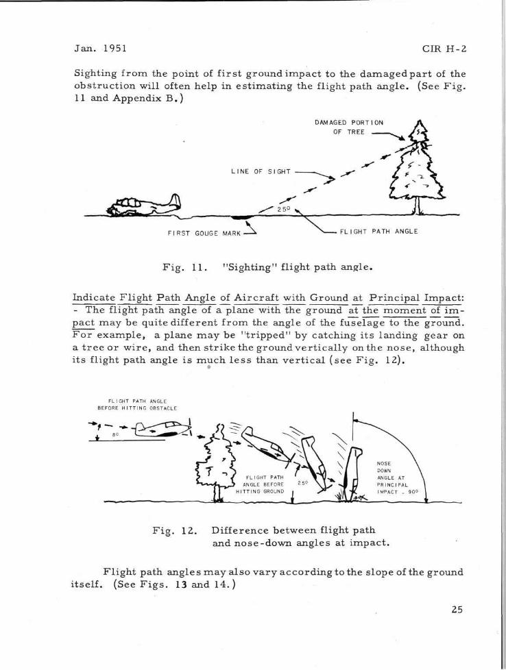
Sighting from the point of f i rs t ground impact to the damaged par t of the obstruction will often help in est imating the flight path angle. (See F ig . 11 and Appendix B.)
DAMAGED PORTION OF TREE
FIRST GOUGE MARK FLIGHT PATH ANGLE
Fig . 11. "Sighting" flight path angle.
Indicate Flight Path Angle of Aircraf t with Ground at Pr inc ipa l Impact: - The flight path angle of a plane with the ground at the moment of i m pact may be quite different from the angle of the fuselage to the ground. Fo r example, a plane may be "tr ipped" by catching i ts landing gear on a t r ee or wire , and then s t r ike the ground ver t ical ly on the nose, although its flight path angle is much l e s s than ver t ica l (see F ig . 12).
FLIGHT PATH ANGLE BEFORE HITTING OBSTACLE
Fig . 12. Difference between flight path and nose-down angles at impact .
Fl ight path angles may also vary according to the slope of the ground itself. (See F ig s . 13 and 14.)
25

CIR H-2 Jan. 1951
F ig . 13. F ig . 14.
F ig . 15. F ig . 16.
Differences in flight path angles due to different ground angles.
An airplane descending and hitting on a downhill slope would have a very different flight path angle with the ground from that of a plane hitting on an uphill slope (see F ig . 15). An airplane flying along a h o r i zontal flight path into a ver t ica l cliff would have a flight path angle of 90° to the cliff (see F ig . 16).
Speed of Ai rcraf t before Hitting Obstacles : Speed of Ai rcraf t at Pr inc ipa l Impact: - It i s general ly possible to e s t i mate the speed of the airplane before hitting obstacles and at impact by questioning qualified wi tnesses and by considering the cruis ing, approach, and stalling speeds of the plane, i ts maneuver s , and the wind.
If the plane s t r ikes w i r e s , t r e e s , or other obstacles at flying speed, a great deal of energy may be absorbed, slowing down the plane before impact with the ground. In such cases it i s difficult to make m o r e than
26

Jan. 1951 CIR H-2
an "educated guess" as to the final ( impact) speed. Make the best pos sible es t imate of the probable c ra sh speed. CIR will then check the deta i ls of the accident, the s t ruc tura l col lapse, and other factors against s imi la r cases to "average out" any d iscrepancy which may occur in e s t imating probable impact speed.
The effect of wind on impact speed can be es t imated by use of the d iagram below.
SUBTRACT
Fig . 17. Diagram for es t imat ing wind effect on impact speed.
F o r example, if a plane with a stalling speed of 50 mph were headed into a wind of 20 mph pr io r to, and at, impact , the impact speed would be approximately 30 mph. If, however, the plane were headed downwind (with the wind), the velocity of the wind would be added to that of the plane and would resu l t in an impact speed of 70 mph. If the wind were from the side, a l e s s e r amount would be added or subtracted depending on the direct ion of the wind in relat ion to that of the a i rc ra f t .
Nose-Down Angle (With Ground) at Pr inc ipa l Impact: - The nose-down
F ig . 18.
27

CIR H-2 Jan . 1951
angle is the attitude of the plane at the moment it hits the ground or other object of pr incipal impact. This angle is often different from the flight path angle (see F i g s . 19 and 20).
Nose-down angle (with ground) at pr incipal impact . (Note difference between nose-down and flight path angles.)
F ig . 21. Damage to engine, cowling and landing gear indicates probable nose-down angle at pr incipal impact .
Occasionally a plane will hit at a steep angle and "stick like an a r row" , but more often it will bounce, car twheel , or slide after initial impact , coming to r e s t in some other att i tude. If this occurs , check such i t ems as the deflection angle of the landing gear , damage to the wings (especially the wing- t ips ) , buckling of the cowling, displacement of the engine, and damage to the bottom of the f irewall . (See F ig . 21.) If witne s se s a re available, they may be of ass i s tance in est imating the n o s e -
28

Jan . 1951 CIR H-2
down angle if they a re shown the i l lus t ra t ions in the F o r m AC (Fig. 18).
If the plane was pas t ver t ica l ( inver ted) at the pr incipal impact , indicate this fact in the proper space with an es t imate of the nose-down angle.
Wing-Down Angle (With Ground) at P r inc ipa l Impact: - Damage to the wings, landing gear , distort ion of the fuselage and other p a r t s of the plane, plus wi tnesses ' s ta tements , will a s s i s t in es t imat ing whether the plane s t ruck heavily on one wing and if so, the angle of the wings to the ground. Note that the planes in the d iagram a re shown as "left wing
AIRCRAFT LEVEL LEFT WING STRIKES SLOPING GROUND
Fig . 23. Effect of sloping ground on "wing-down" angle.
Indicate Direct ion of Wind in Relation to Direct ion of Ai rcraf t at P r i n c i pal Impact: - It is important , in calculating impact speeds , to know whether the airplane was going with, a c r o s s , or against the prevai l ing surface wind at the t ime of impact. (See F ig . 24.) If the wind direct ion
29
down" or "right wing down" as seen from behind the a i rp lane . If the wing-down angle is other than those indicated above the boxes , as for example 50°, ei ther place "X"s in both the 40° and 60° boxes or wri te in the numera l "50" between the appropria te boxes.
A plane descending in a wing-level attitude and str iking one wing tip against sloping t e r r a i n , as in F ig . 23, would be r epor ted as having a "wing-down" angle of, in this case , 30° due to the fact that the slope of the ground is 30° to the wing.

CIR H-2 Jan . 1951
was between those indicated by the boxes, put "X"s in the two most appropr ia te boxes . Fo r example, if the wind was between a d i r ec t headwind and a 45 headwind, put "X"s in those two boxes.
HEADWIND
4 5 ° HEADWIND 4 5 ° HEADWIND
CROSSWIND CROSSWIND
45° TAILWIND 45° TAILWIND
Fig . 24. Wind direct ion in relat ion to direct ion of a i rc raf t at pr incipal impact .
Pr incipal Impact Was Against: - There is a t remendous variat ion in the energy absorbing cha rac t e r i s t i c s of various objects s t ruck by a i rp lanes in accidents . F o r instance, soft ground will absorb a great deal more energy than pavement . It is therefore important that you indicate what the principal impact was against , so that the probable c rash forces exe r t ed on the plane and occupants can be more closely es t imated by CIR.
Stopping Distance of Plane: - Everyone knows that i t ' s not how fast you a re going that counts, - i t ' s how fast you stop. The distance through which a p lane 's speed is stopped is mos t important . A c ra sh is an absorption of kinetic energy. Crash energy is dissipated by (1) sliding, roll ing, bouncing, or cartwheeling along the ground; (2) by gouging into the ground; (3) by deformation, buckling, or crushing of a i rc raf t s t ruc tu res ; and (4) by crumpling or breaking of objects the airplane s t r i k e s .
In low-angle accidents , planes frequently sl ide, bounce or c a r t wheel for 100 feet or m o r e . On the other hand, in a very high-angle ac cident (steep nose-down angle) a plane may not move from the point of pr incipal impact , the nose of the ship burying itself in the ground. In such accidents , the speed is stopped and the energy is absorbed in the
30

Jan. 1951 CIR H-2
collapse of s t ruc ture and in gouging into the ground. This distance can usually be quite accura te ly measured .
Length and Depth of Gouge Marks : - The length and depth of gouge m a r k s are i tems of ext reme impor tance , especial ly in high - angle accidents , for they provide valuable information which is used, along with other data, to es t imate the c r a sh forces t r ansmi t t ed to cabin s t ruc tu re , sea t s , safety be l t s , shoulder h a r n e s s and to the occupants. Deep gouges in the ground most frequently occur in very high-angle accidents but also a re found occasionally in low-angle accidents . F ig . 25 shows the type of gouging that occurs in low-angle accidents . This plane hit on the nose
F ig . 25. This gouge resul ted from "digging in" of f irewall in a low-angle accident.
and landing gear with sufficient force to break the gear and buckle the bottom cowling up against the engine. This exposed the firewall of the plane which "plowed a furrow" in the ground, causing a very abrupt dece lera t ion . Accidents of this type a re mis leading, for although the plane may sustain re la t ively l i t t le damage, the force may be very severe and cause the occupants to be thrown against dangerous objects in the cabin causing fatal or se r ious in jur ies .
In measur ing the length and depth of gouges do not include the d i s tance the airplane bounced, slid, or cartwheeled, since a plane stops much m o r e abruptly when gouging in than it does when sliding. Fo r ex-
31

CIR H-2 Jan . 1951
ample, in F ig . 26 the total distance from the point where the plane f i rs t s t ruck the ground to the point where it came to r e s t is 102 feet. Of th i s , only 32 feet was gouging. In F ig . 27 the plane gouged in, bounced, gouged in again, and then slid. When two separa te gouges occur , as in this case , the length of both gouge m a r k s should be added together . Although the plane bounced 26 feet and slid 42 feet, the total gouging distance was only 7 feet with a maximum depth of 5 inches.
F ig . 26. Length and depth of gouge m a r k should be measu red accurately .
Distance the Nose Telescoped Toward P i lo t ' s Seat: - This provides information on the amount of energy which was absorbed by the s t ruc ture of the a i rplane, and is determined by measur ing the amount of shor tening of the forward sections of the plane. If the amount of telescoping is difficult to de te rmine because the engine has been pushed up, down, or to the side, m e a s u r e the distance between the nose of the plane and some intact section of the fuselage. Or , a f ree-hand sketch of the plane can be drawn in the " R e m a r k s " section showing the approximate d i sp lacement of the engine and giving a measuremen t from a line para l le l to the nose to a specific point behind the a rea of damage. (See F ig . 28.) CIR can then compare your m e a s u r e m e n t s with those of an intact plane of the same model and fill in the f igures on "distance nose te lescoped".
32

Jan. 1951 CIR H-2
-Fig. 28. Sample sketch (to show telescoping of n o s e ) .
Gear and Flaps : - The posit ion of the landing gear and the flaps will often a s s i s t in determining the events that preceded the accident and also will be helpful in est imating the flight path and nose-down angles and the speed of the a i rcraf t at impact . Fo r example, the use of full flaps during an approach to a landing will usually resu l t in a s teeper flight path angle, a s teeper nose-down angle and - if the plane is stalled into the ground - l e s s forward speed at impact .
33

CIR H-2 Jan . 1951
CHAPTER VI
DETAILS OF DAMAGE TO AIRCRAFT (Section 2)
When repor t ing the type of damage to var ious pa r t s of the a i rplane, pa r t i cu la r ly tubes and s t ruc tu ra l m e m b e r s , re ference to F ig . 29 may be of a s s i s t ance . A tube or other member with a long-radius bend would be indicated as BENT. A tube with a sharp bend of not more than 90° (a right angle) i s BUCKLED. A tube is COLLAPSED (or kinked) when it is bent sharply back on itself at an angle of m o r e than 90°.
I | LESS THAN I I
B E N T BUCKLED COLLAPSED (KINKED)
Fig . 29. T e r m s used to define varying degrees of damage . Indicate Distance Engine Displaced: - A s noted in the preceding chapter , it is essent ia l that engine displacement be measu red and recorded . However , the dis tance displaced r e f e r s to r e a r w a r d displacement . In some accidents the engine will be displaced and then to rn f ree . In such ca se s , buckling of the engine support s t ruc ture and dents in the f irewall may provide some indication of the distance the engine was 'pushed back ' be fore being to rn out of the a i rp lane . 34

Jan. 1951 CIR H-2
In pusher a i rcraf t , the engine may b reak loose during a c rash and move forward into the cabin. If this occu r s , the forward displacement of the engine should be measu red , as well as the r e a r w a r d displacement of the cabin nose section and the ins t rument panel .
Engine Displaced (Direct ion) : - The direct ion the engine is displaced often gives some indication of the nose-down and wing-down angles at pr incipal impact . Usually the engine will be displaced in a direct ion other than direct ly r e a r w a r d a s , for example, r e a rward , up, and to the left. When this occurs the appropr ia te boxes should be checked as shown in F ig . 30.
Indicate Condition of: Engine Mounts: - Engine mounts on mos t a i rcraf t a re constructed of welded steel tubes or of meta l channel s t ruc tu re . A steel tube mount is a lmost always connected to the fuselage at the front of the f i rewall . The channel-type engine mount is usual ly an integral pa r t of the forward fuselage s t ruc tu re . In determining whether the mount is bent, buckled or collapsed, it is sufficient to indicate the condition of the mount as a whole unit . However, if one side of the mount is bent and the other side is torn f ree , the appropr ia te boxes should be checked, along with explanatory words such as "r ight" , "left", e tc . (See F ig . 3l)
- The distance the Condition of F i rewal l : F i r ewa l l Displaced: F e e t Inches f i rewall is displaced is important to CIR in evaluating decelerat ion and resul tant c rash forces , as well as providing data for future design of a i r craft s t r u c t u r e s . If the condition of the wreckage pe rmi t s such accuracy, the dis tance of displacement should be judged by the invest igator and r e ported within 2 inches , plus or minus .
35

CIR H-2 Jan . 1951
Condition of: Cabin (or Cockpit) Area: Fuse lage (aft of Cabin A r e a ) : Tai l Surfaces: - Due to the fact that no two
airplanes ever c ra sh in exactly the same way, c r a s h forces exer ted on a i rcraf t s t ruc tu re cause many different degrees and kinds of damage . F o r purposes of simplici ty, however, four general ca tegor ies of damage a re used: DISTORTED, PARTLY COLLAPSED, COLLAPSED, and DISINTEGRATED.
DISTORTED means that damage is confined to slight bending or twisting, and the s t ruc tu re , as a whole, re ta ins i ts size and shape.
PARTLY COLLAPSED means that s t ruc tu ra l m e m b e r s a r e bent, twisted or deformed so that the section, as a whole, has changed in gene ra l shape and dec reased in volume. This collapse may be due,-depending on the type and make of airplane - to high c r a s h force and c r a sh r e s i s t ant s t ruc tu re , or low c ra sh force in combination with uncrashworthy s t ruc tu re . In some accidents , one pa r t of the cabin may be par t ly collapsed while another section i s completely collapsed. If such a condition i s observed, the a r e a s of different damage should be identified by using words such as "front", " r e a r " , e tc . , next to the appropr ia te boxes . (See F ig . 32.)
UL. INTACT [] BENT [] FIREWALL DISPLACED: FEET INCHES 3" to 9 " DIRECTION? T o p p a r t i n t o C a b i n and U p w a r d
Fig . 32.
COLLAPSED means that the s t ruc ture re ta ins li t t le of i ts original shape or volume. When the cabin or cockpit col lapses on or around the occupants, injur ies a re usual ly severe or fatal . (See F ig . 33.) In many accidents to tandem ai rcraf t , the front of the cabin col lapses , causing dangerous or fatal injur ies to the occupant of the front seat; the r e a r portion of the cabin, on the other hand, may be only dis tor ted, p e r m i t ting the r e a r seat occupant to escape with only minor in jur ies .
DISINTEGRATED means that the s t ruc tu re is torn , twisted or b r o ken into f ragments or smal l sec t ions . Disintegrat ion usually r e su l t s from high speed, high-angle accidents or when some portion of the a i r craft, such as a wing tip or nose section, is subjected to ex t remely high c ra sh fa rce .
36

Jan. 1951 CIR H-2
F ig . 33. Rear cockpit collapsed to about l / 3 normal s ize .
There usually a re no survivors in accidents in which cabin s t r u c ture d is in tegra tes since the cabin can offer no basic protect ion and the occupants a re exposed to mult iple, fatal and ex t reme in jur ies . However , in r a r e cases such as that shown in F ig . 34, the r e a r portion of the cabin s t ruc ture may be only dis tor ted while the front of the plane is
F ig . 34. F ron t cockpit dis integrated; r e a r cockpit d is tor ted .
37

CIR H-2 Jan . 1951
dis integrated. In this accident, the pilot died instantly from fatal, c rush ing injur ies ; the r e a r seat passenger , who was held secure ly by a safety belt and shoulder h a r n e s s , escaped unhurt!
Condition of Tail Surfaces: - Inspection of the tai l surfaces of the a i r craft will somet imes indicate whether the a i rc raf t has car twheeled violently and slid backward, or nosed over (and subsequently been pulled up-right to facil i tate removal of the occupants) .
Condition of Ins t rument Panel : - Damage to the ins t rument panel can provide invaluable information on causes of injury since it is s t ruck by front seat occupants more often than other cabin s t r u c t u r e s . If it i s i m possible to get good photographs of the in te r io r of the cabin and of the ins t rument panel , additional information should be given in the "Remarks" space at the bottom of Section 2, as for example: "It appears that John Doe 's head dented the lower left portion of the panel at a point 4 inches from left door post to a depth of approximately 3 inches . It s eems p robable that the p r i m e r knob located at this point caused the skull f r a c t u r e . " F ig . 35 shows how a photograph can provide excellent information on ins t rument panel damage.
F ig . 35. Informative photograph of ins t rument panel damage.
It is general ly possible to tell whether a dent in an ins t rument panel was made by the head or body of the person who s t ruck it . A head dent
38

Jan . 1951 CIR H-2
is usual ly localized and definite; a dent made by a p e r s o n ' s chest is not so sharply defined and often is indicated only by a broad forward bending of the panel .
Condition of Windshield: -Damage to the windshield will somet imes show the direct ion the occupants were thrown during the c r a sh . One make of plane has a windshield mounted in rubber so that if s t ruck by a p e r s o n ' s head or body, it tends to "pop out" of the f rame in one piece instead of breaking.
Condition of Front Diagonal B races : - T h e front diagonal b r a c e s a re steel tubes located just behind the windshield. They usually extend from the top of the front doorposts to a point just behind the windshield and ahead of the ins t rument panel . These diagonal b race tubes a re found in most high-wing cabin type a i rc raf t of tube and fabric construction; a few meta l monocoque planes also have them to strengthen the front cabin a rea .
F ig . 36. Tube buckled outward. F ig . 37. Tube buckled inward.
There a re two common types of damage to diagonal b r a c e s . The f i rs t is the resu l t of impact of the head or body; it is usual ly indicated as a broad outward bend, occasionally with flattening of the tube at the center of the bend. (See F ig . 36.) The second type of fai lure is buckling or kinking due to compress ion force and resul t ing s t ruc tu ra l coll apse . As shown in F i g . 37, diagonal b r a c e s which buckle or kink into the cabin a re ext remely dangerous , pa r t i cu la r ly if s t ruck by the head or chest .
39

CIR H-2 Jan. 1951
Condition of Rudder Pedals : - Rudder pedals seldom break in c r a shes but their design may contribute to incapacitat ing injur ies of the ankles and feet. Common injuries resul t ing from rudder pedals a re broken foot and ankle bones and compound dislocations of the ankle (caused by twis t ing of the ankle on the pedal at the moment of impac t ) . Occasional ly a pilot will b r ace himself against the rudder pedals rigidly enough to cause f rac tures and dislocation of the ankles, l egs , or h ips .
Condition of Flooring: Flooring Mater ia l : - Plywood flooring sp l in te rs easi ly, often causing painful shear ing injuries of the feet and lower legs if they a re pushed through the bottom of the plane; it may also t r a p people in wreckage by pinning the i r feet and ankles . Metal flooring general ly provides be t te r protect ion for the feet, ankles , and legs .
Condition of Overhead Cabin St ructure : - Overhead cabin s t ruc tu re can inflict severe head injur ies if the occupant is thrown upward and forward (after breaking his safety b e l t ) ; if the overhead s t ruc tu re col lapses into the cabin, dangerous or fatal injury may resu l t . The invest igator should look for collapsed overhead s t ruc tu re and r e c o r d it on the F o r m r e g a r d l e s s of whether it resul ted in injury.
Condition of Wings: - The damage to the wings is of value to CIR injudging the speed and angle of impact as well as c r a s h force t r ansmi t t ed to the cabin s t ruc tu r e , extent of cartwheeling, and other fac tors . If a plane s t r ikes the ground at a steep angle on one wing-t ip, the wing will usually crumple p rogres s ive ly from the tip toward the cabin, absorbing much of the energy of the c rash .
In high-angle accidents , wings often crumple p rogres s ive ly from the leading edges to the t ra i l ing edges. Accidents involving unusually heavy downward or forward forces will often cause the wings to b reak downward or forward. (See F ig . 38.) Photographs of the wreckage n o r mal ly will give the n e c e s s a r y data on damage to the wings, but any additional facts which the invest igator bel ieves important should be noted in the " R e m a r k s " portion at the bottom of Section 2.
Condition of Control Wheels: - A control wheel can provide considerable protect ion in an accident or it can be the cause of severe chest in jur ies , - depending upon the design of the wheel and the supporting control column. Many of the control wheels now in use a re of fairly recent design and manufac tu re r s a re therefore par t i cu la r ly in te res ted in knowing how
40

Jan. 1951 CIR H-2
they stand up in accidents . If there are signs of damage or distort ion, check the possibi l i ty that they contributed to head or chest injury. Common types of wheel fa i lures a re (1) breaking of the r i m from the hub -this leaves jagged spokes and may cause puncture wounds; and (2) bending
F ig . 38. Heavy downward force caused wings and fuselage to buckle downward.
F ig . 39. Examples of control wheel fa i lure .
of the spokes from the hub - causing a heavy concentrat ion of force on a smal l a r e a of the chest . (See F ig . 39.)
P lacement of the control wheels s eems to influence the nature of injuries to some extent; a high wheel posit ion tends to cause a la rge p r o port ion of head and face in jur ies . A lower position of the wheel causes
41

CIR H-2 Jan . 1951
occasional in t ra -abdominal in jur ies .
Condition of Control Column: - The control column, to which the control wheel is at tached, somet imes b r e a k s off during a c r a sh and exposes the occupants to puncture wounds of the head, throat , or chest . (See F ig . 40.) Information as to whether the tube f rac tured or the hub of the wheel broke loose f rom the shaft should be noted in the " R e m a r k s " section at the bottom of Section 2.
Condition of the Control Stick: - The control st ick can cause injury of the lower ex t r emi t i e s , the pelvic region, the chest and somet imes of the
F ig . 40. Control wheel broke from shaft; r e su l t - fatal injury.
face or head. Head and chest injuries - if caused by the control st ick -usually r e su l t from str iking the upper end of the st ick. If the control stick is bent, broken, or t o rn free the invest igator should consider the possibil i ty that injury may have been caused by the st ick.
Condition of the Landing Gear : - The condition of the landing gear and the direct ion in which it was displaced a s s i s t s in judging the angle and na ture of the initial impact . If a plane s t r ikes at a very steep angle, the gear may be damaged only slightly or not at all (see F ig . 41). A plane stal led into the ground at a re la t ively flat angle, however, may completely flatten the landing gear (see F ig . 6, page 7). In some makes of p lanes ,
42

Jan. 1951 CIR H-2
collapse of the gear often contributes to injury of the lower spine. This is due to the fact that the gear absorbs re la t ively l i t t le energy before collapsing, and a g rea t deal of c rash energy is t r ansmi t ted to the seats and occupants when the bottom of the plane s t r ikes the ground.
Where was Bat te ry Found after Accident? - In some planes the ba t te ry is instal led in the r e a r of the cabin behind the occupants, or in the luggage compar tment . If it t e a r s loose in a c ra sh , the ba t t e ry can cause severe injury; the direct ion and distance it is thrown will give some in dication of the flight path angle, impact speed, and forces t ransmi t ted
F ig . 4 1 . Slight damage to landing gear indicates steep nose-down impact angle.
by s t ruc tu re to the a r e a where the ba t te ry was located.
When the ba t te ry is thrown free of a plane in a c r a sh , the fire h a z ard from short c i rcui t s is el iminated. On the other hand, ba t t e r i e s which b reak away from their mountings may come to rest in the wreckage and cause f i res severa l minutes or even severa l hours after the ac cident.
Stall Warning Indicator Instal led? - Stall warning indica tors a re found on only a small proport ion of a i rcraf t at the p resen t t ime . This in s t ru ment warns the pilot (by a horn and a red light on the panel ) when he is flying the plane too slowly and is in danger of stall ing. A common type
43

CIR H-2 Jan . 1951
consis ts of a smal l metal vane mounted on the leading edge of one wing. Another type, which is re la t ively r a r e , consis ts of a stall detector device mounted nea r the t ra i l ing edge on the top surface of one or both wings.
Indicator Operat ing? -Whenever poss ible , ask the pilot, the owner, or someone famil iar with the plane, whether the indicator was ordinar i ly kept in working order and was proper ly insta l led. If the c i rcu i t s a re intact and the re is no danger of f i re , a Safe Flight Indicator can be t e s t ed by turning on the m a s t e r switch (if the plane has a b a t t e r y ) , holding the wing vane in the up posit ion, and noting whether the light comes on and the horn blows.
Additional Information and/or Remarks : - Any additional information concerning damage to the a i rc raf t , events leading to the accident, or sketches explaining details may be included in the spaces provided near the bottom of Sections 2 and 3, or on additional shee t s .
Were Photographs Taken of Accident? By Whom? - If the photographs were taken by a person other than the invest igator , the photographer ' s name and add re s s should be l i s ted in the space provided at the bottom of the page.
Note: Good, c lear photographs a r e an ex t remely important pa r t of any accident r epo r t , for they provide:
(1) Information on s t ruc tu ra l damage, which often cannot be adequately descr ibed by words ;
(2) A descr ip t ive r e c o r d which is of g rea t ass i s tance to engineers in evaluating the need of, and/or effectiven e s s of, improved s t ruc tu re s ; and
(3) A photographic r e c o r d which allows grouping of s imi la r c r a s h e s for study of injury causes .
44

Jan . 1951 CIR H-2
CHAPTER VII
INJURY DETAIL (Section 3)
A complete sheet (Section 3) i s to be filled out for each occupant of the plane whether unhurt , injured, or killed. Lack of injury in a s e vere but survivable accident is very informative, for it may indicate the effectiveness of design improvements in s t ruc tu re , s ea t s , control wheels , e tc . , and the i r location in the plane. If the re a re more than two pe r sons involved, use ext ra "Section 3" shee ts .
Name and Address : - The full name and complete add res s of each p e r son in the accident should be recorded. This information is needed in case CIR finds it n e c e s s a r y to correspond direct ly with the surv ivors concerning such detai ls as whether they b raced themse lves before impact , whether safety be l t s were worn, e tc .
Briefly Descr ibe Apparent Injuries Sustained by this P e r s o n : - As explained in Section 1, the investigator need not get a medica l repor t in o rder to answer this question - he should repor t the pr inc ipa l injur ies he obse rves and any other medical information obtained in the course of his routine investigation. CIR will, upon receip t of F o r m AC or the Notification F o r m , reques t detailed medica l data from the attending doctor , hospi tal , or under taker .
When people are killed in an accident, the coroner or under taker should be informed that he will rece ive a reques t from C r a s h Injury R e sea rch for detailed medical information - for r e s e a r c h purposes - on all the observed injuries sustained by the v ic t ims , not jus t the injury which caused death.
Seat in Aircraf t Occupied by this Pe r son : - In most accidents , exposure to injury va r i e s considerably according to where a pe r son i s sitting at the moment of impact . This is especial ly t rue in tandem and four-place a i rc raf t where the occupants of the front sea t s a re usual ly two or th ree feet c lose r to the a r e a of damage. In many accidents the front seat oc -
45

CIR H-2 Jan . 1951
cupants receive fatal crushing injuries from collapse of s t ruc ture while the passenge r s in the back seat sustain minor or non-dangerous in jur ies .
If the re is any doubt where a person was sitting at the t ime of the accident a question mark should be put in the space indicating his p robable position. In cases of survival , CIR can usually verify this detail by corresponding with the su rv ivo r s .
Type of Seat: - There are th ree types of seats commonly used in light planes: (l) fixed sea ts , (2) seats which can be moved forward and backward, usually by sliding on t r a c k s , and (3) sea t s which slide up and down on ver t ica l tubes . (See Fig . 42.) In four- and five-place a i rplanes there
RIGID SEAT BACK
FIXED SEAT ADJUSTABLE SEAT (FORE AND AFT) ADJUSTABLE SEAT FIXED SEAT WITH
(UP AND DOWN) TILTING SEAT-BACK TILTING SEAT
Fig . 42. Types of a i rcraf t s ea t s .
is an increas ing t rend toward an adjustable seat for the pilot and fixed seats for the p a s s e n g e r s .
There a re two other types of seats which, though not adjustable, a re of in t e res t in c rash- in ju ry s tudies . One is a seat with a hinged backre s t , used in the front of some four- and f ive-place p lanes . The backr e s t s a re designed to tilt forward, out of range of the heads of r e a r seat passengers during a c ra sh . A few types of planes a re equipped with front seats which ti l t forward as a complete unit, being attached to the floor by the front supports only. When this type of seat is used, the safety belts a re anchored to the floor or to p r i m a r y cabin s t ruc tu re .
Condition of Seat: - The sea ts in a i rcraf t , like safety bel ts and shoulder h a r n e s s , can be fundamental safety devices if designed to withstand c rash force. In o rder to be effective, however, sea ts must be designed with sufficient s t rength to remain re la t ively intact and in place while supporting the body under heavy c r a sh loads . In accidents with heavy forward force, seats may tear loose from their anchorages (par t icular ly if they
46

Jan. 1951 CIR H-2
are on t racks) allowing the occupants to be thrown against forward s t r uc t u r e s or out of the plane. When a plane is subjected to heavy downward force , the seats may be par t ia l ly collapsed, causing spinal in jur ies .
In some a i rcraf t accidents the sea t -back may be torn loose from the sea t -bot tom. If this type of failure is found it should be repor ted in the " R e m a r k s " section.
Condition of Seat-Back (Backres t ) : - In tandem ai rcraf t equipped with rigidly attached sea t s , pe r sons in the back seat often s t r ike the backres t of the front seat with the i r heads or necks as they jackknife over the safety belt (see F ig . 43) or with thei r bod-ies if the safety belt b r e a k s . When this occurs the sea t -back maybe bent forward or broken, or the ent i re seat may be torn f ree .
Condition of Seat Anchorages: -Sea t s a re anchored in var ious ways, depending upon the make and model of a i rc raf t (see F ig . 44). They may be bolted to plates which a r e welded to p r i m a r y s t ruc tu re , bolted to clips around p r i m a r y s t ruc tu re , or attached by sliding clips to r a i l s . Seats anchored to p r i m a r y s t ruc ture a re l e s s l ikely to t ea r completely loose in a c rash . F o r example, the r e a r legs of a seat may break loose from their anchorages in an accident with abrupt forward force; in a cartwheeling c ra sh the anchorages on one side of the seat may be s t ra ined or broken. Seats mounted on t r a c k s somet imes t ea r free due to distort ion of the flooring.
F ig . 43.
F ig . 44. Methods of attaching seats in a i rc raf t .
47

CIR H-2 Jan . 1951
Cabin Condition near this Seat: - The extent of collapse of surrounding s t ruc ture great ly l imits and de te rmines the magnitude of crushing injuries which may occur in ser ious accidents . Information on the extent of s t ruc tu ra l damage adjacent to each seat i s therefore very valuable in co r relat ing accident- injury de ta i l s , and providing data for future design of more crashworthy s t ruc tu re s , as well as for judging c r a s h f o r c e s imposed on the seats and the occupants .
During Crash this Pe r son was Thrown: - Actually people a re not "thrown" in a c rash , - t hey continue the i r "line of flight" while the airplane stops or ro ta tes around them. The motions of a plane in a c r a s h a re frequently very complex; a person in the front seat may be thrown heavily to the r ight while a pe r son in the r e a r seat is thrown to the left. The attitude and flight path angle of the plane at impact and m a r k s on the ins t rument panel or other p a r t s of the cabin will provide some indication of where the people were thrown during the c rash .
Descr ibe where P e r s o n Came to Rest: -When safety bel t s a r e used and remain intact , it i s general ly possible to tel l where the occupants came to r e s t after the c ra sh . However, safety bel ts frequently fail in severe accidents and it i s not uncommon to find that occupants of the r e a r sea ts have been thrown onto the front seat occupants or even through the side of the plane.
Was There any Indication that this P e r s o n Hit: - This question is in the form of a check l i s t of all the s t r u c tu re s the pilot or pa s senge r s might s t r ike in a c r a s h . Most of them have been defined in Chapter VI. The r e s t a re defined below.
Overhead b r a c e s a re s t r u c t u r al rnembers (usually tubes or channel p ieces ) which form the roof of the cabin.
Side b r a c e s a re s t ruc tu ra l m e m b e r s forming the sides of the cabin. (See F ig . 45.)
F ig . 45 . Side b race buckled into cabin.
A canopy is a movable plexiglas cabin enclosure which s l ides forward or backward on t r acks or swings upward on hinges.
48

Jan. 1951 CIR H-2
Brake pedals - In most planes the b rakes are operated by the rudder pedals ; in a few they a re operated by a brake handle. There a re severa l makes of planes which have small separa te brake pedals on the floor just behind and to the side of the rudder pedals .
SAFETY BELT - The t e r m "safety bel t" r e fe r s to the whole installation -buck le , webbing, adjusting adapte rs , and end at tachments (see F ig . 46). The safety belt anchorage is a p a r t of the a i rcraf t s t ruc ture to which the end at tachments of the belt a re fastened.
The safety bel ts normal ly used in civilian planes are two inches in width, with a holding capacity of 2000 pounds, and a re l icensed for use by 1 or 2 pe r sons . Bel ts manufactured after January, 1951, a re to have holding capaci t ies of 3000 pounds.
Most mi l i t a ry planes (and some surplus mi l i t a ry t r a i n e r s ) have 3-inch safety be l t s . (See F ig . 47.)
F ig . 46. Civilian safety belt .
WEBBING (USUALLY 3" WIDE)
Fig . 47. Mil i tary safety belt .
CIR studies have shown that people frequently b reak 2000-pound bel ts without any resul t ing injur ies , and that safety belt webbings fail in near ly half the severe accidents repor ted to CIR.
Was this Pe r son Wearing Safety Bel t? - If a belt is completely undamaged, check whether or not it was being worn.
49

CIR H-2 Jan . 1951
Make, Model No., Date of Manufacture, Licensed for 1 or 2 P e r s o n s : -This information is usually given on a cloth label which is sewed on the webbing between the buckle and the end at tachment. If the belt i s old the label may be i l legible. Some makes of belts also have this information stamped on the buckle.
Was Safety Belt Intact, etc. : - To repor t that a safety belt was " torn" or "failed" gives the manufacturer very li t t le information. It is essent ia l to state the location and type of fai lure, (see F ig . 48) whether the webbing was par t ly torn or torn through and where; whether the end a t tachments were s t ra ined, deformed or broken; whether the buckle, adjusting adapters , or end at tachments cut the webbing.
F ig . 48. Webbing broken in c rash , F ig . 49. Webbing cut to remove pilot.
Sometimes safety bel ts which appear to be cleanly broken through the webbing have actually been cut to facili tate removal of v ic t ims from the wreckage (see F ig . 49). Check this point with wi tnesses .
Note: Through an e r r o r the line indicated by a r rows (below)
50
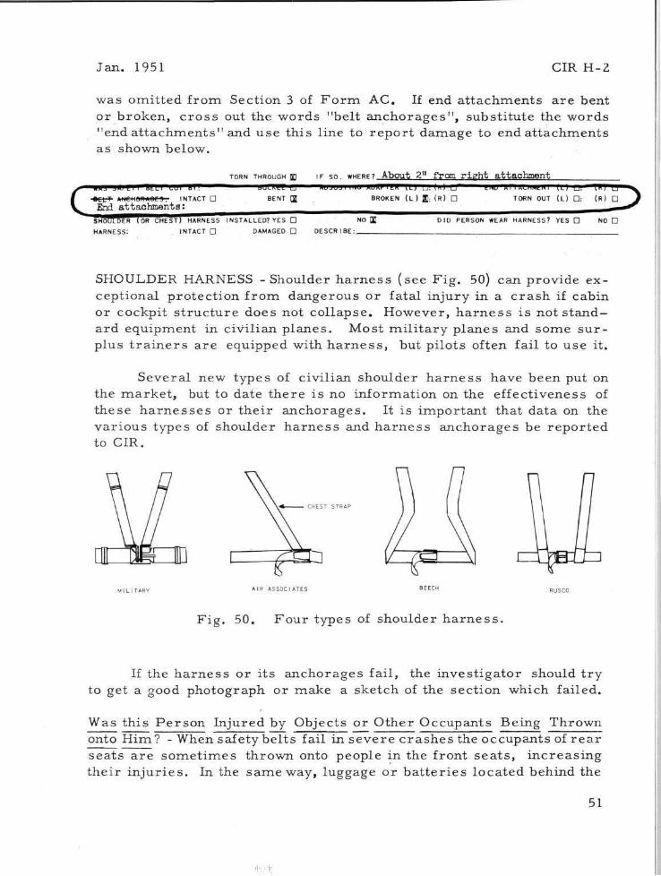
Jan. 1951 CIR H-2
was omitted from Section 3 of F o r m AC. If end at tachments a re bent or broken, c ros s out the words "belt anchorages" , substi tute the words "end a t tachments" and use this line to r epor t damage to end at tachments as shown below.
If the ha rnes s or i ts anchorages fail, the investigator should t r y to get a good photograph or make a sketch of the section which failed.
Was this Pe r son Injured by Objects or Other Occupants Being Thrown onto Him? - When safety bel ts fail in severe c ra shes the occupants of r e a r seats a re somet imes thrown onto people in the front sea t s , increas ing their in jur ies . In the same way, luggage or ba t t e r i e s located behind the
51
SHOULDER HARNESS -Shoulder h a r n e s s (see F ig . 50) can provide exceptional protect ion from dangerous or fatal injury in a c ra sh if cabin or cockpit s t ruc ture does not col lapse. However, h a r n e s s is not s t and ard equipment in civilian planes . Most mi l i t a ry planes and some su r plus t r a i n e r s a re equipped with h a r n e s s , but pilots often fail to use it.
Several new types of civilian shoulder ha rnes s have been put on the marke t , but to date there is no information on the effectiveness of these h a r n e s s e s or thei r anchorages . It is important that data on the var ious types of shoulder ha rnes s and h a r n e s s anchorages be repor ted to CIR.

CIR H-2 Jan . 1951
r e a r seat may be catapulted into the cabin. One civilian plane has a n auxil iary gas tank located jus t behind the pilot and passenger ; th i s tank occasionally comes loose in a c ra sh , causing injur ies to the backs or heads of the occupants.
Additional Information and/or Remarks : - The inves t iga tor ' s additional comments on dangerous cabin design, factors which provide or could provide g rea t e r c r a sh protect ion, and his recommendat ions for improve ments a re invaluable to engineers when modifying p resen t models or de signing new a i rc ra f t .
52

APPENDIX A CIR H-2
HOW TO FIND APPROXIMATE HEIGHT OF OBJECT.
1. HOLD CARD VERTICALLY AS SHOWN IN ILLUSTRATION ON INSIDE
OF BACK COVER: TILT CARD UP OR DOWN UNTIL 45° LINE IS
LEVEL.
2. WHILE HOLDING 45° LINE LEVEL, WALK TOWARD OR AWAY FROM
OBJECT UNTIL IT LINES UP WITH EDGE A-B OF CARD.
3. FROM THIS POINT. PACE OFF OR MEASURE DISTANCE TO BASE
OF OBJECT. A PACE (TWO STEPS) IS APPROXIMATELY 5 FEET.
4. ADD 5 FEET TO MEASURED (OR P A C E D ) DISTANCE TO GET AP
PROXIMATE HEIGHT OF OBJECT.
EXAMPLE (SEE ILLUSTRATION A B O V E ) : - THE MEASURED DISTANCE
FROM SIGHTING POINT TO BASE OF TREE IS 15 FEET.
1 5 FEET (MEASURED D I S T A N C E )
+ 5 FEET ( H E I G H T OF M A N ' S EYE ABOVE THE GROUND)
2 0 FEET = A P P R O X I M A T E H E I G H T OF DAMAGED AREA
ABOVE THE GROUND.

CIR H-2 Jan. 1951
APPENDIX B
HOW TO FIND APPROXIMATE FLIGHT PATH ANGLE (WHEN AIRCRAFT HAS STRUCK AND DAMAGED OBJECTS)
1. HOLD CARD AS INSTRUCTED (SEE INSIDE OF BACK COVER) AND
SIGHT ALONG EDGE OF CARD TOWARD OBJECT AT A POINT AP
PROXIMATELY 5 FEET ABOVE DAMAGED AREA.
2. WHILE HOLDING CARD AS DESCRIBED ABOVE, LOOK TOWARD
HORIZON AND READ NUMBER (DEGREES) ON WHICHEVER LINE
APPEARS TO BE LEVEL.
IN THIS E X A M P L E . THE 30° LINE IS L E V E L : T H E R E F O R E THE
A P P R O X I M A T E F L I G H T PATH ANGLE OF THE A I R P L A N E . AFTER
S T R I K I N G T H E T R E E . WAS 3 0 ° .
54

HOW TO USE SIGHTING DIAGRAM ON BACK COVER
(1) HOLD CARD VERTICALLY
(2) PLACE POINT (A) CLOSE TO INNER CORNER OF RIGHT EYE (NEAR NOSE)
(3) SIGHT ALONG EDGE A-B TOWARD OBJECT
(4) WHILE KEEPING OBJECT IN LINE WITH EDGE A-B. LOOK TOWARD HORIZON AND READ NUMBER (DEGREES) ON WHICH-EVER LINE APPEARS TO BE LEVEL.
(THE NUMBER READ IS THE ANGLE IN DEGREES OF THE OBJECT ABOVE THE HORIZON. FROM THE POINT AT WHICH THE "SIGHT" IS MADE.)

HOLD CARD VERTICALLY
PLACE POINT (A) CLOSE TO INNER CORNER OF RIGHT EYE (NEAR NOSE)
SIGHT ALONG EDGE A-B TOWARD OBJECT
WHILE KEEPING OBJECT IN LINE WITH EDGE A-B LOOK TOWARD HORIZON AND READ NUMBER (DEGREES) ON WHICHEVER LINE APPEARS TO BE LEVEL.
SIGHT ALONG THIS EDGE TOWARDS OBJECT B
BOTTOM