for air balij.st systems - defense technical ... air balij.st systems,np allen r. davidson, jr....
TRANSCRIPT
AFCRL-67-0679
FLIGHT CONTROL SYSTEMS AND LAUNCHING TECHNIQUESFOR
AIR BALIJ.ST SYSTEMS
,Np Allen R. Davidson, Jr.
VITRO LABORATORIES
Division of Vitro Corporation of America14000 Georgia Avenue
Silver Spring, Maryland 20910
"TECHNICAL NWYE 02057.02-2
Contract F19628-67-C-0192Project No. 6665
Task No. 666501Work Unit No. 66630101
Scienti'ic Report No. 26 November 1967
Distribution of this document is unlimited. It may be releasted to theClearinghouse, Lepartment of Commerce, for sale to the general public.
Contract Monitor: James F. DwyerAerospace Instrumentation "aboratory i
Prepared for
AIR FORCE CAMBRIDGE RESEARCH LA.SORATORIESOFFICE OF AEROSPACE RESEARCH
UNITED STATES AIR FORCEBEDFORD, MASSACHUSETTS 01730
C L f A P , I 0 U S

IiAFCRL-67-0679
FLIGHT CONTROL SYSTEMS AND LAUNCHING TECHNIQUESFOR
AIR BALLAST SYSTEMS
Alien R. Davidson, Jr.
VITRO LABORATORIES
Division of Vitrc Corporation of America14000 Georgia Avenue
Silver Spring, Maryland 20910
TE&.-:NICAL NOTE 02057.02-2
Contract F19628-67-C-0192Project No. 6665Task No. 666501Work Unit No. 66650101
Scientific Report No. 26 November 1967
Distribution of this docunent is unlimitea. It may be released to the
Clearinghouse, Depari-ment of Comumrce. for sale to the general public.
Contract Monitor: Jam.e= F. DwyerAerospace Instrumentation Labonitory
Prepared for
AIR FORCE CAMBRIDGE RESEARCH LABORATORIESOFFICE OF AEROSPACE RESEARCH
UNITED STATES AIR FORCEBEDFORD, MASSACHUSETTS 01730

I
ABSTI'ACT
This report examines bome of the more practical aspe--ts in theapplication of air ballast systems to the control of free-flight bal-loons. Each type of air ballast system, as defined in ScientificReport No. 1, is analyzed for the cost,, availability of materials,components, and instrumentation required. In addition 'for ectch typecf air ballast system deemed feasible, the possible flight sysx-emcontiglratinons, vosociated launching problems, and methods to solvethe problems aree investigated. It is the conclusion of this reportthat most air ballast systems can be instrumented and flown with con -ventionsml or ofif-the-shelf components and equipment. Systems u-.ngvery large~ payloads are more difficult to handle and launch thansmaller payload systems and probably will require some development innew launching techniques and associated equipment.
I!
iii

TABLE OF COGNTETS
Page
Abstract . . . . . . . . . . . . . . . . . . . . . . . . . . .
Contents . . . . . . . . . . . . . . . . . . . . . . . . . . .
Illustrations . ...... . .... ... .. . ... . . . v
Tables . . Vil
Se tion
I Introduction .................... 1-1
A. Mass Fa.xulsion Ballast System ........ . 1-1
B. Sealed Cell Ballast ';ystem .............. .... 1-2
C. Powered Air Ballast System !.................1.2
D. Capabilities of Air Ballast Systems .... ...... 1-3
II Flight Control Systems ..... ............... .... 2-2
A. Test and Design Evaluation InstrumentationRequirements ...... ................. .... 2-1
B. Monitoring and Control InstrumentationRequirements ................ 2-5
C. Rcoairerients Summary .......... .............. 2-6
D. Instrumentation. ....... ................ ... 2-!i
E. Ballast Bag Valves . . ....... .. . . 2-16
III Flight System Configurationz. ..... ............ 3-1
A. General ................... . 3-1
B. Air-Filled Mass Expulsion and Sealed Cell AirBallast Systems ......... ............... 3-3
C. Helium-Filled Sealed Cell Ballast Systems . . 3-12
D. Powered Ballast S:;stems ..... ............ ... 3-25
IV Conclusions ................ ................... 4-i
iii

I!I!TArL, Ti, OF CONTENTS", (Cor~tin;ued)
PageApuen,• ix
Deternir.:ttion of Exhmu:ting Time for PressurizcdSpŽheres witr Circular Orifices .......... A-I
B. Determination of Exhaust Requirements forAscending Scaled Cell Systems ... ............. B-i
C. Deter-mrination of Largest Bubble that can beHandled by a 40-Foot Boom Crane ..... ......... C+I i
Glossary .................................... Gloss-i
ii
4
iv
LIDT OF ILLUSTIIATIONS
FiturePage
2-1 Block Diagram of Ballast 'ysten Telemetry System , 2-15
3-1 Typical Load Configla-tion on Spherical Super-pressure Balloons ............ ................. 3-1
3-2 Flight Configuration for Air-Filled Ballast BagFlight System ........ .. ................... 33
3-3 Tyical Inflation Configuration of Single CellPoly Balloons ........ ..... ................... 3-5
3-,'- inflatio~i of Ballast Bag with Air 3-7
3-5 Handling of Air-Filled Ba1 ] .st Bag during InflationSof Main Balloon .. , I.......I..oi anBlon..........................3-8
3-6 Static Launch Configuration f0. Large Air-FitledBallast Bags ....... ..... ................ 3-
3-7 Inflation Configuration for Large Air-Filled BallastBag Suspended A:ive Payload ............ 3-L_
3-8 Helium-Filled S 'ell Ballast System FlightConfiguratior ........ ....... ................ 3-13
3-9 Launch Configaratioa3 for Ballast Bag Filled withHel.ium ...... ......... .......................... 3-16
3-10 Initial Inflation Pha-te (Ballast Bag Filled withHelium).... .. . ...... ....... 3-L7
3 -1I1 AFCJRL Clutch Launcheir Holding Down a SuperpressureBalloon ........... * .......... .... 3-16
3-12 Configuration of Ballast Bag Filled with HeliunBefore Erection of Flight Trai-n ..... . . ... -
3-13 inflation Configuration of Ballast Bag Filled withHelium with Short Suspension Tapes .... ........ 3-20
3-14 inflation Configuration of High Lift Ballast Bal; . 3-1
3-05 Helium-Filled Sealed Cell Ballast Bag Slung UnderPayload I .......... ... ...................... 3-22

LI;/' OF ILLUSTRA'IIONS (Conitinucd)
SFiourc Page
3-16 Tandem Balloon Configuration for 31rperpressureBallast Bag on Top of Zero Pressure Balloon . . . . 3-24
3--17 Flight Configuration of a Powered Mass ExpulsionBallast System ..... ............... .... 3-26
3-18 Flight Configuration of a High Net Lift Winch PoweredHelium-Filled Sealed Cell Ballast System ..... ... 3-27
3-19 Flight Configuration of a Low Net Lift Winch PoweredHelium-Filled Ballast System ........... . . . 3-28
A-I Pressurized Sphere with Circular Orifice ...... .. A-I
C-I Determination of Maximum Size Bubble with 40-FootBocm Crane . . ................... C-I
C-2 Example of Maximum Bubble Size .... .......... ... C-3
vi

LIST OF TABLE
Table Page
1-! Payload Capabilities of an Air-Filled Ballast System . 1-4
1-2 Payload Capabilities of -i Helium-Filled BallastSystem . . . . . . . . . . . . . . . . . . . . . . . 1-4
2-I Measuring Instrumentation Requirerxnts. ........ 2-7
2-92 Ballast Bag Valve Orifice Sizes for Mass ExpulsionAir Ballast Systems ................ 2-17
2-3 Relief Valve Orifice Sizes for Ascending Ballast Bags. 2-18
3-1 Launch Restrictions for a 40-Foot Boan Crane ...... 3-8
3-2 Mininum Size Ballast Bag Radii for Helium-FilledSealed t.Cell Ballast Systems . . . ......... 3-15
4-
F vi
ivi
ImJ

I
Scction I
IITRODUCTION
This report is a result of a study of various flight control systemsand associated instrmnentation and launching techniques for air ballastsystems. Th'*s is the spcond report relating to air ballast systems. InScientific Report No. 1; 'ir ballast systems are classified in.c threegroups. Within each group are a variety of system configurations. Eachconfiguration, however, works on the same principle; that is chnging the
displacement weight of the ballast system to c .pensate for sunset andsunrise effects on a zero-pressure balloon. The first two groups requirelittle or no external powei to operate except for that necessary tooperate monitoring instrumentation and the uallast valve. The threegroups are:
1. Mass expulsion ballast systems.
2. Sealed cell ballast systems.
3. Powered air ballast systems.
A. MASS EXPUSiION BALLAST SYSTEM
The mass expulsion ballast system operates like the conventionalpourable solid ballast systems. This system carries a mass of air orsuitable gas within a superpressture balloon, or ballast bag, to a pre-determined daytime operating altitude, at which the gas is under pressureand has a higher density than the outside atmosphere. When sunset occxrs,the balloon begins to lose lift due to "sunset effect". At this time, aballast gas valv2 is opened and the air or gas within the bag is allowedto escape. The density of the air or gas within the bag decreases, thusdecreasing its displacement weight. If the bag is properly designed andthe p,'oper mass of gas is inside the bag during the day, -)hen when theair or gas escapes, the displacement weight of the bag will dtcrease bythe same amount as the ±ift that was lost due to sunset effect. Once thegas is expelled from the ballast bag, the mass expulsion systen can nolonger operate as a ballast systeam unless the bag can be refilled againthe next day.
tScientific Report No. 1, A Survey of Methods for Controlling the Altitude
of F.ree Balloons with Air Ballast Systems, Air Force Cambridge ResearchLaboratories, Office of Aerospace Research, USA!,, Bedford, Massachusetts,September 29, 1967.
1-1

B. SEALED CELL BALLAST SYSTEM
The sealed cell ballast cy.rtem, like the mass expulsion system, con-
sists of a bag of pressurized air or gas carried aloft with the main balloonto operaticnal altitude during the day. When sunset effect occurs on themain balloon, rather than let the gas escape from the bag, the whole balloonsystem descends as lift loss is experienced on the main balloon. While thesystem is descending, the density of the outside atmosphere increases, thusdecreasing the differential pressure on the ballast bag. If the gas insidethe bag is air, the displacement weight of the ballast system decreases asdifferential pressure decreases. If the gas is helium, the gross lift ofthe ballast bag will increase as the differential pressure decreases. Witha properly designed ballast system, the balloon system will level out at analtitude where the differential pressure on the ballast bag drops to zero.At this point, the decrease in displacem-nt weight (air-filled bags) or in-creases in gross lift (helium-filled bags) of the ballast system willcompensate the total lift loss due to sunset cffect. Unlike the mass ex-pulsion system, the sealed cell ballast system can theoretically operateindefinitely provided the main balloon does not leak helium and theballast bag does not lose ballasting capability due to gas leakage.
T th. .caled cell air ballast system can allow a balloon system
to stay up indefinitely, if the range over which the system travels fromday to night is outside the mission objective of the instrument payload, itis necessary to consider the use of the third group of ballast systems.
C. POWED AIR BALLAST SYSTEM
The fumction of a powered air ballast system is to accumulate powerduring the day (usually frc. the sun), compensate for sunset effect, andutilize stored power during the next morning to re-ballast the balloonsystem during the sunrise effect.
Within the powered air ballast system group are two basic configura-tions. The first uses an air compressor on a mass expulsion ballast systemto compress outside air into the ballast bag during the morning while solarradiation from the sun superheats the lifting gas in the main balloon. Asthe lifting gas is superheated, and the lift of the main balloon increases,the outside air is compressed into the ballast bag, thereby increasing thedisplacement weight of the air ballast system. The total increase in liftof the main balloon due to superheat is therefore ccmpensated by the totalincrease in displacement weight of the ballast bag when fully pressurizedby the air compressor. During the day, solar cells convert solar radiationto electrical energy to charge the batterieZ in the ballast system. Thebatteries provide power to the air compressor during the eriod of the sun-rise effect. This type of powered air ballast system ca maintain theentire balloon system at nearly constant altitude indefinitely. Its flightduration capability is limited only by the permanent loss of lift due toleakage of gas from the main balloon and the cyclic capability of the powersystem.
1 -2

jf
The .- cond iyvpe of powered air ballast system consists of a -;ealedc•'!l ballast .Jtem on a powered winch. Instead of allowing the entireb1:loon sysrtem to descend at night to compensate for sunset effect, thew-inch lowers the sealed cell ballast bag while the main balloon with itsinstrwner.t payload rel.iins at constant altitude. The power cycle forthis system is essentially the same as the powered mass expulsion system.11Cgain, the flight duration capability is indefinite, except now it is1L!niited by leakage of gas fron the ballast bap as well as from the mainballoon. Notice that in the powered mass expulsion system, any leakagefrom the ballast bag can be compensated by the air compressor on the bag.
D. CAPAP!LITIES OF AIR BXU-1AST SYT-US
The gross lift and the a'mount of sunset effect, on the zero-pressuremain balloon governs the ballasting requirements from the air ballastsystem. The capacity of the air ballast system, in turn, depends on thevolume of the ballast bag and on the c.aracterisitcs of the ballast bagmaterial; that is, superneaT 'efec, weIght, streng-th, and elasticity.As noted in Report No. 1, bag fabric characteristics li-mit not only thecapabilities of a particular size air ballast system but also the sizeof the sstem. For each set of bag fabric characteristics, there existsa maximum or optinun size bag for a given set of operating conditions.if the ballast bag is -ade any larger than this maxi•um or optimum size,the payload capability of the uwhole system is decreased, or else theballast bag can not structurally withstand the pressures attributed tosuperheating, much less the pressures required to achieve air ballast.This m~aximum or oDt•- izr the
T o turn size of the ballast bag which li-its the payloadcapability of the balloon system, in turn is dependent not only on thefabric characteristic of the ballast bag but also on the fabric in themnain balloon.
The payload capahritaies of trie air-filled mass expulsion and sealedcell air ballast systems are the same. it was found that, for increasingoperational altitudes, the •otinun size of the bags increased as well asthe payload capabilities of the system. Table 1-1 shows examples wherepayload capabi ... ie.e were determined for an air-filled 2-mi!l Mylar ballastS bae carried by a 2-mi- Polyethylene zero-pressure main balloon. The sun-s efet o '-. balboon a st " ••et effect on man .al.oon and baa bag s assumed to be 10 percent.
The payload capabnilities of he'-eum-filled sealed cell ballast systemsare higher than air-filled zystems because of the added lift from theallast,- ba. it was noticed, however, that operational altitudes have ar siaer eect on tapabilities. It was also found that thereis no optimum bag size but rather a maximum bag size for which the helium-filled sealed cell system can be made. At this maximum size, the bag canonly w-'ithstand diffý a-rcntial pressures due to its own superheat during the
EL

TABUL i-i. PAILO;IU UAP.bLAT) VV ACA AL-_ a±LT )T BA L T 7Y`T__-
Daytime tium Volume of Maxiu.m payload (includesoperation bag size main Wt. of instruments & ancillaryaltitude radius balloon equipment of ballast system,
(ft., (ft.) (cu. ft.) but not bag Wt.) (pounds)
60K 15 15K 1(.4
70K 25 75K 51.2
80K 35 265K 110.0
90K 50 850K 217.0
day; that is the ballast system flies by itself as a superpressure balloon.Table 1-2 lists some payload capabilities of helium-filled systems. These
can be compared with the same ballast systems and assumptions made for theair-filled system.
TABLE 1-2. PAYLOAD CAPABILITIES OF A HELIVM-FILLED BALLAST SYSTEM
I IDa3-time Bag Payload Maximum Maximumoperating size (less bag size payloadaltitude radius bag weight) radius (less bag
(ft.) (lb.) (ft.) weight) (lb.)
60K 1 80 33 776
70K' 25 26o 4 1428
80K 35 620 78.5 3852
90K 50 990 125.0 9582
j~l
I
'.~ctlio ii
FL"IdT CO!TN'IOL SYSTW1S
A. TEST AD DESIGN EVALU/ATION INSTRUMENATION REQUIPOENTS
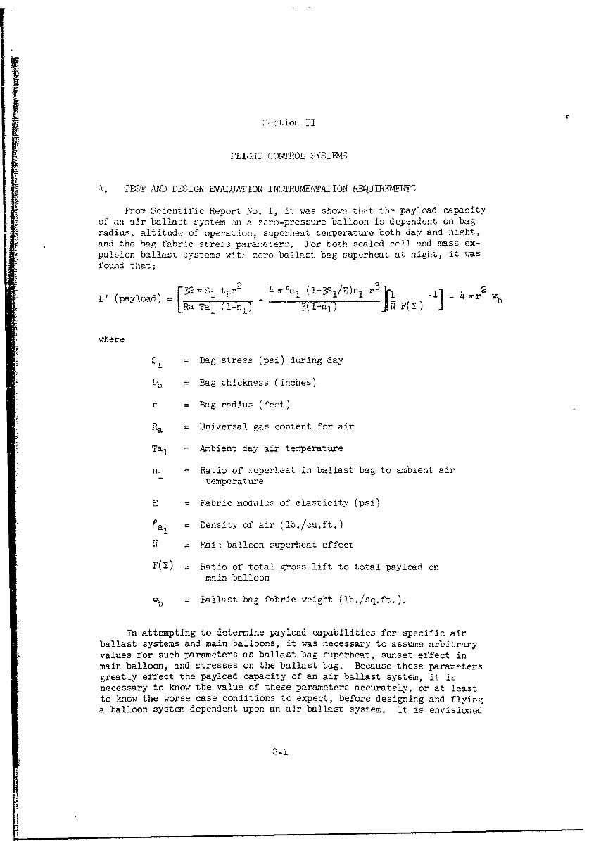
From Scientific Report No. 1 i, was shown thtat the payload capacityof an air ballaSt system on a zero-pressure balloon is dependent on bag
radius. altitude of operation, superheat temperature both day and night,and the bag fabric streLs oarap.et-e. For both sealed cell and mass ex-pulsion ballast systems with zero ballast bag superheat at night, it wasfound that:
[32r zS tr - 4 - Pa, (!-3S!/E)n l r3 J 4 -1i] _ 2 bL' (paylo-ad) 4 rWb
lRa Tal (ln!) 3(7+nI) 17F() J
where
= Bag stress (psi) during day
tb = Bag thickness (inches)
r = Bag radius (feet)
Ra = Universal gas content for air
Tal = Ambient day air temperature
nI = Ratio of superheat in ballast bag to amrbient airtemperatiure
E = Fabric modulus of elasticity (psi)
P a, = Density of air (lb./cu.ft.)
N =1i Mi balloon superheat effect
F(M) Ratio of total gross lift to total pay-oad onmain balloon
wb = Ballast bag fabric weight (lb./sq.ft.).
In attempting to determine payload capabilities for specific airballast systems and main balloons, it was necessary to assume arbitraryvalues for such parameters as ballast bag superheat, sunset effect inmain balloon, and stresses on the ballast bag. Because these parametersgreatly effect the payload capacity of an air ballast system, it isnecessary to know the value of these parameters accurately, or at leastto know the worse case conditions to expect, before designing and flyinga balloon system, dependent upon an air ballast system. It is envisioned
2-1
U

therefort: tL"" ,,< -. , carryingr air ballast- LyLtem, L will be flol?it,• -1 "'h.i6ý_/ back" t',, . : itth bailoon-s containint" conventional droppable
ba 11haý-t .
Tri-ý_ conivent-;onal iropmat,]t, ballaý_t will augment the air baila..,t so that
sunet effect on th, "nai:., taloon will be compensated completely. This"piggy bac.K"' sy .. wi~ l atlow for heavier payloads, and consequently amore mobiclel and highly inctrumentel flight which can be positively control-
led and monitored. Theýrefore, it will bt possible to obtain more accurateand realistio value. for TAe desin and ight of those balloon systems thatdepend solely on the ballast available from an air ballast system.
Examination of tLe payload formula reveals the terms which need to be de-termined from instrrenteu flights. Terms such as bag radius, (r), bagmaterial thickness (t), and Tain balloon payload to gross lift ratio F(-) are
determined by design, and can be ascertained by measurements and qualitycontrol in fabrication. Bag fabric modulus of elasticity (E) can be deter-
mined fairly accurately under iaboratory conditions for the temperatures
expected at operating altitudes.
Fabric stress (SI) determines the amount of pressure the bag contains.Strain gages can measure this stress directly. However, strain gages are dif-ficult to mount en flimsy balloon fabric, and at best, would set up localstresses and constrictions which could produce iPaccurae results. It is feltthat measurement of differential pressure ( a P) wil produce more accurate
data. Fabric stress can be determined mathematically from AP by the followingfoi.rmula derived in Report No. 1:
24 st"Ap =
r (1-3SiTE)
Since a P is uniform throughout the oallast bag, the differential transducermay be mounted wherever convenient, preferably near the instrument packagepayload. However, the transducer should be located away from the ballastvalve, lest local turbalerce and partial pressure drops created by the gasescaping through the valve disturb the readings.
Superheat in the main balloon and the ballast bag has a great effect or,the ballast system. it 1c necessary to accurately determine both internaltemperatures of the rain balloon and ballast bag and the ambient air tempera-ture. Ambient air temperature can be determined fairly easily from atemperature probe, such as a thermistor bead, suspended away from the paylCadand shielded from. radiation fran. the earth, the sun, and the balloon systemitself, A successful method for .neasuring ambient air temperature is to use
all bead tthermistor suspended on a line a few hundred feet below the__ight train.
fLittle, A.D. Report No. V, The Measurement of High Altitude Balloon GasTemperature, R. 3.4. lucas Pnd G. 11. Hall, October 1966.
2-2
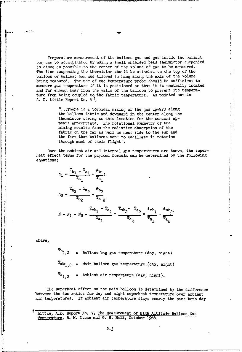
Tcmpcrature mcasurcmcnt of the balloon gas and gas inside the bLllastbag can be accanpl`shed by using a small shielded bead thermictor suzpendedas close as possible to the center of the volume of gas to be measured.The line suspending the thermistor sho- Id be attached to the top of theballoon or ballast bag and allowed tj hang along the axis of the volumebeing measured. The usr! of one temperature probe should be sufficient tomeasure gas temperature if it is positioned so that it is centrally locatedand far enough away from the walls of the balloon to prevent its tempera-ture from being coupled to the fabric temperature. As pointed out inA. D. Little Repcrt No. V1,
"..There is a toroidal mixing of the gas upward alongthe balloon fabric and downward in the center along thethermistor string so this location for the sensors ap-pears appropriate. The rotational symmetry of themixing results from the radiative absorption of thefabric on the far as well as near side to the sun andthe fact that balloons tend to oscillate in rotationthrough much of their flight "'.
Once the ambient air and internal gas temperattires are known, the super-heat effect terms for the payload formula can be determined by the followingequations:
-b T 61
nI Tb - al= Obl.
TalrTa1 a--1 '
Tb2 Ta2 b2n2,, _Ta 2 Ta 2
Tmb -Ta, Tmb T a22 mb 6 rmb2N- N1- N2 1 l 2 e 1
Ta Ta Tal Ta2
j where,
Tbl,2 = Ballast bag gas temperature (day, night)
Tmbl, 2 = Main balloon gas temperature (day, night)
Tal, 2 = Ambient air temperature (day, night).
The superheat effect on the main balloon is determined by the differencebetween the two ratios for day and night superheat teumerature over ambientair temperatures. If ambient air temperature stays r:eariy the pame both day
t Little, A.D. Report No. V, The Measurement of High Altituje Balloon GasSemverature, R. M. Lucas and G. H. Hall, October 1966.
2-3

and nijht, tien
N mb - mbON 1 2
Tal
The last term to be measured for the payload formula is air density(Pa), which can be determined fram the perfect gas law once ambient airpressure and temperature are found. Therefore, a pressure transducer mustbe carried that not only provides altitude information, but also the dif-ferenial air pressure experienced on Lhe ballast bag. Accordingly, thepressure transducer should be located as near to the ballast bag as possiblein order to obtain local air conditions around the ballast system.
As a general check on the payload formula and the values of the datataken frnm the measurements, it is necessary to dete.-mine the weight of airballast taken on or released by the ballast system. For air filled systemsthis can best be accomplished by use of a strain gage cr load cell whichcontinuously monitors the displacement weight of the ballast bag, The dif-ference between the measured displacemert weight and the uninflated weightof the ballast bag provides the weight (A) of the air bllast in the bag.This value for A can then be ccmpared with the other measured values throughthe following formula derived for air ballast weight in Scientific ReportNo. 1:
A 4r 3 (I-3S!/E)[P'l + nI 1]3 RA T (1+n a
where
A = Air ballast weight (lb.)
Pa = Ambient air pressure
APl= Differential pressure in ballast bag
For helium-filled sealed cell systems, the effective air ballast weight(Aeff) can be measured by determining the difference between the day andnight lifts of the ballast bag. In this case, the load cell or strain gagemeasures the lift exerted by the ballast bag. The difference between tneday and night lift is related to the other measured values by the followingformula, also derived in Scientific Report No. 1:
,32 7r2 r +n2 )Sltb 4 rr3 pal (n2 - n9(1+31 /E)- b -RA T (.+nI) . (l+n 1 )
2-4
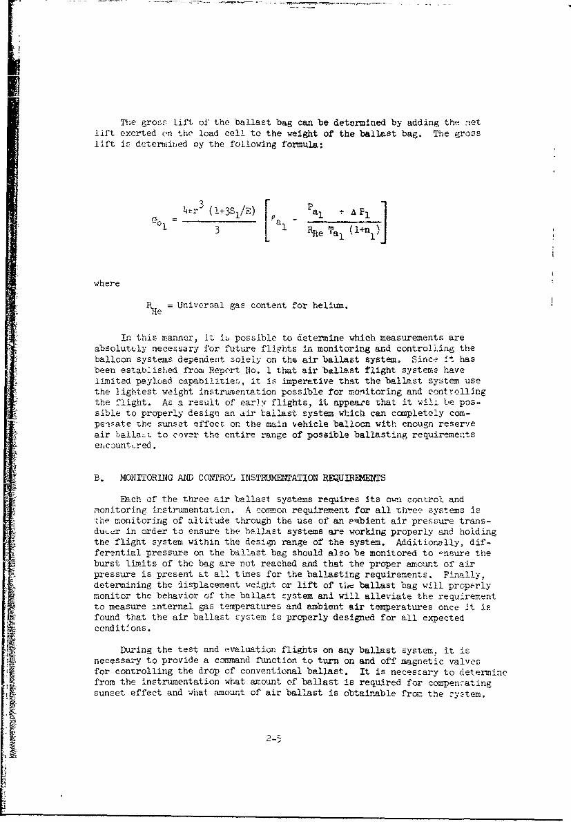
The gross lift of' the ballast bag can be determined by adding the netlift exerted en the load cel! to the weight of the ballast bag. The grosslif• is detenrmined oy the following formula:
~ l3S/) a ±A ( 1[ai R*r 1 (+n 1 )e~i= 4r•(!÷Si/)3'°a "Rhe Tal I'
where
e Universal gas content for helium.
In this manner, it i• possible to determine which measurements areabsolutely necessary for future flights in monitoring and controlling theballoon systems dependent solely on the air ballast system. Since it hasbeen established from Repert No. 1 that air ballast flight systems havelimited payload capabilitie.s, it is imperative that the ballast system usethe lightest weight- instrumentation possible for monlitoring and controllingthe flight. As a result of early flights, it appears -hat it wilL be pos-sible to properly design an air ballast system which can completely com-pe-i~ate the sunset effect on the main vehicle balloon with enougn reserveair ballasL to cover the entire range of possible ballasting requirementsencounttred.
B. MONITORING AND CONTROLr INSTRUMENTATION REQUIR•4ENTS
*Each of the three air ballast systems requires its owni control andmonitoring instrumentation. A common requirement for all three systems isthe monitoring of altitude through the use of an embient air pressure trans-ducer in order to ensure the ballast systems are working properly and holdingthe flight system within the design range of the system. Additiornlly, dif-ferentiai pressure on the ballast bag should also be monitored to -nsure theburst limits of the bag are not reached and that the proper amount of airpressure is present, at all times for the ballasting requirements. Finally,determining the displacement weight or lift of thiI ballast bag will properlymonitor the behavior of the ballast system and will alleviate the requirementto measure internal gas temperatures and ambient air temperatures once it isfound that the air ballast system is properly designed for all expectedconditfons.
Du-ing the test and evaluation flights on any ballast system, it isnecessary to provide a coimnand function to turn on and off magnetic valvesfor controlling the drop of conventional ballast. It is necessary to determinefrom the instrumentation what amount of ballast is required for compenzatingsunset effect and what amount of air ballast is obtainable fron the cystem.

The rwts2 expulsion air ballast system requires a valve to allow thepressurized air in the ballast bag to escape in order to compensate thesunset effect on the main balloon. Therefore, a control function will berequired in the instrument pacikage to couand the valve to open and close,o allow proper discrete amrounts of air to be released from the ballast
bag. Since large quantities of air need to be released, and in the intere.stof keeping the balla-t valve as light as possible, it may be necessary tohave a time lag between the time of the command to open or close the valveand the time when t:-e valve responds. Therefore, in the test and evaluationflights, it may be necessary to monitor the position of the air valve sothat the time lag for warious altitudes and pressuresare kno'wn in advance.In this manLner it is possible to eliminate instrumentation and associatedhardware for monitoring the position of the valve during solo flights."Solo" flights axe defined as flights that depend solely on the ballastavailable from the air ballast system.
The sealed cell ballast system ideally needs no control instrumentationsince the ballasting obtained from the system is determined by design andflight conditions. However, since it is difficult to insert the exactamount of air or helium into the ballast bag while on the ground, it is ex-pected that normal operational procedt-ies will require that an excess amountof air or helium be inserted into the ballast bag at launch and then be re-leased by a relief valve while the flight system ascends to design altitude.This relief valve may be either electrical or mechanical, but must be ableto keep the pressure in the ballast bag within a fairly close tolerance.For the test and evaluation flights, it may be desirable to -have a combi-nation of a relief valve and a ballast valve, such as one which might beused for the mass expulsion system. The relief valve can then be evaluatedfor accuracy control, and at the same time allow for positive control ofthe pressure in the ballast bag in the event the relief valve malfunctions.
The powered air ballast systems require the same instrumentation as thesealed cell and mass expulsion systems and additionally require control in-strumentation for the power units themselves. A means for orientating thesclar cells to the sun during the day and regulating the charging voltageto the batteries must be provided to ensure the proper amount of power isavailable to compress air ballast or haul up the ballast bag during the sun-rise effect period. For the 2-cycle mass expulsion system, a commandfunction must be provided to turn on and off the air compressor. Built intothe compressor unit should be a back-pressure valve so that pressure builtup in the ballast bag is retained when toe compressor is shut off. For thewinch controlled sealed cell ballast system, we need two command functions,one to turn on the electric motor and the second to engage or disengage theclutch on the winch to allow the ballast bag to be hauled up and lowered.
C. IREWUMMS SI0UMARY
The specific requirements necessary for each type of ballast system arelisted below. The requirements are in two groups: measuring instrumenta-tion requirements that are necessary for all ballast systems, sed controlfunction and instrumentation requirements that pertain to specific airballast systems.
2-6

II
D' .. , .- ,~ T 4-..n Table .r. .. .... f'T
ir ,;allat y.,:: ar i. i,-d below. Table 2-! lizts specific requircments.
In.-trui•r-i.it i xi-P it no dr4ft or leos of accuracy afterrepeated temperaturv and pre1.Žcure cycling, a:.,i after expos;ure to solarradiation.
2. Instrinent. Thall be unaffected by sc-rar radiatio:i, and whencoiin-,ced to intrumnent leads, shall be insensitive to !, (roa .etic ra-diation, local turbuicnce.•, rnd other interference factors associated witht,,.-o bailoon :uy:tem.
S. Inmtrunentz shall be small, lightweight, and capable of being
*hyi cnly prot.eted during flight. This is particularly important for
temperature :urenent: witj thern i3tor beads.
STABLE 3-T. I TJ.U , M fl=Rbf4NTATION REQUIR FS
ResponseFunction Range Accuracy Time( :ec.) Resolution
Main balloon gas 3-70R to -!R 1/4 0F
0° ±!/20F ! to 52 4temperature
Ballast, bag -370°R tc LW0R =-!/20F ! to 5 ±i/4°F
temperature
SAmbient air 370°R to 4ý20°R ±1/20F 10 to 20 -1!/4°F
temperature
Ambient air 1013 tc _e :2. mb I to 3 ±1/2 mb
Spressure (entire flight)
(oper. altitude)
Differential 0 to 54 mb :" mb 1 to 3 -1/2 mbpressure on ballastbag (8' radius)
Differential 0 to 0 mb ±0.2 mb 15 to 20 ±0.1 11pressure on rallast",bag (50' radius)
Ballast bag weight* (Wb-lO: Aeff) to ±11 of I to 20 ±50% of
(Wb+i 0% Aeff) : range (depends accuracyair filled on bag rqts.
(G 1b, lq'DCf Ae ff) size)
to (Gb I-Wb.l
________________ A Aff-): ieliux
fi•l•led
*Examples of ballast bag weight using the indicated requirement. are given
on the following page.
HE

Example I - 8-foot radius, 2-mil Mylar, air-filled bag at 70,000 feet
Aef f 4.5) lb.
Bag weight (Wb) = 18.0 lb.
Range = 17.5 Lo 2D.9 lb.
Accuracy ±0.06 lb. (± 1 oz.)
Response time = 1 to 3 sec.
Resolution = zO.03 lb. (± 1/2 oz.)
Example 2 - 25-foot radius, 2-mil Mylar, air-filled bag at 80,000 feet
Aeff = 36.6 lb.
Bag weight = 115 lb.
Range = 1ll to 1'5.5 11.
Accuracy = zo.45 lb. (± 7 oz.)
Response time = 10 to 12 sec.
Resolution = ±0.23 lb. (± 3.5 oz.)
All the requirements in Table 2-1 are necessary for "piggy-back" flights.The ambient air pressure and differential pressure on ballast bag are the min-imium necessary for solo flights.
Control Function and Instrumentation Requirements - The general require-ments for control functions and instruments are:
1. All control and power units must survive 30 days flight opera-tions at operating altitude and within the following ranges:
Temperature - 360OR to 420°R
Pressure - 120 to 10 rb
Relative humidity - 0 to 100%
Solar radiation - Intensity expected at 50,000 to 100:000feet altitude
2. Instruments shall be .al,_,- lightweight, and capable of survivingshocks associated with launching and ascent.
3. Instruments shall be properly shielded fran flight-train instru-mentation to prevent interference to monitoring equipment.
2-8

I
4. InItrument'L hall require r.Lnimutm power to operate and stillmeet Zpeci1ricat ons •n order to redu2, -,eigbt cf batteries and associatedpow'r s"y.,toir ..
During test and evaluation "piggy-back" flights, it is necessary toiiave a control function to operate magnetic ballast valves to discharge con-ventional ballictt. Ideally, a properly designed air ballast system requiresno conventional solid ballast. lhuwever for purposes of ascent and descentcontrol, as well a: cou.persation for Cas leaks, it prObably will be necessaryto carry some converntioral :olid ballast during dummy solo flights.
Below are listed the control and instrumentation requirements necessaryfor a particular type air ballast ,-y:tem.
I. Mass expulýion ballast syrtem
(a) Air ballast valve (varies with bag size)
Orifico .i~e - muc't allow bag to go from full superpressureto zero pressure in 30 minutes.
Maximum pressure -to UO mr
Leakage 0.1 cu~ft./hr. at 30 nb
Operation - electrical cor2n.ana, full open to full close in10 seconds, full close to full open less than7 cocondZ.
Power - DC, 36 watts btarting, 12 watts running.
2. Sealed cell systemn
(a) Relie' vslve (varies with bag size)
Orifice size - must allcw air to escape to maintain constantpressure on ballý--t bag while ascending 1,000ft./min. between 20,000 and 90,000 ftht.
Maxtm.num *ressure - - to 60 nb
Leakage - 0.1 cu.ft./hr. at 30 mb
Oyeration - electrical command, re.ote (optional), self regu-lating (mechanical desirable), full open to closeless than 2 seconds, full close to open iecs than
second.
Regulation setting range - 6 to 60 mb
opening tolerance - 2 mb from setting
closing tolerance - 0 mo from setting!
response tJine - 2 sec. open to .... o3 sec. •-lose to op.;
;.2•C_

Iirepeatability - -0.5 rib
power requirements - DC, 36 watts for electrical control valves;spring, hydraulic for mechanical.
3. Powered 2-cycle mass e;ulsion system (compressor)
(a) Air ballast valve - same as l(a.)
(b) Power system
Solar -ell orientation - cells should receive 90 percent ofsunlight cnergy for 10 hr./day.
Power regulation - t2 volts of battery charging voltage.Must detect and stop charging when batteries are fullycharged.
Power output - operate all instruments continuously. Mustbe able to compress ballast bag at least once every24 hours.
Duration of operation - 30 days.
(c) Compressor
Control - zurn compressois on and off by remote command atleast five times during compression cycle of 1 hour.
Operation - must be able to fill bag within 1 hour atoperational altitude, and start and stop at least fivetimes during 1 hour compression cycle.
Back pressure - range: 9 to 60 nob, leakage less than0.1 cu.ft./hr. at 30 mb.
Efficiency (motor and compressor) - at least 40% total ef-ficiency; electrical efficiency 5q•, adiabatic compressoreffici ency 8C%.
Volumetr'- compression - capacity-to-weight ratio - 20 cu.ft./rain./lb. 'compressor and motor total weight) at operationalaltitude.
4. Fowered sealed cell system (winch).
(a) Relief valve - same as 2(a).
(b) Poa'er system - same as 3(b), except main power switch is tewinch controls.
(c) Winch -
Control fThnctions - turn winch on and off remotely at leastfive times while ballast bag is rising during sunriseeffect (I hour). Eigge and disengage clutch to winch atleast 20 times while ballast bag Js r-aised or low-ered.
2-ic0
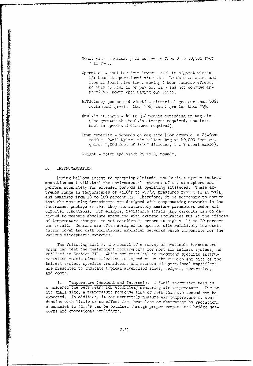
Monit rin,; - m,-azuw, pa:id out cav -.,- lrc: 0 to £0, 000 f,-tet, ) fe, ,t.
Oncration - saul 1a,- fron lowest icvel to highest withinif'2 hour -it crat,.on.. a1L*ttde. Be able to -tart and
stop ta.v t during a hcau" sujrise effect.
Be able to haull i. or Day out linc! nd not cons•ne an-;reci'.ble power when paying out caule.
ienc .... ("motor a.d winch) electrical greater than 50%;.. c.,rnanic: 1. creat r t..an YY, totaI greater than 45.
Haul-in s•t 2nC:th - 40 to 300 pounds depending on bag size(thie greater the haul-in strength required, the lesshaul-in speed and distance reaiired).
Drum capacity - depends on bag size (for example, a 25-footradius, 2-il. Mylar. air ballast bag at 80.000 feet re-quires •,000 feet of !/" diameter, 1 x 7 steel cable)
Weight - motor and winch 25 to 35 pounds.
D. DIST.I=E1. ATiON
During balloon ascent to operating altitude, the - tsyrt-e instru-mentation must withstand the environmental extremes of tnL atmosphere andp'erform, accurately for extended nerýods at operating altitudes. These ex-tremes range in temperatures of +110°F to -90'F, pressures frnn 0 to 15 psia,and humidity fran 10 to 100 percent RH. Therefore, it is necessary to ensurethat the measuring transducers are designed with compensating networks in theinstr•ument package so zhat they can accurately measure parameters under allexr0ected conditions. -,*or exam.ple, resistance s-train gage circuits can be de-signed to measure absclute pressures with extreme accuracies but if the effectsof temperature changes are not considered, errors as high as 15 to 20 percentcar result. Sensors are often designed to operate with relatively low exci-tation nower and with opcrational anmplifier networks which compensate for theva ious-, atmoSpheri c extremes.
The following list 4s the result of a sur'vey of available transducersw-hic can meet tne measurcment r.• . .. .. for -most air ballast systems, asoutlined in Section IIC. While not Practical to recamr.end specific instru-non-ation ,c.el.s since . election is dlependent the mirssion and size of theballast syrteI,, specific Tr ansducerz and asscciate3 oer.- ona. am=!ifiersare 7resEnte-d to indicate ty.:._pical adovi,-Sed sizes, weighs," ascuracIes,and costs.
1. Temperature (A.bient, and int-ernal A 5-:4I t- e=7tor bead ,sconsidered the best meart for accurately measuring air t•enperature. Due toits small size, a temperature resnonse time of >'ess than 0.5 second can beexpected. In addition, it caz accurately measure air tennerature by con-duction with little or no effect f•rn heat loss or absorption by radiation.Accuracies to --0.5'F can be obtained through proper commpensated bridge net-wor•.s and operational annmlifiers.

Ii
Care shouid be taken wnen designing tne thermistor bridge circuit toenvurf that the heat Jicsipation constant is not exceeded over the entiretemperature rangtý t L b:- m.ea.ured. Exceeding this limit causes internalheating of the thermi-tor thereby inducing errors in the output reading.
Since thermistor beads are small and fragile, they must be housed inprotective cages that prevent breakage from buffeting against the side ofthe bag or balloon during inflation, handling, or launching. The protec-tive cage shouldbe decigned to allow the maximum exposure of the bead tothe free air or gas, but not cause the bead temperature reading to be af-fected by the radiation or conduction heating from the cage itself. Areport by Lucas and Hall t on techniques for measuring balloon gas tempera-tures with thermistor beads describes in detail design and fabricationtechniques for mounting thermistor beads and associated circuitry.
Tnermistor beads range in price fron $30.00 to $60.00, depending onmounting options, and are negligible in weight. Bridge circuits and as-sociated operational amplifiers for thermistor beads are obtainable fromsome bead manufacturer or may be designed from off-the-shelf components.Estimated costs for bridge networks and operational amplifiers rangebetween $200.00 to $300.00. Since a thermistor bead is a sensitive elementwhich changes with temperaiare, continuous resolution is obtainable withinthe temperature range of interest.
2. Ambient Air Pressure. Ambient air pressure can be measured byseveral means such as a bellows or a sizessed diaphrag coupled to a trans-ducing element. Techniques for this type of sensor include the use of astrain gage, a mechanical linkage to a linear potentiometer, a coil toproduce a variable reluctance, a bridge to produce a variable inductance,and detection of capacitance between the diaphragm to an adjacent electrode.Another basic sensor scheme employed in a hypsometer involves the boiling ofa liquid and detection of the temperature of the resultant vapor.
Among these transducers available off-the-shelf, the one which seemsbest suited for meeting the requirements of an air ballast system is a -olidstate piezoresistive r:essure transducer which utilizes the strain gageprinciple. The model 4715 pressure transducer by Conrac Corporation is ableto obtain an accuracy of ml mb over a possible range of 10 to 1013 mb.
The unit consists of a silicon pellet which is evacuated in the centerto a near vacuum. An array of resistor strain gages are mounted on one ofthE outside surfaces of the transducer. From the array, four resistors areselected for a bridge circuit. The selected resistors are in a row acrossthe surface, two of which are in tension while the other two are in compres-sion. As the atmospheric pressure changes, a corresponding change inresistance occurs across the bridge circuit. The remaining resistors of thearray not used in the bridge circuit are neglected.
tLucas, R. M. and Hall, G. H., The Measurenent of High Altitude Balloon Gas
Temperatures, A. D. Little Report No. V, October 1966, pp 5-i.
2-12

L.i.'ted -tr- ei,, of' th i, rtin-i it ch'iracteriztics or Model 4 (15:
R ,, - o tu I,'_ p. a
Accuracy - ±U.2% full scale
Resolution - continuous
Temperature range, compensated -65o to 1-250'F
Size - 1-1/8" dndareter- I" lontr
Weight - 3 ounce.--
Cost - $u50.00
Available with the pressure transducer is a 4715H High Level OperationalAmplifier which is matched to the 4715 pressure transducer. The amplifiercosts approximately $Lý00.00 and has an output of 0 to 5 vdc over the fullscale of the transducer.
3. Differential Pressure. The selection of the differential pressuretransducer depends on the range of aifferential pressures expected on the
a tbag. One type of differential pressure transducer which appearssuitable for most air ballast applications and is available over most ranges
of interest is the Model PL283TC by SStatham Instriunents, Inc. This trans-ducer utilizes a strajn gage coupled to a flexible sensing diaphragm whichmeasures the pressure deflecting it.
The following performance data is advertised for this model transiucer:
Range - 0 to 1 psid (0 to 69 mb) Model PL283TC-1-3500 to 0.15 psid (0 to 10 rb) Model PL283TC-O.15-350
Accuracy - 10.757 of full scale
Size - 1.75" x I.29" x 1.44"
Resolution - continuous
Pesponse - less than I ms
Temperature range - 5° tc +250°F
Weight - 7 ounces
cost - $45o.oo
A Model SA23-3 antplifier matched to the Model PL283TC transducer withan output range of 0 to 5 vdc is available for $950.00.
4. Load Cell. Tne selection of load cells to measurc weight or liftof the ballast 'Dag depends on the size and mission of the ballast system.
I-i

There are many types of !o-au ce3 1c, many of which use strain gages orvariable inductance circuit.- for transaucin.g exerted loads on the cells.While load cells can be found which meet the requirements of most ballastsystemis, of primary interest arre those models which are relatively smalland lightweight.
For example, West Coast Research Coorporation produces strain gageload cells, models 33, 311, 37 avnd 39, which can covur a number of loadranges with accuracies better than ±0.5% of uall scale with continuousresolution. The following general characteristics are advertised forthese models:
Weight - 3 to 6 ounces
Size - 1.5" diameter, 2.5 - 3.5" long
Temperature range - -100 to +4500 F
Price - $360.00 to $4.75.00
The vendor also has available Ampleducer models matched to these load cellswhich can provide a 0 to 5 vdc signal for approximately $200.00
5. Instrument Package. One factor which becae apparent during the
sensor survey was the generally small outputs from most strain gage trans-ducers. Normally, with an excitation of 10 vdc an output of 20 milli-volts over full scale can be expected, or for every volt of allowableexcitation on the bridge circuit, an output of 2 millivolts full scale canbe expected. Since in some cases resolutions on the order of one part perthousand are required, the circuits external to the sensor must be capableof resolving 20 microvolt steps for transducers with 20 millivolt fullscale outputs. Under ideal conditions this is difficult but when thefactors of temperature, pressure, and humidity are considered, the resolu-tion problem is compounded. For this reason, it was decided that the outputvoltage of each sensor should be amplified, and that the simplest approachwould be to purchase a corresponding amplifier with each transducer. Thiswould provide a 0 to 5 vdc o':.,put compatible wit-h the input reirementsfor standard telemetry equipment. The amplifier, therefore, should bematched to the trwisducers. For example, if the transducer output is linearover full scale, so should the aTmplifier output.
Figure 2-1 shows a proposed block diagram of the data gathering system.Each sensor has its own corresponding amplifier which provides a 0 to 5 vdcoutput. The output from the amplifier is fed to an accurately calibratedVCO which has a standard IRIm center frequency and deviation. VCO's whichcan resolve one part per thousand or 5 millivolts in 5 vdc are not un-common. Selection of a standard IRIG channel permits operations at any ofthe many government test ranges. These sites normally contain the necessaryGS": equipment required to extract the data.
2-14

AMBIENTAIR
TEMP.
BAGI
PRESSURE BALL
AMPLMP.R
bAG S hTRAIRP/E So
WEIGHTAL 168 I NIG Z
OPERATIONALAMPLIFIERS
Fig~ue 2-1. Block Diaggre-w, Of Ballast System Telemetry" System
The block diagram shows a -system utilizing a single IRIG ch ,nel. Thecommutator switches from one sensor to another thus allowing sequentia!
2-15

readings in the order programmed by the commutator. The commutator maybe a stepping switcn or a revolving drum which is divided into the re-quired number of sectorz and the signal picked off from a wiper. Sincea relatively small amount of data is required, a low data transmissionrate on the order of 10 to 20 bits per minute is permissible. It maybe desirable to read ballast bag differential pressure on every otherreading since this measurement changes rapidly when the ballast systemchanges altitude or when the ballast valve is opened.
A 1680 megahertz FM transmitter is recommended to be used for thissystem. If the balloon system can carry a transmitter which can handlemore than one IRIG channel for the ballast system data, it may be desir-able to use a separate channel for differential pressure, as indicatedin Figure 2-1. Other data, such as temperature and ambient air pressure,does not change as rapidly, thus they may be commutated on the otherchannel.
E. BALLAST BAG VALVES
A ballast bag valve can serve two basic purposes. The first is toexhaust all pressure from the bag, such as for the mass expulsion ballastsystem. The second is to regulate the pressure within the bag to preventpressure buildup from exceeding specified limits, such as in an ascendingsealed cell ballast system. In either case, it is desirable to design avalve that is lightweight and reasonably uncomplicated for high operationalreliability. Therefore, if a ballast system requires both functions, suchas a mass expulsion system, a single valve designed to serve both functionsis desirable.
The size of a ballast bag valve depends first on the mission andsecondly on the size of the ballast bag. The requirements of a ballast bagvalve for a mass expulsion system will be examined first. Its primemission is to valve out air inside the bag so that the differential pressureon the bag is reduced to zero at the time the sunset effect takes place onthe main balloon. The secondary mission is to bleed off air while the bagis ascending to operational altitude if the bag becomes overpressured dueto being filled with too much air at launch. Assinne for now that the excessamount of air inserted into the bag is small and that the flow rate of airrequired from the bag while ascending is equal or less than the flow raterequired for ballasting within the time interval for sunset effect. Theflow rates required for ascending ballast bags with excess gas will be dis-cussed later.
From past experience it was noted that sunset effect takes place within1 hour but that the majority of the lift loss of the balloon takes placewithin 1/2-hour after the sun sets. Therefore, the valve should be largeenough to allow the bag to lose most of its pressure within 1/2-hour. Atthe same time however, the valve should not be too large as it requires morepower to operate a larger valve. Also, a large valve is more difficult tofabricate and seal tightly than a sall valve with the same back pressure.It is therefore desirable to determine the minimum orifice diameter that canexhaust the ballast bag to a sufficiently low pressure in less than 30 minutes.
2-16

SA. a oonjervativc approach a.x:'ume the gas in the bag expands adia-
batically, as this typu of expansion yields the lowest flow rate. Actu-all.y the eIpansaor is poiytrop-c since a continual heat exchange isoccuring within the bag from thc convective heat transfer with ambient
air and radiatilon heat transfer to and from the earth ts surface. AppendixA outlines the theory for exhausting pressure in vessels through circularorifices. Table 2-2 was determined assaming that the bag is sufficientlyex~hausted if its prcssurw after 30 minutes is between 0 to 1.0 percent ofthe pressure before the ballast valve was opened.
TABLE 2-2 BALLAST BAG VALVE ORIFICE SIZES FOR MA•CF<FJI`ION AIR BALLAST SYSTEMS
Ballast Bag Valve OrificeDiarieter (ýft.) Diameter (in.)
100 6.5
80 I4.6
(Do 3.0
40 1.6
S30 1.0
20 0.6
10 0.2
Using this same technique let us now look at the ballast valve re-Squirements for an ascending system with an excess amount of gas in the
bag. For most balloon systems, no matter how much free lift is in thesystem, the maximum ascent velocity is on the order of 1,000 to 1,200feet Der minute. In addition, as is discussed in Section IIIB concerningthe launching and handling of various ballast systems, the smaller theballast baa the more excess gas in the bag, especially for helium-filledsealed cell systems.
Appendix B dicuse brel method for determining the requiredorifice size of a relief valve for an ascending ballast bag. Table 2-3
-as formulated to give a general range of valve sizes required for varioussize bags. Note the wider range of valve size requirements. This rangeis attributed primarily to the assumption that the percentage of excessgas is the same for all sizes of bags. Actually, for the largest bags,
"t ir the percentage of excess gas would be much smaller and correspondingly sowould the relief valve size.
t• 2-17

TABLE 2-3. RELIEF VALVE ORIFICE SIZES FORASCENDING BALLAST BAGS
Ballast Bag Valve Orifice
Diameter (ft..) Diameter (in.)
100 13.3
50 3.84
16 .596
Since the pressure inside the bag is nearly the same ?verywhere on thesurface, the valve can be mounted wherever convenient. Since power may berequired for the valve, it may be preferable to locate it as near as possibleto the power supply in the payload of the balloon system so as to minimizeline voltage drop. Depending on the weight penalties and size of the bag,it may be desirable to mount the valve directly on a reinforced patch to theskin of the bag. If the bag has a metal fitting with a removable plate onone end, it would be best to mount the valve to the metal plate.
The valve must have a positive seal to prevent leakage from the super-pressured ballast bag and a consequent loss of ballast. A rigid dome pressedagainst a resilient gasket on a rigid flat ring is a successful sealingtechnique for balloon valves. This technique is employed in the design ofthe EV-13 helium valve which is commercially available with a 13 inch diameterorifice. The design can be modified to provide this type valve with the 6-inch, 4-inch and 2-inch diameter orifices.
To date, there are relatively few commercially available balloon valves,and it is felt those that are available require some modification to meet therequirements for a particular air ballast system. For example, StratotechCompany of California produces relief valves for superpressure balloons.These valves range in orifice size from 15/16 inches to 2 inches in diameterand work mechanically with preset springs. They can be set for operatingpressures from 10 to 60 mb with accuracies of ±10 percent. For small bagsof 25 feet or less in diameter, this type valve is suitable. The valve hasa release button allowing the valve to be opened manually. It can be openedelectrically if modified by a solenoid plunger or a small motor drivenlinear actuator. A relief valve of this type weighs a few ounces, includingthe mounting and hardware. Excluding the cost for modifications, prices ofthese valves range from $2.00 to $25.00, depending on quality and accuracy.
A mechanically operated relief valve modified to be electrically actuatedis suitable for all types of air ballast systems. However, due to the in-herent inability to operate accurately at small differential pressures,mechanical valves do not at this time appear to be feasible for use with large
2-18

ballast systems which operate at low pressures (10 mb or less). There-fore, it is necessary to design an electrically driven valve which canwork in conjunction with a low differential pressure transducer. Thepressure transducer can monitor the pressure and with appropriate cir-cuitry automatically command the valve to open when the pressure insidethe bag exceeds a specified value. If the dome is mounted toward theinterior side of the ballast bag, the pressure in the bag exerts asealing force on the dome. In this position the valve would be requiredto open against the ballast bag superpressure to exhaust the air ballast.
The maximum force on the dome (the product of the maximum superpressureand the orifice area) is less than 4 pounds. The motor actuator of theEV-13 type valve can drive the dome with up to 25 pounds providing anample safety factor to guarantee the capability of opening the valveagainst the ballast bag pressure. The drive motor requires a 12 vdcsource providing 3.0 amperes starting current and 1.0 ampere runningcurrent. Balloon manufacturing techniques are available for mountingvalves of this size and weight in balloons for superpressure use withoutdegradation in the performance of the ballast bag.
A complete 6-inch valve could weigh around 4.0 pounds with the2-inch valve weighing only slightly less. In units of one or two each,
the cost of the valves would be approximately $1,000 due to limited pro-duction and precision fabrication. Cost of the controlling circuitry andpressure transducers would be extra.
2-19

S3ECTION HIi
FLTCRIT SYSTEM CONFIGURATIONS
A. GENERAL
Two major problem-- must be considered in the configuration design ofair ballast controlled balloon systems. The first problem iz to minimizethe load Atresses exerted on the ballast bag during launch and flight ofthe balloon system. A -oherical shared, superpressure balloon does notlend itself to directly cupporclng loads eithez due to 4ts own weight or
S for payloads slung underneath, as does a natural shape or cylindricalballoon. Load stress on a balloon fabric is a " ction of the ballooncone angle, 9 . Tne smaller the cone angle, the smaller the load stresses
on the balloon fabric. 2ince the bottom cone angle of a spherical balloonis nearly 1800, if a load were :uspended there, the load stresses exertedon the fabric near the " V• O• koom would become very large or else the bag,ould be distorted, thus reducing the volume of the bag. it m!ay be de-sirable to use load tape, attached slightly below the mid point of eachgore of the ballast bag as shown in Fimare 3-1 In this mranner, the cone
Spherical Superpressure
Bag
INSTangential Stress
Load Tapes
T~oa4 Angle (r'~one Angle)
T (Load Fcrce)
Fig re 3-1. Typical Lad .. Configurationo Spher•icaSuoernressure Bal!oors

angle, or in this case the load angle, 8, can be decreasei, thereby al-lowing the faoric load stress to be decreased. The total linear stress,Stotal, on the balloon fabric is equal to the sum of tne load stress,Sload, plus the overall, stress on the bag fabric, s a, due to differentialpressure, that is, Stotal =load + s.. in Report Ro. I, it was shownthat the payload capability and fligh•Pcontrcl of a balloon flight trainwith an air ballast system is greatly affected by the maximum allowabledifferential pressure in the ballast bag. Therefore, since the maximumallowable differential pressure is proportional to the maxlium allowableoverall stress, s , on the balloon due to differentail pressure, ScSd-nshould be minm.-.zea. From Figure 3-1, we see that
2 7 r COS(0/2)s lad = F/cos( /2)
or sload = F2-rr cos 2 (0/2)
where,
Sload = linear load stress on bag fabric (ib./ft .)
F = load force
r = bag radius
0 = load or cone angle
By minimizing load force, F, and by decreasing cone angle 6, socan be minimized. As 0-* O, then s-, -, F/2 7 r. But to decreae9,we need to lengthen the I oad tapes. There is a point of diminishingreturn using this approach since the longer the load tapes, the moredead weight we place on the ballast system for: siispending the ballast bag.Also, excessively long load tapes greatly increase the length of theflight train and correspondingly the launching and handling problem forthe entire balloon system. Therefore, concentration should be placed ondecreasing the load force, F, as much as possible, and designing thelength of the load tapes for the ballast bag suspension system so thatthe cone angle is decreased to where the dead weight of the suspensionfor the ballast bag and the launching and handling problems, are notappreciably increased.
The other major problem to be considered is the launching and hand-ling techniques that are required for a particular design of a balloonsystem flight conrfiguration. For example, the use of long load tapeshelps decrease the load stresses on the ballast bag. If the instrumentpayload were suspended directly beneath the main balloon, and the bdlastbag with long load tapes were suspended under the payload, there could bea problem in erecting such a system. In this configuration, the heavypayload would be suspended high off the aromud at full system erection.Any appretiable winds or gusts would make it difficult to control theflight train prior to launch.
3-2

1he following p..rag.r- -h. i-cu-z pcible flight configjurations,_1n11 possible handling and launching methods for c ;.ch group of ballast:.tems. Within each •-roup those flight configu-•ations whicn lend them-_,ov1ver to conventional handling and launching techniques are discuss-dfVir-t. This includes the u7c of launch roller arns for inflating singleceil poly balloons, payloadc suspended on boom cranes, and the conven-tional launch of sinule cell Lalloons. For each flight configuration,inflation, erection, and launch techniques which app-ar to be the mostpractical utilizing existing equipment are covered.
For large ballast zyztemE whnich cannot be handled and launched withregular equipment, pos ible flight conf-uir-ations and handLins andLaunching techniques which may be used are discussed briefly, 1no:eareas whrich require development in fabrication, additional launchingequipment, and area- for further study in developing handling and
~aunc-n~G techniques: fr large ballast systems are indicated.
B 2.AR-FILL ISS EXPULSION -AD SEALED CELL ATR BALLAST SYZTEEMS
SFlight Configuration. The baLic difference between the mass ex-n01 ulsicn and air-filled sealed cell ballast system is method of operation;however, both systems can be ac-o=.odated by the same flight configu-ra-tion. Since a ballast bag filled with air has a positive displacementweight, it appears loGical that, -he ballast bag be suspended from thebottom of the flight tra-in, as shown., in Figu7re 3-2. The launching and
Yain Talloon Exhaust Puct
parachutes
InstrumentPayload
Air Ballast
Load Suspension ValveTapes
S3allast Bag(Fully Pressurized)
Fioure 3 Flight Configuration for Air-Fi!1e-
Ballast Bag Flight System
g>

AL ing of this type of flight conflt. ratio i:- ciiar to a regularta~ii.on flight system with the exception of thu vorg t vhume ballastbag as part of the payload.
The load stress exerted on the ballast baf is attributed only tothe displacement weight of the ballast bag (bag weight f air ballastweight). The only other location for the ba!! AJ Ltng on the flighttrain that could reduce this load stress is on top of the main balloon.However, if the ballast bag (which always has a positive displacementweight) were on top of the main balloon, there would be a handlingproblem for the top-heavy main balloon during the inflation and erectionphases of the launch. Also, there would be a tendency for the bal1ast
bag to roll and shift about unless it were tightly held down to the mainballoon by support tapes. In this case, however, the stresses for re-straining the balloon would be as high or higher than those experiencedby the bag suspended under the payload.
Typical load stresses that might be experienced on the ballast bagfor the flight configuration shown in Figure 3-2 will be examined.Assume a 2-ril 25-foot radius, Mylar ballast bag fully pressurized at80,000 feet. From Report 1, it was found thaT:
Wb (bag weight) = 115 pounds
A! (air ballast displacement weight) = 36.6 pounds
F (total force) = 151.6 pounds
Assume that the suspension tapes on the ballast bag are long enoughto give a load angle 0 equal to 400. Using Figure 3-1, the length ofthe load tapes are approxcimately,
25 feet = 69 feettan. (40'/7)
The distance (L) (from the top of the load suspension tape to thebottcm end cap) is determined by the followin6 formula:
L = r + r =25 + 73 = 108 fectsin o/7
The linear load stress (sload) on the ballast bag fabric is given by:
S load F 151.6 - 1.09 lb./ft.r cos-d/2 2 •25 •cos 2 (40o)
The total allowable linear stress on the ballast bag material hasbeen given as 240 lb./ft. Hence the allowable stress for differential
3-4

pressure, s ,is reduced by a factor of less than 0.5 percent. Therefore,
for this flig t configuration, the ballasting capability of the ballast bagdecreases by only a negligible amount.
Inflation Techniques. Now consider some of the launching and handlingproblems associated with this flight corfiguration. One of the more popularmethods used by the Air Force for launching and handling reasonably small
payloads on single cell poly balloons involves the use of an inflation
roller arm to establish the bubble during inflation. The payload is often
made up of a series of small instrument packages fastened to a load bar,
which is held up by a boom crane, 15- to 25-feet high, depending on the pay-
load size. The payload and balloon are tied together through a set ofparachutes, which are used for descent. A typical configuration is shown inFigure 3-3.
Figure 3-3. Typtcal Inflation Configuration ofSingSle Cell Poly Balloons
Once the poly balloon is inflated and allowed to fly up out of theroller arm, the flight train is erected and the system is ready to be dy-namicaLly launched. While still holding the payload, the crane moves downwind with the entire erected flight train. The payload is released when
the main balloon is directly over ihe payload. At this point the systemis launched and begins to ascend. This type of launch is wind limited, pri-marily, to th- top maneuvering speed of the crane holding the payload.
3-'

Handling Techniques. A~ztsuing a launch technique just described is usedfor a payload containing an air-filled ballast bag, several problems suchas how the ballast bag can be filled with air, attached to the load bar.and handled by the boom crane until launch must be considered. Considerthe previous example using a 25-foot radius ballast bag. The total length(L) of the ballast bag system suspended under the load bar is more than100 feet long wnen fully deployed at operating altitude. When the ballastbag is on the ground, the volume of air in the bag is considerably smaller.Hence, the bag should be filled with enough air so that it is full andunder proper superpressure at operating altitude. The excess fabric of theballast bag and its suspension tapes can be folded up for launch. In theexample, trie bag is to be fully superpressured during the day at theoperatýng altitude of 80,000 feet. From Report No. 1 it wus found that a 25-foot radius sealed cell bag will descent from 80,000 feet to about 75,000feet during the night, at which point the bag will have zero differentialpressure. A unit volume of air at sea level expands approximately 22 timesat this altitude. Therefore, the radius of a bubble of air increases by afactor of 3 v72 = 2.8, thus the required diameter of the air bubble in the25-foot radius ballast bag on the ground is about 18 feet.
It is possible to launch an empty ballast bag and fill it with airwhile ascending to operating altitude by means of air scoops, pressuretanKs, or other similar devices. However, severe weight penalties and con-trol complications would be added to the ballast system. Also, there areadditional problems of ensuring that the proper amount of air is insertedinto the ballast bag and that the air valve closes at the proper time anddoes not leak out the superpressured air. it is therefore suggested thata simpie and more reliable method for ensuring that the proper amount ofair is in the ballast bag is to insert a metered amount of air while thebag is on the ground.
One method for filling the ballast bag while on the ground and attach-ing it to the load bar is shown in Figure 3-4. A ground cloth is firstlaid out underneath the load bar that is held up by a boom crane. A light-weight net is placed over the ground cloth. The ballast bag is partiallyspre&A out on the net, and its suspension lines are tied together on a ringfastened to the load bar. On each corner of the net are small rings orloops which permit gromund crew personnel to lift the net on each corner andtie the corners together with a single loop of nylon cord onto the load bar.
in this fashion, the ballast bag is cradled inside the net. The inflationbose is left langing out the net to permit the ballast bag to be filled.
The netting around the ballast bag performs three functions: first, itprovides a method for folding up the excess bag fabric and suspension tapes,and restricts the length of the ballast system during launch to about thediameter of the required bubble of air. Second, it keeps the ballast bagbubble in a reasonably firm shape, thereby reducing wind drag force on thepayload during launch. Third, it prevents the bag from sailing duringinflation and launching.
3-6

Plate Fnd Fitting Suspension Tapes
Inflation Hose (
Air Valve
Ground Cloth
Net
Figure 3-4. inflation of Ballast Bag with Air
Figure 3-5 shows the configuration of a partially inflated ballastIF bag bubble suspended on the load bar while the main balloon is being in-
flated. The nylon cord used to tie the corners of the net onto the loadbar can be threaded through an explosive line cutter, which allows thenet to be remotely released and the ballast bag to fully deploy afterthe balloon system is launched. The line cutter squibs can be activatedby a transmitted signal to the instrumert package. However, for simplic-Sity in launch procedures, the squibs can be autoz=atically fired by theclosing of a baroswitch set for a few thousand feet above the groundSlevel. Another method for automatically releaslng The net is to have a-ng line fastened to the ground and connected to a pin pullei on theload bar. After launch, when the payload is -well above the ground, theline pulls out the pin and releases the net. The net can also be con-nected to the ground line to assure that the net will pull off the ballastbag and not hang up on the payload.
.-7

Net Squib Releases Main Balloon
L ! •Payload
Padding Fcs
Fabric
inflation Hose /
Ballast Rag Bubble NtWn
(7' to 20' Diameter)
Figure 3-5. Handling of Air-Filled Ballast Bag DuringInflation Phase of Main Balloon
Restrictions. The size of the -,allast bag bubble depends on both the sizeof the bag and the operating altitude of the balloon systen. As demonstra-ted in Appendix C, a crane with a 30-foot boom and 10-foot extension carhandle bubbles ranging in size up to 20 feet in diameter. However, ballastbags which require a bubble of air greater than this diameter do not lendthemselves to the procedures and techniques just described. Table 3-1 liststhe size restrictions for this launch technique.
TABLE 3-1. LAUNCH RESTRICTIONS FOR A 40-FOOT BOOM CRAME
IDaytime Radius of bag with 10' Optimum bag sizeoperating radius bubble on ground radius (ft.)*altitude (ft.)(1000 ft.)
60 21.4 15**70 24.8 25
80 28.8 35
go 9 2.8 50
*From Table 1-1**Note that for operating altitudes up to 70,000 feet there is no restriction
on size of the ballast system tnan can be handled by a crane, since the opti-mnum bag sizes up to 70,000 feet operating altitude require bubbles less than20 feet diameter on the ground. For operating altitudes higher than 70,000feet, it is necessary to consider other flight configurations and launch tech-niques for large ballast cystems with bags greater than 50 feet diameter.
3-8

r. ... . .... . . . - -• -¸
ILuiching iUr, ima. I D" ten: iI it were d,-.:irabio to u;e the :;wrne
f i,-ht configuration for large ba! iast -ystemon as for s-ill ballastI •y:teitv, a static la!nch !tit! bu employed. With thki method, the mainl:iloon is allowed to erect t4L. flig:nt train with the payload to a launch,'onfi-uration as :howm in Fi!ur-e •-6.
• •Main Balloon
1 I Harness Around"Io Poly Ralloon
i" tor Parachutes
[ i Load MainstayS, ,Bar /CableS~Nylon Rope
Mainstay
S~VehicleS~ Balloon Scrim
Ballast BagRhubble
I RestraininR
Padding Lines Padding
Figure 3-6. Static L hCon•iuration for .argeI Air-Filled Lailast Bags
S3-i

The harness or girdle around the main balloon holds it in a firm-. q ie and provides a convenient attachment point for the mainstay cable
L- nold the balloon. Wfien the balloon system is ready to be launched, a!et oý squibs breaks apart the harness and allows the balloon to be re-leased +.'-cr. the mainstay while the harness falls clear.
The wind restrictions for a static launch are about the same or lessthan for a dynamic launch, but the handling procedures are more compli-cated. For example, if the largest available crane can hold the payloadonly 30 feet above ground and the bubble is 40 feet in diameter, it isnecessary to suspend the load bar below the level of the top of the bal-last bag bubble while the main balloon is being inflated. in this casetwc cranes are proposed to restrain the erected payload instead of groundanchors.
Restraining lines fastened to the netting should be used to hold tnebubble over the ground cloth. 'When the main balloon is fully Inflated,the launch arm releases the main balloon, which is then held down by themainstay cable. The mainstay vehicle then pays out mainstay cable, allowingthe whole flight train to be erc.tie@. When the flight train is erected,the cranes can pay out the cables e tached to the load bar, allowing theflig,.t train to hoist the load bar above the ballast bag buboble. When theflight train is raised high enough off the ground to lift the ballast bagbubhle, the system can then be launched.
The primary purpose of the two cranes is to provide complete controlof the payload on the load bar -while the flight train is erected and tosuspend the load bar as high and near as possible to the top of the bubbleso that the flight train can lift off the ballast bag bubble straight upwithout a twisting motion. Naturally the crane boomF should be well paddedfor protection of the ballast bag.
The launch configuration of the flight train, as shown in Figure 3-6,has the mainstay vehicle pulling the flight train 5 to 100 from the verticalinto the wind. When the system is ready to launch, the mainstay cable andharness are first squibbed off. At this point, the flight train swings upwith the wind to a vertical position. When the flight train is fullyerected (straight up and down m, the two lines from the boom cranes to theload bar are squibbed off, releasing the payload. The restraining lines tothe ballast bag net are then released at the ground. As the system rises,a baroswitch closes at a predetermined height and squibs off the net. Thenet, along with restraining lines, falls from the ballast bag, which thendeploys tc its full flight configuration length.
Normally, static launches have more or less been restricted to tandemballoon systems such as Stratoscope II, HAPPE, Project Voyager, and otherheavy payload balloon systems. The harneso around the main balloon wouldallow , single cell balloon to assume a pseudo-tandem balloon configuration,thus allowing It to be handled like a tandem balloon. The harness concepthas been proposed previously, but to date has not been developed sufficientlyto provide a workable erection ani static launch technique for single cellpoly balloons. It therefore will be necessary to conduct a study and develop-men, program on methods and launch equipment required for statically launching
3-10

,i,• , 1! p ly bal h ,',l'ore J'rge baila•t sy. tem,.: in the fliight dun-
_ 'iumration :'hown in Figur, 3-o car, be launched.
Tihe dynamic launch of larve air-filled ballast systems however, isnot con•s-idered practical with exicting launch equipment unless a differentflight configuration is us-ed. One possibl? configuration, for example,which might be used with existing launch equipment, is to have a centerSload cable running through the middle of the bag, suspending the bag be-Stween the bottom of the flight trai:i parachutes and the payload. Tibebaila-t bag could be con. trained Ln a sausage-like fashion by a sheath ornet-ting while partially inflated n the ground, as shown in Figure 3-7.In tnis manner, the ballast bag becomes an integral part of the entirelength of tne flight train which can be erected and launched in tht usualmanner for a dynamic launch.
Bag Sheathing
ParachuteS---__l / Risers
SuspensionS~Tapes
Payload Inflation Hose Load Line ThroughCenter
Figure 3-71 InfIation Cn ufiguration for large Air-FilledBallast B3ag Suspended Above the Payload
B Several complications become apparent with this type of configurationwhich may preclude further development in this area. The main problems arethe control of the large bubble held in spu-age-like fashion when subjectedto wind forces during erection, and the exce...sively long le..th. of the flighttrain . th- ballast bag is suspended betw!een the main balloon and theinstrument payload. For example, a 100-foot diameter ballast bag own at90,00(0 feet, has to be inflated to a cylinder about 10C feet long and about
r
i 3-11

12.5 feet in diameter before it is launched. The flight train will bemore than 100 feet longer than normal, making it difficult to keep themain balloon directly over the payload. While the crane is maneuveringabout for a dynamic launch, the lower part of the flight train is buf-feted by winds which are more likely to differ from those winds on themain balloon 150 to 200 feet higher. Hence, it is felt this system isdefinitely more wind limited than the static launch. Another problemto be considered is the fabrication techniques required to build asuperpressure bag with a line running through it and methods for sup-porting the bag without setting up excessive stresses on the end caps.
In conclusion, therefore, it is felt that air-filled ballast sys-tems flying less than 70,000 feet or smaller than 50 feet in diametercan be handled and launched dynamically with existing equipment. Largersystems require further study and development in the static erection andlaunching of single cell poly balloons. At this point, it is believedthat static launches are more promising than development of new flightconfigurations for dynamic launches of large air-filled ballast systems.
C. HELIUM-FILLED SEALED CELL BALLAST SYSTEMS
Ideal Flight Configuration. Since the belium-filled sealed cell ballastsystem exerts a gross lift, it appears logical to suspend the ballastbag above the main balloon in the flight configuration as shown inFigure 3-8. Depending on the weight and size of the bag and the amounto- helium, however, it may or may not have a net lift when flying ataltitude. If the bag should have a positive displacement weight, evenwhen filled with helium at operational altitude, it will have a tendencyto flop to one side and rest on top of the main balloon as shown inphantom detail on Figure 3-8. Though it is not known what stresses maybe imposed on the ballast bag or the main balloon when this phenomenomoccurs, it is not believed to be a grave problem. Heavy loads on top ofzero pressure balloons have been successfully flown before without un-usual stress occuring on the balloon fabric. As for the ballast bag, ifpart of its weight rests on the main balloon, then it is logical toassume that the stresses exerted by the load tapes on the bag are notany higher than if the bag were suspended below the flight train. Sincethe bag does contain helium, however, if the bag does have a positivedisplacement weight, it will be less than the weight of the empty bagand most certainly less than an air-filled bag.
Before prnceeding on this point, consider the operation of thesealed cell ballast system. If the proper amount of helium is injectedinto the bag at launch, then, when the system reaches its design daytimealtitude, the bDag will be superpressured to its design limit. Addition-ally, at night when sunset effect occurs, the system drops A h feet to aspecific nighttime operating altitude, h2 . If the amount of helium iscorrect and the system designed properly, the bag will be fully deployed
3-12

Ballast Bag (Bully/ -Pressurized with
Helium)/
Suspension Tapes
Relief Valve Support Ring
II/'
Main Balloon Exhaust Dict
Parachutes
Instrument Payload
Figure 3-8. Helium-Fiied Sealed Cell Ballast SystemFlight Configuration
and have no superoressure at night, providing there is no night superheat.This means that the correct wmount of helitm to be inserted into the bagcan be determined before launch, czce the size and nighttime operctingaltitude of the ballast system ir- knewn. Free nift can also be determinedat launch. The gross lift of the ballast bag at night. assuming zerosuperpressure and superheat, is given b: the following formula:
ýM- 3r/39TK J

IL
6L- _'lbtno cpecific lift of heluxr. at night operating altitude(lb./cu.ft. )•
The weight of the bag, neglecting weight attributed t(, fittings end sus-
penoi~n tapes, is given by:
W = 4 ,r- wb
where
w,- i the unit -+... igh . .f th. bag fabric (lb ./si .L.
The free lift of the bag at night (•b 2 ) is:
Fb 2 hb2
If the ballast bag's free lift ....ent....of its zoss isequal to or greater tl tn the main balloon's free lift percentage then theballoon syster in the configuration shown in Figure 3-8 should experienrceno new oroble•ns when erected, launched or while ascending. For example,during erection when both the main balloon and the ballast bag are allowedto fly up to the launch position, if the ballast bag's percentage of freelift is eua~l or greater than the main ballcon's percentage, then the bag
should never lag behind the main balloon.
Since it is common practice to laiz - zero pressure balloons with10 percent free lift, we Ahall stipulate that the ballast bag have 30percent or moee free lift when on the ground. Notice at this point thatfor a given operating altitude and bag weight, the net lJift oi the bag isproportional to bag radius. Therefore, from the above forumlas,
rgL 2 > 3.3wb
The minimum bag radius (rmin) that satisfies this equation, can be
determined. From Figure 3-10 in Report No. 1, A h can be determined fora sealed cell ballast system given a daytime operating altitude, hl, andbag radius. Given a bag fabric unit weight, wb, and by employing an
iterative process, rmin can be determined for daytime operating altitude,hl. For a given altitude, hl and r, the nighftime operating altitude, h2,
and the specific lift of free helium gL, can be found. Table 3-2 has been
made for rmin, assuming a 2-mil Mylar ballast bag (wb = 0.1.47 lb./sq.ft.)
with zero superheat and superpressure at night and a free lift of 10 percent
or greater at launch.
3-14
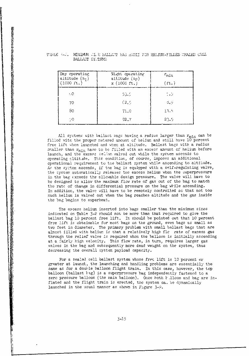
M3)E 4MIN24AU -I-E 1-ALLA.2T bTdRAD i FOR ,1i~AY1'-? I1ED ZFALIAD CEl-LBALLAiT SY -l'-"
Day operating Night operating ri
altitude (h1 ) altitude (ht2)( ooo ft.) x (looc ft.) (ft.)
70 (2.58071.0 15
".'0 t2.7 23.5
All systems with ballast bags having a radius larger than rmin can befilled witn the proper metered amount of helium and still have 10 percentfree lift when launched and wihen at altitude. Ballast bags with a radius
smaller than rmi. have to be filled with an excess amount of helium before!auwnch, and the excesc :ee'un valved out while the system ascends tooperating Jtitade. This condition, of course, Lmposes an additionalonerational reauirement to tne ballast: system while ascending to altitude.As the system ascends, if tne bag is equipped with a self-regulating valve,the system autoratically releases toe excess helium when the superpressurein the bag Exceeds the a!lo'rble design pressure. The valve will have tobe designed to allow the maximtum flow rate of gas out of the bag to matchthe rate of change in differential pressure on the bag w'ile ascending.
In addition, the valve will have to be remotely controlled so that not toomuch helium is valved out when the bag reaches altitude and the gas insidethe bag begins to superheat.
The eycess heliunm inserted into bags smaller than the minimum sizesindicated on Table 3-2 should not be more than that recquired to give theballast bag 10 percent free lift. It should be pointed out that 10 percentfre lif .. obtainable for most bags on the ground, even bags as small astwo feet in dia_.eter. The primary problem with small ballast bags that arealmost filled with helitum is that a relatively high flc rate of excess gasthrough the relief valve is required when the balloon is initially ascendingat a fairly high velocity. This flow rate, in turn, requires larger gasvalves in the bag and subsequently more dead weight on the system, thusdecreasing the overall system, payload capacity.
For a sealed cell ballast system whose fret. lift is 10 percent orgreater at launch, the launching and handling problems are essentially thesame as for a double balloon flight train. in this case, however, the topballoon (ballast *hg) is a superpressure bag independently fastened to a
zero pressure balloon (the ..main balloon). Once both b .!Ioon and bag are in-flated and the flight train is erected, the system ca.. be dynamicallylaunched in the usual manner as shown in F:gre 3-.
3-2.5

Helium Filled
Wind A Main Balloon
Inflation
// Parachutes
Payload
Figare 3-9. Launch Configuration for Ballast Bag Filled with Helim,
Now consider the load stresses exerted on the bag fabric -when the bag
has the greatest amount of free lift. For example, consider a 2-rail, 25-foot radius ba6 whose daytime operating altitude is 80,000 feet. At night,when the syst~n drops to a lower altitude (75,600 feet), the bag super-pressure decreases e-nd its net lift increases. From Report No. 1 it wasfound that:
G, (Night gross lift) = 192.7 lb."J2
w Bag weight)-1501 in l.
Fb2 = 77.7 lb. (niet lift of 25-footradius bag at 75,6003feet)
3-16

Following the exmplc given in Section IIIB with the saxne J10* load:iijlt', the linear stress, Oioad, on the bag fabric is now equal to 0.56l)./ft., or a reduction of less than 0.3 percent of the allowable linear't'roe: due to differential pressure (S-p) or of air ballast capability.
In addition, when the system rises to its operating altitude during the
day, the net lift of the bag decreases, thereby reducing the load stressoni the bag fabric to a still smaller figure. Therefore it is concludedtihat the flight configuration shown in Figure 3-8 has little effect onthe ballasting capability on the system.
Inflation Techniques. The primary problem for the flight configurationjust described is the method used for inflating both balloons and erectingthe flight train. One method for inflating both balloons is shown onFigure 3-10. A regular laimch roller arm can be used for holding down the
main balloon during its inflation. The inflation of superpressure balloons,
however, rresents a slightly different problem if the bag material is Mylar.Since pure Mylar film is more slippery than polyethelene or scrim balloonmaterial, it is necessary to use a "Clutch Launcher" that can firmly .aold
the material in place without the material slipping and minimize the
Ballast Bag Bubble(7' - hO' Diameter)
Wind
Clutch Launcher ( K
varachutes Main Balloon ) / Inflation
Roller Arm Bag Suspension Duct
Launcher Tapes G~roundCloth
Figure 3-10. Initial Inflation Phase (Ballast BagFilled with Helium)
3-17

stresses on the fabric. The "Clutch Launcher" (Figure 3-11) has beenused successfully by the Air Force for numerous superpressure balloonlaunches and appears to be an ideal launcher for inflating Mylar bal-last bags with helium.
IN
Figure 3-11. AFCRL Clutch Launcher HoldingDown a Superpressure Balloon
Basically, the clutch launcher consists of two light, foam-paddedclutch blocks which pinch a loop of balloon fabric. The balloon isfolded so that all seals occur at the outer edges of the folded sy.emand the clamping blocks are located at these seals. Inside the loopof balloon material is a padded lightweight roller which prevents theloop of balloon fabric from slippinG through the clutch blocks. Whenthe superpressure ballcon is filled with the ri3ht amount of helium,the clutch blocks, which are held down by a ground line, are releasedallowing the clutch blocks to fly alart and the roller to fly o4t. Abungee line connected to the roller prevents the roller from flyingout too far and striking personnel around the balloon and also allowsthe roller to swing clear of the b-lloon ar It rises.
3-16
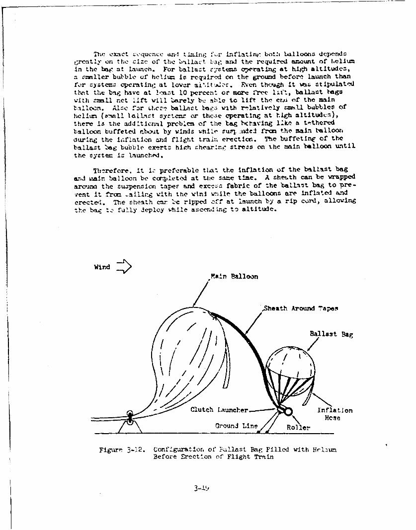
tCrvatly or. the cizc' of the "1 £azt 11ae and the required am~ount or iie).iumIn the beW. at launch. For ballazt ryt oprating at high altitudes,Smiller bul'ble cf hceu= 1v rcq'iir'_d on thir fjround before laiunch than
for z~yrtcmz cpcrtin; tit lover ait,.mt. ,n thcj~b It WIZ; stipulfttedt~t h bmg ?vivo at !(cnt 10 pcrcent or mre Vrvv lit baU~ast bag*
vitJI =mall ne~t. I I. will olatre baý_ Ole to li" t-hm Crl f h maintllocn. f.r OxC:i bali~t bagz; with r,1.±nbrely &mhU bubbles ofh~1ii~.(znll loaiiqct sy~rte~r hc e pratt~ni :%t rhleh altitudvi),
there Is "he add Itczml prcb.cm of thm ba~g bC~avin&j 1;.ke a totthervdtsalbxxm buffeted nl"oat by wImds utille souvl -kdeJ :-- the main t'ft~lollduring the isUXlatio~n and fligh~t. tmrin erection.. The 'bu1Tetine of theb4!lli3t. l'wag bublble cx'ertzz hIgzh chear:r1 stress or. the mainl balloon w'&tii.the ,r-t= I-- L'aunched.
Threfore. It 1: preferable that tte inlation of the batllast bagand mair. balloon be completed at ti.-e sanme t±.ae. A seheu.th can 'be wrappedarauna the suipen-sio t-aper and exc-ý, fabric of the ballast beigj to 'ore-w'ent It, fr~r _aitir~ with th-e ivini wt~ile thm b~iiloon are inflat#ed widCrectewl. The sheath m~r "ýŽe r1ppred c~f at launch by a rip cordj allowingthe ba, to fl~aly deploy while acendl.nf VD altitudte.
Wind4>fi tla
,Sheath Around 'rapes
Figure 3-2. Conf 1guratiozn of PFallast Bag, Fillod with 11lctiumBefore Erection of Flight Train

11i0 thc baillo:t bLig ind tht: m•in balloon are inflated at the sametJo, the ballast bag should be held as close as possible to the mainballoon wlile the top fittint of the balloon begins to rise. If the sus-pension tapes and excess bag fabric are long enough, th,, inflation -anbe accomplish-ed as depicted in Figure 3-12. Otherwise the ballast bagshould first be fully inflated and slowly be picked up by a boom craneand sw•ng into position -while the main balloon is inflated and begins toerect as shown in Figure 3-13. The primary difference between the in-flation phase configurations shown in Figures 3-12 and 3-13, is that thelength of the suspencion tapes and excess bag fabric is not long enoughto permit the main balloon to be fully inflated and its top fittingerected while the clutch la-ncher for the ballast bag is held down tothe ground. The inflation procedure. shown in Figure 3-13 is definitelymore ccmtplex and hazardous to personnel and the main balloon especiallywhen the clutch launcher is released.
Sheath Around Ballast BagSuspension Tapes
Main Balloon Bo rn
Q .//Clutch
/ j) Launcher
RollerALauncher
-' Inflation Duct
F 'igure 13. Inflation Confige.tioc of Ballast Bag Filled -withHelim with Snort Sisp.enzion Tapes
Before conisidering this second inflation method a check should bemade to determine the extra dead weight rejuired for lengthening thesuspension tapes or adding an extra cable length between the top fitting
3-5 )

of the main balloon and the support ring where the bag suspension tapesarc tied together. If this extra weight does not diminish the systempayload capacity below the minimum requirements, it is preferable thatthe clutch launcher be anchored to the ground and the support tapes andcables betweeni the two balloons be lengthened.
Handling and Launch Techniques. Once the main balloon and ballast bagare inflated with the correct amount of helium the erection phase maybegin. The clutch launcher is first released allowing the ballast bagto swing up over the top of the main balloon. When the bag is almostover the main balloon, the roller arm launcher can release the mainballoon. Both the ballast bag and main balloon can rise together, thuserecting the flight system to the launch configuration as shown inFigure 3-9.
If the ballast bag has a very high net lift and Can actually liftthe top of the main balloon, it may be possible to fill the ballast bagfirst while filling the main balloon and release the ballast bat fromthe clutch launcher before the main balloon has a large enough bubbleto lift, its own top fitting. (Figure 3-14). In this manner the ballast
WindfQ
SuspensionTapes
Main Balloon Inflation
Duct Tied
Inflation Duct - Off
Parachutes- /Ground
Cloth
Figure 3-14. Inflation Configurati. r' of High Lift Ballast Bag
3-21

a~,- iL3 aýl~owed to hold thIc main balloon bubble up while the iJf±Lationi.- -,)%iqted on the main balloon. When the main balloon is fully in-fated. the roller arm releases the main balloon and the system thenerects itself to the launch config-uation. Notice, however, that thisinflation procedure is definitely wind limited and should be used onlywhen the ballast bag requires enough helium at launch to give it ahigh net lift and the bubble of helium in the bag is suspended fairlyclose to the top fitting of the main balloon. In all cases thus fardescribed it is important that the ballast bag have a reasonably tightoubble so that maximum. control is possible until the system is erectedand launched.
Other Flight Configurations. Let us now consider other possible flightconfiglirations for sealed cell systems where the ballast bag has lessthan 10 percent lift or even a positive weight. Though theoreticallythere are no launching restrictions in relating to the size of thehelium filled bag on top of the main balloon, it may not be desirableto insert excess helium into the ballast bag and valve it out whilethe system ascends. If the helium-filled bag were located elsewhere inthe balloon systemthen the primary problems are control of the heliumbubble and the orientation (up and down) of the ballast bag, especiallywhen it has lilt at night operating altitude and weight when fully pres-surized at day operating altitude. One possible flight configuration isshown in Figure 3-15 where the bag has a double set of suspension tapes;
Vain Balloon Exhaust Duct
Instrument ParachutesPackage
Ballast Pag (FullyPressurized witij. 4 ' Sspesin Tpe
(Ballastio Tapesrs
Orientation Weight T[--ruzn-nts)(Ballast Hloppers, instruments*'-
'igure 3-15. Hei-Filled Sealed Cell Ballast System-ung Under Payload

onk' 'Ot of' tapes suspends an "orientation" weight onto the bag itself sothat the bag is always hold down even whcn it has free lift; and the other-et of tapes suspends the bag and the orientation weight underneath thepayload bar.
The orientation weight, which can range from 5 to 40 pounds, makes uppart of the total payload carried by the balloon system. The orientationweighi should be slightly heavier than the maximum lift of the ballast bagif the bag has any positive lift. Otherwise, the orientation weightshould ve heavy enough to hold the excess fabric of the ballast bag in adownward direction to prevent the bubble of helium in the bag from shiftingabout and causing the lower end of the bag from floating upward. In eithercase, it is important that the orientation weight be as light as possiblewhile performing its function so that the linear load stresses on the bagcan be kept as low as possible. Depending on the size of the orientationweight required, it can consist of parts of the instrumentation necessaryto monitor the condition of the bag (temperature and pressure), and ifhigher orientation weights arp required (20 or more pounds), the compen-sation ballast hopper can also be supported at this point. The purposeof the compensation ballast is to compensate for lift loss either in themain balloon or ballast system due to helium leaks. Actually, it wouldbe favorable to locate the compensation ballast hopper underneath theballast bag so that the ballast can fall free of the balloon system. Ifthe ballast hopper were suspended over the ballast bag there is a pos-sibility that the solid ballast would collect on the ballast bag or evendamage it.
Basically this type of system is similar to the air-filled sealedcell systems as shown in Figure 3-2 with the exception of the orientationweight slung underneath the ballast bag. An inflation proceduresuch asdescribed in Section IIIB for the air-filled system, may be used. Thelightweight net can hold the bag in a tight bubble while the bubble is in-flated and can prevent the helium lift from floating portions of the bagmaterial around the instrument payload suspended from the boom crane.Care will have to be taken to prevent the double sets of suspension tapesto the ballast bag and the orientation weight from being tangled with theexcess bag material when the inflation net is removed. This can be ac-complished by taking extra precautions in folding any excess bag materialand tapes inside the netting and assuring that the bubble can expandfreely while the ballast bag is being filled.
The erection and launching procedure for the flight configurationshown in Figure 3-15, can be the same as that described in Section IIIBfor small bubbles (7 to 20 feet in diameter). For large bubbles of heliumwith low lift, the inflation, erection, and launching problems become moreacute for this type of flight configuration.
Another flight configuration possibility for low net-lift helium-filled ballast bags is the suspension of the bag imnediately above the in-strument payload iith a load line running through it as shown in Figure 3-7.As explained for air-filled ballast systems, this configuration presents
3-23

unuouai ana complicated fabrication and launching problems for larger
Another possibility is to join the ballast bag to the main balloonin tandem fashion as is shown in Figure 3-16. Instead of venting theexcess helium from the ballast bag to the atmosphere, the helium is al-lowed to flow through a transfer duct into the main balloon. In thisconf1*;ration the ballast bag is completely filled and the main balloonremains empty while on the ground. The center fitting between the twooalloons contains a relief valve for controlling the transfer of heliumand provides a point to which a mainstay cable can be connected forerecting the flight train and allowing the balloon system to be staticallylaunched. Basically this configuration is a tandem balloon system w'ith asuperpressure controllable launch balloon on top.
Thansfer Duct Helium FilledBallast Bag
CenterFitting withR e l i e f V a l v e S s n i
SSuspension
Main Balloon Tapes
Parachutes
Mainstay
Payload
Figure 3-16. Tandem Balloon Configuration for SuperpressureBallast Bag on Top of Zero Pressure 3alloon
Baliast bags 16 feet or more in diameter can hold enough heliumwithout becoming superpressured while on the ground to fill the largestmain balloon it can ballast as well as to superpressure the ballast bag
3-24

it,,1f to the propm.r op,.ritirg pressurc_ at operatic-r altitude- of 60,000f'eet or more.
Two distinct advantages are apparent for the tandem balloon configu-ration. The first is that ILss helium 1,i -asted since the excess hŽl.Lumfrom the ballast bag is vented into the main balloon instead of into theatmosphere. Second, the tandem balloon configuration lends itselfreadily to static launch techniques whic have been used many times forlarge tandem balloon systems. Experience has show in the past thatstatic launches for large tandem balloon systems are less wind sensitivethan dynamic laun2hes.
The launching and handling techniques for the tandem balloon configu-1! ration of The heiium-filled seaieý r -s111 'ezr2: lar to thosetechniques practiced for systems sucn as Stratoscope II, and ProjectVoyager. A development prograr., however, has to be conducted on the de-sign and fabrication of a center fitting with a controllable transferrelief valve and techniques for joining a s'iperpressure balloon to azero pressure balloon with transfer ducts and a center fitting betweenthem.
D. P0W•ED1 BAIL fT SYcSTifc
Since Report No. 1 concluded that powered systems are not particu-larly practical using state-of-the-art components, it is difficul at
this time to be precisc about the flight configurations, launchingproblems and handling techniques for powered systems. It is uot knownwhat type of winches, compressors, or power systems will be eventuallydeveloped for these systems; therefore, configurations and techniquesthat may be used are somewhat speculative. If studies are pursued inthis area, it will be necessary to reevaluate the general configurationand techniques described and to determine where changes, if necessary,must be made to rake tne systems and their associated flight configura-tions compatible to the newly developed components.
Let us first look at the flight configuration of a mass expulsionballast systemn with a compressor as shown in Figure 3-17. The only basicdifference between this system and the non-powered mass expulsion ballastsystem is the additional payload carri J on the load bar for the air com-pressor and the electrical power system. Provided the compressor andpower systems are reasonably small in size, the same inflation, erectionand launching techniques used for air-filled ballast systemis can also beused for air-filled towered lallast systems.
e 3-2r5

iii °
Main Ral.oon IExhaust Duct
Parachutes Power System(Solar Cell OrientationBatteries, Power Con-
Instrument Control / ditior.ing, Solar Cells)
Package Compressor
Load Sutspension Tapes
Air Ballast Valve
Figure 3-17. Flight Configuration of a PoweredMass Expulsion Ballast System
The winch powered sealed cell ballast system filled with air shouldbe similar to the flight configuration as shown in Figure 3-2 wi-eh theexception cf a winph on the payload bar and a ca'Le running dc.wn to theload suspension tapes of the ballast bag. The cable running from thewinch to the ballast bag should be fully reeled in when the system is!aunLhed. Again, as for the mass expulsion ballast system with a can-pressor, the inflation, erection, and launching techniques should alsobe similar, provided that the winch and power systems are reasonable insize. For large rowered air filled ballast systems, the same inherentlaunching and handling problems exist as for large non-powered air ballastsystems.
The helium filled sealed cell ballast system on a powered winch how-ever has a few more complications then the non-powered sealed cell system.filled with helium. In order to keep the :jow=r requirements on the winchto a minimum, it was found in Report No. 1 that the net lift of the en-tire ballast system should be virtually nil vhen the winch is reeled outand that the only increase in lift should be attributed to the "Air"ballast of the system when reeled in. This approach, depending on the netlift of the oallast bag, requires that part of ,he payload sxch as thewinch and system controls be suspended underneath the ballast bag as shownin Figure 3-18. This configuration lOobis a linear stress on the ballastbag approximately proportional to the ne. lift of the ballast bag itself.
3q-26
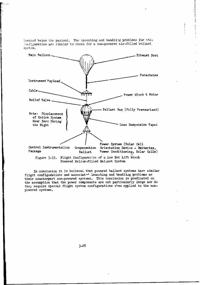
located below the payload. The launching ard handliig problems for thsz
',lejuration are similar to those for a non-powered air-filled E'dlast
Main qalloon. Enhaust Duct
Instrument. Payload Parachutes
Cabl.e-.Power Winch A Motor
Relief Valve
Ballast Bag (Fully Pressurized)Ncte: Displacement
of Entire SystemNear Zero Durnthe Night• Loaa Suspension Tapez
Power System (Solar CellControl Instrumentation Ckopensation Orientation Device - Bktteries,Package Ballast Power Conditioning, Solar Cells)
Figare 3-19. Flight Configurat'crn of a Low Net Lift WinchPowered Helium-Filled Baliast System
In conclusion it is believed that powered ballast systems have similarflight configurations and associat- launching and handliig problems astheir counterpart non-powered systems. This conclusion is predicated onthe assumption that the power components are not particularly large nor dothey require special flight system configurations w'ie applied to the non-powered systems.
3-28

'3ect onl IVI
CONCLUSIONiS
In this report some of the more pract~cal aspects in the applicationof air ballast systems to the control of free flight balloons hate beenexamined. Also exar±Lned were instninenta-tioia and controls associatedwith epach tvpp of' ballast s-ystemm. 7-or non-powered air be].last systemas(mnass ex-)ulsien and sealed cell types1) it appears that off-the-shelftransducers -,or prcssure P-nd tempe±rature can meet thE: requiremenets forall sizes of brallast systems. The st-andard A/TD conversion units, VCO'sand other similar analog con'~ersion techniques can also be obtained,Pitter through design or use of off-the-shelif components, fo'r ter,_Met~eringthe reGi~red data to ground control stations using standard balloon telem-etry eq;-ipment. Allthovgh higher accuracies and resolutions are requiredfor large ballsst systems, especially for differential pressure and alti-tui~e i::-easurement~s, the overall cobts, for instru-mentation are ap~rroximaltelythe same for all sizeF of ballaFrt systemis.
The required ballast control valves for air ballast systems, however,are not readily obtainable and tnose that are artailable generally requiresome modification for adaptat~ionm; to the specific reqtir ments of a par-ticular ballast system. For examplle, simpli mechanical spring typtn reliefvalves for small (25 foot diameter or smaller) balliast bags ar- suitableif modified to allow remote electrical actuation f'or more accurn~e control
4C the intcrnal pressure of '-he bag. M-chanical spring type relief valvesare a ýýIlar, with setting accuracies about ±0 percent. Large '.a Llast
Mk bags, however., require more accurate pressure settings at very low differ-ential pressures and this accuracy cannot be maintained by simsple sprin~-kaccion relief valve5. Specially desi&-ed EV-13 type >.,,_liuLi valves will1,ave to be designed along with appropriate circuitry anld low piressuredifferential t1ransducers focr aut-omatically cor.trolling pressures with~i alarge sealed ce.il ballast bag.
Instument-ton and controls for powereft air ballast systems at this
ti"e cannot be discussed in detail because the major components, such asligrhat-weight. low powered winches ana comressors, are not available.When de- elopment work in this area specificnally aimed at the requirementsfor powered air ballast systems is accculished, instrumentation and con-'' trols for powered systems should be available utilizing off-the-shelf
,!he~ flight conf igura'tion off ai. air ballast system is dependent onboth the gas ufsed inside the ballast bag and the size of the buag. Thelaunching and handling problems associated w~ith the flight configurationof an air oallast system depends not only on the size of the bag but alsoon the operating altitude of the system. The higher the altitude at whichthe sys-tem qperateýs the greter the gas expansion. Consequently, for a

given size bag, a smaller amount of gas is rcquired at ground level forhigh altitude flights.
In determining the flight configuration of an air ballast system,
it is necessary to cont,*ider tho handling and launching problems associatedwith the system. For air-filled ballast bag systems it was fcund thatballast bags 50 feet in diameter or larg:er ver'. to'x difficult to handleor launch with conventional equirment ani teciwiques. It is concludedtherefore that new launch equipment and tEch~iques, along with new ha.d- Iling techniques, must be developed in order to launch and fly large air'-
filed bea.Last systems.
ReiiLmn-fil3 A ballast systems, however, lend themselves generall-, toconventional har.dling and launch techniques, especially for large ballastbags. Still, there are some problems associated with helium-f.lled ballastbags that have less than 10 percent net lift at launch. If tL.e bag isover-filled with helium to achieve more than 10 percent free l.ft at launch,the excess gas must be vented off as the system ascends to operationala!titude. While this is not considererc a critical problem, it is necessaryto ensure that the relief valve is properly design-ud to vent out tne excesshnlium at the proper rate. There are flight configurations for helium-filled ballast bags with less thian 10 percent free lift which can behandled with conventional equipment and techniques. However, for some ofthese co. figurations, new balloon fabrication techniques must be developedbefore these flight configurations can be used.
In conclusion, air ballast systems can be instr=ented and flown inmost cases with conventic.rl or off-t'le-shelf components and equipment.Systems using large jayloads are mort difficult to handle and launch thansmall payload systeras. There do not appear, however, to be any design].±mitaions in the size of the ballast system as far as handling, launching,,- instrumentation other than limitations imposed by th- 2abric parametersor 'the ballast bag, as discussed in detail in Report No. 1. In addition,balloon flight systems with helium-filled ballast bags can not only carrymuch grenter payloads than air-filled bag systems, but, especially for largeballast systems, are also easier to handle and launch.
4-2

fI
| i
APPKENDIX A
DZEMNJ•ATICN OF WIIAUSTIPG TIME FOR PPESSURIZM)SP}i-ThF WITH CIRCULAR ORIFICES
A spherical balloon is fiil ýd with air or helium under press-.zie Pl.When the ballast valve with a c -ular orifice of area Ac is opened, thedifferential pressure, A P, drops as the gas inside the bag is exhau5tedthrough the valve. The problem is to determine the time it takes, oncethe valve is opened, for AP to drop to zero. Using Figure A-1, thefollowing ass-mptions are nmde:
1. Stretch of the bag is negligible.
2. No heat transfer occurs during exhaust stage; that is, we haveadiabatic expansion of gases:
k-1
Adiabatic excpansion: T- (P2 -k (A-k )
ada3t Flow of the gas through the valve is described by compressiblejadiabatic flow (w) through a circular orifice:
1f~ck-l k- 1• w c4PC. CA,• -- (A-2°)Pk• 21 P2
where,
C = orifice coefficient (0.61)
R = gas -on~tant (air 53.5, nelium 1.66)
gc = gravity constant (32.2 ft..,sec.)'
w = flow rate (lb./sec.)
I A-31
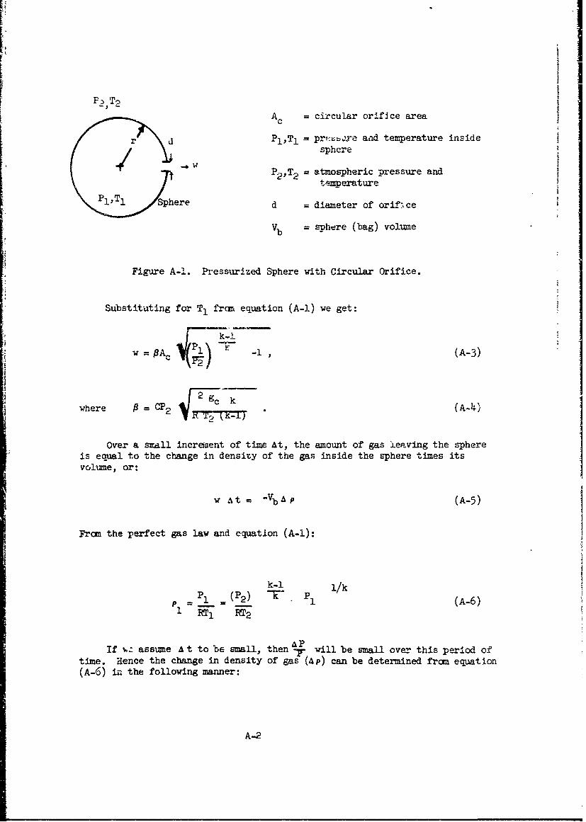
A, circular orifice area
r dPl,Tl r,•• and temperature insidersphere
-P2,T2= atmospheric pressure and
temperature
Sphere d = diameter of orift•ce
Vb sphere (bag) volume
Figure A-1. Pressurized Sphere with Circular Orifice.
Substituting for T, frcin equation (A-.) we get:
w A P-, (A-3)2gc
where P=CP2 . (A-4)
Over a small increnent of time At, the amount of gas leaving the sphereis equal to the change in density of the gas inside the -sphere times itsvolume, or:
W At = -VbA P (A-5)
From the perfect gas law and equation (A-1):
k-i i/k
1P I (P 2 ) 1 1/ (A-6)
APIf i assume A t to be small, then T will be small over this period of
time. Hence the change in density of gas (Ap) can be determined from equation(A-6) in the following manner:
A-2

k-I I/k 11/k
RT2
k -1 11/k I/k
K L01 - (i AP)
k-i 1/k
t;RT 2 . 2 (A-7
(P)K P (A-8)
Substituting eq~uations (A-3) and 'A-8) into equation (A-5) produces theI following differential equation:
k-i
Vb( 2 P
(A-9)
k-i
Rk2 c k IP)T -
I I' we integrate both bides uf equationi (A-9) from time t 0 to t = t(exhaut iplee), we can determ~ine the total exhaust time tc ytefolwn
I equation:
-~~ b dP(A )
V2 (A-11
The integral in equation (A-la) may be integrated directly by the fol-lowi-ng 5ubstitut-ion:
'A-

Ik-i
[~ =ec~ (A-li)
Then by differentiating both sides of equation (A-1l):
2k2k P?2 TC (A-12)
dP _2 [see t- d
Substitution of equations (A-11) and (A-12) into (A-IO) yields
Vb 2tr 2-11 (A-13)Ac C ge k (k-l) RT2(ec•) d
C2 J
k-1
where .1,2 = arcsec p 1,2
P2
If thp bag is filled with air, k = v= 1.4; thus
f 2tc -- di (A-14)
Ac C "28gc RI2 f cos
Let v air = .__ ; thus (A-15)
C V.28 g, r A2
A-4

Ii2tc --- . r_ .( -
t - a .L [ sirn + 3 ( sine + Ln~sec 4- +tan $ )Ac L cos4 cos 4 8i
1-k
Let x = 2o (p ) k (fron Equation (A-li));
then as a final result for an air filled bag:
Y-2
=_ air r xV + 3 v"' x+3 in-+- x-n9 (A-16)
c 7 x -x X
where xlc2 =(PP ) .286
Similarly, for a helium filled bag, where kiHe = 1.66
,x2
t H"e ( VTW + 1 in 1 + T xr J (A-17)c AC 2x 2 L VX J XI
), 398
where x!, 2 = 3 =C %4 .55 9c RT2
For a specific example, assume a 100 foot diameter 2 Mil Mylar ballastbag at 80,000 feet altitude pressurized with air to S 1 = 10,000 psi. Theproblem is to determine what orifice area (Ac) is required to exhaust thebag within 30 minutes. The initial internal pressure P1 of the ballast bag
is determined by
P 1 = P2 + AP, where
24 S1 tb (A-18)AP=
r(I + 3S,/E)
A-5
'Im mn l lmli1, l m mil II il I m ipil n

Simmary of conditions at 80,000 feet altitude:
P3 = 5#,/ft: r = 50 feet
T3 = 3980 R tc = 30 minutes k1800 seconds)
Rair = 53.5 0/ft S1 = 10iOO psi
"kair = 1.4 t = .002"
C = 0.61 E = 800,000 psi
gc = 32.2 ft./sec2
iC
From equation (A-18),
P1 = 58.0 + 9.27 = 67.25 #/ft 2
From equation (A-15)
• ~4 , 503" - lO
air = 3 = 1.945 x 10-
.61 q .28 • 32.2 •53.5 "398
From equation (A-16) then;
180C) 1.94,5x10 3 [ -1-x + 3 -/ -- --x 3 in _ _+ -V_ -_x_ 9584_.
or
Ac = .228 ftV2
A d .228 ft2
c T.
oro
d = 0.54 ft = 6.50 inches
Thus we find that a 100 foot bag should have a 6-2 inch diameter valve inorder that all of its air pressure be -valved out within 30 minutes. If we
A-6

0. &ily require percent of the pressure to be valved out in 30 Tinates,then
froi'i equation (A-!5), we find tha. a valve 5.3 inches in diameter will be.-ufficient. At 80,000 feet altitude, a 100 foot diameter bag can con-tain 105 pound,, of air ballast. Thus if we use a 5.3 incn valve, approxi-!!Lately 6.6 pounds of air ballact will be left after 30 minutes. It istherefore concluded that a 6 inch valve should be sufficient forexhausting a 100 foot diameter air pressurized bag at 80,000 feetwithin the time of sunset effect.
If the bag were filled with helium, equation (A-17) is then used:
K = 386 0/ftHe
C = 0.6! (assumed)
k = 1.66 P
2thus YHe = 5.19 x 10.
Using equation (A-17):
1800 = .9x0 [VTi~ 1 in 1+ .4
Ac 2x 2 /]
A 0 710f 2 d = 3.61"c .
Thus, if the 100 foot diameter bag were pressurized with helium in-
stead of air, a 3.61 inch diameter valve could fully exhaust the bagwithin the required 30 ninutes.
I
A-7

AXPENDID B
DETEMMIATION OF EXIAUST 1REUIRWMTS FOR AN ASCENDinG SEALED CELL SYSTV24
A:-,ize a bag containing a certain quantity of gas ascends to sanealtitude ho aL which point the bag has a differential pressure A P0. Therelief valve is assumed to fully open when the differential pressurereaches AP, and remains open until the balloon reaches altitude. Inactual practice, the valve should shut whenever the differential pressuredrops below the deired final differential pressure A Pf. For simplifi-cation, however, we ma'-o the former asstz-aption in order to assure ourselvesthat the valve has suff-cient capacity to valve off enough excess gas with-out exceeding the maximum allowable differential pressure in the ballast
, bag. If the valve is large enoughi, the valve will shut periodi :allyallowing the pressure to build back up in the bag while ascending, and openwhenever the differential pressure exceeds APO.
From equations (A-2) and (A-5) in Appendix A;
k-!dFl/ (pl/p2) k CdP=/ (- .P 2ICAc 2 k RbT2 dt (B-l)jF29 k_-7 k-B-1
P2 [11
At this point, a basic assumption is made that the atmosphere over theregion of interest is isothermal and that the ratio between the pressure inthe ballast bag and outside ambient pressure remains 1constant while thevalve is open and the bag is ascending i.e.,
P1 P2' (B-2)
where P2=, ( 0 1 ) = Po (initial opening differential pressure)
a. - ao = constant.
Equation (B-1) therefore can be rewritten as:
dP 1 - A dt, where (B-3)
B-1

ii
rCA 2 kR T2]2onstant -[ lk
The differential equation (B-3) is solved by inteLrating both sidesof the equation
- AtP, P e (B-4)"1 = 0
Note at time t = 0, P, = a0 .? 2 where P2t 0 is the ambient
pressure when the valve first opens.
For further simplification, it is assumed that the ambient pressurefollows the basic hydrostatic law:
P = P2 e -5)t=2 C
Frcm equation (B-4), A = constant; assume g* = gc (constant gravity).
Then from equation (B-5)C
v = dz/dt = ARaT2 = constant (B-6)
That is to say, if it is assumed that a,= constant, then the asce-ftvelocity v must albo be a constant. It is therefore found that giv.n aninitial opening pressure a Po and an ascent velocity ' , the required orificesize of the relief can be determined:
1/kA Vb 1 o , (B-7)
R RaC ;l2kg RbT 23 [T2k -1
Ik -(k-l)
where APO
= ± + P2 t
B-2

Note tnat I i - the ga2 constant for awbient air and Rb is the gascontart for tne gaz inride the bag. If the bag is filled with air,Ro = Ra.
As an (:°-mple, consider a 16 foot diameter 2 mil Mylar bag filledwith helium which is lautnched with 20 percent free lift. The first stepin the problem is to determine at what altitude the bag becones fullypressurizeC. It is assumed that the bag can withstand a skin stress '.pto 12,000 psi and that the relief valve is designed to fu2ly open at tht•setting.
From equation (A-18) ir1 AYpendix A, this skin stress i,, equivalentto a bag differential pressure of
a = 24 • 1 21000 .)02 f2a P 000Tý = 68.6 #/ft
0 b (1 + 3 12,000/500,O00)
The gross weight zf the bag is given as:
" 2 824 ir W. 4 • 3.14 8 (0.0147) = 11.8#
With 20 percent free lift, the gross lift of the gas inside the bagmust be:
Gb2 = (1.20) (11.8) = 15.6#
The specific lift of helium oB the ground is given a.s 6.58' x 10-2 t./ft 3
and the density as 1.06 x ]0 ib./ftK.o Therefore Lhe mass of heliuum in-S~side the bag is:
15.6 lb. × (1.06 x 1O-2) 2 5.52 lb.
6.587 x !0-2
From the perfect gas law, P __ , we can find the mass of helium in-
side the bag when fully pressurized:
2.52 = Vb P! 3 RL r 3T+
5.8 (P2 + 68.6)2.52 ______
T2
B-3
I

I
'Ititude h- which Jaia a correjponding air temperature T2 and pressureP that will satisfy the conditions of the above equation is now determined.
NOTE: Assume Tp = T, initially.
By iteration, we lind th•at at h. = 68,500 feet. the bag becomes fullypressurized and begins venting helium. From analysis of balloon flighttrajectories velocities of 1,000 to 1,200 fect per minute are not unlikelyat this altitude if the operational altitude of the balloon system is Tboe68,500 feet.
At 68,500, P2 = 101.4 p/ft . The required area of the releft = 0
valve orifice is therefore determined from equation (B-7):
0 = 1+ 68.6 = 1.675
= = 53.5 0/ft.
Rb = 3 0/ft.
k = 1.66
= 1200 ft./min. = 20 ft./sec. (assume)
T2 = 391 *R
Ac = 1.95 x l0"3 ft 2 = .281 in2
d' = Ac .281 in 2
d = .39 in.
Therefore a relief valve with an orifice diameter of .596 inch willbe able to valve off the excess gas on a 16 foot bag at 68,500 feet ascendingat the rate of 1200 feet/minute.
If the operational altitude of the ballast bag is 70,000 feet, thearmbient pressure then is:
P 2 = 94 #f
Since w was determined to be 1.675, then from equation (B-2)
2APf=P ( 2 1)=63.5#/ft
This corresponds to a skin stress on the bag of about S1 11,000 psi.
Since th. operational pressure should be about S1 = 1.0,000 psi, then thevalve must still remain open for a short time longer in order to bleed theextra pressure in the bag to the right level.
B-h

APPIIDC C
DETN1INATION OF LARGEST BUBBLE ThkT CAN BE HANDLED BY A 40-FOOT BOOM CRANE
Assume that the ballast bz-g forms a spherical bubble of a radius rwhich is suspended a distance x from the top of the boom crane of lengthL. Assume also that the crane is well padded and that the maximum sizebubble rests tangent to the boom and tangent to the level of the base ofthe boom as shown in figure C-2
x
Figure C-i. Determination of Maximum Size Bubble With 40-foot Boom Crane.
"If the base of the boom is about L feet above the ground then the bubb] e is
kept high enough off the ground that it will not scrape the ground ý--ii.e theIcrane moves around during a dynamic launch.,
From the geometry of the above figure the followir.g equations are written: -
L sin = x + 2r (C-!)
x = r/cos 4-r (C-2)
C-1
L!
I

Simuitaneous solution or" equations (C-i) and (C-2) yields the followingfor r:
r= L sine0 (C-3';(sec 0 +1)
To find the maximum value for r for given boom length L, we differentiater with respect to 0 and set it equal to zero:
2dr L + L cos€ - L tan2€ 0 (c -4)
do (sec +)
Equation (C-4) reduces to
2cos '4 , cosO -1=0 (C-5)
Solving for cos 0 by the quadratic formula,
cos€ = -s ±v +4 . 0.6152
1r= 1
If the boom crane with an extension has a length 40 feet, then fromequation (C-3), the maximu-. bubble radius which can be handled is determinedto be:
(140) (0.669)
= +1 =10.2 feet
From equation (0-1), the distance the bubble is supported below the topof the crane is:
x = (40) (0.669) - 2 (10.2) = 6.4 feet.
C-2

If
Thc' results are iuxnimarized in figure C-2.
6.4' --
10.2Boom 40' long20.4, •
/ I ' 2 I I L0
Figure C-2. MaxiJiaum Bubble Size With 40-Foot Boom Crane.
IP-
C-3

A Air ballast; weight ofa.r In ballast bag less ibs.
weight, of' am'bient aa.r displaced.
AAea of ballast valve orifice ft 2
2E Modulus of elasticity lbs./in.
F Free lift lbs.
F(I) Function of fabric parameter dimensionless
Go Ballast bag gross lift lbs.
L Length ft.
N Percentage of superheat in main balloon decimal of ambient air
N. Daytime superheat effect: = mb decimal of TaI Ta
N2 Nighttime superheat effect: = mb decimal of Ta
P Pressure Ta lbs./ft 2
AP Differential pressure at time t = 0 iLbs./ft 2
0
APf Final differential pressure lbs./ft 2
Pressure in the ballast bag lbs./ft 2
R Gas constant ft./OR
R Gas constant for ambient air 53.5 ft./°Ra
Rb Gas constant for gas in ballast bag ft./°R
RHe Gas constant for helium 386 ft,'OR
OR Degrees Rankin
S Ballast bag fabric stress lbs./in2
T Temperature, general OR
Ta Ambient air temperature OR
Gloss -i

Symbol Definitio 0 Units
T-b Temperature of -as in bollazt bag6°
Tmb Temperature of gas in main balloon OR
Vb Volume of ballast bag, unstretched ft 3
Wb Total weight of ballast bag fabric lbs.
d Ballast valve orifice diameter in.
gc Gravity conztant 32.2 ft./sec2
g* Local acceleration of gravity ft./sec2
gL Specific lift of helium lbs./ft 3
h Altitude ft.
k Gas constant = Cp/CV dimensionless
n Percentage of superheat in ballast bag deci-al of ambientair temperature
r Radius of ballast bag ft.
s Ballast bag linear fabric stress lbs./ft.
S Ap Ballast bag linear fabric stress due todifferential pressure lbs./ft.
Sload Ballast bag linear fabric stress due toload forces lbs./ft.
Stotal SLp - Sload = s lbs./ft.
t Time seconds
tb Ballast bag fabric thickness inches
Lc Time to comrlete exhausting seconds
w Gas flow rate !bs./sec.
w Ballast bag unit fabric weight lbs, -"Pt2b
"Wmb Main balloon unit fabric weight lbs./ft2
z Variable altitude ft.
Gloss-2

I2virbo Definition Units
0 Pressure ratio; Pl/P2 dimensionless•0T
/3 Flow rate variable; C?2 v 2gc k lb/ft 2
T (k-1)
Flow time variable; Vb ft 2 -sec
A Differential symbol dimensionless
0 Load force angle on ballast bag degrees
Ob Superheat in ballast bag OF; b = n Ta
0mb Superheat in main balloon OF; 0 mb = a
7 Ascent velocity ft/sec
A Time pressure constant
SPi 3.14159
P Density of ambient air lbs./ft 3a
p Density of gas in ballast bag lbs./ft 3b
p Density of helium lbs./ft 3
He
Main balloon fabric parameter dimensionless
Subscripts
I Conditions during the day; or inside ballast bag
2 Conditions during the night; or outside baliast bag
a Ambient air
b Ballast bag
Gioss-3

Unclassified
DOCUMENT CONTROL DATA.- R & D 4(S*CWuyfl 0ii.ejIC49. Of utite. a, 04 i abstmel and tod...inr -~.let-ro S i... L.u. -,, it-1N. . lthe J-o, I. tI. -A 11,d)
bloilcu~rv~**u ICA TONLaboraoriesUnclassified
Silver Spring Laboratory .GRU114oo00 GeorgiaL Ave.. Silver, Smring.NM¶. 2(Y910
3 SEORT T4TSIg
FLIGHT CONTROL. SYSTEM AND 1AUJ~RNGG TECHNI(Z.M- FOR AIR
P SJci.ntifi. IN .66~n cetfcRprtN.F92-7C-12 Tcncl oe0070-a . T.OA (LCI ".8 652.02124 Sb 0.0-t tOLI# ,Nee)~ nS. . S e.D
6ý ONTATC RN O 632800 7C-19 OiMATc~,-7O679CPA NMCA
II. SUPROEC. TSK. AN D NI NO.T66 -0 -0 NScientifi ReportN. 2CIVT
app lcatingonsDe of aC-blls stemse foslet the cotogffene-flghtic
balon.s.htp o i ballast ejste, asdernd, ins Scihu entific7
Report No. 1, is analyzed for the cost, availability of materials,comnponents, and instrumentation required. In addition, for eachtype of air ballast system deemed feasible, the possible flightsystem configurations, associated launching problems, and methods tosolve the problems are investigated. It is the conclusion of thisreport that most air ballast systems can-, be instrumented and flownwith conventional or off-the-shelf components and equipment. Systemsusing very large payloads are more difficult to handle and launchthan smaller payload systems and prooably will require sanedevelopment in new launching techniques and~ associated equipment.
D D ',.14 73 Unclassified

20
UnclassifiedSecurity CiasueftfitI.
14. 96 "Nt LAN1 A .ISO 0 1L*N S
Air BallastBalloon InstrumentationBalloon Altitude ControlBalloon Launching Techniques
Unclassified6- f