for aeronautics - nasa · the wing characteristics calculated from general nonlinear section lift...
TRANSCRIPT

FOR AERONAUTICS
REPORT No. 865 _. :-
: I
METHODFORCA~$ULiiTING~$VI~~~CHAiACT~~iSTi& I I 1. " BY LIFTiNG-LINE +IiEilI$k tihNG'~&tiEAR, I 'SECTIONLIFT.DATA ,-
/ By JAMES C. SIVELLS and ROBERT ,H. NEELY
,
1947
https://ntrs.nasa.gov/search.jsp?R=19930091938 2018-09-19T05:44:55+00:00Z
-.
. W 0 na ; , ‘- I G
!z . .
L. .
,~ D
.’ DO
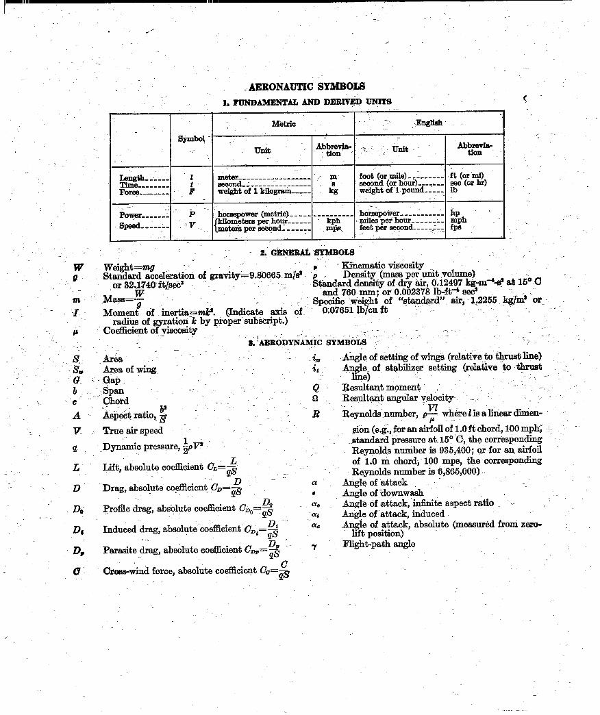
i~ao~~umc sm5oLs -, ~_ 1. FUNDAMENTAL AND Dl!W@D UNITS
‘. Meti Y-. ,jbgliak
- symbo! :..
_ unit / ._’ YEiT -
foot (or mile)-,: ______ .& (or mi) ----- ------;----- _ eeoond (or. hour)-,-y,, sea (or hr)
--Fore ___-____ weight of 1 kilogram-,,-- kg weight of l-pound----- lb ,’ - ~ -
-. sayer _____ ,, P -- homepower (met&)-- ___ __________ horsi$oyer __________ ‘- hp
w kilometer6 per hour------ . kph
’ __ .. -v .- {meterkper~ndl_,___ T- .mgks, ,mileeperhour ________ mph, _- ------- f-eetperyond _____ & fpa .-
c
r -
: ,, - 2. G@ElZA% ~SYMEOLS ),- -I.~ /
w&&t=& ..- _ *’ Standard acceleration of gravity~~9.36665.m~s~ -p’ 1
’ Kinematic vi&osity Density (mass per unit volume) .
‘L , or 32.1740~ft&%x .-. Standard density of dry air, OJ2497 k&m43 at 1s” C
,M&&&E~ ., ,-- .--:
-and .76O.mm; or 0.002378 lb-ftA sd .-
Momen! of .mertia--mk’. @Indicate axis oft - Specific weight of “stqlard” air, I,2255 @/ma -or_
9.07651 Ib/cu ft radius of gyration-k by proper’subtiript.)’ ‘/
Coefhcient of -viscosity , : -. _ - ; .,,-I- , .~ ., .a; ‘~&D&,& &&&j’ ,:- / - m: ‘/
irea -= -_ -
&~es of 6. .i, -A.&&of setting of wings (relat&e to’thrust line) . SC
Gapi -Angle of’ stab@& setting (relative ‘to thrust ‘:.
.i liI@) -- -. ._ ;>-- _’ Sp&;n -r ,,. --. , & Resultant moment
-: .‘t. _-
.’ ’ 52 _ Resultant angular y,elocity- . _ ,, -. - _
Reynolds-number, _‘vI where Zis alinear dinion- .- < he&ipe(?d .. ,:. ‘. sion (e& for an a$?oil of 1.0 ft chord, 100 mph< -c: ‘:
Dynamic pressure, &VI ’ .- --. .- -standard pressureatt 150 ‘C, the dorresponding Reynolds number is 935,460; or for an airfoil ’ /
Lift, absolute coefEcient CL=$ of i.0 m chord; 100 mps, the xorresponding ,. \ , D .- - -1. a! Reynolds number is 6;865,060)
Drag, absolute co.&cient .&==g Angleofattack ,:~ _. B Augle of :downwash -.
Prosle drag, absolute~coefhcient &,,,=$- ’ -2 An& of attack, i&&e aspect ratio ,_ ’ ., ) ‘. -- Auele of-attack. induced
Induced drag, absolute’coefficieut i&=$ Angle of attack, absolute (measured from zero- lift position) -’
1 -z II*‘-, e)4 Parasite drag, absolute ooeEcient C-=3 Night-path angle
.
cross-wind force, absolute coefficient C&=$ ‘. ,

-
REPORT No. 865
METHOD FOR CALCULATING WING CHARACTERISTICS BY LIFTING-LINE THEORY USING NONLINEAR
SECTION LIFT DATA
By JAMES C. SIVELLS and ROBERT H. NEELY
Langley Memorial Aeronautical Laboratory Langley Field, Va.
I

. ------- _-.,,. ___-_,_.
National Advisory Committee for Aeronautics Headquarters, 1724 F Street NW, Washkgton 25, D. C.
Created by act of Congress approved March 3, 1915, for the supervision and direction of the scientific study of the problems of flight (U. S. Code, title 49, sec. 241). Its membership was increased to 15 by act approved March 2, 1929. The members are appointed by the President, and serve as such without compensation.
JEROME C. HUNSAKER, SC. D., Cambridge, Mass., Chairn~an
ALEXANDER WETMORE, SC. D., Secretary, Smithsonian Institution, 1Tke Chairnzan
HON. JOHN R. ALISON, Assistant Secretary of Commerce. VANNEVAR BUSH, SC. D., Chairman, Research and Development
Board, Department of Kational Defense. EDWARD IT. CONDON, PH. D., Director, Xational Bureau of
Standards. DONALD B. DUNCAN, Vice Admiral, Deputy Chief of Naval
Operations (Air). R. M. HAZEN, B. S., Chief Engineer, Allison Division, General
Motors Corp. WILLIAM LITTLEWOOD, M. E.! Vice President, Engineering,
American Airlines System. THEODORE C. LONNQUEST, Rear Admiral, Assistant Chief for
Research and Development, Bureau of Aeronautics, Navy Department. I
EDWARD M. POWERS, Major General, United States Air Force, Deputy Chief of Staff, Materiel.
ARTHUR E. RAYMOND, M. S., Vice President, Engineering, Douglas Aircraft Co.
FRANCIS W. REICHELDERFER, SC. D., Chief, United States Weather Bureau.
CARL SPAATZ, General, Chief of Staff, United States Air Force. ORVILLE WRIGHT, SC. D., Dayton, Ohio.
'THEODORE P. WRIGHT, SC. D., Administrator of Civil Aero- nautics, Department of Commerce.
HUGH L. DRYDEN, PH. D., Director bf ~Ael;&autical Research
JOHN W. CROWLEY, JR., B. S., Associate Director of Aeronaufiical Research
JOHN F. VICTORY, LLM., Executive Secreiary
E. H. CHAMBERLIN, Executive Oficer
HENRY J. E. REID, SC. D., Director, Langley Memorial Aeronautical Laboratory, Langley Field, Va.
SMITH J. DEFRANCE, B. S., Director Ames Aeronautical Laboratory, Moffett Field, Calif.
EDWARD R. SHARP, LL. B., Director, Flight Propulsion Research Laboratory, Cleveland Airport, Cleveland, Ohio
TECHNICAL COMMITTEES
AERODYNAMICS OPERATING PROBLEXS POWER PLANTS FOR AIRCRAFT SELF-PROPELLED GUIDEI) MISSILES AIRCRAFT CONSTRUCTION INDUSTRY CONSULTING
Coordination of Research Needs o.f Military and Civil Aviation Preparation of Research Progmms
Allocation of Problems Prevention of Duplication
Consideration of Inventions
LANGLEY MEMORIAL AEROXA~TIC~L LABORATORY, .4mcs AERONAUTICAL L.~BOR~TORY, Langley Field, Va. Moffett Field, Calif.
FMGHT PR~PuI~SI~N RESEARCH LABoRBTORY, Cleveland Airport, Cleveland, Ohio
Conduct, un,der unified control, SOT all agencies, of scientific research on the fundamental problems of $igAt
OFFICE OF AERONAUTICAL INTELLIGENCE, Washington, D. C.
Collection, classi’cication, compilation, and dissemination of scientijic and technicnl information on aeronautics

II
REPO R T No. 865
METHOD FOR CALCULATING .W ING CHARACTERISTICS BY LIFTING-LINE THEORY USING NONLINEAR SECTION LIFT DATA
By JAMESC.SIVELLS and ROBERT H. NEELY
SUMMARY
A method is presented for calculating wing characteristics by l$ting-line theory using nonlinear section lift data. Material from various sources is combined with some original work into the s ingle complete method described. Multhopp’s systems of multipliers are employed to obtain the induced angle qf attack directly .from the spanwise lift distribution. Equations are developed *for obtaining these multipliers for any even number qf spanwise stations, and values are tabulated for 10 stations along the semispan for asymmetrical, symmetrical, and anti- symmetrical lift distributions. In order to minimize the com- puting time and to illustrate the procedures involved, s impli$ed computing .forms containing detailed examples are given for sym.metrical lift distributions. Similar forms-for asymmetrical and antisymmetrical lift distributions, although not shown, can be readily constructed in the same manner as those given. The adaptation of the method -for use with linear section l<ft data is also illustrated. This adaptation has been-found to require less computing time than most existing methods.
The wing characteristics calculated from general nonlinear section lift data have been found to agree much c loser with ex- perimental data in the region of maximum lift coeficient than those calculated on the assumption of linear sect& lift curves. The calculations are subject to the limitations of lifting-line theory and should not be expected to give accurate results -for wings qf low aspect ratio and large amounts qf sweep.
INTRODUCTION
The lifting-line theory is the best known and most readily applied theory for obtaining the spanwise lift distribution of a wing and the subsequent determination of the aerodynamic characteristics of the wing from two-dimensional airfoil data. The characteristics so determined are in fairly c lose agree- men t with experimental results for .wings iy ith small amounts of sweep and with moderate to high values of aspect ratio; for this reason, this theory has served as the basis for a large part of present aeronautical knowledge.
The hypothesis upon which the theory is based is that a lifting wing can be replaced by a lifting line and that the incremental vortices shed along the span trail behind the wing in straight lines in the direction of the free-stream velocity. The strength of these trailing vorticesis propor- tional to the rate of change of the lift. along the span. The trailing vortices induce a velocity normal to t& direction of the free-stream velocit,y and to the lifting line. The effec- tive angle of attack of each section of the wing is therefore
, I
different from the geometric angle of attack by the amount of the angle (called the induced angle of attack) whose tangent is the ratio of the value of the induced velocity at; the lifting line to the value of the free-stream velocity. The efiective angle of attack is thus related to the lift distribution through the induced ,angle of attack. In addition, the ef- fective angle of attack is related to the section lift coefficient according to two-dimensional data for the airfoil sections in- corporated in the wing. Both relationships must be s imul- taneously satisfied in the calculation of the lift distribution of the wing.
If the section lift curves are linear, these relationships may be expressed by a s ingle equation which can be solved analyt- ically. In general, however, the section lift curves are not linear, particularly at high angles of attack, and analytical solutions are not feasible. The method of calculating the spanwise lift distribution using nonlinear section lift c lata thus becomes one of making success ive approximations of the lift distribution unit1 one is found that s imultaneously satisfies the aforementioned relationships.
Such a method has been used by W ieselsberger (reference 1) for the region of maximum lift coefficient and by Boshar (reference 2) for high-subsonic speeds. Both of these writers used Tani’s system of multipliers for obtaining the induced angle of attack at five stations along the semispan of the wing (reference 3). Tani, however, considered only the case of wings with symmetrical lift distributions. Multhopp (reference 4), using a somewhat different mathematical treat- ment from that which Tani used, derived systems of multi- pliers for symmetrical, antisymmetrical, and asymmetrical lift distributions for 4, 8, and 16 stations along the semispan. Multhopp’s derivation, in s lightly different form and nomen- c lature, is presented herein and tables are given for the multipliers for 10 stations along the semispan (the usual number of stations considered in many reports in the United States).
For synimetrical distiibutioris of wing chord and angle of attack, t,he multipliers for symmetrical lift distributions may be used &t,h nonlinear or linear section lift curves. For
,asymmetrical distributiofis of angle of attack, the multi- pli&s for ‘asymmetric&i lift distributions must be used if nonlinear section lift curves are used. If an asymmetrical distribution of’ angle of .attack can be brdken up into ‘CL symmetrical and an antisymmetrical distribution, the anti- symmetrical part may be treated sepa,rately if the section lift curves can be assumed to be linear.
1

2 REPORT NO. 8 6 5.--NATIONAL ADVISORY COtiMITTEE FOR AERONAUTICS
The purpose of the present paper is to combine the con- tributions of Multhopp and several other writers, together with some original work, into a single complete method of calculating the lift distributions and force and moment characteristics of wings, using nonlinear section lift data. Simplifitid computing forms are given for the calculation of symmetrical lift distributions and their use is illustrated by a detailed example. The adaptation of the method for use with linear section lift data is also illustrated. No forms are given for asymmetrical or antisymmetrical lift distri- butions inasmuch as such forms would be. very similar to those given.
SYMBOLS wing area wing span chord at any section root chord tip chord mean geometric chord (S/b)
mean aerodynamic chord (; sobi2 c2dy)
aspect ratio (b2/S) coordinate parallel to root chord coordinate perpendicular to plane of symmetry coordinate perpendicular t,o root chord and parallel
to plane of symmetry 1
free-stream dynamic pressure 2 pV2 ( > Reynolds number (p‘rc/,~ or pT7c’/p) mass density free-stream velocity coefficient of viscosity wing lift coefficient (L/&3) section lift coefficient (l/p) wing lift section lift wing drag coefficient (D/as) wing profile-drag coefiicient wing induced-drag coefficient section profile-drag coefficient section induced-drag coefficient wing drag wing pitching-moment coefficient (M/p&‘) section pitching-moment coefficient about section
quarter-chord point wing pitching moment wing rolling-moment coefficient (L’/qSb) wing rolling moment wing induced-yawing-moment coefficient wing profile-yawing-moment coefficient angle of attack of any section along the span
referred to its chord line angle of attack of root section referred to its chord
line angle of attack of root section referred to it(s zero
lift line
section induced angle of attack effective angle of attack of any section section angle of attack for two-dimensional airfoils angle of zero lift of any section a.ngle of zero lift of root section wing angle of attack for zero lift geometric angle of twist of any section along the
span (negative if washout) aerodynamic angle of twist of any section along the
span (negative if washout) geometric angle of twist of tip section aerodynamic angle of twist of tip section wing lift-curve slope, per degree section lift-curve slope, per degree
Two-dimensional lift-curve slope Edge-velocity fact.or >
coordinate @y/b) coefficients in trigonometric series multiplier for induced angle of attack (asymmetrical
distributions) multiplier for induced angle of attack (symmetrical
distributions) multiplier for induced angle of attack (antisym-
metrical distributions) multiplier for lift, drag, and pitching-moment
coefficients (asymmetrical distributions) multiplier for lift, drag, and pitching-moment
coefficients (symmetrical distributions) multiplier for rolling- and yawing-moment coeffi-
cients (asymmetrical distributions) multiplier for rolling-moment coefficient (anti-
svmmetrical distributions) Y edge-velocity factor Semiperimeter
Span > Subscripts: max niasimum value al value for additional lift (CL= 1) b value for basic lift (C&=0)
gj’ value for constant value of LY,~ value for given value of cL’
THEORETICAL DEVELOPMENT OF METHOD
LIFT DISTRIBUTION
The methods of Tani (reference 3) and Multhopp (refer- ence 4) for determining the induced angle of attack are fundamentally the same, differing only in the mathematica1 treatment. The method presented herein is essentially the same as that given by Multhopp. In the following deriva- tion the spanwise lift distribution is expressed as the trig- onometric series
‘$=CAn sin n0 (1)
2Y as in reference 5, where B is defined by the relation cos 0= J--
It may be noted that each coefficient A,, as used herein, is
,- ;, ,’ 2,.,
., ‘,
METHOD FOR CALCULATING W ING CHARACTERISTICS 3
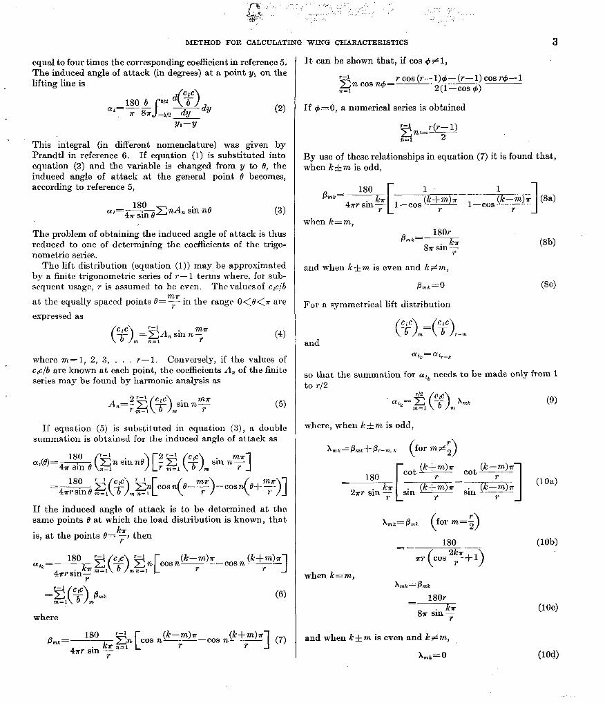
equal to four times the corresponding coefficient in reference 5. The induced angle of attack (in degrees) at a point y1 on the lifting line is -
180 b S b/Z d
ffi=-- - u 87r -b/2 dy dy (2)
Y1-Y
This integral (in different nomenclature) was given by Prandtl in reference 6. If equation (1) is substituted into equation (2) and the variable is changed from y to 0, the induced angle of attack at the general point 0 becomes, according to reference 5,
CY~=&~C~A, sin n0 (3)
The problem of obtaining the induced angle of attack is thus reduced to one of determining the coefficients of the trigo- nometric series.
The lift distribution (equation (1)) may be approximated by a finite trigonometric series of r-l terms where, for sub- sequent usage, r is assumed to be even. The values of c,c/b
at the equally spaced points 9=m< in the range o<e<u are
expressed as
(4)
where m= 1, 2, 3, . . . T- 1. Conversely, if the values of clc/b are known at each point, the coefficients A,, of the finite series may be found by harmonic analysis as
772 sinny (5)
If equation (5) is substituted in equation (3), a double summation is obtained for the induced angle of attack ai
If the induced angle of attack is to be determined at the same points e at which the load distribution is known, that
is, at the points e=k$, then
(Yig= 4*rly& ~l(~jm~+os n(k-rm)u-cos n (k+rm)u]
r
(6)
where
&k= 180 ku 272, [cos n(k-rm)u-cos n(k+rm’s] (7) 4~ sin --+- n=l
It can be shown that, if cos +#l,
r-1 Cn cos n+= r cos (r- 1)4- (r- 1) cos r+- 1 92=l 2(1-cos 4)
If I#J=O, a numerical series is obtained
r-1 r(r- 1) p=--F
By use of these relationships in equa.tion (7) it is found that, when k&m is odd,
1 -~ (k+mh l--cosh-m)~ (84 r r 1
when k=m,
pnk= 180;. 87~ sin r @b)
and when k&m is even and kfm,
PIIll;=
For a symmetrical lift distribution
so that the summation for CQ~ needs to be made only from 1 to r/2
(9)
where, when krtm is odd,
Xmk=Pmk+Pr-7% k (for rn$ij
180 cot (k+mh cot (k--mh
= 2ur sin ?
C
sin (k+Tm)~-sin (kym)r r r 1
(104
Xmk=Pmk (for m=ij
180 =-
when k=m,
180r = 8~ sin 5
and when k& m is even and k# m,
x mk =o
(lob)
(1W
(104)

4 REPORT NO. 8 6 5 .-NATIONAL ADVISORY COMiWITTEE FOR AERONAUTICS
For an ant.isymmetrical lift ,distribution
(a= -(% and
ffiJG=-~i,--k
In this case the summation for CQ, needs to be made only .I
=O; then 712 r 2 l ClC
ai,'E (> b Ylrlk ,nl=l m
where, when k&m is odd,
180 1 =- 27r1 (k+m)n- sin* ___ r 1
(11)
1 (124
when k=m,
Yrnk’ Pmll
= 18Or
8~ sin? Wb)
and when k&m is even and k#m,
yna= 0 (12c)
Multipliers can thus be calculated so that the induced angle may be readily obt,ained by multiplying the known values of c,c/b by the appropriate multipliers and adding the resulting products. The multipliers are independent of the aspect ratio and taper ratio of the wing. Tables I and II present values of firnx, and AmI; and -yml;, respectively, for
r=20. Similar tables for go AWLI; and goymn- are given in
TABLE I.-INDUCED-ANGLE-OF-ATT.4CK MULTIPLIERS pmk FOR ASYMMETRICAL LIFT DISTRIBUTIOKS ’
[ %=,z,( y),“@?“k]
\ \ \ 2.4 \ IF
-0.9877 -n. 9511 -0.8910 -0. 8090 -0. 70il -0.5878 --Il. 4540 -0.3O’Jo -0.1564 0
211 ___..______- -__-~- -__ ---. __-- ~~ __-- IL ’ I; m\ 19 18 17 16 15 14 13 12 11 10
\ ~~
-0.9877 19 915 651 -166.985 0 -7.019 0 -1.401 0 -0.486 0 -0.230 1 O.%i7 ______---__--___-________ ___ ___- ----.- -------
-. 9511 18 -329.859 463.533 -122.749 0 -7.438 0 -1.792 0 -. 701 0 2 .9511 _______~~_~___ -__--- __- --_______-
-. 8910 17 0 -180.336 315.512 -96. i3i 0 --i. Oi3 0 -1.920 0 -_ 819 3 .a910 ~--~~-~ ____ -__--__ __--
-. 8090 16 -26.374 0 -125.246 243.694 -81.067 0 -6.680 0 -1.97i 0 4 .a090 -__-__-- _--- __--- --_- __--
-. 7071 15 0 -17.020 0 -9;. 524 202.571 -71.139 0 -6.391 0 -2. n2G ~______-~ ____-__-- ___~
-_ 5878 14 --i. 246 0 -12.604 0 -81.392 lii. 054 -64. i35 0 -G. 228 0 --- ___- __ ~----__ --__ __-
-_ 4540 13 0 -5.166 0 -10.126 0 -il. 296 160.761 -fiO. i25 0 -6.192 7 4540 --~ -__- -- ----- __ ---- - ___-
-. 3090 12 -2.956 0 -4.022 0 --x. 396 0 -fvl. Bli 150.611 -58.514 0 8 .309G __~-__ ----_- -~--___--__ __--____
-_ 1564 11 0 -2. 241 0 -3.322 0 -i. 604 0 -60. iG8 145.025 --ST. 812 9 15R4 ____ ____- ----- --__ -~_-__-___~--__ ~---____-~-
0 10 -1.4m 0 -1.804 0 -2.865 0 -6.950 0 -58.533 143.239 10 0 ___- -__- ___-___ _-_- _-__-_-__-__--____
.1564 9 0 -1.153 0 -1.518 0 -2.554 0 -6.530 0 -5i. 812 11 -. 1564 _______~-~-- ----- -----______-- ~----__ __- ___-
.3090 8 -. 810 0 --.946 0 -1.319 0 -2.340 0 -6.288 0 12 -. 3090 ___-_--~-~ - ---- ----- ~____ ~-----__-~--
.4540 i 0 -. G4G 0 --.son 0 -1. Ii6 0 -2.192 0 -6.192 13 -_ 4540 _____---- ----- --_- --___ ___ ___--
.5878 6 -.46i 0 -. 530 0 -. 691 0 -1.068 0 -2.092 0 14 -. 5Si8 - -__- __- ----- -------__--__ __ --_-
ion 5 0 -_ 368 0 -_ 441 0 --.GO4 0 -.981 0 -2.02G 15 -_ iOi1 ______-___-----_-_ __-- __-
________
1 2 3 4 ___- ____--_---_--__-___.-___
.98i7 .9511 .a910 .809G '.iOll ) 6.S8i8 1 7.4540) ‘.iOLa) ‘.1564 ‘[?‘f’F\T,,,,
1 Vslues of I: at top to hr used with values of m at left side; valurs of I: at bottom to be used with values 01 m at right side.

-&?I, : <*b-e+. _I
,. ; _. ..,L, <., .:: : _- .&L ‘.
sr ’
METHOD FOR CALCULATING W ING CHARACTERISTICS 5
TABLE II.-INDUCED-ANGLE-OF-ATTACK MULTIPLIERS X,,zk FOR SYMMETRICAL LIFT DISTRIBUTIONS AND Y,,,~ FOR ANTISYMMETRICAL LIFT DISTRIBUTIONS
r \ \ ‘1
y / 0 1 0.1504 1 0.3090 1 0.4540 1 0.5878 1 0.7071 1 0.8090 1 0.3910 1 0.9511 1 0.9877
b Multipliers h.x
-
.3099 8
--I -58.533 lo--- 1 1 _~- 1 1 1 1 / -6.950 0 -2.805 0 -1.304 0 -1.4fi3
024 145.025 1 d7.298 ) 0 1 -10.158 1 0 1 -4.840 1 0 1 -3.394 1 0
0 4X.802 -I-
150.011 -67.157 I 0 ( -9.910 ) 0 / -4.908 ( 0 1 -3.768 --_-~ ___.- ___-- -~ -.--
3 7 -12.384 0 -62.917 100.701 -72.472 1 0 I -10.920 I 0 I -5.812 1 0 --~-- -.~- __- ~__-~ ~- -~
.5878 6
.7071 1--r ----4x-- ---~
.4541
I- ____________~~_ ~-
.8090 1 4 -26.635 --
.8910 1 3 j -180.528 1 0 _-- ___- --
.9511 1 2 I 403.533 I -329.976 -___ _----
.9877 / 1 / -1Gi. 045 I 915.051
___ __-- ~-~ .9511 I 2 1 -. 340 0 -1.567 0 -i. 277 0 ) -122. 019 403. 533 -329. 741
__- ,987; / I / 0 - 3.53 0 -1.311 0 -6 950 0 -106.926 915.051
r(~ferenccs 7 and 8, rcspcctivcly, but no derivation is given
thcrcin. Tables for Fzo p7,,t, f$, A,,,, and 27r 180 -fmr arc given in
rcfcrcnce 4 for values of r=8, 16, and 32. An inspection of tables I and II shows that positive values occur only on the diagonal from upper left to lower right and that almost half of the values are equal to zero. The multipliers Pmr and Xlnr may be used with either nonlinear or linear section lift data, whereas the multiplier% for ymk may be used only wit’h linear section lift dat,a.
section data for the appropriate airfoil section and local Reynolds number, values of c1 are read which correspond to the effective angle of attack of each section. If these values of cL do not agree with those originally assumccl, a second assumption is made for cl a.nd the process is rcpeatcd. Further assumptions are made until the assumed values of c1 are in agreement with those obtained from the section data.
WING CHARACTERISTICS
The method of determining the lift distribution becomes Once the lift clistribution of a wing has been determined, one of successive apprdxin-iations. For a given geometric the main part of the problem of calculating the wing char- angle of attack, a distribut,ion of c1 is assumed from which acteristics is completed. The induced-drag and induced- the load distribution c,c/b is obtained. The incluced angle yawing-moment coefficients are entirely dependent upon of attack is then determined by equation (6), (9), or (11) the lift distribution and it is assumed that the section profile- through the use of the appropriate multipliers and sub- drag and pit.ching-moment coefficients are the same func- tracted from the geometric angle of attack to give the tions of the lift coefficient at each section of the wing as effective angle of attack at each spanwise station. From those determined in two-dimensional tests.

6 REPORT NO. 8 6 5 .-NATIONAL ADVISORY COMMITTEE FOR AERONAUTICS
The calculation of each of the wing coefficients involves a spanwise integration of the distribution of a particular
function f 7 0
. This integration can be performed numeri-
cally through the use of additional sets of multipliers which are found in the following manner.
If
f ($y)=f( cos 0) =ZA, sin n0
then
Since the values of j 0
F are determined at the points O=m+J . A, can be found by harmonic analysis a,s in equation (5)
Al=; i$,.f (F)msin F
Therefore
J:lf(zhY>d (F)=F gl f(2f)msin F
=&lf(~)m%z (134
where rn7r
qm=& sin 7
If the distribution is symmetrical, f 2q ( b >m=f(?)r2n(l
J-lf(3 d(F)=2 li?143m 7777s (13b)
?1 -27lnl WS- ( >
rn#G
qms-= qm ( >
m=r 2
where
The moment of the distribution f 9 can be found in a 0 similar manner
~~lf(~)(~)d(~)=~‘(ZA,sin~e)~ine~~~ede
(144
where 2mr urn=& sin 7
If the distribution is antisymmetrical, f (““l= -f (5),_, J-
sl,f(T)(4)d(%)=4~~~(~)~0,, (14b)
TABLE III.-WING-COEFFICIENT MULTIPLIERS
I 2Y 7;
m ‘Im nm Cm Cm.3 !
--__ IL- ~__
-0.9877 -_ 9511 :i -. 8910 li
--.8090 -. 7071 :: --.6878 14 -. 4540 13 -. 3090 12
-. 1564 0 :i
: :ii 8”
.4540 .5878 i
.7071 5
.809a
.8910 i
.9511 2
.98ii 1
where u -22a, ma-
Values of rlrnr vrns, urn, and uma are given in table III for r=20.
0.07854 .I5515 .I4939 .139+6 .12708
:Ei .07131 .04854 .02457
-0.00607 -. 01154 -. 01589 -. 01867 -. 01964 -. 0186i -. 01589 -.01154 -. c?!ml7 0
.00607
.01154
.01589
.01867
.01964
.01867
.01589
.01154
.00607
0 .01214 .02308 .03177 .03735 .03927 .03735 .0317i .02308 .01214
--
Wing lift coefficient.-The wing lift coefficient is obtained by means of a spanwise integration of the lift distribution,
For asymmetrical lift distributions
(15a)
For symmetrical lift distributions
(15b)
Induced-drag coefficient.-The section induced-drag co- efficient is equal to the product of the section lift coefficient and the induced angle of attack in radians,
The wing induced-drag coefficient is obtained by means of a spanwise integration of the section induced-drag coefficient multiplied by the local chord,
S b/2 cDi=i -b/2 180 =lccv dy A CT ;l!?f!=!d(~) S

~ .:$$ETHOD FOR CALCULATING WtVING CHARACTERISTICS .J 7
For asymmetrical lift distributions For asymmetrical lift distributions
For symmetrical lift distributions
(16b)
ProAle:drag coefficient.-The section profile-drag coefh- cient can be obtained from section data for the appropriate airfoil section and local Reynolds number. For each span- wise station the profile-drag coefficient is read at the section lift coefficient previously determined. :. The wing profile- drag coefficient is then obtained by means of a span&se integration of the section profile&drag coefficient multiplied by the localchord, :
i_ S
b/2 %=; -b,2 Cd,,0 dy
For asymmetrical lift distributions
: (174
For symmetrical lift distributions
cDQ=mzl (Cd,, ;) qrns m
, (17b)
Pitching-moment coefficient.-The section pitching-moment coefficient about its quarter-chord point can be obtained from section data for the appropriate airfdil section and local Reynolds number. For each spanwise station the pitching- moment. coefficient is read at the section lift coefficient previously determined and then transferred to. the wing reference point by the equation
---Icl sin (C%--cr()-c+, cos (&-Crt)] 08) __
“phere-x and z are measured from the wing reference point to the - quarter4hord point of the: seb6ioh under consideration,
‘and-upward and backward forces and distances are taken as positive. The section pitching-moment coefficient about its aerodynamic center may be used instead of G+,~, in which case x and z are measured to the section aerodynamic center. The term cd0 sin (&T(Y;) may usually be neglected. The wing pitching-moment coefficient is obtained by the spanwise integration
L .~,~7~56--494 ‘. ” .(. ,_ /.,.’ -..:“.,y- ., . _ . j; ;; .,, _‘. :
‘: :. .C‘-
For symmetrical lift distributions
W’b)
Rolling-moment coefficient.-The rolling-moment coeffi- cient is obtained by means of a spanwise integration
(204
For an antisymmetrical lift distribution
Induced-yawing-moment coefficient.--The induced- yawing-moment coefficient is due to the moment of the induced-drag distribution,
A' S CIc rfft 3, d 2y --- =4 -1 b 180 b 0 7
(21)
The induced-yawing-moment coefficient for an antisymmet- rical lift distribution is equal to zero and has little meaning inasmuch as the lift coefficient is also zero. The induced- yawing-moment coefficient is a function of the lift and rolling- moment coefficients and must be. found for asymmetrical lift distributions..
Profile-yawing-moment coefficient.-The profile-yawing- moment coefficient is due to the moment of the profile-drag distribution,
.C -A’ S b’2 @$ dy nQ sb-b/z _. : .-'- =!$lT 7 d @)
_‘, (22)
A'~PLICATIONOFMETHODUSIN~~NONLINEARSECTION~JFT DATA FOR SYMMETRICAL LIFT DISTRIBUTIONS .
The method described is applied herein to a wing, the geometric characteristics of which are given in table IV. Only symmetrical lift distributions are considered hereinafter inasmuch as these are believed to b-e sufllcient for illustrating . <
-.-. .: ._., -. . . ..; . ._
j -..------ .-..111-1-m a.....- _..-. ..._.---__-__--__ - -... _. . . . . . . . ._ --.-- ._.. -_--.-

8 - REPORT NO. 8 6 5 .-NATIONAL ADVISdRY COMMITTEE FOR AERONAUTICS
TABLE IV.-GEOMETRIC CHARACTERISTICS OF EXAMPLE WING . Taper ratio, c.lcr _____ ____________________ -- __________..____________________________-
10% Root section..--- __________._____________________________.--------------------- NACA 4420
Aspect ratio, A __________ _______ ________________________________________----------- Tip section _____ ________________________________________---------------------- NACA 4412 Span, b,ft.---- ______ --- ____ -_- ________________________________________---.-------..- 15.00 -3.50 Area, S,sqft- ___.______ __- ______ -_- _____ __________.._____. L ___..______-_____-_ - -___ 22.39
Qeometric twist,.er, deg .__________________’ ______________._________________________-- Aerodynamic twist, (I’, deg ________________________________________.----------------- -3.40
Root chord, c., ft ____ -- ________ ____________ -- ____________________-----------.------- 2.143 Edge velooityfactor,E.---..-----.-------------------------------------------.------ 1.044 Meangeometricehord,4ft _._____.._______.___ ____ --_- _________ _______ ___________ 1.493 Wing Reynoldsnumber,R.--..------.------..----------------------------------- 3.49X10@ Meanaerodynsmicchord,c’,ft ______ -- ____ -- __________._____.._____________________ 1.592 a,,,deg...--.---------------.------.----------------------.------------------------- -3.90
.
c ( e, deg ( t‘. deg / c,
1.932 0.01335
.01260
.01138
.01023
.00917
.00822
0
.0690
.1517
.2496
0 0. 200 4.7OXloe 1.0000
.I564 ,195 xi------- .9062
.3090 ,163 3.---- .8146
.4540 .180 -------XT 3.42
1.24 -.235 -
-.53 -. 516
----zG-- -.849 -____
-1.27 -1.235
----zx- -1.670
----xi- -2.138 -___
-2.68 -2.604 -____
-3.10 A3.013
.1295 1.303 -___
- .1164 1.169 -____
- .1040 1.044 -____ -
.0925 .929 -____
- .0323 ,826 -___-___-
.0735 ,739
1.022
.a09
,640
1 .5878 1 .171 13.041.6473 .3632 ~~ .7071 ,161 2.70 .5757
~___ -6090 .150 2.42 .5146
___~ .8910 ,139 2. 18 .4654
~- _______ .9511 ,129 2.02 .4293
.4913
,512 .00740 .6238
-1.06651 ,663 I- ,418 .7658
,356 .8862 -__-____
.9677 .I23 1. 44 .3061 .09446 I I I
For tapered wings with straight-l$e elements fr ‘orn root to construction tip:
+( 12) t (Alter values of c/c, near tip to allow for rounding.) . (Use value of c/c, before rounding tip.)
for the geometric angles of attack. This equation weights the lift distribution according to the average of the chord distribution of the wing under consideration and that of an elliptic wing of the same aspect ratio and span. When the lift distributions at several angles of attack are to be computed and after they have been obtained for two angles, the initially assumed cz distribution for subsequent angles can be more accurately estimated in the following manner: Values of downwash angle are first estimated by extra- polating from values for the preceding wing angles, and then, for the resulting effective angles of attack, the lift’ coefficients are read from the section curves.
The lift coefficients in column @ of table V, read from section lift curves for the effective angles of attack, will usually not check the assumed values for the first approxima- I tion. In order to select assumed values for subsequent ap- proximations, the following simple method has been found to yield satisfactory results. An incremental value of lift coefhcient Acl m is obtained according t,o the following relation
the method of calculation. The lift, profile-drag, and pitching- moment coefficients for the various wing sections along the span were derived from unpublished airfoil data obtained in the Langley two-dimensional low-turbulence pressure tunnel. The original airfoil data were cross-plotted against Reynolds number and thickness ratio inasmuch as both varied along the span of the wing. Sample curves are given in figures 1 and 2. From these plots the section character- istics at the various spanwise stations were determined and plotted in the conventional manner. (See fig. 3.) The edge-velocity factor E, derived in reference 9 for an ellipt,ic wing, has been applied to the section angle of attack for each value of section lift coefficient as follows:
LIFT DISTRIBUTION
Computation of the lift distribution at an angle of attack of 3’ is shown in table V. .This table is designed to be used where the multiplication is done by means of a slide rule or simple calculating machine. Where calculating machines capable of performing accumulative multiplication are avail- able, the spaces for the individual products in columns @ to @ may be omitted and the table made smaller. (See tables VII and VIII.) The mechanics of computing are explained in the table; however, the method for approxi- mating the lift-coefficient distribution requires some explana- tion. The initially assumed lift-coefficient distribution (column @ of first division) can be taken as the distribution given by the geometric angles of attack but it is best deter- mined by some simple method which will give a close approxi- mation to the actual distribution. The initial distribution given in table V was approximated by
where circled numbers represent column numbers in table V and where K has the following values at the spanwise stat,ions
1 I
I 2Y 5
I K
I
and (@-@)n is the difference between the check and as- sumed values for the mth spanwise station. The incre- mental values so determined are added to the assumed values in order to obtain new assumed values to be used in the next approximation. This method has been found in practice to make the check and assumed values converge in about where c1 (O, is the lift coefficient read from the section curves

METHOD FOR CALCULATING WING CHARACTERISTICS 9
(a) Lift. (W Drsg. (c) Pitching moment.
FIGURE l.-Vnriat& of chsrncteristics of NAGa 4421 airfoil with Reynolds number. (Similar curves plotted for each thickness ratio.)
three approximations if the first approximation is not too much in error.
WING COEFFICIENTS
Computations of the wing lift, profile-drag, induced-drag, and pitching-moment coefficients are shown in table VI. Since the lateral axis through the wing reference point con- tains the quarter-chord points of each section, the x and z distances in equation (18) are zero, and the pitching-moment
.8
=I
.6
.0/6
-.04
I! I!! !!! ! !!! !-! I -.,$I I I I I I I I I I I I I 1
/4 /6 18 20 22 24 26 t/c
(a) Lift. (b) Drag. (c) Pitching moment.
FIGURE 2.-Variation of characteristics of NACA 44-series airfoil with thickness ratio.
R=4.70X10⁶;~=0. (SimilarcurvesplottedforReynoldsnumbcrscorresponding toeechstation.)
coefficient of the wing is determined solely by the values of Cw4.
APPLICATION OF METHOD USING LINEAR SECTION LIFT DATA FOR SYMMETRICAL LIFT DISTRIBUTIONS
Although the method described herein was developed particularly for use with nonlinear section lift data, it is
I 11111II.II.I.I~~,.-III ..I. mm.--..- ----- _-

10 REPORT NO. 865.-NATIONAL .ADVIt+ORY COMMITTEE FOR AEROhAUTICS
readily adaptable for use with linear section lift data with a in tables VII to X for the wing, the geometric characteristics resulting reduction in computing time as compared with of which were given in table IV. most existing methods. When t.he section lit curves can be It should be noted that tables VII and VIII are essentially assumed linear, it is usually convenient to divide any the same as table V but are designed primarily for use with symmetrical lift ,distribution (as in reference 10) into two calculating machines capable of performing accumulative parts-the additional lift distribution due to angle-of-attack. multiplication. If such machines are not available, these changes and the basic lift distribution due to aerodynamic tables may be constructed similar to table V to allow spaces twist. The calculation of these lift distributions is illustrated for writing the individual products.,
I.2
0 / / / i / / / / / /' / / / / /
-'$' -4 0 4 8 I2 I6 20
/ 1 /'
0 0 0 0 0 0 0 0 0 Effec the ong/e of attack, C&
(a) Lilt,. FIGU~JE 3.-Section characteristics of example wing.
I I I I I I I I I I I I I I I I
I.4 $Lo 'I l Q/564-- 0.3090~-0.4540 0.5878__0.707/_-0.8090--0.89/O--0.95/f--0.9877
R= 470x106 4.26x/06 3.83~106 342x IO= Z7OxfO~ 2.42xX/06 2.18x10⁶ 2.02xlO~ /.44x/06
(b) DrBg. _. ‘-
FIQURE 3.-Co&irmed. -

METHOD FOR CALCULATING WING CHARACTERISTICS 11
.
(c) Pitching moment.
FIGURE 3.-Concluded.
LIFT CHARACTERISTICS b Two lift distributions are required for the determination
of the additional and basic lift distributions. The first one is obtained in table VII for a constant angle of attack (e/=0) and the second one in table VIII for the angle of attack distribution due to the aerodynamic twist (LY,~= 0). The check values of clc/b (column @) are obtained by multi- plying the effective angle of attack (Y, by a&b. The final
approximations are entered in table IX as ‘2 b
( >
( > (%8) and
Y (S,‘)’
The y (LlQ ‘0 distribution is the additional lift distribu-
tion corresponding to a wing lift coeflicient C,,,, ) determined s in table IX through the use of the multipliers vms. It is
usually convenient to use the additional lift distribution C,@j2 -- -
b corresponding to a wing lift. coe5cient of unity. This
distribution is found by dividing the values of ‘2 ( > 6 (aas)
by c”(mas,.
The * ( > b (*r3
distribution is a combination of the basic
lift distribution and an additional lift distribution corre- sponding to,a wing lift coe5cient CL (~13 also determined in
_-. -. table IX. The basic lift distribution CT is then determined
._._._ -. ..-_ .^.
by subtracting the additional lift distribution y CL(tl,)
Inasmuch as the wing lift curve is assumed to be linear, it is defined by its slope and angle of attack for zero lift which are also found in table IX. The maximum wing lift coefficient is estimated according to the method of refer- ence 10 which is illustrated in figure 4. The maximum lift coe5cient is considered to be the wing lift coe5cient at which some section of the wing becomes the first to reach its maximum lift, that is, clb+CL c~~~=c~,~~. This value of CL is most conveniently determined by finding the minimum value of Czmaz-CzO
>...
“al along the span as illustrated in table IX.
-. I
INDUCED-DRAG COEFFICIENT
The section induced-drag coefficient is equal to the prod- uct of the section lift coefficient and the induced angle of attack in radians. The lift distribution for any wing lift coe5cient is
_ *: (23)
The corresponding induced angle of attack distribution may I& written as. I.
- --. R=%JL+ab (24)

TABLE V.-CALCULATION OF LIFT DISTRIBUTION FOR EXAMPLE WING
(I et al ClC T (a+4 sii!& ii -ti-
XdX@ (&
(TableIV) (@X0) 0 .1564 .3090 .4540 .5676 .7071 .6090 .8910 .9511 .9677 & m---- -~- __---
143.239 -56.533 0 -6.950 0 -2.865 0 -1.804 0 -1.468 0 ~-
3.00 0.513 0.1429 0.0733 10.50 -4.29 0 -.51 0 -.21 0 -.13 0 -. 11 1.38 ------- --
-115.624 145.025 -67.298 0 -10.158 0 -4.840 0 -3.394 0
.1564 2.76 .517 .1295 .0670 -7.75 9.72 -4.51 0 -. 68 0 -.32 0 -.M 0 .98 ___---____- -- -
0 -64.802 150.611 -67.157 0 -9.916 0 -4.968 0 -3.768
.3090 2.47 .523 .11&4 .0609 0 -3.95 9.17 -4.99 0 -. 60 0 -.30 0 -. 23 :90 ~---- __-
-12.384 0 -62.917 160.761 -72.472 0 -10.926 0 -5.812 0
.4540 2.13 .519 .1040 .0540 --.67 0 -3.40 3.63 -3.91 0 -. 59 0 -. 31 0 .77 s------ -A--- -- -- L ‘3 0 -8.320 0 -65.803 177.054 -82.083 0 -13.134 0 -7.713
B ‘ii .5878 1.73 .501 .9925 .0463 0 -.39 0 -3.05 3.20 -3.80 0 -.61 0 -.36 .eQ
& ~.----~ ~-- ~---
i? -4.051 0 -7.372 0 -71.743 202.571 -97.965 0 -17.388 0
2 ~----- .7071 1.28 .477 .0823 .0393 -.16 0 -. 29 0 -2.82 7.96 -3.85 0 -. 63 --- .65 0
‘Z 0 -2.880 0 -7.208 0 -81.434 243.694 -125.537 0 -26.635
.8090 .80 .430 .0735 .0316 0 -. 09 0 -. 23 0 -2.57 7.70 -3.97 0 -. 84 .5e ~~- ------
-1.636 0 -2.371 0 -7.370 0 -96.962 315.512 -180.528 0
.6910 .32 .360 .0%5 .0239 -.04 0 -.06 0 -. 18 0 -2.32 7. 54 -4.31 0 .42 ___--- -__
0 -1.062 0 -2.016 0 -7.599 0 -122.680 463.533 -329.976
.9511 --.lO ,231 .ffi13 .0172 0 --.02 0 -. 93 0 -.13 0 -2.11 7.97 -5.68 .7i --_-_____-~ ~_
-.459 0 -.620 0 -1.491 0 -7.089 0 -167.045 915.651
.9877 -.39 .22a .0437 .0100 0 0 --.Ol 0 -.Ol 0 -.07 0 -l.67 9.16 1.94 -2.33 .I65 -- -,-II-I ---2 I 1.38 .98 I .w I .77 I-71 .65 I .55 1 .42 .77 1.94 lr---’ =
143.239 -58.533 0 -6.950 0 2.865 0 -1.804 0 -1.468
0 3.09 0.498 0.1428 0.0x2 10.20 -4.17 0 --.49 0 -.20 0 -.I3 0 -. 10 1.61 1.39 .491 ~--- ---
-115.624 145.025 -87.298 0 -10.158 0 -4.840 0 -3.394 0
.1564 2.76 .516 .1295 .OtH3 -7.12 9.69 -4.50 0 -. 68 0 -.32 0 --.23 0 1.07 1. I39 .623 ~-- -- ---
0 -64.802 150.611 -67.157 0 -9.916 0 -4.968 0 -3.768
.3090 2. 47 .524 .I164 . 0610 0 -3.95 9.19 -4.10 0 -.60 0 -.30 0 --.23 .95 I.62 .617 -- ---
-12.384 0 -62.917 160.761 -72.472 0 -10.926 0 -5.812 0
8 .4540 2.13 .517 .1040 .0538 --.67 0 -3.38 8.65 -3.99 0 --.59 0 --.31 0 .74 1.39 .517
‘3 ----- -- B 0 -8.320 0 -65.803 177.054 -82.083 0 -13.134 0 -7.713 ‘iz 0 .5878 1.73 .500 .0925 .0463 0 -.39 0 -3.06 3.20 -3.80 0 -.61 0 h---------
-.36 .@I 1.13 .m 3 -4.051 0 -7.372 0 -71.743 202.571 -97.965 0 -17.388 0 .--
z .7071 1.28 .478 .0823 .0393 -.16 0 -. 29 0 -2.82 7.96 -3.85 0 -. 68 8 ~------
0 .5s .70 .480 ~_--__
$ 0 -2.680 0 -7.208 0 -81.434 243.694 -125.537 0 -26.635
-
_-
_.
-.
_.
-.
-.
, -.
,
1
I -
L
0 0 ---
Check to%?, Cl
----
1.12 0.464 --
-- .8090 .30 .441 .0735 .0324 0 -.99 0 -.2.3 0 -2.94 7.90 -4.07 0 -.36 .61 .19 .443
~----- --- -1.638 0 -2.371 0 -7.370 0 -96.962 315.512 -180.528 0
.6910 .32 .382 .9665 .0254 -.04 0 -. 06 0 -.19 0 -2.46 8.01 -4.59 0 .70 -.33 .386 ~-
--- - - 0 -1.062 0 -2.016. 0 -7.599 0 -122.880 463.533 -329.976
.9511 -. 10 .292 .cfl13 .0179 0 -.02 0 --.04 0 -.14 0 -2.20 8.30 -5.91 .I39 -.99 .312 ----__---
-- -.459 0 -.620 0 -1.491 0 -7.089 0 -167.045 915.651
.9877 .2!m
--.39 .219 .0437 .0096 0 0 -. 01 0 -.Ol 0 -.07 0 -1.60 8.79 1.33 -1.72 --
z 1.61 1.07 .95 .74 .60 .58 .61 .70 .89 I. 33
,

-
-
1 0 / 3.00 1 0.487 / o.14m 1
2.76 1 .517 1 .1295 j .1564 1
j .3090 / 2.47 1 .522 / .1164 1
.4540 2.13 .516 .1040 --____
.5676 1.73 ,500 .0825 ----_
.7071 1.28 .479 .0823 y-p-_
143.239 -56.533 0 -6.950 0 -2.665 0 -1.604 0 -1.466
0.0710 10.17 -4.16 0 --.49 0 --.20 0 .13 0 -.lO 1.56 1.45 .497
1 ---
--I 15.624 145.025 -67.298 0 -10.156 0 -4.640 0 -3.394 0
.0670 -7.75 9.72 1 -4.51 0 -.68 0 -.32 0 -.23 0 1.12 1.64 .518
1 .6090 1 .SO 1 .443 1 .0735 /
.6910 .32 .385 .0565 ----_ I-
L
.9511 -.lO .299 .0+x3 ----_
.9677 -.39 ,224 .@a37 -~----____
-- 0 -64.602 150.611 -67.157 0 -9.916 0 -4.968 0 -3.760
.0608 0 -3.94 9.16 -4.08 0 -.60 0 --.30 0 -.23 .91 1.56 .521 ---
-12.384 0 -62.917 160.761 -72.472 0 -10.926 0 -5.612 0 ~-
.0537 -.67 0 -3.38 8.63 -3.89 0 -.59 0 --.31 0 .74 1.39 .517
0 -6.320 0 -65.803 177.054 -02.003 0 -13.134 0’ -7.713
.0-403 0 --.39 0 -3.05
8.20 -3.80 0 -.61 0 -.36 .oo 1.13 .m ---
-4.051 0 -7.372 0 -71.743 202.571 -97.965 0 -17.360 0 1 I
.0394 -.16 0 --.29 0 -2.83 7.98 -3.80 0 -.69 0 .59. .479 .69
-- -- 0 -2.660 0 -7.206 0 -81.434 243.694 -125.537 0 -26.635
.0326 0 -.OO 0 -.2.3 0 -2.65 7.94 -4.99 0 -.87 .62 .I8 .442
-1.636 0 -2.371 0 -7.370 0 -96.962 315.512 -180.528 0 i-
.0256 --.04 0 -.06 0 -.19 0 -2.48 8.98 -4.62 0 A70 -.38 .386
-.459 0 -.620 0 -1.491 0 -7.089 0
.0098 0 0 --.Ol
O.74
-.Ol
9,
-.07 0 -‘:.z” 1 gl:::;l
1
/,Ti
c 1.55 1.12 .91 .al 1 .62 .70 .99 I 1.37 I--
TABLE VI.-CALCULATION OF WING COEFFICIENTS FOR EXAMPLE WING
[A=10.05; a.=3.00]
.m -
.224 --
w CIC Multipliers 7
57.3+c (CT& 7 cr Cd@ C Cd& C, C’ 4
b F T B C-C 7-a
(Table V) (Table V) (OX@) (Table V) ‘W&
(Table IV) (OX@) ‘EM&
(Table IV) (0X0) ~~-____
0 .07654 0.0710 1.55 0.1101 0.497 0.0077 1.435 0.0110 -0.081 1.932 -0.156 --- ~-___ .1564 .15515 .0670 1.12 .0750 ,517 ,067s 1.300 .OlOl -. 081 1.586 --.128
--- .3090 .14939 .064l8 .91 .0553 ,522 .0076 1.169 .OQ89 --.081 1.282 -. 104
----____ .4540 .13996 .0537 .74 .0397 ,516 .0076 1.044 . OQ79 -.082 1.022 7084
.5878 .12706 .0403 .60 ,027s ,500 .9976 ,929 .0071 -.985 ,809 -.069 ___--
.7071 .11107 .0394 .59 .0232 ,479 .0976 ,826 .cc63 -. 090 .640 -.058 ---____, --~~___
A4090 .09233 .a326 .62 .0202 ,443 .0076 .739 .0956 -.092 ,512 -. 047 ----- --
.6910 .07131 .0256 .70 .0179 ,385 .0076 ,668 .0051 -. 692 .418 -.038 ____-- -- -~--- -___
.9511 .04854 .0183 .99 .0181 ,293 .9976 .616 .Gu47 -.992 ,356 -.033 ---F-P ____-___
.9877 .02457 .0098 1.37 .0134 ,224 .0079 ,439 .OQ35 -.091 .181 -. 016
c!e=z(@x@)=-o.@34 I
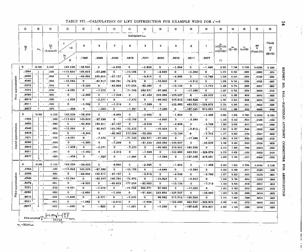
TABLE VII.-CALCULATION OF LIFT DISTRIBUTION FOR EXAMPLE WING FOR l ‘=O I
0 0 0
---
0 10.000 0.1107 ~-
-
_
-I
-.
_.
-.
-.
-.
-.
-.
-.
-1 =
-.
-.
-.
-.
-. , -
-
=
-.
-.
-.
_.
_.
_.
-
2Y /’ ,>‘O .1564 .3090 .4540 .5878 .7071 .8090 .8910 .9511 .9877
(9 ~- -~ ~--______
143.239 -58.533 0 -6.950 0 -2.865 0 -1.804 0 -1.468 2.202 7.798 0.7556 0.01385 0.1080 -__ ___-
-115.624 145.025 -67.298 0 -10.158 0 -4.840 0 -3.394 0 1.475 8.525 .8295 ---Gir------- .1074 ----___
0 -64.802 150.611 -67.157 0 -9.916 0 -4.968 0 -3.768 1.356 8.644 .8454 .01138 .0984 --_-___
-12.384 0 -62.917 160.761 -72.472 0 -10.926 0 -5.812 0 1.236 8. 764 .8624 .01023 .c@97 -__ ~-~___~
0 -8.320 0 -65.803 177.054 -82.083 0 -13.134 0 -7.713 1.226 8.774 .8095 .a0917 .0805 ~_---___~
-4.051 0 -7.372 0 -71.743 202.571 -97.965 0 -17.388 0 1.257 8.743 .8734 .00822 .0719 -__ -~ -- ~- --___~
0 -2.880 0 -7.208 0 -81.434 243.694 -125.537 0 -26.635 1.411 8.589 .84x9 .ciQ740 .0636 ___- -~~
-1.638 0 -2.37.1 0 -7.370 0 -96.962 315.512 -180.528 0’ 1.787 8.213 --I_
.8328 *cm374 .0554 --___-
0 -1.062 0 -2.016 0 -7.599 0 -122.880 463.533 -329.976 3.754 6.246 .6371 .00625 .0390
-.459, 0 -.620, 0 I -1.4911 0 I -7.089 1 0 -167.045 1 915.651 I---------- 8.012 1 1.988 .!zmo .W446 .0089
.1050 -____
.0982
.1564
-~ .0904 _-___ .0819
,072s -~
.0632
-.0533
I .0434
1 .0275
I I 0 I 10.000 I 0.1103 ‘143.239 ‘58.533 0 -6.950 0 -2.865 0 -1.804 0 -1.468 2.094 7.006 0.7661 0.01385 0.1095
~-___~ -115.624 145.025 -67.298 0 -10.158 0 -4.840 0 -3.394 0 1.55s 8.442 .8214 .012&l .16+X
___- 0 -64.802 150.611 -67.157 0 -9.916 0 -4.968 0 -3.768 1.392 8.608 .a419 .01138 .0980
---- -12.384 0 -62.917 160.761 -72.472 0 -10.926 0 -5.812 0 1.213 8.787 .8646 .01023 .0899
1 .1055 .1564 ___-
B .3090 .s ___- B .4540
72 e
.5878-- ---
3 .7071 ____-
.0985 -~
.0901 -.- -----
0 -8.320 0 -65.803 177.054 -82.083 0 -13.134 0 -7.713 1.177 8.823 .8744 .00917 .0809
-4.051 0 -7.372 0 -71.743 202.571 -97.965 0 -17.388 0 1.205 8.795 .8786 .om22 .0723 -___ ~- -- --~
0 -2.880 0 -7.208 0 -81.434 243.694 -125.537 0 -26.635 1. 520 8. 480 .8539 .00740 .0528 ___- ~~- -1.638 0 -2.371 0 -7.370 0 -96.962 315.512 -180.528 0 2.114 -- 7.886 .7996 .Oc674 .0532
I .0813
I .07%
.0634 -___
.0531
.0411 -___
.0232
00 I 0.1102 I 0 1c
r/ -lo.158 1 0 1 -4.840 i 0 1 -3.394 1 0 ~1.602~8.398~.8171~.01260~.1068
143.239 j -58.533 0 -6.950 1 0 1 -2.865 1 0 1 -1.804 1 0 1 -1.468 ( 2.060 1 7.940 1 0.7694 1 0.01385 0.1100
-
1
-115.624 145.025 -67.298
0 -64.802 150.611 -67.157 1 0 -12.364 -:.320 -62.917 160.761 -72.472 -;.,,, 1
0 1 - 0 -65.803
.01138 .0981 --
.01023 .OOOO
I.C
.1564- Fl .,o .3090- 2 a .4540- ‘R e .5878-- &; T-xiT- 03: -- a .a :’ .8090 E. ___- E .a910
/ .105-i .0984
I .0893
I .0811 I .0722 --
.0632 -/-
.0534
(TiEiF/- I .0411
01 -1.491 1 0 1 -7.089 1 0 I-167.045 1 915.651 ~~~~~~~S~+
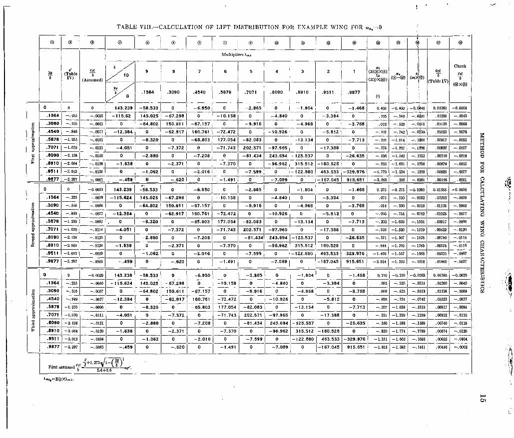
TABLE VIIT.-CALCULATION OF LIFT DISTRIBUTION FOR EXAMPLE WING FOR a.,=0
Multipliers A,,,,
Check
-- -72.472 0 -10.926 0
-.oG97 , 0 -- ----
-- -_-- ___ .8090 -2.138 -. 0125 0 -2.880 0 -7.208 0 -81.434 243.694 -125.537 0 -26.635 ~-
---p-pppp ----- .8910 -2.604 --.0124 -1.638 0 -2.371 0 -7.370 0 -96.962 315.512 -180.528
-- ___, .9511 -3.013 -1.456 -1.557
-67.157 I-.>---9.916 0 __-
-62.917 160.761 -72.472 0 -10.926 0 -5.812 0 --.095 -.784 -.0742 .01023 -.@a77 -__-____.~- ___--
-65.803 177.054 -82.083 0 -13.134 0 -7.713 ~- --.a7 -1.028 -. 1019 .lwJ17 -.COQ4 ----~ _____ ___-
-71.743 202.571 -97.965 0 -17.388 0 -.331 --1.339 -.133& .00822 -.OllO ____--__-___-.___~---- __- ~-______
-81.434 243.694 -125.537 0 -26.635 -.554l -1.583 -. 1599 .oG740 -. 0118 __- -~ ---- ____.

16 REPORT NO. 8 6 5 .--NATIONAL ADVISORY COMMITTEE FOR AERONAUTICS
TABLE IX.-CALCULATION OF LINEAR LIFT CHARACTERISTICS FOR EXAMPLE WING [A= 10.05; ar.,=lO.OO; y=-3.901
0 0.07854 0.1102 0.1323 -0.0029 -0.0105 0.0076 0.1429 0.926 0.053 1.421 1.477 - -----_ -_- -___ __-____ ___---___
.1564 .15515 .1057 .1269 --.a040 -. 0100 .0060 .I295 .9so ,046 1.418 I. 400 _-__- _ -_-- _______ _--- -
.3090 .14939 .0984 .1181 -.0057 -. 0093 .0036 .1161 1.015 .031 1.423 1.371 _-__ ____ __- --- ~___~--
.4540 .13996 .0899 .I079 -.0077 - 0085 .0008 .I040 1.038 INJS 1.432 1.372 -- _---- __- -___ ________~~_~ _____ -----
.5878 .12708 .0811 .0974 -. 0096 -.0077 -.a019 .0925 1.053 -.a21 1.441 1.388 __- -__
.7071--.liiF .0722 .086i -. 0111 -.OOBS --.0043 .0823 1.053 --.a51 1.436 1.412 __- --___-___--
.8090 .09233 .0632 oi59 -.0121 --.0060 --.0061 .a735 1.033 083 1.418 1.453 ____-
.8910 .07131 .0534 .0641 -. 0120 -. 0051 -. 0069 0665 964 104 1.404 1.564 ____ ____ ______ _____ _____ -___-_ -___- ------ _---- _-- -- I__ _--
.9511 .04854 .a411 .0493 -.0104 -. 0039 --.0065 .0613 ,804 -.106 1.419 1.897 ____ _ ______ __ _-___ -_----_ --_--- ------ ------ ----- ------ --;- ---
.9877 .02457 .0232 .0279 -.0063 --.0022 --.OOIl .013i ,635 -. 094
cL ("5) =Az(@xO)=o.sar, CL ,e,‘) =AZ(@X@) = -0.Oi9
a=cI.0?Lo,n,33 -cr. ('(')
= __- =o.gj aQ*( L-0) cl
*a,
CL,", =Min. value in @=1.37 ~,(L-O, =q*+% (,,-;! =--2.95
TABLE X.-CALCULATION OF ISDUCED-DRAG COEFFICIEXT FOR ESAlIPLE WISG
[A= 10.05; c+J =o.s33; CI.(.,,) = -0.079]
aid CLJlC 2Y Multipliers Ui(“Q ~i(,,.) TJq,,.) ai*
7 a nma
(Table VII) (Table VIII) (@XCq,/,) (Q-O) (Table IX) -___ ,____~__
0.07854 / 2.060 0.1323
.15515 I 1.602 -.-12fi9--.
.3090
.4540
.!a78
0.3273 _I o.Oi24 0.0031
.2442 I .0416 .0014
.1952 .0225 .0005 __--_ - __-
1559 .0032 n
---’ ______ --__--- .7071 .11107 1.218 1. 4w --.331 --.I16 --.215 .086i ---__ ____ __-- -__- -- - .8090 .09233 1.492 1.792 -.550 -.142 -.408
--(- .n759
____ __-__-____- .8910 .07131 2.111 2.535 -.830 -.200 -.630 .0641 __- ---- -___ .9511 .04854 3.399 4.081 -1.351 --.322 -1.029
---_I_ .n493
~~-~~~ ____ --___ ---.- .9877 .02457 4.840 5.812 -1.915 -.459 ) -1.456 j--=;--r--.0041-
.0008 -~
-. 0019 --__
--.0042 ___.
--.0061 -___
- .0069 .-__
-.0065
----- __--____ ,1359 -. 0121 .0002
-<iii-- --.0248 / .0009
__- --_'-- .I625 j --.05i9 .0013
.0067 .2012 ) -.0X3
.1622 ) -.0645 1
____
.0060 1 I I
c”;=(~~~)cL2+(~)cL+*~~ =o.n322cL*-n.noo3cL+o.ooo3
~ ---
The values of atal and or+, are determined in table X in the where
same manner as CT and 7 in table IX. cd i,,’ cl,lc @ia
The induced-drag --=-b- g7x b (26)
(Table IX)
O.OOi6
.0060 -___.
.0036
distribution is therefore
cd .c czc at -L-- - b - b 57.3
and CdibC C!,C ffi* -=-- __
b b 57.3 The calculation of each of these induced-drag distributions is illustrated in table X together with the numerical inte-
(25) gration of each distribution to obta.in the wing induced-drag coefficient.

METHOD FOR CALCULATING WING CHARACTERISTICS' 17
FIGURE 4.-Estimation of CLmaz for esmq~le wing. (CL,“. estimated to hc 1.37.)
PROFILE-DRAG AND PITCHING-MOMENT COEFFICIENTS
The profile-drag and pitching-moment coefficients for the wing depend directly upon the section data and therefore their calculation is the same whether linear or nonlinear section lift data are used. For the linear case the section lift coefficient is
C1=CIa,~L+Clb for any wing coefficient CL. By use of this value for c2 the profile-drag and pitching-moment coefficients are found as in table VI.
DISCUSSION
The characteristics of three wings with symmetrical lift clistributions have been calculated by use of both nonlinear and linear section lift data and are presented in figure 5 together with experimental results. These data were taken from reference 11. The lift curves calculated. by use of non- linear section lift data are in close agreement with the experimental results over the entire range of lift coefficient, whereas those calculated by use of linear section lift data are in agreement only over. the linear portions of the curves as would be expected.
It must be remembered that the methods presented are subject to the limitations of lifting-line theory upon which the methods are based; therefore, the close agreement shown in figure 5 should not be expected for wings of low aspect ratio or large sweep. The use of the edge-velocity factor more or less compensates for some of the effects of aspect ratio and, in fact, appears to overcompensate at the larger values of aspect ratio as shown in figure 5.
Additional comparisons of calculated and experimental data are given in reference 11 for wings with symmetrical lift distributions, but very little comparable data are avail- able for wings with asymmetrical lift distributions. Such data arc very desirable in order to determine the reliability with which calculated data may be used to predict experi- mental wing characteristics.
LANGLEY MEMORIAL AERONAUTICAL LABORATORY, NATIONAL ADVISORY COMMITTEE FOR AERONAUTICS,
LANGLEY FIELD, VA., December 20, 1946.
/.4
I.2
f.0
c2 x' c .8 ? $ 'r, g .6
$ .l
.4
.2
0 ' I I 3
-2 0
ia)beo2 0
I " 6 -04 .06 .08 .lO ./2 ./4 -4 0 4 8 12 16 .I 0 -.I
Angle of attach, a,
(a) A=8.04; R=4,32XlOfi; root section, NACA 441G; tip section, NACA 4412.
FIGURE I.-Experimental and calculated chsracteristics of three wings of taper ratio 2.5 and NAG-4 44-series airfoil sections.
Pitching-moment coefficient, C,
I. _-

-.-._.. _ -__
18 REPORT NO. 865-NATIONAL ADVISORY COMMITTEE FOR AERONAUTICS
CD Angle of offodf, U’S
(b) A=lO.O5; R=3&XW; root section. NACA 4420; tip section, NACA 4412.
Pitch/i?g-momenf coefficient, Cm
FIGURE I.-Continued.
I. 6
L4
I.2
Angle of ottoch, Q’S Pitchiq-moment coeff%ent, Cm
(c) A=12.06; R=2.87X10⁶; root section, NACA 4424; tip section, NACA 4412.
FIGURE 5.-Concluded.

MElTHOD FOR CALCULATING WING CHARACTERISTICS 19
REFERENCES 1. Wieselsberger, C.: On the Distribution of Lift across the Span
near and beyond the Stall. Jour. Aero. Sci., vol. 4, no. 9, July 1937, pp. 363-365.
2. Boshar, John: The Determination of Span Load Distribution at High Speeds by Use of High-Speed Wind-Tunnel Section Data. NACA ACR No. 4B22, 1944.
3. Tani, Itiroi A ‘Simple Method of Calculating the Induced Velocity of a Monoplane Wing. Rep. No. 111 (vol. IX, 3), Aero. Res. Inst., Tokyo Imperial Univ., Aug. 1934.
4. Multhopp, H.: Die Berechnung der Auftriebsverteilung von Tragiliigeln. Luftfahrtforschung, Bd. 15, Lfg. 4, April 6, 1938, pp. 153-169. (Available as R.T.P. Translation No. 2392, British Ministry of Aircraft Production.)
5. Glauert, H.: The Elements of Aerofoil and Airscrew Theory. Cambridge Univ. Press, 1926.
6. Prandtl, L.: Applications of Modern Hydrodynamics to Aero- nautics. NACA Rep. No. 116, 1921.
7. Munk, Max M.: Calculation of Span Lift Distribution (Part 2). Aero. Digest, vol. 48, no. 3, Feb. 1, 1945, p. 84.
8. Munk, Max M.: Calculation of Span Lift Distribution (Part 3). Aero. Digest, vol. 48. no. 5, March 1, 1945, p. 98.
9. Jones, Robert T.: Correction of the Lifting-Line Theory for the Effect of the Chord. NACA TN No. 817, 1941.
10. Anderson, Raymond F.: Determination of the Characteristics of Tapered Wings. NACA Rep. No. 572, 1936.
11. Neely, Robert H., Bollech, Thomas V., Westrick, Gertrude C., and Graham, Robert R.: Experimental and Calculated Characteris- tics of Several NACA 44-Series Wings with Aspect Ratios of 8, 10, and 12 and Taper Ratios of 2.5 and 3.5. NACA TN No. 1270, 1947.
.

Po&ive dir&ions of axes and angles (for&s and moments) are shotin by arrows
Moment abo& axis An& Velocities <
symbol Designetion
Normal __________ L-q- Rolling _______ L Y-Z Roll _________ $ Pitching.--..-- M Yawing.---.-- N
. .
Absolute coefficients of m ;nient ‘,,’ ;(-J,& ”
pbS %Fs N
(rolhng) - (pitchmg) c”=~s (Yaw%) . _
Angle of set of control surface (relative to neutral position), 6. (Indicate surface by proper subscript.)’
4. PROPELLER SYMBOLS ,, D -Dia&ter ’ ’ P P Geometric pitch Power, absolute coefficient &=--& ‘- / , gp Pitch ratio
~Inflow velocity 0, Speed-power coefficient = 6p ..
’ K Slipstream velocity ,
Effici&cy J
i pn2 , ,
T Thrust, absolute coe5cient CT,,----& 9
’ n Revolutions per second, rps _ ‘
Q Torque, absolute coeflicient C,=& 3 Effective helix
-. :-
6. NUMERICaL RELATIONS
. . . 1 hp=76.04,kg-m/s-650 f&lb/see i lb=O+@ kg-
- ,; 1 ~~g~~2.y,46 lb.’ -.<- ., . ,_, _. ,, ,., _ . . . -. -,- - - ,l.met~~horse.power0.9863’h~.~ - ‘~
1 mph=0.4476 mps 1 mps=2.2369 mph
1 mi=1,609.35 m=5,280 ft ’ 1 m=3.2808 ft
.-