footstep energy harvesting using strike-induced …€” body sensor networks are increasingly...
TRANSCRIPT
Abstract— Body sensor networks are increasingly popular in healthcare, sports, military and security. However, the power supply from conventional batteries is a key bottleneck for the development of body condition monitoring. Energy harvesting from human motion to power wearable or implanted devices is a promising alternative. This paper presents an airflow energy harvester to harness human motion energy from footstep. An air bladder-turbine energy harvester is designed to convert the footstep motion into electrical energy. The bladders are embedded in shoes to induce airflow from foot-strike. A ducted radial-flow turbine is employed to generate electrical energy from airflow. The design parameters of the turbine rotor, including blade number, the inner diameter of the blades, were optimized using computational fluid dynamics (CFD). A prototype was developed and tested with footsteps from a 65 Kg person. The peak output power of the harvester was first measured with different resistors. The value was 90.6 mW with a 30.4 Ω load. The harvested energy was then regulated and stored in a power management circuit. 14.8 mJ energy was stored in the circuit from 165 footsteps, which means 89.7 µJ was obtained per footstep. The regulated energy was finally used to fully power a fitness tracker which consists of a pedometer and a Bluetooth module. 7.38 mJ was consumed by the tracker per Bluetooth configuration and data transmission. The tracker operated normally with the harvester working continuously.
I. INTRODUCTION
Wearable and portable devices, including smart watches, activity trackers and wearable cameras, are increasingly popular to enhance the convenience and quality of our lives [1], but the batteries for these devices require frequent recharging or replacement, which creates other types of inconvenience. There are massive energy sources from human body, such as exhalation, arm motion, body heat and footfalls, which are readily to be harnessed; otherwise the energy would be wasted. Energy harvesting from human motion to power these devices can be a potential solution to make these devices autonomous.
Energy harvesting from different human motion has been investigated for decades. However, due to the low frequency and random excitation of human motion, the energy collected is still insufficient for general electronic devices [2]. Recently, more work has been conducted to further address the issues and to increase the power density of harvesters. Pillatsch et al. presented a rotating piezoelectric energy harvester for upper body motion [3]. Frequency up-conversion, used to increase
*Research supported by Stander Mobility Award form Imperial College,
MIT-SUTD International Design Center, and China Scholarship Council. H. Fu and E. M. Yeatman are with the Department of Electrical and
Electronic Engineering, Imperial College London, London, SW7 2AZ, UK (corresponding author to provide phone: +44 (0)20 7594 6242; fax: +44 (0)20 7594 6308; e-mail: h.fu14@ imperial.ac.uk).
the excitation frequency and to enhance the output power, was achieved by magnetic plucking of the piezoelectric beam using a rotating magnet mounted on a pendulum structure. Xu and Kim demonstrated a bi-stable piezoelectric harvester for low-g and low-frequency applications [4]. A bulked beam with bi-stability was fabricated using the residual stress generated during fabrication process. The device has a broad operating bandwidth and a low excitation requirement, which is suitable for harvesting energy from human motion. More details about the advances in this field are summarized in several good review papers [5-7].
Among all energy sources from human motion, footstep motion has the highest potential energy (67 W, estimated in [8]), but the low-motion frequency and the limited vertical deformation of shoes make energy harvesting from footsteps intractable [9]. Different mechanisms have been investigated to address these issues, such as gear trains [10] or frequency up-conversion [11] to increase the excitation frequency, a rotary arm [7] or a trapezoid-shaped slider [12] to generate rotation from the shoe distortion. However, these devices still have the issues of complication, high weight and high costs.
In this paper, an air blander-turbine energy harvester is presented for footstep energy harvesting. It has the advantages of light weight, simple structure, and potentially low costs. The design and optimization process of the turbine is discussed in the paper. A prototype was fabricated and tested with footsteps form a 65 Kg person. The power collected from footstep motion was regulated and stored in a communalized power management circuit and finally used to power a fitness tracker in a smart sneaker.
II. DESIGN AND OPERATING PRINCIPLE
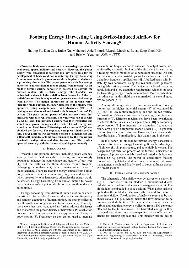
The schematic of the airflow energy harvester is shown in Fig. 1. It consists of an air bladder, a miniaturized ducted radial-flow air turbine and a power management circuit. The air bladder is embedded in shoe cushion. When a foot strike is applied on the air bladder, it converts the linear deformation of shoes into airflow. The direction of airflow is regulated by two check valves in Fig. 1, which makes the flow direction to be unidirectional all the time. The generated airflow actuates the turbine and electrical energy is collected from a DC generator attached to the turbine rotor. The harvested energy is then managed and stored in a supercapacitor by an off-the-shelf circuit for sensing applications. This bladder-turbine design
K. Cao and R. Martinez-Botas are with the Department of Electrical and Electronic Engineering, Imperial College London, London, SW7 2AZ, UK (e-mail: [email protected]).
R. Xu, M. A. Bhouri and S. G. Kim are with the Department of Mechanical Engineering, Massachusetts Institute of Technology, Boston, MA 02139, USA (e-mail: [email protected]).
Footstep Energy Harvesting Using Strike-Induced Airflow for Human Activity Sensing*
Hailing Fu, Kun Cao, Ruize Xu, Mohamed Aziz Bhouri, Ricardo Martinez-Botas, Sang-Gook Kim and Eric M. Yeatman, Fellow, IEEE
enables the generator to operate at a higher frequency than that of human motion, which improves the energy harvesting capability in a simple way. In order to achieve a high rotational frequency, namely the operating frequency of the generator, the airflow pressure inside the air bladder should be enhanced as much as possible. The cross-sectional area of the outlet is accordingly designed over 300 times smaller than that of the air bladder, which ensures that the air in the bladder has high pressure and high velocity when the airflow gets into the turbine.
The turbine is a critical component in this system. As the space in shoes is limited, the size of the turbine should be at millimeter scale to maintain unobtrusive. At small-scale, the driving torque provided by the passing airflow is limited, so the turbine is difficult to start up. Different types of air turbines are summarized in [13]. An enclosed radial-flow turbine, which is significantly different from large-scale wind turbines, is adopted in this paper. The enclosed turbine allows adaptation to the airflow duct and thus needs no orientation control to achieve output power. Such a turbine has been shown previously to be able to operate at very low pressure ratios and thus can harvest low grade flow energy [14]. A high conversion efficiency can be achieved when compared to competing turbines. Meanwhile, the radial-flow turbine provides a higher efficiency at low airflow speed than other types of turbines [15], which means higher torque leading to the turbine having better start-up at low airflow speed.
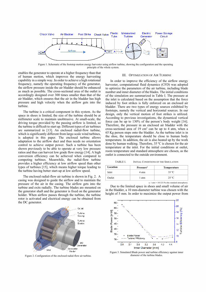
The enclosed radial-flow air turbine is shown in Fig. 2. A casing was designed to guide the airflow and to maintain the pressure of the air in the casing. The airflow gets into the turbine and exits radially. The turbine blades are mounted on the generator shaft and the generator is fixed on the generator holder. When airflow passes through the turbine, the turbine rotor is activated and electrical energy can be obtained from the DC generator.
III. OPTIMIZATION OF AIR TURBINE
In order to improve the efficiency of the airflow energy harvester, computational fluid dynamics (CFD) was adopted to optimize the parameters of the air turbine, including blade number and inner diameter of the blades. The initial conditions of the simulation are summarized in Table І. The pressure at the inlet is calculated based on the assumption that the force induced by foot strikes is fully enforced on an enclosed air bladder. There are two types of energy sources exhibited by footsteps, namely the vertical and horizontal sources. In our design, only the vertical motion of foot strikes is utilized. According to previous investigations, the dynamical vertical force can be up to 130% of the person’s body weight [16]. Therefore, the pressure in an enclosed air bladder with the cross-sectional area of 19 cm2 can be up to 4 atm, when a 65 Kg person steps onto the bladder. As the turbine inlet is in the shoe, the temperature should be close to human body temperature. In addition, the air is also heated up by the work done by human walking. Therefore, 35 ºC is chosen for the air temperature at the inlet. For the initial conditions at outlet, room temperature and standard atmosphere are chosen, as the outlet is connected to the outside environment.
TABLE I. INITIAL CONDITIONS OF THE SIMULATION
Location Pressurea Temperature
Inlet 4 atm 35 ºC
Outlet 1 atm 25 ºC
a. 1 atm = 101325 Pa (the standard atmosphere).
Due to the limited space in shoes and small volume of air in the bladder, a 10 mm-diameter turbine was chosen with the height of 5 mm. In order to maximize the output power from
Figure 2. Configuration of the enclosed radial-flow air turbine.
Figure 3. Simulated Blade power and turbine efficiency against inner
diameter of the turbine blades.
Figure 1. Schematic of the footstep motion energy harvester using airflow turbine, showing the configuration and the operating
principle of the whole system.
the harvester, the inner diameter of the turbine rotor was first simulated using CFD. The result is shown in Fig. 3. It indicates that the diameter has a significant influence to the efficiency of the whole system. With the decrease of the inner diameter, the output power and the efficiency are doubled with the diameter from Φ3.6 mm to Φ2.0 mm. Φ2.0 mm was chosen for the inner dimeter of the turbine rotor due to fabrication limits.
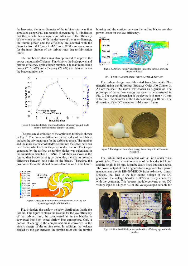
The number of blades was also optimized to improve the power output and efficiency. Fig. 4 shows the blade power and turbine efficiency against blade number. The maximum blade power (70.5 mW) and efficiency (22.4%) are obtained when the blade number is 9.
The pressure distribution of the optimized turbine is shown in Fig. 5. The pressure difference on two sides of each blade induces the driving torque for the turbine to rotate. The number and the inner diameter of blades determines the space between two blades, which affects the pressure distribution. The torque generated by the airflow on turbine blades was calculated in the simulation, which is 1.1 mNm. In addition, as shown in the figure, after blades passing by the outlet, there is no pressure difference between both sides of the blades. Therefore, the position of the outlet should be considered as well in the future.
Fig. 6 depicts the airflow velocity distribution inside the turbine. This figure explains the reasons for the low efficiency of the turbine. First, the compressed air in the bladder is converted into high speed airflow into atmosphere. Only a portion of energy in the compressed air is converted to the kinetic energy of the turbine rotor. In addition, the leakage caused by the gap between the turbine rotor and the turbine
housing and the vortices between the turbine blades are also power losses for the low efficiency.
IV. FABRICATION AND EXPERIMENTAL SET-UP
The turbine design was fabricated from Verowhite Plus material using the 3D printer Stratasys Objet 500 Connex 3. An off-the-shelf DC motor was chosen as a generator. The prototype of the airflow energy harvester is demonstrated in Fig. 7. The overall dimension of the device is 18 mm × 10 mm × 16 mm. The diameter of the turbine housing is 10 mm. The dimension of the DC generator is Φ4 mm× 10 mm.
The turbine inlet is connected with an air bladder via a plastic tube. The cross-sectional area of the bladder is 19 cm2 and the height is 16 mm. It can be easily fitted into shoe heels. The power output of the DC generator is regulated by a power management circuit EH4295/EH300 from Advanced Linear Devices, Inc. Due to the low output voltage of the DC generator, the voltage booster EH4295 is firstly connected with the generator. This booster module converts a low DC voltage input to a higher AC or DC voltage output suitable for
Figure 4. Simulated Blade power and turbine efficiency against blade number for blade inner diameter of 2 mm.
Figure 7. Prototype of the airflow energy harvesting with a £1 coin as
reference.
Figure 5. Pressure distribution of turbine blades, showing the operating principle of this turbine.
Figure 6. Airflow velocity distribution inside the turbine, showing the power losses.
Figure 8. Simulated Blade power and turbine efficiency against blade number.

many low-power energy harvesting applications. The power output of EH4295 is then stored in a capacitor with the capacitance of 1 mF in EH300. This modules can accept energy from many types of electrical energy sources and store this energy to power conventional 3.3V and 5.0V electrical devices. The energy stored in the capacitor is finally used to power a tiny Bluetooth fitness tracker in the smart sneakers Li Ning Smart. The whole system is shown in Fig. 8. The fitness tracker was originally powered by a button cell. During the experiment, the battery was removed and the tracker was fully powered by the power output of EH300.
V. RESULTS AND DISCUSSION
The power generating capability of the airflow energy harvester was first examined without connecting with the power management circuit. The output of the DC generator was directly connected with a resistor as a load. The peak output voltage and peak output power were measured for difference load resistance. The results are shown in Fig. 9. A 90.6 mW peak output power was obtained with the optimal load resistance of 30.4 Ω.
Then the harvester was tested with the power management circuit. The output voltage of the circuits EH300 and EH4295 is illustrated in Fig. 9. In this test, the air bladder was pushed by footsteps from a 65 Kg person. Around 165 steps was stroked on the bladder before the voltage of EH300 reached its peak value (5.44 V). As shown in Fig. 9, the output voltage from EH4295 is in a discontinuous AC form and the output voltage from EH300 increases steadily before arriving at the maximum value.
The amount of energy collected during the whole process can be calculated using the following equation.
1 10 5.44 14.8mJ, (1)
where C is the capacitance of the capacitor and V is the voltage of the capacitor. Therefore, the amount of energy per footstep is 89.7 µJ. If the frequency of human motion is 2 Hz, the output power of the whole system is 179.4 µW. The low output power of the power management circuit is mainly caused by the mismatching of the DC generator and the voltage booster. The output power can be enhanced by increasing the volume of the air bladder.
The performance of the fitness tracker was then tested with the airflow energy harvester as power supply. During the test, the battery for the tracker was removed, and the device was fully powered by the energy collected from foot strikes. Two air bladders were installed to improve the energy harvesting capability of the system. The output voltage of EH300 during the operation of the tracker is shown in Fig. 11. When the
Bluetooth module is disconnected, the generated power is high enough to power the sensing unit in the tracker and the output voltage of EH300 is at its maximum value.
The Bluetooth module is the most power consuming part in the tracker. During the period of Bluetooth configuration and data transmission, the output voltage of EH300 decreases from 5V to about 3.2 V, but after that the power generated by the harvester is good enough to maintain the voltage even if Bluetooth is still connected. When Bluetooth is shut-down, the output voltage increases to its peak value.
The power consumption per Bluetooth configuration and data transmission can be calculated using Eq. (1). The energy consumed during this process is 7.38 mJ. Fig. 12 shows the process of Bluetooth configuration and data transmission in a cellphone application (Mi Fit). At beginning, the Bluetooth module is disconnected. When the switch for Bluetooth in the cellphone is turned on, the configuration process starts. This process consumes a large portion of energy compared with the operation of sensing units in the tracker. After configuration, the data on the tracker is transmitted to the cellphone. The data shows the total steps for one day and the calorie consumed by
Figure 10. Output voltage of EH300 and EH4295.
Figure 11. Output voltage of EH300, showing the power
consumption of the fitness tracker and the capability of the footstep energy harvester as power supply.
Figure 9. Peak output voltage and peak output power of the DC
generator for different load resistance.
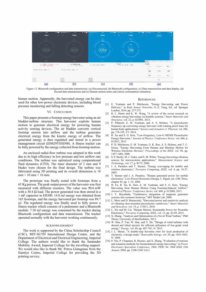
human motion. Apparently, the harvested energy can be also used for other low-power electronic devices, including blood pressure monitoring and falling detecting sensors.
VI. CONCLUSION
This paper presents a footstep energy harvester using an air bladder-turbine structure. This harvester exploits human motion to generate electrical energy for powering human activity sensing devices. The air bladder converts vertical footstep motion into airflow and the turbine generates electrical energy from the kinetic energy of airflow. The generated energy is then regulated and stored in a power management circuit (EH4295/EH300). A fitness tracker can be fully powered by the energy collected from footstep motion.
An enclosed radial-flow turbine was adopted in this work due to its high efficiency in low pressure and low airflow rate conditions. The turbine was optimized using computational fluid dynamics (CFD). The inner diameter of 2 mm and 9 blades were chosen for the final design. The turbine was fabricated using 3D printing and its overall dimension is 18 mm × 10 mm × 16 mm.
The prototype was finally tested with footsteps from a 65 Kg person. The peak output power of the harvester was first measured with different resistors. The value was 90.6 mW with a 30.4 Ω load. The power generated was then stored in a 1 mF capacitor in EH300. 14.8 mJ energy was obtained from 165 footsteps, and the energy harvested per footstep was 89.7 µJ. The regulated energy was finally used to fully power a fitness tracker which consists of a pedometer and a Bluetooth module. 7.38 mJ energy was consumed by the tracker during Bluetooth configuration and data transmission. The tracker operated normally with the harvester working continuously.
ACKNOWLEDGMENT
The work is supported by the China Scholarship Council (CSC), MIT-SUTD International Design Center, and the Department of Electrical and Electrical Engineering, Imperial College. The authors would like to thank the Santander Mobility Award, Imperial College for the travelling support. We would also like to thank Mr. Petros Giataganas from the Hamlyn Centre, Imperial College for providing the 3D printing service.
REFERENCES [1] E. Yeatman and P. Mitcheson, "Energy Harvesting and Power
Delivery," in Body Sensor Networks, G.-Z. Yang, Ed., ed: Springer London, 2014, pp. 237-272.
[2] R. L. Harne and K. W. Wang, "A review of the recent research on vibration energy harvesting via bistable systems," Smart Materials and Structures, vol. 22, p. 023001, 2013.
[3] P. Pillatsch, E. M. Yeatman, and A. S. Holmes, "A piezoelectric frequency up-converting energy harvester with rotating proof mass for human body applications," Sensors and Actuators A: Physical, vol. 206, pp. 178-185, 2/1/ 2014.
[4] R. Xu and S. G. Kim, "Low-Frequency, Low-G MEMS Piezoelectric Energy Harvester," Journal of Physics: Conference Series, vol. 660, p. 012013, 2015.
[5] P. D. Mitcheson, E. M. Yeatman, G. K. Rao, A. S. Holmes, and T. C. Green, "Energy Harvesting From Human and Machine Motion for Wireless Electronic Devices," Proceedings of the IEEE, vol. 96, pp. 1457-1486, 2008.
[6] S. P. Beeby, M. J. Tudor, and N. M. White, "Energy harvesting vibration sources for microsystems applications," Measurement Science and Technology, vol. 17, p. R175, 2006.
[7] J. A. Paradiso and T. Starner, "Energy scavenging for mobile and wireless electronics," Pervasive Computing, IEEE, vol. 4, pp. 18-27, 2005.
[8] T. Starner and J. A. Paradiso, "Human generated power for mobile electronics," Low-Power Electronics Design, C. Piguet, ed., CRC Press, chapter 45, pp. 1–35, 2004.
[9] H. Fu, R. Xu, K. Seto, E. M. Yeatman, and S. G. Kim, "Energy Harvesting from Human Motion Using Footstep-Induced Airflow," Journal of Physics: Conference Series, vol. 660, p. 012060, 2015.
[10] J. Y. Hayashida, "Unobtrusive integration of magnetic generator systems into common footwear," MIT Media Lab, 2000.
[11] L. Moro and D. Benasciutti, "Harvested power and sensitivity analysis of vibrating shoe-mounted piezoelectric cantilevers," Smart Materials and Structures, vol. 19, p. 115011, 2010.
[12] L. Xie and M. Cai, "Human Motion: Sustainable Power for Wearable Electronics," Pervasive Computing, IEEE, vol. 13, pp. 42-49, 2014.
[13] X. Zhang, "Analysis and Optimisation of a Novel Wind Turbine," PhD Thesis, University of Hertfordshire, 2013.
[14] W. Han, P. Yan, W. Han, and Y. He, "Design of wind turbines with shroud and lobed ejectors for efficient utilization of low-grade wind energy," Energy, vol. 89, pp. 687-701, 9// 2015.
[15] J. L. Menet, "A double-step Savonius rotor for local production of electricity: a design study," Renewable Energy, vol. 29, pp. 1843-1862, 9// 2004.
[16] P. Niu, P. Chapman, R. Riemer, and X. Zhang, "Evaluation of motions and actuation methods for biomechanical energy harvesting," in Power Electronics Specialists Conference, 2004. PESC 04. 2004 IEEE 35th Annual, 2004, pp. 2100-2106 Vol.3.
Figure 12. Bluetooth configuration and data transmission: (a) Disconnected, (b) Bluetooth configuration, (c) Data transmission and data display, (d)
Second data transmission and (e) Human motion notes and calorie consumption estimation.