fms introduction and description -...
TRANSCRIPT
FMS Introduction and Description 1
1
FMS Introduction and Description
1.1 INTRODUCTION
In the middle of 1960s, market competition became more intense. During 1960 to 1970 cost was theprimary concern. Later quality became the priority. As the market became more and more complex,speed of delivery became something customer also needed.
A new strategy was formulated (Customizability). The companies have to adapt to theenvironment in which they operate, to be more flexible in their operations and to satisfy differentmarket segments. Thus the innovation of FMS became related to the effort of gaining competitiveadvantage.
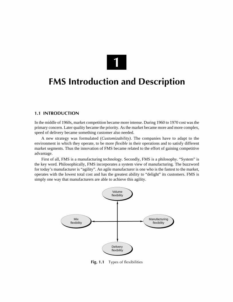
First of all, FMS is a manufacturing technology. Secondly, FMS is a philosophy. “System” isthe key word. Philosophically, FMS incorporates a system view of manufacturing. The buzzwordfor today’s manufacturer is “agility”. An agile manufacturer is one who is the fastest to the market,operates with the lowest total cost and has the greatest ability to “delight” its customers. FMS issimply one way that manufacturers are able to achieve this agility.
Fig. 1.1 Types of flexibilities
Deliveryflexibility
Volumeflexibility
Mixflexibility
Manufacturingflexibility

2 Flexible Manufacturing System
1.2 DEFINITION
A flexible manufacturing system (FMS) is an arrangement of machines ... interconnected by atransport system. The transporter carries work to the machines on pallets or other interface units sothat work-machine registration is accurate, rapid and automatic. A central computer controls bothmachines and transport system.
Or“FMS consists of a group of processing work stations interconnected by means of an automated
material handling and storage system and controlled by integrated computer control system.”FMS is called flexible due to the reason that it is capable of processing a variety of different part
styles simultaneously at the workstation and quantities of production can be adjusted in response tochanging demand patterns.
1.3 BASIC COMPONENTS OF FMS
The basic components of FMS are:
1. Workstations
2. Automated Material Handling and Storage system.3. Computer Control System
1. Workstations: In present day application these workstations are typically computer numericalcontrol (CNC) machine tools that perform machining operation on families of parts. Flexiblemanufacturing systems are being designed with other type of processing equipments includinginspection stations, assembly works and sheet metal presses. The various workstations are
(i) Machining centers(ii ) Load and unload stations
(iii ) Assembly work stations(iv) Inspection stations(v) Forging stations
(vi) Sheet metal processing, etc.
2. Automated Material Handling and Storage system:The various automated material handlingsystems are used to transport work parts and subassembly parts between the processing stations,sometimes incorporating storage into function.
The various functions of automated material handling and storage system are
(i) Random and independent movement of work parts between workstations
(ii ) Handling of a variety of work part configurations(iii ) Temporary storage(iv) Convenient access for loading and unloading of work parts
(v) Compatible with computer control

FMS Introduction and Description 3
3. Computer Control System: It is used to coordinate the activities of the processing stations andthe material handling system in the FMS. The various functions of computer control system are:
(i) Control of each work station(ii ) Distribution of control instruction to work station
(iii ) Production control
(vi) Traffic control(v) Shuttle control
(vi) Work handling system and monitoring
(vii) System performance monitoring and reportingThe FMS is most suited for the mid variety, mid value production range.
Fig. 1.2 Application characteristics of FMS
Fig. 1.3 Flexible manufacturing system
Low
Low
Medium
High
Medium
Production Volume
High
ProductVariety
Stand alone NCmachines
FlexibleManufacturingsystems
Transferlines
CNC 1
Toolchanger
Toolchanger
Toolchanger
IndexingtablesCNC 2
CNC 3
As/RS
Out In Out In
Out In
Com
pute
rco
ntro
l
Raw material storage(roller conveyor)
Load/unload stations
Temporary storage areas(33 pallet spaces)R
awm
ater
ials
tora
ge(f
loor
spac
e)
L/U L/U
AG
V1
AGV 2

4 Flexible Manufacturing System
1.4 THE SIGNIFICANCE OF FMS IN THE 1990s
The installed worldwide FMS base in 1989 was estimated to be around 500 to 1200 systems, thehigher figure arising when a system is defined as having 2 or more CNC machine tools connectedby a materials handling system, and controlled by a central computer. Ranta and Tchijov suggestthat this number will rise to around 2500–3500 by the year 2000. This led them to suggest that “thestrategic majority of production of the metal-working industries in the industrialized countries willbe produced by FMS or similar systems [by the year 2000].”
Kelley’s empirical research in 1987 strongly contradicts this. In a large (>1000 firms) survey ofUS metal working firms, she found that less than 5 per cent of those plants with computerizedautomation have an FMS and that FMS constituted only 1.5 per cent of the total number of installationsof computerized automation. Why are there still so few FMS in the world given that small-batchengineering production is a significant proportion of manufacturing output?
There are significant practical reasons for the disparity between the promise of FMS in the1980s and its narrowness and scarcity of application in the early 1990s. These reasons are outlinedbelow separately, though they are very much interdependent. Different approaches to flexibilityand their meanings are shown Table 1.1.
Table 1.1 Different approaches to flexibility and their meanings
Approach Flexibility meaning
1. Manufacturing n The capability of producing different parts without major retoolingn A measure of how fast the company converts its process from
making an old line of products to produce a new productn The ability to change a production schedule, to modify a part, or to
handle multiple parts2. Operational n The ability to efficiently produce highly customized and unique products
3. Customer n The ability to exploit various dimension of speed of delivery4. Strategic n The ability of a company to offer a wide variety of products to its
customers5. Capacity n The ability to rapidly increase or decrease production levels or to shift
capacity quickly from one product or service to another
So, what is flexibility in manufacturing?There are three levels of manufacturing flexibility.
(a) Basic flexibilities
n Machine flexibility: The ease with which a machine can process various operationsn Material handling flexibility: A measure of the ease with which different part types can be
transported and properly positioned at the various machine tools in a systemn Operation flexibility: A measure of the ease with which alternative operation sequences
can be used for processing a part type

FMS Introduction and Description 5
(b) System flexibilities
n Volume flexibility: A measure of a system’s capability to be operated profitably at differentvolumes of the existing part types
n Expansion flexibility: The ability to build a system and expand it incrementallyn Routing flexibility: A measure of the alternative paths that a part can effectively follow
through a system for a given process plann Process flexibility: A measure of the volume of the set of part types that a system can
produce without incurring any setup
n Product flexibility: The volume of the set of part types that can be manufactured in a systemwith minor setup
(c) Aggregate flexibilities
n Program flexibility: The ability of a system to run for reasonably long periods withoutexternal intervention
n Production flexibility: Tthe volume of the set of part types that a system can produce withoutmajor investment in capital equipment
n Market flexibility: The ability of a system to efficiently adapt to changing market conditions
1.5 DIFFERENT TYPES OF FMS
The different types of FMS are
n Sequential FMS
n Random FMSn Dedicated FMSn Engineered FMS
n Modular FMS
Sequential FMS: It manufactures one-piece part batch type and then planning and preparation iscarried out for the next piece part batch type to be manufactured. It operates like a small batchflexible transfer line.
Random FMS: It manufactures any random mix of piece part types at any one time.
Dedicated FMS: It continually manufactures, for extended periods, the same but limited mix ofpiece part batch types.
Engineered FMS: It manufactures the same mix of part types throughout its lifetime.
Modular FMS: A modular FMS, with a sophisticated FMS host, enables and FMS user to expandtheir FMS capabilities in a stepwise fashion into any of the previous four types of FMS.
1.6 TYPES OF FMS LAYOUTS
The different types of FMS layouts are:

6 Flexible Manufacturing System
1. Progressive or Line Type2. Loop Type3. Ladder Type
4. Open field type5. Robot centered type
1. Progressive or Line type:The machines and handling system are arranged in a line as shown inthe Fig.1.4 (a). It is most appropriate for a system in which the part progress from one workstationto the next in a well defined sequence with no back flow. The operation of this type of system isvery similar to transfer type. Work always flows in unidirectional path as shown in Fig.1.4 (a).
2. Loop Type: The basic loop configuration is as shown in Fig. 1.4 (b). The parts usually move inone direction around the loop, with the capability to stop and be transferred to any station. Theloading and unloading station are typically located at one end of the loop Fig.1.4 (b)
3. Ladder Type: The configuration is as shown in Fig. 1.4 (c). The loading and unloading stationis typically located at the same end. The sequence to the operation/transfer of parts from one machinetool to another is in the form of ladder steps as shown in Fig.1.4 (c)
Fig. 1.4
Unloadstation
UnloadstationPaller
Load/unloadstations
Paller
Machinetool
Load/unloadstation
(a) Progressive FMS (b) Closed-loop FMS
(c) FMS ladder layour

FMS Introduction and Description 7
(d) Open field FMS
(e) Robot centered FMS
Fig. 1.4 (Contd.)
Finished-partconveyor
Minicomputer
Micro-processor
CNC grinder Mic
ropr
oc
Robot
CNCturningcenter
Mic
ro-
proc
esso
r
CNCmalingcenter
Tool changerMicroprocessorcomputer
Row
-par
tco
nvey
or
Toolchargers
CNC machines
Automaticwork
changer
AGV
Coordinatemeasuringmachine
Car
tmai
nten
ance
Par
twas
hst
atio
n
Chip collection
Load/unloadstations
Tooldeliverschains
Control center/computer room
Conferenceroom
Fixturebuild-upstation

8 Flexible Manufacturing System
4. Open Field Type: The configuration of the open field is as shown in Fig.1.4 (d). The loadingand unloading station is typically located at the same end. The parts will go through all the substations,such as CNC machines, coordinate measuring machines and wash station by the help of AGV’sfrom one substation to another.
5. Robot Centered Type:Robot centered cell is a relatively new form of flexible system in whichone or more robots are used as the material handling systems as shown in Fig.1.4 (e). Industrialrobots can be equipped with grippers that make them well suited for handling of rotational parts.
1.6.1 Factors Influencing the FMS Layouts
The various factors influencing the layouts of FMS are:
n Availability of raw materialn Proximity to market
n Transport facilitiesn Availability of efficient and cheap laborn Availability of power, water and fuel
n Atmospheric and climatic conditionn Social and recreation facilitiesn Business and economic conditions
1.6.2 Seeking Benefits on Flexibility
Today’s manufacturing strategy is to seek benefits from flexibility. This is only feasible when aproduction system is under complete control of FMS technology. Having in mind the Process-Product Matrix you may realize that for an industry it is possible to reach for high flexibility bymaking innovative technical and organizational efforts. See the Volvo’s process structure that makescars on movable pallets, rather than an assembly line. The process gains in flexibility. Also, theVolvo system has more flexibility because it uses multi-skill operators who are not paced by amechanical line. So we may search for benefits from flexibility on moving to the job shop structures.
Actually, the need is for flexible processes to permit rapid low cost switching from one productline to another. This is possible with flexible workers whose multiple skills would develop theability to switch easily from one kind of task to another.
As main resources, flexible processes and flexible workers would create flexible plants as plantswhich can adapt to changes in real time, using movable equipment, knockdown walls and easilyaccessible and re-routable utilities.
1.7 FMS�AN EXAMPLE OF TECHNOLOGY AND AN ALTERNATIVE LAYOUT
The idea of an FMS was proposed in England (1960s) under the name “System 24”, a flexiblemachining system that could operate without human operators 24 hours a day under computercontrol. From the beginning the emphasis was on automation rather than the “reorganization ofworkflow”.
Early flexible manufacturing systems were large and very complex, consisting of dozens ofComputer Numerical Controlled machines (CNC) and sophisticated material handling systems.
FMS Introduction and Description 9
They were much automated, very expensive and controlled by incredibly complex software. Therewere only a limited number of industries that could afford investing in a traditional FMS asdescribed above.
Currently, the trend in FMS is toward small versions of the traditional FMS, called flexiblemanufacturing cells (FMC). Today two or more CNC machines are considered as a flexible cell andtwo ore more cells are considered a flexible manufacturing system.
Thus, a Flexible Manufacturing System (FMS) consists of several machine tools along withpart and tool handling devices such as robots, arranged so that it can handle any family of parts forwhich it has been designed and developed.
1.8 OBJECTIVES OF AN FMS
A study, carried out with West Germany manufacturing has shown the major aims of installing anFMS to be:
n Decreased Lead Timesn Increased Through putn Increased machine utilization
n Improved Due Date Reliabilityn Decreased Store Inventors Levelsn Decreased Work in Progressn Increased Quality
1.9 AIMS OF FMS
n To reduce costsn Better utilization of the production equipment reduction of stocks (ex: Work in progress—
capital shorter through put times)
n Reduction of piece part unit costs.n To increase Technical Performance:
l Increased production levels
l Greater product mixturel Simultaneous product mixture manufacturingl Integration of the production system into the factory’s logistical system
l Smaller batch sizesl Shorter or zero change over or reset of times
n To improve Order Development:
l Shorter lead times/delivery timesl Determination of production capacities
n To assist future Corporate Security:
l Increased Competitivenessl Increased Qualityl Improved Company Image

10 Flexible Manufacturing System
1.10 THE PRINCIPLE OBJECTIVES OF FMS
The principle objectives of FMS are
1. To improve operational control through:n Reduction in the number of uncontrollable variables.n Providing tools to recognize and react quickly to deviations in the manufacturing plann Reducing the dependence of human communication.
2. To reduce direct labor:n Removing operators from the machining site (their responsibilities activities can be
broadened).n Eliminating dependence on highly skilled machines (their manufacturing skills can be better
utilized in manufacturing engineering functions).
n Providing a catalyst to introduce and support unattended or lightly attended machining operation.
3. To improve short run responsiveness consisting of:n Engineering changesn Processing changes
n Machining downtime or unavailabilityn Cutting tool failuren Late material delivery
4. To improve long-run accommodations through quicker and easier assimilation of:n Changing product volumesn New product additions and introductionsn Differentiation part mixes
n Increase Machine Utilization by:l Eliminating machine setupl Utilizing automated features to replace manual intervention
l Providing quick transfer devices to keep machines in the cutting cyclen Reduce inventors by:
l Reducing lot sizes
l Improving inventors turn-overl Providing the planning tools for JIT manufacturing
1.11 ADVANTAGES AND DISADVANTAGES OF FMS IMPLEMENTATION
The various advantages and disadvantages of FMS implementation are
1.11.1 Advantages
n Faster, lower-cost changes from one part to another which will improve capital utilizationn Lower direct labor cost, due to the reduction in number of workers

FMS Introduction and Description 11
n Reduced inventory, due to the planning and programming precisionn Consistent and better quality, due to the automated controln Lower cost/unit of output, due to the greater productivity using the same number of workers
n Savings from the indirect labor, from reduced errors, rework, repairs and rejects
1.11.2 Disadvantages
n Limited ability to adapt to changes in product or product mix (ex. machines are of limitedcapacity and the tooling necessary for products, even of the same family, is not alwaysfeasible in a given FMS)
n Substantial pre-planning activityn Expensive, costing millions of dollarsn Technological problems of exact component positioning and precise timing necessary to
process a component
n Sophisticated manufacturing systems
1.12 AREA OF APPLICATION OF A FMS IN INDUSTRY
The following chart in the Fig. 1.5 shows the various applications in an industry.
Fig. 1.5 Area of applications of FMS in an industry
Terti ary In dustry
Service Process Manufacturing
Banking,retail,transportetc.
Chemicals,foods, etc.
Jobs Batch
Small Large
Production
Planning Technicalservices
CADCAQCAT
Financialcapacityproduction
Series
Flexibletransfer line
Transfer line,rotary, linear

12 Flexible Manufacturing System
1.13 VARIOUS EQUIPMENTS AND THEIRFUNCTIONS REQUIRED FOR AN FMS
The two important equipments of FMS are:
1. Primary equipment: It adds value to the piece parts being manufactured. It consists ofwork centers, which physically machine a piece part, and process centers, which assemble,check or wash, etc. the piece parts.
2. Secondary equipment: It is used to support the primary equipment in achieving this goal.It consists of support stations such as pallet/fixture load-unload stations and toolcommissioning/setting area, etc. It also consists of support equipments such as robots,pallet/fixture/stillage stores, pallet buffer stations, tool stores, raw material stores, transportsystem (AGVs, RGVs, robots) for tooling and piece parts, etc.
1.14 INNOVATIONS THAT HAVE ADVANCEDTHE MANUFACTURING INDUSTRIES
Fig. 1.6 Innovations that have advanced the manufacturing industries
Cottage Industries
Centralized industry Mechanization
Processed IndustriesProcessed Industries Automation
Stand alone automatedCNC machines/ robots/computer
Networks
Transistors,Integrated circuits,Digital computers,Microcoputers.
Cellularproduction
2000’s
Integrated workshops
Factory of Future (FOF)Concept
ManufacturingIndustries
1700’s
1800’s
1900’s

FMS Introduction and Description 13
1.15 CIM TECHNOLOGY
Fig. 1.7 CIM Technology
CAPP Computer Aided Process Planning FMS Flexible Manufacturing SystemCAP Computer Aided Planning FMC Flexible Manufacturing Cell
CAQ Computer Aided Quality Control FAS Flexible Manufacturing AssemblyCAD Computer Aided Design DNC Direct Numerical ControlCADD Computer Aided Design and Drafting DAS Data Acquisition System
MRP Materials Resource Planning PDA Production DataCIM Computer Integrated Manufacturing AC Area ControlCC Cell Control
1.16 HIERARCHY OF CIM
The computer integrated manufacturing includes all of the engineering functions of CAD/CAMalong with firm’s business functions that are related to manufacturing.
Factory of the Future (FOF)
CIM
Operational
CAE
CAPPCAPCAQCADCADDMRP
CAE
Organizational
Corporate serviceFinance
Business Planning
Marketing FMS FMC
DNCDAS
PDAMDA
ACCC
FAS
Hand Book

14 Flexible Manufacturing System
The activities in factory’s environment can be logically distributed into a hierarchy to run on adata exchange network system.
There are 5 levels of control or organization as shown Fig. 1.8.
Fig. 1.8 CIM hierarchy
Control functions are executed at Level 1 and 2 of the CIM hierarchy consisting of CNC, NC,RC and PLC equipments.
Levels 3, 4 and 5 define the organizational levels such as FMS host, area controller, plantcontrol or MRP computer, etc.
Level 1 of the hierarchy include the drives, motors, limit switches, etc. of the productionequipment.
Plant ControlCentralise databaseProduction planning
è
È
Plant ControlCentralise databaseProduction planning
è
È
Long TermYearsMonths
è
è
Long TermYearsMonths
è
è
Short termWeeksDays
è
è
Short termWeeksDays
è
è
Event DrivenHoursMinutes
è
è
Event DrivenHoursMinutes
è
è
Real TimeSecondsMilliseconds
è
è
Real TimeSecondsMilliseconds
è
è
Area controller (MISMRP, CAP CAD SFDC)
Localised databaseArea planning
è
è
Cell controller (DNC, MasterFMS, FMS, Hosts)
Manufacturing controlMaterial flow controlCurrent period database
è
è
è
Process ControllersOperational dataFeedback controlè
è
Relays ActuatorsSwitches ValvesDrives
MainframesMinis
Hardware Function D ata Usage
Minis
MinisWsPC
CNCPLCRC

FMS Introduction and Description 15
Level 2 includes the controllers, which enable a machine to achieve an autonomous standalonecapability. The CNCs, PLCs and microcomputers enable the machine to which they are dedicatedto run unsupported from controllers on other hierarchy levels.
A production cell host computer can be installed above the stand-alone machine to provideorganization and monitoring of a group of such machines. This is the level 3(a) where usuallypersonal computers and minicomputers are installed. It is often dependent upon the size of thesystem and complexity, whether the manufacturing industries define these systems as
3. Flexible manufacturing system (FMS)—Large systems4. Flexible manufacturing cells (FMC)—Small systems
Level 3(b) is the one where the host computer is often known as a coordination or master host.Level 4 configures the control level for an area within a factory. The input and output of material
into the area is planned at this level. The planning for a particular area involves an interactivedialogue between the computer on this level and say FMS host, the computer is termed as an areacontroller. If not and the planning is carried out without any feedback, the computer at this level isopen loop shop floor scheduling system.
If no planning is carried out by the computer, but only the collection and evaluation of datafrom level 3, the computer is classed as a management information system. The minicomputers andmainframes of level 5 provide the automation of the factory wide or corporate functions. Suchfunctions include CAP, CAD, MRP, finance, marketing, etc.
1.17 DIRECT REAL TIME SCHEDULE CONTROL
The major functions of an FMS host are illustrated in the Fig. 1.9Planned work is only allocated to a specific machine when the individual piecepart has been
setup in a fixture on a pallet and a machine is available, with all its necessary equipment andprograms, to process it. The object of the host is to keep the expensive capital equipment utilized bysupplying with it with work. This is best achieved when preparatory work is carried out simultaneouslywhilst the machine is still working. The host organizes the preparation and transportation of thework so that it is readily available to the machine when it next requests some work. The bestmachine utilization can be obtained when a machine’s layout includes an internal machine buffer.The host can then organize this internal buffer to be always loaded with work. If this buffer isalways loaded with work there will always be work available for the machine to transfer immediatelyinto the spindle’s work area. Piece parts are moved from a machine under the organization of thehost to other machines, or to a system buffer station, if the next machine in a piecepart’s processroute is busy and cannot accept a piecepart into its buffer.

16 Flexible Manufacturing System
Fig. 1.9 The major functions of FMS host
1.18 FMS CONCEPTS
To get clear information with application of FMS the concepts concerned to FMS must be understood.The concepts cover mixes, machine allocations, flows, planning and scheduling.
System mixes:
(a) Piece part mix: The distinction must be made between:n total piece part mixn planned piece part mixn ‘live’ order mix
n ‘live’ piece parts
Transport System
Wash m/cM/c toolM/c toolLoad/
UnloadStations
ToolSettingStation
CONTROL DATA DYNAMIC DATA
—Layout—Transport—Process Plans—Tool Data—Worlds Calendar
—Transport Units—Production Orders
Hos
Data base—Master date—Open date
Capacity Planning
Setup dialog
Operator dialog
Tool Setting
Material flow
INTER AL S/W BUS
DRIVERS & HANDLERS
COUPLED PROGRAMS (ON-LINES)
Reports
Order Admin
Tool exchange M/c Control DNC Tool Admin Simulator
TransportHandling
Decoupled Programs (off. Line)
System Operating
Systeminuge
Shifts Lists
Statistic
System listing
Synchronisation

FMS Introduction and Description 17
The total piece part mix is that mix, which over the months and years, FMS has the manufacturingcapability.
The host of FMS can organize the manufacture of a wide range of various piece parts within thegiven primary equipments manufacturing capabilities.
The machines have a finite capacity for any particular period in which production is to befollowed or planned.
A subset of the total live piece part mix is manufactured simultaneously in the system. As thepiece parts drop out of the system more piece parts of the planned live mix can enter the system atthe load and unload stations, thus the FMS is constantly fed with new work.
(b) Piece part mix types: The piece parts can classified asn Prismatic (cuboid shaped components—for drilling, milling, reaming, etc.)n Rotational (round cylindrical components)—or turning, grinding, etc.
n Hybrid (rotational and prismatic shaped components) ex-crank shaft
(c) Machine allocation mix: An operation on a piecepart needs a NC program loaded into a machinetool’s controller for the machine to execute the operation. When an FMS operation is considered,then as a single NC program which itself has several operations, each one better known as a cuttingoperation.
The allocation of work centers to machine the different operations of a piece part is defined aseither interchangeable allocation or complementary allocation as shown in the Fig. 1.10.
Fig. 1.10 Process routings in an FMS
NC program 1 NC program 2
Operation 0001
Operation 0001
NC program 1
NC program 2
NC program 3
Operation 0002
Operation 0003NC program 3
Machine1 Machine2 Machine3
Machine1
Machine2
Machine3
Interchangeablemachine group
Complementarymachine group