fmj lg cf - fmj storage · fmj lg cf fmj storage 14241 ne wood/duval rd suite 388
TRANSCRIPT
FMJ LG CF
FMJ Storage 14241 NE Wood/Duval Rd www.fmjstorage.com Suite 388
(206) 605-1394 Woodinville, WA 98077
OVERVIEW
The FMJ Last Generation CF is a small, low cost, high performance, removable solid-state memory storage subsystem. It is an appropriate replacement for first generation Compact Flash cards and host systems that require low power, small scalable storage solutions, and compatibility with earlier PIO based hard drives. FMJ technology is designed for customer’s that prefer reliable operation in harsh environments and a long product lifecycle. Every FMJ LG CF is integrated with technology that prevents data corruption and loss from power disturbances and Self-Monitoring Analysis and Reporting Technology (SMART). Amongst the endless number of applications are networking products, military systems, interactive kiosks, record and playback systems, medical equipment, industrial control systems, avionics, and voting machines.
FEATURES
• Capacity range: 128MB to 8GB • Industry standard Type I CF form
factor
• Integrated wear-leveling and ECC technology
• Supports both 8-bit and 16-bit
data register transfers
• Supports dual-voltage 3.3V or 5V interface
• MTBF >4,000,000 hours
• CompactFlash 2.0 compatible
• ATA-5 compliant
• Supports PIO modes 0-4, multi-
word DMA 0-2
• RoHS 6 of 6 compliant • Industrial temperature version
available
FMJ LG CF
FMJ Storage 14241 NE Wood/Duval Rd www.fmjstorage.com Suite 388
(206) 605-1394 Woodinville, WA 98077
Table of Contents 1.0 Physical Specifications ......................................................... 3
1.1 Physical Dimensions............................................................................................... 3
2.0 Product Specifications ......................................................... 4
2.1 System Performance .............................................................................................. 4
2.2 Reliability ............................................................................................................... 4
2.3 Capacity ................................................................................................................. 4
2.4 Environmental ....................................................................................................... 5
3.0 Electrical Specifications ....................................................... 5
3.1 Absolute Maximum Ratings ................................................................................... 5
3.2 DC Specifications ................................................................................................... 5
3.2 Pin Assignments/Signals ........................................................................................ 6
3.3 Signal Timing ......................................................................................................... 6
4.0 CF Specifications ................................................................. 7
4.1 Card Information Structure (CIS) ............................................................................ 7
4.2 ATA Commands Supported .................................................................................... 8
4.2.1 ATA Set Feature Sub-Commands Supported ....................................................... 9
4.3 Identify Device Information ................................................................................. 10
5.0 Ordering Information ........................................................ 13
FMJ LG CF
FMJ Storage 14241 NE Wood/Duval Rd www.fmjstorage.com Suite 388
(206) 605-1394 Woodinville, WA 98077
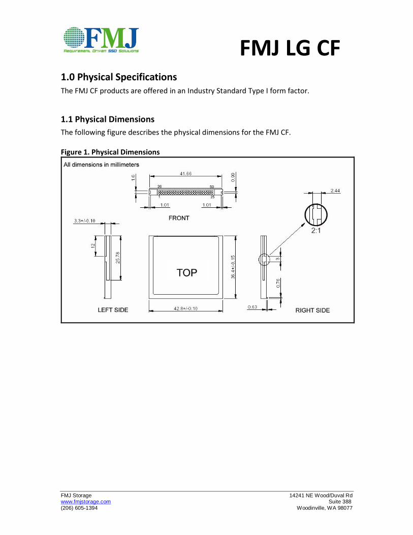
1.0 Physical Specifications
The FMJ CF products are offered in an Industry Standard Type I form factor.
1.1 Physical Dimensions
The following figure describes the physical dimensions for the FMJ CF. Figure 1. Physical Dimensions
FMJ LG CF
FMJ Storage 14241 NE Wood/Duval Rd www.fmjstorage.com Suite 388
(206) 605-1394 Woodinville, WA 98077
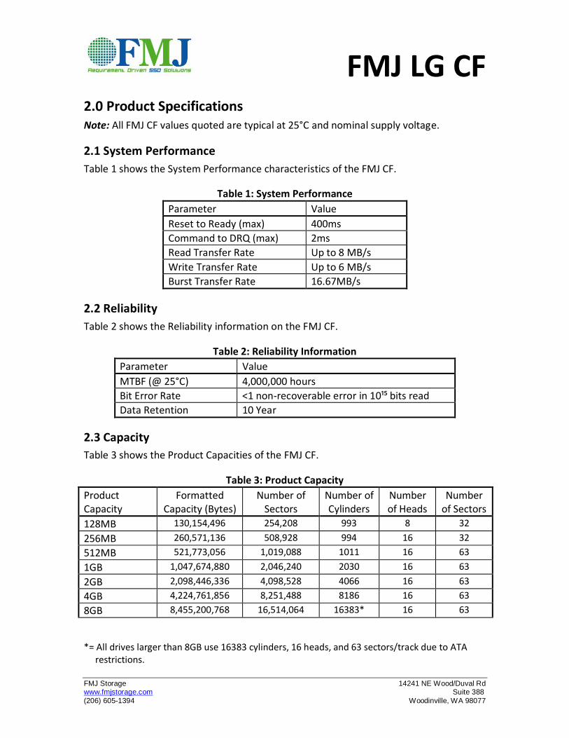
2.0 Product Specifications
Note: All FMJ CF values quoted are typical at 25°C and nominal supply voltage.
2.1 System Performance
Table 1 shows the System Performance characteristics of the FMJ CF.
Table 1: System Performance
Parameter Value
Reset to Ready (max) 400ms
Command to DRQ (max) 2ms
Read Transfer Rate Up to 8 MB/s
Write Transfer Rate Up to 6 MB/s
Burst Transfer Rate 16.67MB/s
2.2 Reliability
Table 2 shows the Reliability information on the FMJ CF.
Table 2: Reliability Information
Parameter Value
MTBF (@ 25°C) 4,000,000 hours
Bit Error Rate <1 non-recoverable error in 10¹⁵ bits read
Data Retention 10 Year
2.3 Capacity
Table 3 shows the Product Capacities of the FMJ CF.
Table 3: Product Capacity
Product Capacity
Formatted Capacity (Bytes)
Number of Sectors
Number of Cylinders
Number of Heads
Number of Sectors
128MB 130,154,496 254,208 993 8 32
256MB 260,571,136 508,928 994 16 32
512MB 521,773,056 1,019,088 1011 16 63
1GB 1,047,674,880 2,046,240 2030 16 63
2GB 2,098,446,336 4,098,528 4066 16 63
4GB 4,224,761,856 8,251,488 8186 16 63
8GB 8,455,200,768 16,514,064 16383* 16 63
*= All drives larger than 8GB use 16383 cylinders, 16 heads, and 63 sectors/track due to ATA restrictions.
FMJ LG CF
FMJ Storage 14241 NE Wood/Duval Rd www.fmjstorage.com Suite 388
(206) 605-1394 Woodinville, WA 98077
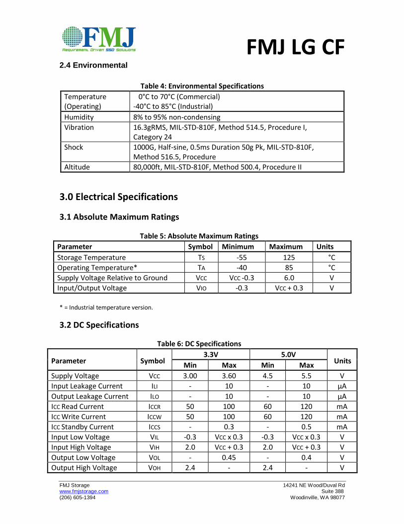
2.4 Environmental
Table 4: Environmental Specifications
Temperature (Operating)
0°C to 70°C (Commercial) -40°C to 85°C (Industrial)
Humidity 8% to 95% non-condensing
Vibration 16.3gRMS, MIL-STD-810F, Method 514.5, Procedure I, Category 24
Shock 1000G, Half-sine, 0.5ms Duration 50g Pk, MIL-STD-810F, Method 516.5, Procedure
Altitude 80,000ft, MIL-STD-810F, Method 500.4, Procedure II
3.0 Electrical Specifications
3.1 Absolute Maximum Ratings
Table 5: Absolute Maximum Ratings
Parameter Symbol Minimum Maximum Units
Storage Temperature TS -55 125 °C
Operating Temperature* TA -40 85 °C
Supply Voltage Relative to Ground VCC VCC -0.3 6.0 V
Input/Output Voltage VIO -0.3 VCC + 0.3 V
* = Industrial temperature version.
3.2 DC Specifications
Table 6: DC Specifications
Parameter
Symbol 3.3V 5.0V
Units Min Max Min Max
Supply Voltage VCC 3.00 3.60 4.5 5.5 V
Input Leakage Current ILI - 10 - 10 µA
Output Leakage Current ILO - 10 - 10 µA
ICC Read Current ICCR 50 100 60 120 mA
ICC Write Current ICCW 50 100 60 120 mA
ICC Standby Current ICCS - 0.3 - 0.5 mA
Input Low Voltage VIL -0.3 VCC x 0.3 -0.3 VCC x 0.3 V
Input High Voltage VIH 2.0 VCC + 0.3 2.0 VCC + 0.3 V
Output Low Voltage VOL - 0.45 - 0.4 V
Output High Voltage VOH 2.4 - 2.4 - V
FMJ LG CF
FMJ Storage 14241 NE Wood/Duval Rd www.fmjstorage.com Suite 388
(206) 605-1394 Woodinville, WA 98077
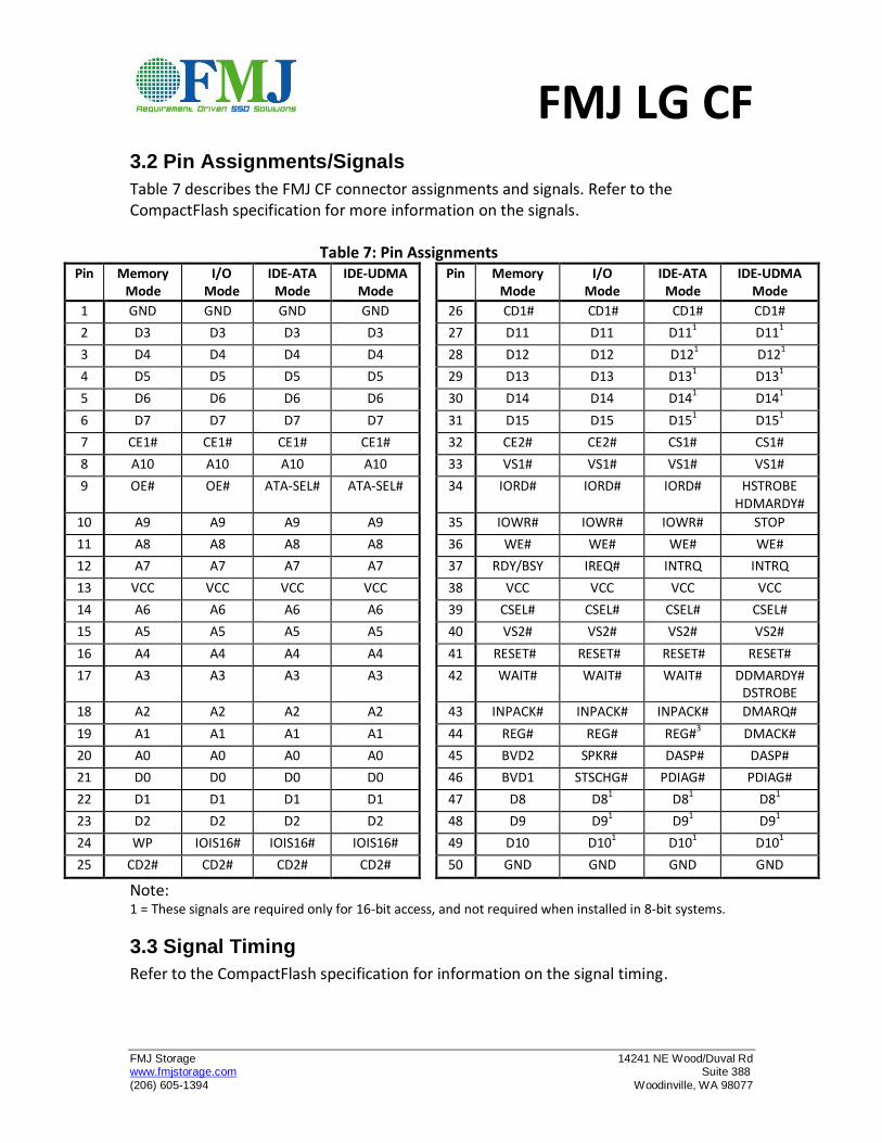
3.2 Pin Assignments/Signals
Table 7 describes the FMJ CF connector assignments and signals. Refer to the CompactFlash specification for more information on the signals.
Table 7: Pin Assignments Pin Memory
Mode I/O
Mode IDE-ATA
Mode IDE-UDMA
Mode
Pin Memory Mode
I/O Mode
IDE-ATA Mode
IDE-UDMA Mode
1 GND GND GND GND 26 CD1# CD1# CD1# CD1#
2 D3 D3 D3 D3 27 D11 D11 D111 D11
1
3 D4 D4 D4 D4 28 D12 D12 D121 D12
1
4 D5 D5 D5 D5 29 D13 D13 D131 D131
5 D6 D6 D6 D6 30 D14 D14 D141 D141
6 D7 D7 D7 D7 31 D15 D15 D151 D151
7 CE1# CE1# CE1# CE1# 32 CE2# CE2# CS1# CS1#
8 A10 A10 A10 A10 33 VS1# VS1# VS1# VS1#
9 OE# OE# ATA-SEL# ATA-SEL# 34 IORD# IORD# IORD# HSTROBE HDMARDY#
10 A9 A9 A9 A9 35 IOWR# IOWR# IOWR# STOP
11 A8 A8 A8 A8 36 WE# WE# WE# WE#
12 A7 A7 A7 A7 37 RDY/BSY IREQ# INTRQ INTRQ
13 VCC VCC VCC VCC 38 VCC VCC VCC VCC
14 A6 A6 A6 A6 39 CSEL# CSEL# CSEL# CSEL#
15 A5 A5 A5 A5 40 VS2# VS2# VS2# VS2#
16 A4 A4 A4 A4 41 RESET# RESET# RESET# RESET#
17 A3 A3 A3 A3 42 WAIT# WAIT# WAIT# DDMARDY# DSTROBE
18 A2 A2 A2 A2 43 INPACK# INPACK# INPACK# DMARQ#
19 A1 A1 A1 A1 44 REG# REG# REG#3 DMACK#
20 A0 A0 A0 A0 45 BVD2 SPKR# DASP# DASP#
21 D0 D0 D0 D0 46 BVD1 STSCHG# PDIAG# PDIAG#
22 D1 D1 D1 D1 47 D8 D81 D81 D81
23 D2 D2 D2 D2 48 D9 D91 D91 D91
24 WP IOIS16# IOIS16# IOIS16# 49 D10 D101 D101 D101
25 CD2# CD2# CD2# CD2# 50 GND GND GND GND
Note: 1 = These signals are required only for 16-bit access, and not required when installed in 8-bit systems.
3.3 Signal Timing
Refer to the CompactFlash specification for information on the signal timing.
FMJ LG CF
FMJ Storage 14241 NE Wood/Duval Rd www.fmjstorage.com Suite 388
(206) 605-1394 Woodinville, WA 98077
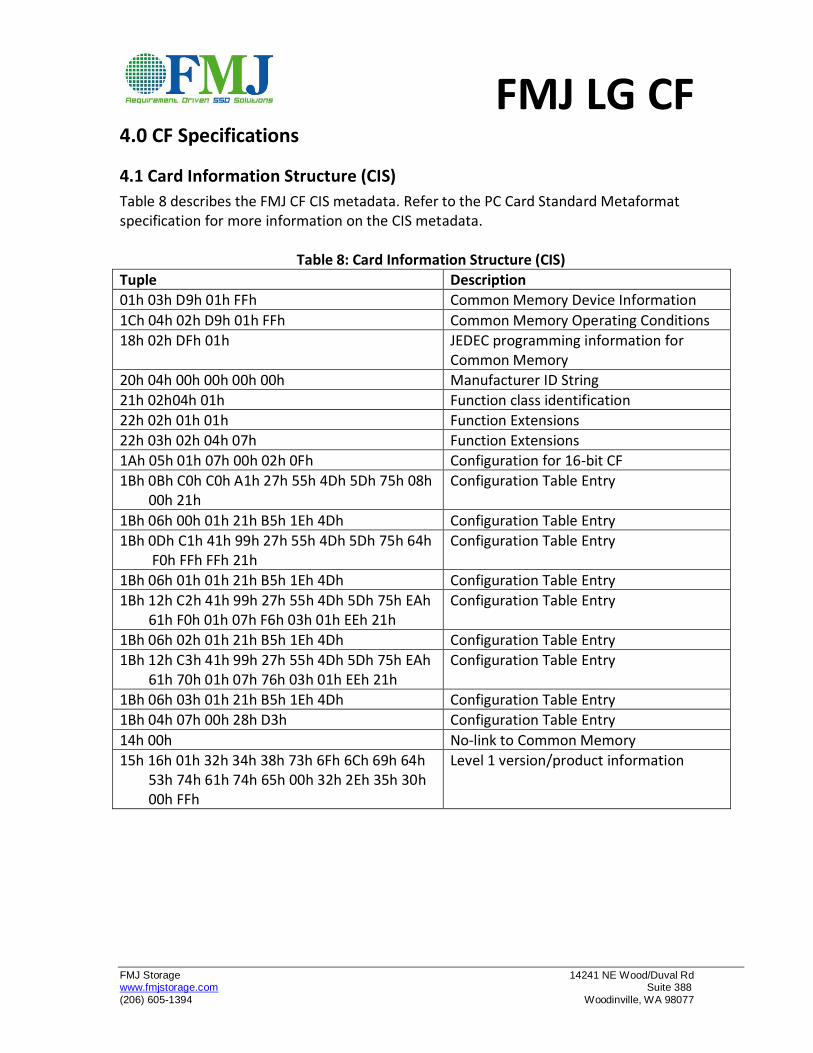
4.0 CF Specifications
4.1 Card Information Structure (CIS)
Table 8 describes the FMJ CF CIS metadata. Refer to the PC Card Standard Metaformat specification for more information on the CIS metadata.
Table 8: Card Information Structure (CIS)
Tuple Description
01h 03h D9h 01h FFh Common Memory Device Information
1Ch 04h 02h D9h 01h FFh Common Memory Operating Conditions
18h 02h DFh 01h JEDEC programming information for Common Memory
20h 04h 00h 00h 00h 00h Manufacturer ID String
21h 02h04h 01h Function class identification
22h 02h 01h 01h Function Extensions
22h 03h 02h 04h 07h Function Extensions
1Ah 05h 01h 07h 00h 02h 0Fh Configuration for 16-bit CF
1Bh 0Bh C0h C0h A1h 27h 55h 4Dh 5Dh 75h 08h 00h 21h
Configuration Table Entry
1Bh 06h 00h 01h 21h B5h 1Eh 4Dh Configuration Table Entry
1Bh 0Dh C1h 41h 99h 27h 55h 4Dh 5Dh 75h 64h F0h FFh FFh 21h
Configuration Table Entry
1Bh 06h 01h 01h 21h B5h 1Eh 4Dh Configuration Table Entry
1Bh 12h C2h 41h 99h 27h 55h 4Dh 5Dh 75h EAh 61h F0h 01h 07h F6h 03h 01h EEh 21h
Configuration Table Entry
1Bh 06h 02h 01h 21h B5h 1Eh 4Dh Configuration Table Entry
1Bh 12h C3h 41h 99h 27h 55h 4Dh 5Dh 75h EAh 61h 70h 01h 07h 76h 03h 01h EEh 21h
Configuration Table Entry
1Bh 06h 03h 01h 21h B5h 1Eh 4Dh Configuration Table Entry
1Bh 04h 07h 00h 28h D3h Configuration Table Entry
14h 00h No-link to Common Memory
15h 16h 01h 32h 34h 38h 73h 6Fh 6Ch 69h 64h 53h 74h 61h 74h 65h 00h 32h 2Eh 35h 30h 00h FFh
Level 1 version/product information
FMJ LG CF
FMJ Storage 14241 NE Wood/Duval Rd www.fmjstorage.com Suite 388
(206) 605-1394 Woodinville, WA 98077
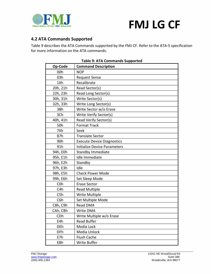
4.2 ATA Commands Supported
Table 9 describes the ATA Commands supported by the FMJ CF. Refer to the ATA-5 specification for more information on the ATA commands.
Table 9: ATA Commands Supported
Op-Code Command Description
00h NOP
03h Request Sense
1Xh Recalibrate
20h, 21h Read Sector(s)
22h, 23h Read Long Sector(s)
30h, 31h Write Sector(s)
32h, 33h Write Long Sector(s)
38h Write Sector w/o Erase
3Ch Write Verify Sector(s)
40h, 41h Read Verify Sector(s)
50h Format Track
7Xh Seek
87h Translate Sector
90h Execute Device Diagnostics
91h Initialize Device Parameters
94h, E0h Standby Immediate
95h, E1h Idle Immediate
96h, E2h Standby
97h, E3h Idle
98h, E5h Check Power Mode
99h, E6h Set Sleep Mode
C0h Erase Sector
C4h Read Multiple
C5h Write Multiple
C6h Set Multiple Mode
C8h, C9h Read DMA
CAh, CBh Write DMA
CDh Write Multiple w/o Erase
E4h Read Buffer
DEh Media Lock
DFh Media Unlock
E7h Flush Cache
E8h Write Buffer
FMJ LG CF
FMJ Storage 14241 NE Wood/Duval Rd www.fmjstorage.com Suite 388
(206) 605-1394 Woodinville, WA 98077
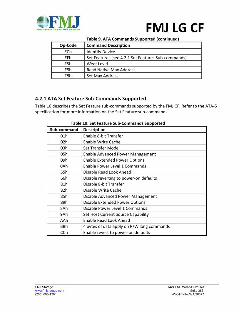
Table 9. ATA Commands Supported (continued)
Op-Code Command Description
ECh Identify Device
EFh Set Features (see 4.2.1 Set Features Sub-commands)
F5h Wear Level
F8h Read Native Max Address
F8h Set Max Address
4.2.1 ATA Set Feature Sub-Commands Supported
Table 10 describes the Set Feature sub-commands supported by the FMJ CF. Refer to the ATA-5 specification for more information on the Set Feature sub-commands.
Table 10: Set Feature Sub-Commands Supported
Sub-command Description
01h Enable 8-bit Transfer
02h Enable Write Cache
03h Set Transfer Mode
05h Enable Advanced Power Management
09h Enable Extended Power Options
0Ah Enable Power Level 1 Commands
55h Disable Read Look Ahead
66h Disable reverting to power-on defaults
81h Disable 8-bit Transfer
82h Disable Write Cache
85h Disable Advanced Power Management
89h Disable Extended Power Options
8Ah Disable Power Level 1 Commands
9Ah Set Host Current Source Capability
AAh Enable Read Look Ahead
BBh 4 bytes of data apply on R/W long commands
CCh Enable revert to power-on defaults
FMJ LG CF
FMJ Storage 14241 NE Wood/Duval Rd www.fmjstorage.com Suite 388
(206) 605-1394 Woodinville, WA 98077
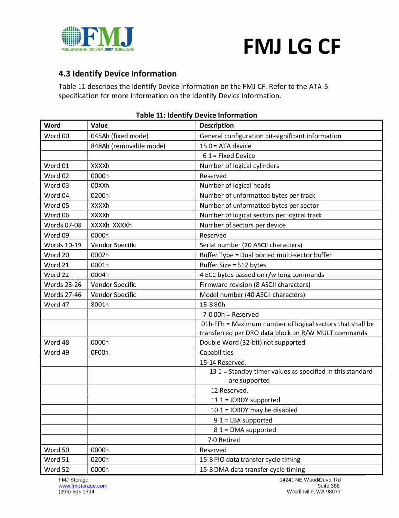
4.3 Identify Device Information
Table 11 describes the Identify Device information on the FMJ CF. Refer to the ATA-5 specification for more information on the Identify Device information.
Table 11: Identify Device Information
Word Value Description
Word 00 045Ah (fixed mode) General configuration bit-significant information
848Ah (removable mode) 15 0 = ATA device
6 1 = Fixed Device
Word 01 XXXXh Number of logical cylinders
Word 02 0000h Reserved
Word 03 00XXh Number of logical heads
Word 04 0200h Number of unformatted bytes per track
Word 05 XXXXh Number of unformatted bytes per sector
Word 06 XXXXh Number of logical sectors per logical track
Words 07-08 XXXXh XXXXh Number of sectors per device
Word 09 0000h Reserved
Words 10-19 Vendor Specific Serial number (20 ASCII characters)
Word 20 0002h Buffer Type = Dual ported multi-sector buffer
Word 21 0001h Buffer Size = 512 bytes
Word 22 0004h 4 ECC bytes passed on r/w long commands
Words 23-26 Vendor Specific Firmware revision (8 ASCII characters)
Words 27-46 Vendor Specific Model number (40 ASCII characters)
Word 47 8001h 15-8 80h
7-0 00h = Reserved
01h-FFh = Maximum number of logical sectors that shall be transferred per DRQ data block on R/W MULT commands
Word 48 0000h Double Word (32-bit) not supported
Word 49 0F00h Capabilities
15-14 Reserved.
13 1 = Standby timer values as specified in this standard are supported
12 Reserved.
11 1 = IORDY supported
10 1 = IORDY may be disabled
9 1 = LBA supported
8 1 = DMA supported
7-0 Retired
Word 50 0000h Reserved
Word 51 0200h 15-8 PIO data transfer cycle timing
Word 52 0000h 15-8 DMA data transfer cycle timing
FMJ LG CF
FMJ Storage 14241 NE Wood/Duval Rd www.fmjstorage.com Suite 388
(206) 605-1394 Woodinville, WA 98077
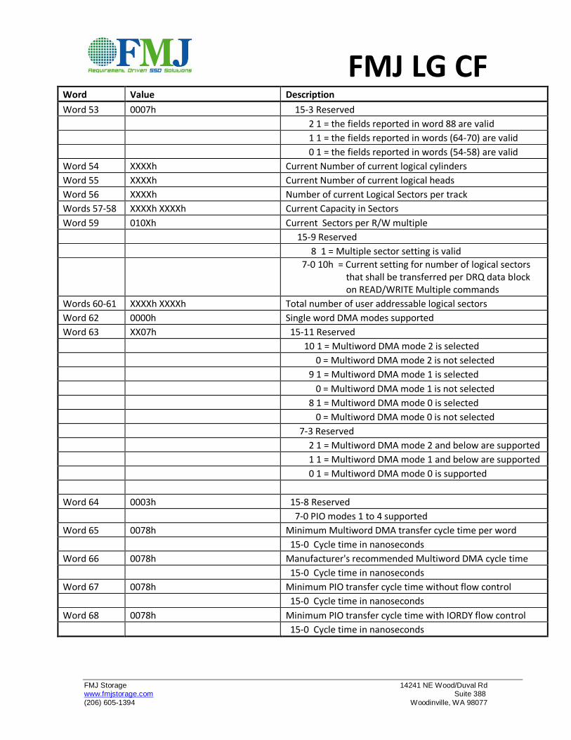
Word Value Description
Word 53 0007h 15-3 Reserved
2 1 = the fields reported in word 88 are valid
1 1 = the fields reported in words (64-70) are valid
0 1 = the fields reported in words (54-58) are valid
Word 54 XXXXh Current Number of current logical cylinders
Word 55 XXXXh Current Number of current logical heads
Word 56 XXXXh Number of current Logical Sectors per track
Words 57-58 XXXXh XXXXh Current Capacity in Sectors
Word 59 010Xh Current Sectors per R/W multiple
15-9 Reserved
8 1 = Multiple sector setting is valid
7-0 10h = Current setting for number of logical sectors that shall be transferred per DRQ data block on READ/WRITE Multiple commands
Words 60-61 XXXXh XXXXh Total number of user addressable logical sectors
Word 62 0000h Single word DMA modes supported
Word 63 XX07h 15-11 Reserved
10 1 = Multiword DMA mode 2 is selected
0 = Multiword DMA mode 2 is not selected
9 1 = Multiword DMA mode 1 is selected
0 = Multiword DMA mode 1 is not selected
8 1 = Multiword DMA mode 0 is selected
0 = Multiword DMA mode 0 is not selected
7-3 Reserved
2 1 = Multiword DMA mode 2 and below are supported
1 1 = Multiword DMA mode 1 and below are supported
0 1 = Multiword DMA mode 0 is supported
Word 64 0003h 15-8 Reserved
7-0 PIO modes 1 to 4 supported
Word 65 0078h Minimum Multiword DMA transfer cycle time per word
15-0 Cycle time in nanoseconds
Word 66 0078h Manufacturer's recommended Multiword DMA cycle time
15-0 Cycle time in nanoseconds
Word 67 0078h Minimum PIO transfer cycle time without flow control
15-0 Cycle time in nanoseconds
Word 68 0078h Minimum PIO transfer cycle time with IORDY flow control
15-0 Cycle time in nanoseconds
FMJ LG CF
FMJ Storage 14241 NE Wood/Duval Rd www.fmjstorage.com Suite 388
(206) 605-1394 Woodinville, WA 98077
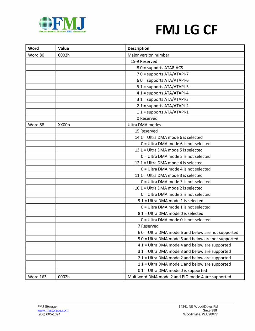
Word Value Description
Word 80 0002h Major version number
15-9 Reserved
8 0 = supports ATA8-ACS
7 0 = supports ATA/ATAPI-7
6 0 = supports ATA/ATAPI-6
5 1 = supports ATA/ATAPI-5
4 1 = supports ATA/ATAPI-4
3 1 = supports ATA/ATAPI-3
2 1 = supports ATA/ATAPI-2
1 1 = supports ATA/ATAPI-1
0 Reserved
Word 88 XX00h Ultra DMA modes
15 Reserved
14 1 = Ultra DMA mode 6 is selected
0 = Ultra DMA mode 6 is not selected
13 1 = Ultra DMA mode 5 is selected
0 = Ultra DMA mode 5 is not selected
12 1 = Ultra DMA mode 4 is selected
0 = Ultra DMA mode 4 is not selected
11 1 = Ultra DMA mode 3 is selected
0 = Ultra DMA mode 3 is not selected
10 1 = Ultra DMA mode 2 is selected
0 = Ultra DMA mode 2 is not selected
9 1 = Ultra DMA mode 1 is selected
0 = Ultra DMA mode 1 is not selected
8 1 = Ultra DMA mode 0 is selected
0 = Ultra DMA mode 0 is not selected
7 Reserved
6 0 = Ultra DMA mode 6 and below are not supported
5 0 = Ultra DMA mode 5 and below are not supported
4 1 = Ultra DMA mode 4 and below are supported
3 1 = Ultra DMA mode 3 and below are supported
2 1 = Ultra DMA mode 2 and below are supported
1 1 = Ultra DMA mode 1 and below are supported
0 1 = Ultra DMA mode 0 is supported
Word 163 0002h Multiword DMA mode 2 and PIO mode 4 are supported
FMJ LG CF
FMJ Storage 14241 NE Wood/Duval Rd www.fmjstorage.com Suite 388
(206) 605-1394 Woodinville, WA 98077
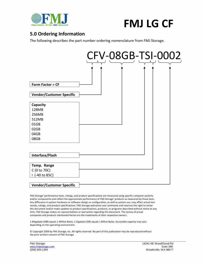
5.0 Ordering Information The following describes the part number ordering nomenclature from FMJ Storage.
CFV-08GB-TSI-0002
Form Factor = CF
Vendor/Customer Specific
Capacity 128MB 256MB 512MB 01GB 02GB 04GB 08GB
Interface/Flash
Temp. Range C (0 to 70C) I (-40 to 85C)
Vendor/Customer Specific FMJ Storage' performance tests, ratings, and product specifications are measured using specific computer systems and/or components and reflect the approximate performance of FMJ Storage’ products as measured by those tests. Any difference in system hardware or software design or configuration, as well as system use, may affect actual test results, ratings, and product specifications. FMJ Storage welcomes user comments and reserves the right to revise this document and/or make updates to product specifications, products, or programs described without notice at any time. FMJ Storage makes no representations or warranties regarding this document. The names of actual companies and products mentioned herein are the trademarks of their respective owners. 1 Megabyte (MB) equals 1 Million Bytes; 1 Gigabyte (GB) equals 1 Billion Bytes. Accessible capacity may vary depending on the operating environment. © Copyright 2009 by FMJ Storage, Inc. All rights reserved. No part of this publication may be reproduced without the prior written consent of FMJ Storage.