fme desktop 2013 editioncdn.safe.com/training/course-materials/fme-desktop... · 2013-01-30 · fme...
TRANSCRIPT

FME®
Desktop Training Workbook
FME Desktop 2013 Edition

ii
Safe Software Inc. makes no warranty either expressed or implied, including, but not limited to, any implied warranties of merchantability or fitness for a particular purpose regarding these materials, and makes such materials available solely on an “as-is” basis.
In no event shall Safe Software Inc. be liable to anyone for special, collateral, incidental, or consequential damages in connection with or arising out of purchase or use of these materials. The sole and exclusive liability of Safe Software Inc., regardless of the form or action, shall not exceed the purchase price of the materials described herein.
This manual describes the functionality and use of the software at the time of publication. The software described herein, and the descriptions themselves, are subject to change without notice.
Any spatial data included in this material is intended for training use only. It is not meant to accurately reflect any real life situation and may have been altered in some way from the original source data.
Much of the data used here originates from public domain data made available by the City of Austin and Travis County, Texas. The datasets can be found at:
ftp://ftp.ci.austin.tx.us/GIS-Data/Regional/coa_gis.html
Copyright
© 1994–2013 Safe Software Inc. All rights are reserved.
Revisions
Every effort has been made to ensure the accuracy of this document. Safe Software Inc. regrets any errors and omissions that may occur and would appreciate being informed of any errors found. Safe Software Inc. will correct any such errors and omissions in a subsequent version, as feasible. Please contact us at:
Safe Software Inc. Suite 2017, 7445 – 132nd Street Surrey, BC Canada V3W1J8
fax: 604-501-9965 e-mail: [email protected]
www.safe.com
Safe Software Inc. assumes no responsibility for any errors in this document or their consequences, and reserves the right to make improvements and changes to this document without notice.
Trademarks
FME® and SpatialDirect® are registered trademarks of Safe Software Inc. All brand or product names are trademarks or registered trademarks of their respective holders and should be noted as such.
Document Information
Document Name: FME Desktop Training Workbook 2013 Version: FME Desktop 2013 Updated: January 2013

FME Desktop Training Workbook
Training Exercises
FME Desktop Training Workbook .................................................................................................................... 3
This Workbook .............................................................................................................................................................. 3 Scenario ........................................................................................................................................................................ 3
Session 2 – Data Transformation .................................................................................................................... 5 Objective ....................................................................................................................................................................... 5 Detailed Steps ............................................................................................................................................................... 6 Advanced Tasks .......................................................................................................................................................... 13
Session 3 – Translation Components ............................................................................................................ 14 Objective ..................................................................................................................................................................... 14 Detailed Steps ............................................................................................................................................................. 14 Advanced Task 1 ........................................................................................................................................................ 19 Advanced Task 2 ........................................................................................................................................................ 20
Session 4 – Datasets and Feature Types ...................................................................................................... 22 Objective ..................................................................................................................................................................... 22 Detailed Steps ............................................................................................................................................................. 22 Advanced Tasks .......................................................................................................................................................... 25
Session 5 – Practical Transformer Use ......................................................................................................... 26 Objective ..................................................................................................................................................................... 26 Detailed Steps ............................................................................................................................................................. 26 Advanced Task ........................................................................................................................................................... 30
Session 6 – Best Practice .............................................................................................................................. 32 Objective ..................................................................................................................................................................... 32 Detailed Steps ............................................................................................................................................................. 32 Advanced Tasks .......................................................................................................................................................... 36
Session 7 – Group Project ............................................................................................................................. 37 Task 1: Data Preparation ............................................................................................................................................ 38 Task 2: Data Extraction ............................................................................................................................................... 40 Task 3: Schema Definition and Schema Mapping ...................................................................................................... 42 Advanced Tasks .......................................................................................................................................................... 44

FME Desktop Training Workbook
Page 2 Training Exercises

Training Exe
FME Desk
This WorkbEach exercis Scenario All exercisesInteropolis. As an FME uand produce
ercises
ktop Trainin
book se in this wor
s are based o
user with the e output for ot
ng Workboo This woconjunc
rkbook relates
on the scenari
City of Interother departme
ok
orkbook contction with the
s to a differen
io that you wo
opolis, you areents within yo
tains the exehe FME Desk
nt FME Deskto
ork as a GIS T
e using Workbour organizatio
FME D
xercises to bktop training
op training se
Technician at
bench to tranon.
esktop Training W
be performedg sessions.
ession.
t the fictional
slate source d
Workbook
Page 3
d in
city of
data

FME Desktop Training Workbook
Page 4 Training Exercises

Training Exe
Session 2
Scenario
Data
Overall Goal
Starting Wor
Finished Workspaces
Objective In this exercproperty lot The validatio a) Test that
b) Test each The gap is fibut the middhas none at
ercises
– Data Tra
FM
Pro
ConGoo
kspaces Non
C:\FC:\F
cise you have lines dataset,
on tests to be
t each proper
h property h
ixed, but theredle polygon ha
all (perhaps
ansformatio This execlean up
Exer
E user; City of
operty lot lines
nvert a set of pogle Earth KML
ne
FMEData\WorFMEData\Wor
been given a, and, at the s
e carried out a
rty can be fo
as a single c
e are more pras two centroit was accide
on
ercise involvp some spat
rcise: Data Tra
Interopolis, Pl
(MapInfo MIF
property lines iL format; simu
rkspaces\Desktrkspaces\Deskt
an urgent tasksame time, va
are as follows
ormed into a Here is a sThe bottomprevents aproblem w
centroid (poi
roblems. Theoids (not one),ntally placed
ves using tratial data and
nsformation
anning Depart
); Google Earth
n MapInfo MIFltaneously vali
topWorkbook\topWorkbook\
k of convertinalidating the d
.
unique polyg
set of data shom property bo polygon beine need to val
int feature) in
upper polygo, and the lowetoo far north?
FME D
ansformers td its associa
tment
h KML
F format, to a sidating geome
\Exercise1aCom\Exercise1bCom
g a Planning dataset’s geom
ygon.
own as lines oundary must ng formed. Thidate against
nside of it.
on is correct, er polygon ?)
esktop Training W
to validate aated attribute
set of polygonstry and attribu
mplete.fmwmplete.fmw
Department metry and attr
and then polyhave a gap th
his is the sort .
Workbook
Page 5
and tes.
s in utes.
ributes.
ygons. hat of

FME Desktop Training Workbook
Page 6 Training Exercises
c) Test that each property in a block has a common Block ID number. These three properties form a single block, but the lower property has a problem (again!). This time it’s a different block ID number. Detailed Steps 1) Inspect the Source Data Inspecting the source data with the FME Universal Viewer before a translation should now be automatic. Start the FME Universal Viewer and use it to open the source dataset. Query some features to become familiar with the geometry and attributes that exist. The source data here is: Reader Format MapInfo MIF/MID Reader Dataset C:\FMEData\Data\Properties\parcel_L26.mif 2) Create a New Workspace Start Workbench and create a workspace to translate the source data (parcel_L26) to: Writer Format Google Earth KML Writer Dataset C:\FMEData\Output\DesktopTraining\Parcels.kml Save the workspace. 3) Place a Transformer – GeometryFilter From inspecting the data you will have noticed that both line and point features occupy a single layer (feature type). However, only the line features are needed to build polygons. In workspace authoring it’s often useful to run the workspace after every step, without writing data. So, first delete the existing connection between reader and writer feature types. Now add a GeometryFilter transformer using Quick Add to place it unconnected onto the canvas. Then connect the GeometryFilter to the reader feature type.

Training Exe
4) Place a TAdd an Area Ultimately thconnect the The most effdo this is wit Click the outmarked LINEtyping ‘areabcanvas. The workspa
5) Check thParametersThe yellow cicon indicateto be checke Open the Ardialog by clic You don’t nethat field emcan be set to The yellow icshould now parameters the workspa
ercises
Transformer aBuilder trans
he GeometryFAreaBuilder o
ficient way toth Quick-Add.
tput port E and start bu’ on the
ace will now l
he Transforms color of the Ares some paraed.
reaBuilder Packing the yello
eed a Group-Bmpty, and Crea
o no.
con on the Arturn blue indihave been ch
ace is ready to
– AreaBuildesformer to turn
Filter transformonto the port
.
ook somethin
mer
reaBuilder meters need
arameters ow icon.
By so leave ate Donuts
reaBuilder cating the hecked and o run.
er n the lot linew
mer will be usGeometryFilt
ng like this:
work into lot p
sed to keep linter:LINE.
FME D
olygons.
nes, but filter
esktop Training W
out points, so
Workbook
Page 7
o

FME Desktop T
Page 8
6) Place TraAt this point the output is
Inspectors aautomaticall NB: The <Rare being filt 7) Run the WClick the Ru 8) Check thWell, polygo For a geomeViewer and c In a real-life your choice,
Training Workboo
ansformers –you can try th
s always a goo
are connectedy.
REJECTED> ptered out by th
Workspace n button on th
he Output ons have been
etry check, tucheck for any
situation you so that it can
ok
– Inspectorshe workspaceod step to tak
d and named
port is for featthe Geometry
he Workbenc
n formed, but
rn off the polyy unused lines
might now un be sent to a
e, but sendingke before writ
Rth
tures from whyFilter, there s
ch toolbar or c
t there are two
ygon layer in s.
se File > Sava data editor fo
g the data to ting the outpu
Right-click thehe option to C
hich polygonsshould be no s
choose File >
o things to ch
FME Univers
ve Data As toor fixing.
FME Universut for real.
title of the ArConnect Insp
s cannot be busuch features
> Run from the
heck: geometr
sal
o save unused
For an athe polygand quewhat attr
Training Ex
al Viewer to c
reaBuilder anpectors.
uilt. Because s in the outpu
e menu bar.
ry and attribut
d lines in a fo
attribute checkgon layer bacry a feature toributes it has
xercises
check
nd select
these t.
tes.
ormat of
k, turn ck on o see (if any)
Training Exe
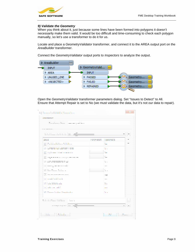
9) Validate When you thnecessarily manually, so Locate and pAreaBuilder Connect the
Open the GeEnsure that
ercises
the Geometrhink about it, jmake them vao let’s use a tr
place a Geomtransformer.
e GeometryVa
eometryValidAttempt Repa
ry just because alid. It would ransformer to
metryValidato
alidator outpu
ator transformair is set to N
some lines hbe too difficu
o do it for us.
r transformer
t ports to Insp
mer parameteo (we must v
ave been formlt and time-co
, and connec
pectors to ana
ers dialog. Setalidate the da
FME D
med into polyonsuming to c
t it to the ARE
alyze the outp
t “Issues to Data, but it’s no
esktop Training W
ygons it doesncheck each po
EA output por
put.
Detect” to All.ot our data to
Workbook
Page 9
n’t olygon
rt on the
repair).

FME Desktop Training Workbook
Page 10 Training Exercises
10) Run the Workspace Again Run the workspace and check for invalid features. Even if you can’t see a fault in the highlighted features, query them and check their attributes; the GeometryValidator transformer adds an attribute to indicate the problem(s) and which test(s) was failed . Again, in the real world the FAILED features would probably be saved for further examination. 11) Place a Transformer – PointOnAreaOverlayer If you looked carefully during the data inspection, then the lack of attributes is no surprise because you’d have noticed it was the polygon centroids (point features) that held the attributes, not the line features. So the next task is to get the attributes off the point features and onto the new polygons. The PointOnAreaOverlayer transformer transfers attributes from points onto surrounding areas. Use whatever method you prefer to locate the PointOnAreaOverlayer transformer and place one into an empty part of the workspace. 12) Correct Connections This is where you start to use transformers in parallel. Connect GeometryFilter:POINT to the input port PointOnAreaOverlayer:POINT Connect GeometryValidator:PASSED to the input port PointOnAreaOverlayer:AREA Check the PointOnAreaOverlayer parameters (see the yellow button) and accept the defaults. At this point your workspace will look like this:

FME Desktop Training Workbook
Training Exercises Page 11
13) Run the Workspace Connect up some Inspectors and run the workspace again. 14) Check the Output Query a feature. That’s much better. Polygons were formed with the correct attributes.
However – have you noticed anything about the Feature Counts on the completed translation? Do the numbers reveal anything about the quality of the output?
15) Place a Transformer – Tester Well done if you noticed the problem: 1570 area features but only 1512 point features. This means a number of area features are without a centroid, and therefore without attributes. Potentially it’s worse – what if areas are overlapping and sharing the same centroid? Let’s test for polygons without a one-to-one match. Place a Tester transformer on the canvas. Connect it to the PointOnAreaOverlayer:AREA port. See if you can figure out how to set up the Tester before looking at the next step! 16) Check the Transformer Parameters Did you figure it out? Importantly the PointOnAreaOverlayer adds a new attribute called _overlaps. This tells you how many points were found inside each area. Set the Tester properties with the required test: _overlaps = 1

FME Desktop Training Workbook
Page 12 Training Exercises
17) Identify Bad Output Bad features (those where the number of overlaps is zero, or more than one) will emerge from the Tester:FAILED port. Let’s run the workspace to identify bad output quickly. Delete any existing Inspectors then add two more; one to the port Tester:FAILED and another to PointOnAreaOverlayer:POINT (inspecting the points is necessary to see why the areas failed). Run the workspace and examine the bad data. How many bad features are there? 18) Make Final Connections Now we’ve filtered out all of the bad data, we can make a final connection to the output dataset. Connect the output port Tester:PASSED to the destination feature type OGCKML:parcel_k26 Delete any existing Inspectors.
19) Save and Run the Workspace Save the workspace using the Save button on the toolbar. Run the workspace again. 20) Check the Output Inspect the output data to prove that it only contains polygon features with attributes. Open it in Google Earth to make sure it is in the correct location.

Training Exe
Advanced TOoops! We As an advanway that a u The simplesAggregator t So, does eveblock have t Similarly, doa unique ID?
ercises
Tasks haven’t done
nced task, devser could spo
st approach istransformer a
ery property ithe same ID?
oes every bloc?
the final test
vise a way to ot wrongly nu
s to group likeand the BLOC
n every
ck have
– that each b
inspect the dmbered prope
e features togeCK_ID attribut
block of prope
data in the FMerties.
ether in somete) then apply
FME D
erties has a u
ME Universal V
e way (probabying a differen
esktop Training W
nique ID num
Viewer, in su
bly using an nt color per fe
Workbook
Page 13
mber
ch a
ature.

FME Desktop T
Page 14
Session 3
Scenario
Data
Overall Goal
Starting Wor
Finished Workspaces
Objective A communic(mobile phonhigh an elev You have be In this exerc• Read a • Filter ou• Overlay • Select th Detailed Ste1) Inspect thInspecting thautomatic. Start the FMbecome fam The source dReader ForReader Data Reader ForReader Data
Training Workboo
– Translat
FM
Lan
Compot
kspaces Non
C:\FC:\FC:\FC:\F
cations compane) masts. Th
vation as poss
een tasked wi
cise, you’ll fulfsource datas
ut unsuitable sthe data onto
he top ten site
eps the Source Dhe source dat
ME Universal Vmiliar with the
data here is: mat Aaset C
mat Caset C
ok
ion Compo Here’s aformats
Exerci
E user; City of
ndmarks (AutoC
mpare landmatential cell pho
ne
FMEData\WorFMEData\WorFMEData\WorFMEData\Wor
any is negotiahe ideal positisible.
ith creating an
fill the followinet of local lansites such as o a raster DEes in terms of
Data ta with the FM
Viewer and usgeometry and
Autodesk AutC:\FMEData\D
Canadian DigC:\FMEData\D
nents
an exercise ws within FME
se: Translation
Interopolis, Pl
CAD DWG), Ele
rks against an one (mobile ph
rkspaces\Desktrkspaces\Desktrkspaces\Desktrkspaces\Deskt
ating with the ions are on p
n FME works
ng objectives:ndmarks. schools. M to assign ef elevation.
ME Universal
se it to open td attributes th
oCAD DWG/DData\Landma
gital ElevationData\Elevatio
with tasks tE.
n Components
anning Depart
evation Model
elevation modone) masts.
topWorkbook\topWorkbook\topWorkbook\topWorkbook\
city to find loublically owne
pace to pick o
:
elevation to ea
Viewer befor
the source dahat exist.
DXF arks\Landmark
Data (CDEDonModel\Raste
that gently s
s
tment
(CDED Raster)
del to find prom
\Exercise2aCom\Exercise2bCom\Exercise2cCom\Exercise2dCom
cations to poed, prominen
out likely sites
ach landmark
e a translatio
atasets. Quer
rks.dwg
D) erDEM-250K
Training Ex
stretch your
)
minent position
mplete.fmw mplete.fmw mplete.fmw mplete.fmw
sition cell phot landmarks a
s for further a
k.
n should now
ry some featu
K.dem
xercises
r use of
ns for
one at as
analysis.
w be
res to

FME Desktop Training Workbook
Training Exercises Page 15
2) Start Workbench Start Workbench. Create a workspace to translate the AutoCAD landmarks data; namely: Reader Format Autodesk AutoCAD DWG/DXF Reader Dataset C:\FMEData\Data\Landmarks\Landmarks.dwg Reader Parameters Group Entities By: Attribute Schema Writer Format Adobe 3D PDF Writer Dataset C:\FMEData\Output\DesktopTraining\Cellmasts.pdf 3) Place a Tester While inspecting the data you should have noticed that there is an attribute called LANAME – this represents the name of the landmark feature. One task is to filter out landmarks which have:
• No name (i.e. no value for LANAME) • The word “School” in the name
…as City council has determined that no cell-phone masts should be erected on school property. Place a Tester transformer with the PASSED output port connected to the output. The test will be set up so that the features we want will pass the test.
Set up two tests:
• LANAME Attribute Is Empty • LANAME Contains School
Then click the Negate option for both of these. That way we will cause these features to FAIL.
Be sure to set up the Pass Criteria field as “All Tests (AND)”; i.e. filter where LANAME is not empty AND it doesn’t contain the word “School”.
This is a very interesting test of logic.
If the tests were not negated, then the pass criteria should be OR.
But, because the tests are negated, the pass criteria should be AND Basically, if you negate multiple tests, you’ll want to switch from OR to AND. Can you see why this might be?
FME Desktop Training Workbook
Page 16 Training Exercises
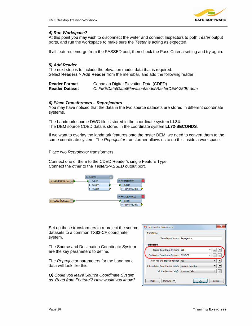
4) Run Workspace? At this point you may wish to disconnect the writer and connect Inspectors to both Tester output ports, and run the workspace to make sure the Tester is acting as expected. If all features emerge from the PASSED port, then check the Pass Criteria setting and try again. 5) Add Reader The next step is to include the elevation model data that is required. Select Readers > Add Reader from the menubar, and add the following reader: Reader Format Canadian Digital Elevation Data (CDED) Reader Dataset C:\FMEData\Data\ElevationModel\RasterDEM-250K.dem 6) Place Transformers – Reprojectors You may have noticed that the data in the two source datasets are stored in different coordinate systems. The Landmark source DWG file is stored in the coordinate system LL84. The DEM source CDED data is stored in the coordinate system LL72-SECONDS. If we want to overlay the landmark features onto the raster DEM, we need to convert them to the same coordinate system. The Reprojector transformer allows us to do this inside a workspace. Place two Reprojector transformers. Connect one of them to the CDED Reader’s single Feature Type. Connect the other to the Tester:PASSED output port.
Set up these transformers to reproject the source datasets to a common TX83-CF coordinate system. The Source and Destination Coordinate System are the key parameters to define. The Reprojector parameters for the Landmark data will look like this: Q) Could you leave Source Coordinate System as ‘Read from Feature’? How would you know?

FME Desktop Training Workbook
Training Exercises Page 17
7) Run Workspace To ensure the Reprojector transformers are working as expected, connect them both to Inspector transformers and re-run the workspace. If the data is reprojected correctly, both sets of features appear in the same coordinate space. 8) Place a Transformer – PointOnRasterValueExtractor To assign elevation to landmark data, we need to overlay it onto the DEM and extract a Z value. Place a PointOnRasterValueExtractor transformer. Use its default parameter values. Connect the landmark REPROJECTED data to the PointOnRasterValueExtractor:POINT input port, and the elevation model REPROJECTED to PointOnRasterValueExtractor:RASTER.
Again, connect an Inspector to the PointOnRasterValueExtractor and run the workspace to inspect what data the process has created so far. The resulting attribute from this operation is called ‘_band{0}.value’.
The attribute is called ‘_band{0}.value’ because it’s the first band (layer) of the raster. In fact this layer of DEM values is the only band here. A three-band color raster dataset would produce _band{0}.value, _band{1}.value, and _band{2).value for the colors Red, Green, and Blue. 9) Place a Transformer – 3DForcer The elevation can now be used to provide the output features with a proper Z value. Place a 3DForcer transformer. For elevation click on Set To Attribute Value and select _band{}.value:
You will be prompted to select the element in the list that you wish to use. In this instance, choose 0 (the only list element that will actually have a value).

FME Desktop Training Workbook
Page 18 Training Exercises
Once more, connect an Inspector and run the workspace. Querying a feature should show that each landmark feature now has a Z coordinate.
The last part of the workspace will now look something like this: 10) Place Transformers – Sorter and Sampler Not much work left now: we just need to select the top 10 sites in terms of elevation. Place a Sorter transformer and set it up to sort features in order of elevation – highest to lowest.
Place a Sampler transformer and set it up to pass only the first 10 features in the workflow.
11) Reconnect Writer Reconnect the writer, and delete any remaining Inspectors. The workspace should now look something like this:
12) Run Workspace Save and run the workspace, and inspect the output.

Training Exe
Advanced TWhen inspectells us what(being from By checkingwe can mak 1) Expose FCheck if the cded_units i If not, click ttab on the Cproperties dcheckmark nattribute to e
The test clau 3) Place a TIf a feature f
Set up the tr(_band{0}.va(3.2808) and Save and rudifference th
ercises
Task 1 cting the datat units the elethe US) is in
the value of e the workspa
Format Attribformat attribus already exp
he Format AtCDED source
ialog. Put a next to the forexpose it.
2) Placde If s
use will look l
Transformer fails the test –
ransformer toalue) by the nd write to _ba
n the worksphis update has
a you may havevation valuesfeet, but this
the attribute, ace imperviou
bute ute posed.
ttributes
rmat
Place a Tranace a Tester aed_units = fe
so (PASSED)
ike this:
– Expression– its units are
multiply the inumber of feeand{0}.value.
ace. Check tos made.
ve noticed a Cs are in the damight not be
and convertinus if used on
nsformer – Tafter the Poinet.
) the features
nEvaluator metres and n
input attributet per metre
o see what
CDED formatata. At the mothe case…
ng elevation fsource datas
Tester ntOnRasterVa
can proceed
not feet – then
Place a Connecport, an
e
FME D
t attribute calloment we mig
from metres tsets with diffe
alueExtractor
to the 3DFor
n we need to
an Expression
ct it to the Tesnd then to 3DF
esktop Training W
led cded_unitght assume th
to feet if necerent units.
transformer t
rcer.
convert the u
nEvaluator.
ster:FAILED oForcer:INPUT
Workbook
Page 19
ts. This he data
essary,
to test if
units.
output T.

FME Desktop T
Page 20
Advanced TIt would be udata. As a ra 1) Create WCreate a newType). Conn By default, wband of elevwarning that Unsupporte 2) Place a TTo change t Set the interred, green a
This, with thbetween 0 a
Training Workboo
Task 2 useful to writeaster-support
Writer Featurew writer featunect the repro
writing the Ravations not reat states as mu
d number of
Transformer he data to a c
rpretation typeand blue value
e Conversionand 255.
ok
e a little more ing format, th
e Type ure type (eitheojected CDED
aster data direally compatibuch:
f bands: 1.
– RasterIntecolor raster pl
e to RGB24. Tes from 0 to 2
n Options, will
output than jhe PDF writer
er duplicate thD data to it.
ectly to PDF isle with PDF.
Only raste
erpretationColace a Raster
This means 3255 (2^8 - 1)
l convert the n
Now we
ust 10 point fis ideal for th
he existing on
s not going toIf you run the
ers with 3 o
oercer rInterpretation
3x8 bit bands
numeric value
e have a raste
features, to gihis.
ne, or use Wri
o be much usee workspace,
or 4 bands
nCoercer.
representing
es into color,
er backdrop to
Training Ex
ive a backdro
iters > Add F
e, as it is a sithe log has a
are support
scaling the Z
o the point da
xercises
op to the
Feature
ngle-
ted.
Z value
ata

Training Exe
However, th 3) Place a TReplace the Connect theTINGenerato Set the TING
4) Place a TThe output fexaggerate t Place a Scaand set it to Now when y
ercises
at solution do
Transformer RasterInterp
e reprojected ror:TIN_SURF
Generator Su
Transformer from this workthe Z scale to
ler transformescale the Z v
you run the wo
oesn’t make u
– TINGenerapretationCoerc
raster to TINGFACE to the w
rface Toleran
– Scaler kspace is nowo show the re
er AFTER thevalue by a fac
orkspace the
use of the 3D
ator cer with a TIN
Generator:POwriter feature
nce paramete
w a bit flat (runlief a little bet
e TINGeneratctor of 20.
PDF will hav
nature of PD
NGenerator tr
OINTS/LINEStype.
r to 5
n it and checktter.
tor
ve a full 3D ba
NB:valuethem(andversi
FME D
F. We can re
ansformer.
S and then
k if you like).
ackdrop to the
You’ll have toes of the poin
m on top of thed scale the feeions differentl
esktop Training W
medy that!
It would be he
e point data.
o also scale thnts if you wane raster backdet and metresly)!
Workbook
Page 21
elpful to
he Z t to see drop
s

FME Desktop T
Page 22
Session 4
Scenario
Data
Overall Goal
Starting Wor
Finished Workspaces
Objective When a propprovide a se Your currentto the City’s By doing this• Set up a• Add a ne• Clean al• Use a C• Add a ne Detailed Ste1) Open a BStart Workbe 2) Add a ReFirst we’ll seon the menu Reader ForReader Data Workflow O
Training Workboo
– Datasets
FM
Pro
Com
kspaces Non
C:\FC:\F
perty developet of new prop
t task is to seproperty map
s, you’ll achiea workspace tew Reader toll source data
ChangeDetectew Writer to w
eps Blank Workspench and beg
eader et up the worku bar. Add a n
mat Masets A
Option S
ok
s and Featu This exehave jus
Exercise
E user; City of
operty lot lines
mpare develop
ne
FMEData\WorFMEData\Wor
per submits a perty boundar
t up an FME p, to determin
eve the followto read the cito read the deva to ensure a tor transformewrite the data
pace gin with a blan
kspace to readnew reader to
MapInfo MIF/MAll MIF files in
Single Merged
ure Types
ercise makest learned to
e: Datasets and
Interopolis, Pl
(MapInfo MIF
per proposals a
rkspaces\Desktrkspaces\Deskt
planning appries to update
solution that wne which featu
wing objectivesty’s current prveloper’s DXFbetter match.er to comparea to DGN form
nk workspace
d the city’s bao the workspa
MID n the folder C
d Feature Typ
es use of theo do a chang
d Feature Type
anning Depart
, AutoCAD DW
against a base d
topWorkbook\topWorkbook\
plication to thee the city’s rec
will compare ures to upload
s: roperty datasF dataset. . e city data to tmat.
e.
ase datasets.ce to read the
:\FMEData\D
pe
e dataset relge detection
es
tment
WG)
dataset to dete
\Exercise3aCom\Exercise3bCom
e City of Intercords.
a set of deved and replace
ets (MIF/MID
the developer
Select Reade following pr
Data\Propertie
Training Ex
lated skills yn process.
ect changes
mplete.fmwmplete.fmw
opolis, they a
eloper DXF lote in that map.
format).
r’s new prope
ders > Add Reroperty datase
es\
xercises
you
also
t lines
erty lines.
eader et:

Training Exe
Notice how t 3) Add a ReNow we can On the menuClick the Bro Reader ForReader Data Parameters Workflow O The dynamicsure what la 4) Place a TChange deteknow whethenot. The easpolygons. Before we fowith line featfeatures befo Place two Geach reader
ercises
the Feature T
eader n read the new
u bar, select Rowse button t
mat Aaset C
s G
Option S
c option is usayer the devel
Transformer ection is goinger the develosiest solution
orm polygonstures by usingore attemptin
GeometryFilterr feature type.
Type title is “<
w developer d
Readers > Ato browse for
Autodesk AutC:\FMEData\D
Group Entities
Single Merged
ed here – notloper used to
– GeometryFg to be tricky per turned hisis to convert
, let’s make sg a Geometry
ng to build pol
r transformers.
<All>” to reflec
data.
dd Reader. and select th
oCAD DWG/DData\Develop
s By: At
d Feature Typ
t because thestore data on
Filter because we s lines into poall features in
sure we’re onlyFilter to filterygons.
s, one connec
ct its dynamic
e developer’s
DXF per\lotlines.dx
ttribute Schem
pe
ere are multipn.
won’t olygons or nto
ly working r out point
cted to
FME D
c status.
s DXF datase
xf
ma
ple files – but b
5) Place aAreaBuildNow placetransformea Geomet The defaufine.
esktop Training W
et.
because we a
a Transformeder e two AreaBuers. Connect tryFilter:LINE
ult parameters
Workbook
Page 23
aren’t
er –
uilder each to port.
s will be

FME Desktop Training Workbook
Page 24 Training Exercises
6) Place a Transformer – CoordinateRounder Change detection could be adversely affected if the developer’s data has a different precision than City standards. To avoid potential problems add two CoordinateRounder transformers. Connect each to an AreaBuilder:AREA port.
Set both X and Y coordinates to be rounded to six decimal places. All data now has the same level of precision.
7) Place a Transformer – ChangeDetector Now the data has been fully prepared, change detection can take place. Place a ChangeDetector transformer in the workspace. Connect the city data CoordinateRounder:ROUNDED port to ChangeDetector:ORIGINAL Connect the developer data CoordinateRounder:ROUNDED port to ChangeDetector:REVISED 8) Check Transformer Parameters Check the ChangeDetector parameters to ensure the Match Geometry setting is set to ‘2D’ and the Lenient Geometry Matching setting is set to ‘Yes’. Set the Attribute Matching Strategy to ‘Match Selected Attributes’ – but don’t select any! Lenient Geometry Matching ensures a match when features have the same coordinates, but – for example – are in the reverse order.

Training Exe
9) Run WorAdd InspectChangeDeteSave and ruoutput you e Advanced TWhen you loGeometryFiltransformers It might be mthrough the
But can this The problem
• Howtran
• Hav
conn
ercises
rkspace or transformeector. n the worksp
expect.
Tasks ook at this wolter transforms.
more efficient same transfo
be achieved?
ms to overcom
w can you enssformer? You
ving merged anect to the OR
ers to all outpu
ace, and ens
orkspace, a numers, two Area
for the worksormers like thi
? What conne
me:
sure city and du don’t want to
all the data intRIGINAL and
ut ports of the
ure it is produ
umber of tranaBuilder trans
space if you cs:
ections would
developer dao build polygo
to a single strd REVISED po
e
ucing the
sformers are sformers, and
could send bo
d you make?
ta is processeons from half
ream, how caorts of the Ch
FME D
being duplica two Coordina
oth city and de
ed separatelyof each.
n you separahangeDetecto
esktop Training W
ated; there arateRounder
eveloper data
y in the AreaB
ate it out againor?
Workbook
Page 25
re two
a
Builder
n to

FME Desktop T
Page 26
Session 5
Objective The task herpollution on In other wordthat area. Alattributes. Detailed Ste1) Start WoStart Workbe Notice that it(EnvironmenMIF dataset set as randowill either be As always, idealing withparameters.
Scenario
Data
Overall Goal
Demonstrate
Starting Wor
Finished Wor
Training Workboo
– Practica
re is to discovany particula
ds, the user sthough there
eps rkbench ench and ope
t reads from ant Protection Aof zipcode bo
om numbers. e logged or se
nspect the so, and check th
FM
EPA
Sho
es List
kspace C:\F
rkspace C:\FC:\F
ok
l Transform This execonditiocity.
ver which of tr day, in a us
selects a zipcare various s
en the beginn
a GML formatAgency) listedoundaries. ThThere is no oent to the FME
ource data to he RandomN
Example 4
E user; City of
A Facilities, Zip
ow the highest
t and Paramete
FMEData\Wor
FMEData\WorFMEData\Wor
mer Use
ercise uses onal filtering
he monitoreder-selected z
code, and FMEsolutions, this
ning workspac
t dataset of Ed sites, and ahe pollution vaoutput format;E Universal V
see what datNumberGener
4: Pollution Mo
Interopolis, Pl
codes (Input: G
polluting com
er Handling in
rkspaces\Deskt
rkspaces\Desktrkspaces\Deskt
advanced trg to identify s
d facilities in thzipcode.
E returns the s one will use
ce.
EPA a MapInfo alues are the output
Viewer.
a you are rator
onitoring with
anning Depart
GML, MIF; Out
mpany for a use
FME 2012
topManual\Exe
topManual\ExetopManual\Exe
ransformer t specific fea
he city is crea
name of the a list in order
Lists
tment
tput: Logger)
er‐defined zipco
ercise4aBegin.
ercise4aCompercise4bComp
Training Ex
techniques aatures within
ating the most
highest pollutr to demonstr
ode
.fmw
lete.fmwlete.fmw
xercises
and n the
t
ter for rate list

FME Desktop Training Workbook
Training Exercises Page 27
2) Add a PointOnAreaOverlayer To discover which sites fall into which zipcodes, a PointOnAreaOverlayer transformer can be used. Place one of these transformers. Connect RandomNumberGenerator:OUTPUT to PointOnAreaOverlayer:POINT Connect MIF:zipcode_boundaries to PointOnAreaOverlayer:AREA Open the properties dialog for the PointOnAreaOverlayer and enter a list name of SiteList
3) Add a ListSorter Add a ListSorter transformer connected to the PointOnAreaOverlayer:AREA output port. Open the properties dialog and set it to sort on the attribute SiteList{}.DailyPollutionLevel Set Sorting Type = Numeric, and Sorting Order = Decreasing
This will ensure the site with the highest pollution level is on top of the list.

FME Desktop Training Workbook
Page 28 Training Exercises
4) Add an AttributeCreator Add an AttributeCreator transformer connected to ListSorter:OUTPUT This will be used to create a string reporting the highest polluter. Open the parameters dialog, and set the Attribute Name field to HighestPolluter In the value field, open the String Editor dialog. Enter Constant: The highest polluter in zipcode<space> Attribute Value: zipcode Constant: <space>is:<space> AttributeValue: SiteList{}.FacilityName When prompted for the list element number, select 0 (the default) to pick the top of the list. New Line: Constant: With a pollution index of:<space> Attribute Value: SiteList{}.DailyPollutionLevel Again, when prompted for the list element number, select 0 to pick the top of the list. The String Builder should now look like this: 5) Add a Tester Now a Tester must be used to ensure only the chosen zipcode is output. Add a Tester transformer connected to AttributeCreator:OUTPUT Open the Parameters dialog. Under the Test Clauses section, set: Left Value: Attribute Value > zipcode Operator: = Right Value: Parameter > Create User Parameter When prompted, create a new parameter as follows: Name: ZipcodeTestParameter Prompt: Enter Zipcode Default Value: 78754
Click OK to accept this dialog.
NB: Valid zipcode numbers are:
• 78724 • 78751 • 78752 • 78753 • 78754

FME Desktop Training Workbook
Training Exercises Page 29
The final test clause should now look like this:
6) Place ListRemover Use Quick Add to place a ListRemover. Notice how the transformer actually placed is an AttributeRemover. The ListRemover has been merged into this in FME2012. Connect it to the Tester:PASSED output port, open the parameters dialog, and set it up to remove the list attribute SiteList{}
7) Run Workspace Connect a Logger transformer to the AttributeRemover:OUTPUT port. Run the workspace (use Prompt+Run if you wish to set Zipcode to something other than the default). Once complete you should find an attribute in the log similar to: INFORM|Attribute(encoded: utf-8): `HighestPolluter' has value `The highest polluter in zipcode 78754 is: IMAGE MICROSYSTEMS INC With a pollution index of: 9.36' Remember, because the pollution data is based on a random number, you will get a different result each time you run the workspace.

FME Desktop T
Page 30
Advanced TAs an advan You might clabel or piec Alternativelyformat the te 1) Add WritAdd a writer Writer FormWriter Data Add the crea 2) Update MNow updateto text_line_ Open the tex Update the m <!DOCTYPE <HTML> <h1>Pollut<p>The hig@Value(Sit<p>With a </HTML> Click OK twi 3) Set MimeSet the outp
4) Run on F
Training Workboo
Task nced task, wh
hoose to writece of annotatio
y, you could cext file conten
er r using Writers
mat Tset C
ated feature ty
Message the message
_data – this wa
xt editor for th
message to b
html>
tion Report<ghest pollutteList{0}.Fapollution i
ce to accept
e Type put MIME type
FME Server
ok
hy not try writi
e the data to on.
reate a text fint using HTML
s > Add Write
Text File C:\FMEData\O
ype to replac
e to HTML. Oay it will get w
he string expr
be formatted a
</h1> ter in zipcoacilityName)index of: @V
the changes
e parameter in
ng this inform
a spatial form
le containing L strings. This
er.
Output\Deskto
e the Logger
pen the Attribwritten to the T
ression, and s
as HTML, for
ode @Value()</p> Value(SiteL
and close the
n the Navigat
mation to som
mat and use th
a list of the tes would be pe
opTraining\Po
transformer.
buteCreator aText File write
switch to the a
example:
(zipcode) is
List{0}.Dail
e dialog.
tor window. E
e form of outp
he HighestPo
en highest poerfect for use
ollution.html
and first changer.
advanced dia
s:
lyPollution
nsure it is set
Training Ex
put.
ollutor string a
olluters – and with FME Se
ge the attribut
alog.
nLevel)</p>
t to text/html
xercises
as a
even erver.
te name

FME Desktop Training Workbook
Training Exercises Page 31
If you have FME Server, publish the workspace as a Data Streaming service and run it online.

FME Desktop T
Page 32
Session 6
Scenario
Data
Overall Goal
Starting Wor
Finished Wor
Objective This exercisproperty lot Unfortunatel Because thismanually. Be By doing this• Clean up• Create a• Create d• Write blo Detailed Ste1) Start WoStart Workbe
Training Workboo
– Best Pra
FM
Pro
ConGoo
kspace C:\F
rkspace C:\FC:\FC:\F
e continues tlines dataset,
ly there were
s is an urgenteing impresse
s you fulfill thep bad linewora new set of pdata represenocks, lots and
eps rkbench ench (if neces
ok
actice This execourse mideas w
E user; City of
operty lot lines
nvert a set of pogle Earth KML
FMEData\Wor
FMEData\WorFMEData\WorFMEData\Wor
he exercise fr, while validat
just too many
t requiremented with your p
e following obrk to avoid nopolygon centrnting city blocd centroids to
ssary) and op
ercise covermodules; of
while carrying
Exercise: Best
Interopolis, Pl
(MapInfo MIF
property lines iL format; simu
rkspaces\Deskt
rkspaces\Desktrkspaces\Desktrkspaces\Deskt
rom Session ting the datas
y invalid featu
t, the requestopast work, sh
bjectives: on-closing poloids to ensurks, and assigseparate out
pen the startin
rs a range off course the ag it out.
Practice
anning Depart
); Google Earth
n MapInfo MIFltaneously clea
topWorkbook\
topWorkbook\topWorkbook\topWorkbook\
2 (Data Transset’s geometry
ures for the ou
or cannot wae asks for you
ygons re there is onegn a unique IDtput feature ty
ng workspace
of functionali aim is to use
tment
h KML
F format, to a saning geometr
\Exercise5aBeg
\Exercise5aCom\Exercise5bCom\Exercise5bCom
sformation), wy and attribut
utput to be us
it for the datau to fix the da
e per polygonD to all properypes
e.
Training Ex
ity from diffese best pract
set of polygonsry and attribute
gin.fmw
mplete.fmwmplete.fmw mplete.fmwt
which convertes.
seful.
a to be edited ata using FME
n rties on that b
xercises
erent tice
s in es.
ted a
E.
block

FME Desktop Training Workbook
Training Exercises Page 33
2) Set Up Schema Let’s make the first task to tidy the reader and writer schemas. Add two new writer feature types (either by Writers > Add Feature Type) or by duplicating the existing writer type. Rename the three writer feature types as Blocks, Lots, and Centroids. The Lots feature type should have just one user attribute; PARCEL_ID. The Blocks feature type should have just one user attribute; BLOCK_ID The Centroids feature type should have just one user attribute; PARCEL_ID On the reader side, hide all attributes except BLOCK_ID and PARCEL_ID 3) Check Problem Linework Let’s check the sort of problems that can be found in the data. Add Inspectors to both AreaBuilder output ports. Run the workspace. Examine the unused lines layer. Most are unrelated to any polygon, but two in particular seem to be part of polygons that are not being properly formed. 4) Fix Problem Linework The most obvious solution to a non-continuous line is to snap it into place. FME 2013 has snapping capability built into the AreaBuilder transformer, for this very occasion.
Open the AreaBuilder parameters dialog. Set Snapping Type to End Point Snapping.
Experiment with the snapping tolerance setting to find the smallest possible tolerance that fixes the two problem polygons (remember, you can use FME Universal Viewer to measure the gaps). As a guide, try 1.1 (feet).

FME Desktop T
Page 34
5) Locate BAt the mometo fix the pro Connect InsGeometryVawhat feature One is fairly obvious. Youindividually t Now open thand see if an“Repairable” If so, set Atteworkspace. from the REmake sure th 6) Create NHaving tidiedLet’s create
The parcels the existing into the dest
Training Workboo
Bad Geometryent the Geomoblems it finds
pector transfoalidator and rues it reports as
obvious, wheu’d need to exto find the pro
he GeometryVny of the repo”.
empt Repair tCheck to ensPAIRED porthe REPAIRE
ew Parcel IDd up the linewnew values fo
have correct Tester and cotination featur
ok
y metryValidators.
ormers to theun the translas bad (FAILE
ereas the othexamine the co
oblem.
Validator paraorted issues a
to Yes and resure these feat and are nowD port is also
Ds work, we can or PARCEL_
numbering aonnect the oure type for Lo
r is merely loc
ation to see ED).
er is less oordinates
ameters dialoare listed as
e-run the atures emerge
w correct, and o connected to
now tidy up thID to ensure
Place aPointOn Set the overwrit
and geometry,utput from thets.
cating bad dat
g
e
o the PointOn
he ID attributea correct mat
a Counter trannAreaOverlay
Count Outputes the existin
, so delete e Counter
ta. However i
nAreaOverlay
es. tch between p
nsformer connyer:AREA out
ut Attribute to ng values.
Training Ex
t also has the
yer
parcel and po
nected to the tput port.
PARCEL_ID
xercises
e ability
oint.
so it

FME Desktop Training Workbook
Training Exercises Page 35
7) Create Centroids We now need to create a new centroid – a point guaranteed to be inside each polygon. The CenterPointReplacer may be adequate – but we can’t be sure that all the points it generates will be inside the correct polygon, so place an InsidePointReplacer transformer. Create a second connection from the Counter:OUTPUT port and into the InsidePointReplacer. This will turn each polygon feature into a new centroid. Connect the InsidePointReplacer:INSIDEPOINT port into the writer feature type for OGCKML:Centroids
8) Create City Blocks The final task is to create a new set of features to represent city blocks and to give them a suitable ID number. A city block is comprised of a number of adjacent lot polygons, so the first task is to remove all the inner boundaries between adjacent lots to produce a city block outline. Place a Dissolver transformer connected either before or after the Counter.
Route the Dissolver output port labelled AREA to an Inspector, delete or disable any other existing Inspectors and run the workspace again. 9) Inspect City Block Output Inspect the City Block output in the FME Universal Viewer. Can you see any problems? In fact there may be one or two pieces of bad geometry; spikes in the data. Can you locate them with the FME Universal Viewer? If not, they may not exist! The problems may have been cleared up by the Snapper depending on the tolerance you used. If you do see these problems, do you know why they still occurred, even though we already used the GeometryValidator?

FME Desktop T
Page 36
10) RemovePlace a Spik Add Inspectspike (or spi Try to make removing lin When happyand CHANGFeature Typ 11) Create NOne of the refurther Coun Set the Cou Questions: How may it c Run the wor Advanced TThere’s one Yes – the blolot parcels w First, find a wYou need to Second, use This may inc• Annotati• Moving • Renamin• Filling in• Perform• Packagi
Training Workboo
e Spikes keRemover tr
ors and expekes).
the spike angework that is
y, connect boGED output pope.
New Block IDeasons for do
nter transform
nt Output Attr
What differencause problem
rkspace and e
Tasks more vital tas
ocks have a Bwithin that bloc
way to transfeo consider whe
e your knowle
clude the folloing transformsets of items ng the worksp
n other workspance Tuning ng the works
ok
ransformer, th
riment with th
gle and, optioalready corre
th UNCHANGorts to the Blo
Ds oing this proc
mer between t
ribute to BLO
nce does it mms? What pa
examine the o
sk that should
BLOCK_ID vack. Currently
er the BLOCKether this can
edge of FME B
owing: ers to describand bookmarpace to providpace propertithe workspacpace and dat
his time after t
he SpikeRem
onally, length ect.
GED ocks
ess was to crhe SpikeRem
CK_ID so it o
ake having twarameters cou
output using F
d be done he
alue, but the sthe BLOCK_
K_ID values on be done usi
Best Practice
be what they rking them to de a better illues. ce ta as a templa
the Dissolver
over paramet
parameters a
reate new valmover and the
overwrites the
wo Counter truld you chang
FME Universa
re. Can you s
same value nID on each lo
onto the correng attributes
to tidy up the
do, or addingform distinct
ustration of w
ate.
r.
ters until you
as small as po
ues for BLOCe Blocks Featu
e existing valu
ransformers inge to avoid an
al Viewer.
see it?
needs to be aot does not ma
ect lot parcelsor if it must b
e workspace.
g general annogroups.
what it does.
Training Ex
have remove
ossible to avo
CK_ID, so plaure Type.
ues.
n one workspny issues?
pplied to eachatch the new
. e done spatia
otation.
xercises
ed the
oid
ace a
ace?
h of the value.
ally.

Training Exe
Session 7
This addition There are thinstructor ma Even if you aworkspaces As proficientyour own FMreally tried to
Scenario
Data
Overall Goal
The city engdatasets and In brief, the oA bridge is a The three ta
• Data
• Data
• Sch
ercises
– Group Pr
nal (optional)
hree key tasksay wish to div
aren’t able to and other res
t FME users, ME skills to ido work it out y
FM
RoaHyd
To c
gineer is goingd so you have
overall projecassumed to ex
asks are: a Preparationo Set up th
and repro
a Extraction o Extract th
intersect
ema Definitioo Define th
to match
roject This is atime and
exercise sim
s to the projecvide the class
do the projecsources, to un
for this exercentify and deyourself, then
Exerci
E user; City of
ads (GPS/CSV fdrography (MIF
create an inve
g into the fielde been asked
ct is to create xist wherever
n he data ready ojecting data
he location ofing features a
on and Schemhe schema of
both the requ
an extra grod opportunit
ulates a comp
ct. You may w into three tea
ct, it will be wnderstand ho
cise you’ll recevelop a soluti
n don’t hesitat
ise: Bridge Inve
Interopolis, Pl
format), RailroF/MID format)
ntory of transi
d to inspect trd to create the
an inventory r a transit rout
for extractioninto the corre
f bridges fromand testing wh
ma Mapping the output dauired schema
oup project tty.
plete project.
wish to do all ams, each res
orthwhile praw it works.
eive fewer insion for each tte to ask your
entory Project
anning Depart
ad (SDL format)
t bridges in the
ransit bridgese preliminary d
of transit bridte crosses a h
n. This will incect coordinate
m the preparedhether they a
ata. This will ia and symbolo
FME D
to carry out i
three yourselsponsible for
ctice to look t
structions andask. If you dor instructor for
t
tment
t), Transit (SDF
e City of Intero
. There are ndataset.
dges for the chydrographic
clude processe systems.
d data. This wre a true bridg
nclude proceogy.
esktop Training W
if you have t
lf, or your traia part of the
through the
d will have to o get stuck, anr assistance.
F format),
opolis
o existing ma
city of Interopofeature.
sing raw GPS
will include idege location.
ssing incomin
Workbook
Page 37
the
ning project.
use nd have
aps or
olis.
S data
entifying
ng data

FME Desktop T
Page 38
Task 1: Dat
Scenario
Data
Overall Goal
This Step
Starting Workspace
Finished Workspace
The task hertransformatioensure data The source d Reader ForReader Data Reader ForReader DataParameters Reader ForReader Data Reader ForReader Data Suggested To give you Overall mosraw GPS for As usual, ins To tie this paworkspace aFME, then a Once this is able to use ito use it to te
Training Workboo
a Preparatio
FME
Road(MIF/
To cre
Data
None
C:\FMC:\FM
re is to createon and data eis all in the s
datasets are:
mat Aaset C
mat Aaset C
s T
mat Maset C
mat Caset C
Steps some assista
t of the data irmat – will req
spect the data
art of the projand then turn ask your instru
complete yout as the first sest their trans
ok
on
Exerc
user; City of In
s (GPS/CSV for/MID format)
eate an invent
preparation
e
MEData\WorksMEData\Works
e a workspaceextraction. Yoame coordina
Autodesk MapC:\FMEData\D
Autodesk MapC:\FMEData\DTables:metror
MapInfo MIF/MC:\FMEData\D
Comma SepaC:\FMEData\D
ance, here are
s already suitquire much pr
a in the FME
ect into the oit into a Cust
uctor for assis
u can pass thstage in their sformations w
cise: Bridge Inv
nteropolis, Plan
rmat), Railroad
ory of transit b
spaces\Desktopspaces\Desktop
e that prepareou don’t need ate system an
pGuide SDLData\Railroad
pGuide EnterData\Transit\Trail
MID Data\Hydrogr
arated Value (Data\GPS\ma
e some sugge
table for procreparation wo
Universal Vie
ther two tasktom Format. Ifstance when y
he custom formworkspace, a
with.
ventory Projec
nning Departm
d (SDL format),
bridges in the C
pWorkbook\ExpWorkbook\Ex
es the sourceto do the par
nd ready for tr
ds\railroad.sdl
rprise SDF Transit.sdf
raphy\Hydrog
(CSV) ajor_roads.cs
ested steps.
cessing; only tork.
ewer to see w
s, it’s suggesf you aren’t fayou get to tha
mat to the schand to the dat
ct
ent
Transit (SDF f
City of Interop
xercise6aCompxercise6aBRIDG
e datasets in rrt that identifieransformation
l
graphyLine.mi
v
the roads dat
what it looks lik
ted that you camiliar with cuat step.
hema creationta extraction t
Training Ex
ormat), Hydro
olis
plete.fmwGEINVENTORY
readiness for es bridges, jun.
if
ta – which is s
ke.
create the ustom formats
n team, who wteam who will
xercises
graphy
YPREP.fds
their st
still in a
s in
will be l want

FME Desktop Training Workbook
Training Exercises Page 39
1) Create Workspace The first step should be to create a basic workspace to read the data. With multiple formats it’s probably easier to start with an empty canvas and simply add as many readers as are required to read all the source datasets. 2) Add Writer Once readers have been added a writer is required. If the intention is to turn this into a Custom Format then the format shouldn’t matter, but FFS would be a good choice in either case. So add an FFS format writer and duplicate all reader feature types on the writer. 3) Process GPS Now the GPS data needs processing. It is a plain text file with X,Y coordinates in different fields. A simple combination of 2DPointReplacer and PointConnector transformers will achieve this goal. 4) Add Attribute Data You’ll notice the GPS data has no attributes. These are stored in a Microsoft Access Database Reader Format Microsoft Access Reader Dataset C:\FMEData\Data\GPS\road_attrs.mdb The next step should be to connect these attributes onto the correct road features with a Joiner. 5) Update major roads schema Once attributes have been added to the GPS data, they should also be defined in the writer schema, so add them there and remove any existing attributes. 6) Create Custom Format Now a Custom Format can be created. Save the workspace and then choose File > Export as Custom Format from the menubar. 7) Update/Check Permitted Geometries In the custom format, open all of the writer feature types and check the allowed geometry settings. They should all be set to fme_line, since these are all line features. Your custom format could now look very much like this:

FME Desktop T
Page 40
Task 2: Dat
Scenario
Data
Overall Goal
This Step
Starting Workspace
Finished Workspace
The task herwith hydrogr The datasets Suggested To give you As usual, ins Because theeither createprobably be when they a To tie this paworkspace a Once this is will be able t
Training Workboo
a Extraction
FME
Road(MIF/
To cr
Data
None
C:\FMC:\FM
re is to createraphy lines an
s are the sam
Steps some assista
spect the data
e source datae your own testo create a so
are available.
art of the projand then turn
complete youto use it as th
ok
Exerc
user; City of In
ds (GPS/CSV fo/MID format)
reate an invent
Extraction
e
MEData\WorksMEData\Works
e a workspacend saving the
me as in Task
ance, here are
a in the FME
– particularlyst data to useolution using
ect into the oit into a Cust
u can pass thhe second (tra
cise: Bridge Inv
nteropolis, Plan
rmat), Railroad
tory of transit
spaces\Desktospaces\Deskto
e that extractsintersection p
1
e some sugge
Universal Vie
y the roads –e, or use that Railroad and
ther two tasktom Transform
he custom tranansformation)
ventory Projec
nning Departm
d (SDL format)
bridges in the
opWorkbook\EopWorkbook\E
s bridge locatpoints
ested steps.
ewer to see w
is being prepdata in its raw
d Transit Data
s, it’s suggesmer.
nsformer to th) stage in thei
ct
ment
, Transit (SDF f
City of Interop
xercise6bComxercise6bBridg
tions by inters
what it looks lik
pared by Teamw state. The ba and try the s
ted that you c
he schema crr workspace.
Training Ex
format), Hydro
polis
plete.fmwgeInventoryExt
secting transi
ke.
m 1, you will nbest method wsolution on the
create the
reation team,
xercises
ography
tract.fmx
t routes
need to would e roads
who

FME Desktop Training Workbook
Training Exercises Page 41
1) Create Workspace The first step should be to create a basic workspace to read the data. With multiple formats – and no need for a writer of any sort – it’s probably easier to start with an empty canvas and simply add as many readers as are required to read all the source datasets 2) Process Data An Intersector transformer is one way of calculating nodes at intersection points. 3) Identify Transit/Hydrography Nodes The key problem to overcome is how to identify which nodes are the result of a transit/hydrography intersection, and not a transit/transit intersection. The easiest way is to add a flag – probably an attribute – identifying the original features. When the output possesses both a transit and hydrography flag then it is one of the nodes to be kept. 4) Create Custom Transformer Now a Custom Transformer can be created. Select the transformers in the workspace, right-click and choose Create Custom Transformer. Export the custom format as an fmx file so that it can be passed to the schema creation team. Your custom transformer could look very much like this:

FME Desktop T
Page 42
Task 3: Sch
Scenario
Data
Overall Goal
This Step
Starting Wor
Finished Wor
The task herFormat), calcorrectly-for The datasets The output mchoose whic The two form
• Goo• Auto
The required Roads Railroads Metrorail HydrographBridges Suggested To give you As usual, ins Because theTeams 1 andthat can be u Once Teamsinto your wo
Training Workboo
hema Definiti
FM
RoaHyd
To c
Sch
kspace Non
rkspace C:\FC:\F
re is to createculates bridgematted outpu
s are the sam
might be one ch format they
mats are:
ogle Earth KModesk AutoCA
d symbology
hy
Steps some assista
spect the data
e source datad 2, you will nused to proto
s 1 and 2 areorkspace to co
ok
ion and Sche
Exerci
E user; City of
ads (GPS/CSV fdrography (MIF
create an inve
hema Definition
ne
FMEData\WorFMEData\Wor
e a workspacee locations (frt.
me as in Task
of two formaty wish to write
ML AD DWG/DXF
is:
Color Red (1,0,0) Magenta (1,0Orange (1,0.6Blue (0,0,1)Red (1,0,0)
ance, here are
a in the FME
– particularlyneed to eithertype a solutio
complete, yoomplete the p
ema Mapping
ise: Bridge Inve
Interopolis, Pl
format), RailroF/MID format)
ntory of transi
n and Schema
rkspaces\Desktrkspaces\Deskt
e that reads inrom Team 2’s
1
ts. You must e to, and then
F
TT
0,1) T66,0) T
Mn
e some sugge
Universal Vie
y the roads –r create your on.
ou can plug thproject.
g
entory Project
anning Depart
ad (SDL format)
t bridges in the
Mapping
topWorkbook\topWorkbook\
ncoming sours Custom Tra
produce a won resymbolize
Thickness/WThin Thin Thin Medium n/a
ested steps.
ewer to see w
and bridge loown test data
heir Custom F
t
tment
t), Transit (SDF
e City of Intero
\Exercise6cTes\Exercise6cCom
rce data (fromansformer) an
orkspace that e the data acc
Weight Syn/n/n/n/A
what it looks lik
ocations are ba to use, or fin
Format and C
Training Ex
F format),
opolis
t.fmw mplete.fmw
m Team 1’s Cd writes them
allows the uscordingly.
ymbol /a /a /a /a ny
ke.
being preparend other raw d
Custom Transf
xercises
ustom m to the
ser to
ed by data
former

FME Desktop Training Workbook
Training Exercises Page 43
1) Create Workspace The first step should be to create a basic workspace with some test data. Since the source data is still undergoing preparation, it might be easier to use Creator transformers to create some simple line and point features. 2) Add Writer Add a Generic Writer and create feature types 3) Add Styler Transformers Add a series of styler transformers for one format (KMLStyler or DWGStyler) to create the proper symbology. 4) Add More Styler Transformers Now add a series of styler transformers for the other format (KMLStyler or DWGStyler). 5) Add Published Parameter Add a published parameter to ask the user which format to write. 6) Map Schema Route incoming features to the various stylers depending on the user defined format The test workspace may now look like this, ready to insert the parts from Teams 1 and 2.

FME Desktop T
Page 44
The final wo
Advanced TIf you have timprovemen
• Rec• Rec• Rea• Buff
Training Workboo
orkspace – wit
Tasks time to take thnts:
cord the type ocord the namead in bus routefer the bridge
ok
th parts 1 and
he whole con
of transit feate or ID of the es from the Tlocation and
d 2 integrated
cept further, t
ure that crosstransit feature
Transit dataseuse that to cl
d – may look s
then there are
ses each bride that crosses
et, and record lip an area of
something like
e a number o
ge (road, rail,s each bridgewhich routes
f aerial image
Training Ex
e this:
of potential
, etc) e s cross each bry around the
xercises
bridge e bridge