fmds0101 firesafe building construction and materials
TRANSCRIPT

January 2011Page 1 of 24
FIRESAFE BUILDING CONSTRUCTION AND MATERIALS
Table of ContentsPage
1.0 SCOPE ................................................................................................................................................... 31.1 Changes .......................................................................................................................................... 3
2.0 LOSS PREVENTION RECOMMENDATIONS ....................................................................................... 32.1 Introduction ...................................................................................................................................... 32.2 Construction and Location ............................................................................................................... 32.3 Occupancy ....................................................................................................................................... 32.4 Protection ......................................................................................................................................... 42.5 Human Element ............................................................................................................................... 4
3.0 SUPPORT FOR RECOMMENDATIONS ............................................................................................... 43.1 General Information ......................................................................................................................... 4
3.1.1 Fire Loading .......................................................................................................................... 43.1.2 Dangerous Amounts of Combustibles ................................................................................... 63.1.3 Measuring the Combustibility of Building Materials .............................................................. 6
4.0 REFERENCES ...................................................................................................................................... 114.1 FM Global ...................................................................................................................................... 114.2 NFPA Standards ............................................................................................................................ 124.3 Others ............................................................................................................................................ 12
APPENDIX A GLOSSARY OF TERMS ..................................................................................................... 12APPENDIX B DOCUMENT REVISION HISTORY ..................................................................................... 13APPENDIX C CLASSIFICATION OF CONSTRUCTION ........................................................................... 13
C.1 Major Types of Construction ......................................................................................................... 13C.2 Fire-Resistive Construction ........................................................................................................... 15C.3 Protected Steel-Frame Construction ............................................................................................. 17C.4 Noncombustible or Limited-Combustible Construction ................................................................. 18C.5 Combustible Materials in Noncombustible Construction .............................................................. 19C.6 Plank-On-Timber Construction ...................................................................................................... 20C.7 Wood Joist Construction ............................................................................................................... 20C.8 Wood Frame Construction ............................................................................................................ 21C.9 Plywood Diaphragm Roof ............................................................................................................. 22C.10 Other Construction Types ........................................................................................................... 22
List of FiguresFig. 1. Weights per square foot and square meters of ordinary (Class A) combustibles required to
produce fire severities approximately the ASTM curve for various periods of duration.(Data from Bureau of Standards tests as reported in BM S92.) ....................................................... 5
Fig. 2. The area, in degree-hours, under the test curve for 60 minutes is the same as the area underthe ASTM curve for 45 minutes. Therefore, the severity of the fire exposure under both curves,up to these respectivetime limits, is approximately the same. .............................................................................................. 6
Fig. 3. Ceiling temperatures, double stacks of wood pallets. ........................................................................ 7Fig. 4. Ceiling temperatures, single stacks of wood pallets. ......................................................................... 8Fig. 5. Ceiling temperatures, flammable liquid pool fires. ............................................................................. 9Fig. 6. Concrete frame construction. ............................................................................................................ 15Fig. 7. Concrete on protected steel construction. ........................................................................................ 15Fig. 8a. Double Tee. ..................................................................................................................................... 16Fig. 8b. Single Tee. ...................................................................................................................................... 16
FM GlobalProperty Loss Prevention Data Sheets 1-1
©1993 Factory Mutual Insurance Company. All rights reserved. No part of this document may be reproduced,stored in a retrieval system, or transmitted, in whole or in part, in any form or by any means, electronic, mechanical,photocopying, recording, or otherwise, without written permission of Factory Mutual Insurance Company.

Fig. 8c. Hollow Core Flat Slab. .................................................................................................................... 16Fig. 8d. L-Shaped Beam. ............................................................................................................................. 16Fig. 8e. Inverted Tee Beam. ......................................................................................................................... 17Fig. 9. Post-tensioned concrete beam. ........................................................................................................ 17Fig. 10. Exposure required to distort structural steel to the point where breakage of sprinkler pipe
fittings will occur. ............................................................................................................................ 18Fig. 11. Insulated steel deck on steel framing. (Note: above deck assembly should be of
limited combustibility—see Section C.4) ......................................................................................... 19Fig. 12. Plank-on-timber construction. ......................................................................................................... 20Fig. 13. Open boards on joists. ................................................................................................................... 21Fig. 14. Wood frame construction. ............................................................................................................... 21Fig. 15. Typical plywood diaphragm roof deck (not to scale). ..................................................................... 22Fig. 16. Typical Class 2 insulated metal roof deck construction with vapor barrier. ................................... 23Fig. 17. ‘‘Old Style’’ Class 1 insulated steel deck roof using limited quantities (ribbons) of
adhesive to secure insulation and vapor barrier. ........................................................................... 24
List of TablesTable 1. Calorific Value for Plastics (for estmating purposes) ....................................................................... 5Table 2. Typical ASTM E 84 Test Results on Combustibility of Selected Materials. ................................... 9Table 3. Heat-release Rates and Burning Duration of Selected Products
Based on the FM Global Research Construction Material Calorimeter Test ............................... 10Table 4. Maximum Acceptable Heat Release Rates .................................................................................. 10Table 5. Fire Resistance Requirements for Type I through Type VI Construction (In Hours) ................... 14
1-1 Firesafe Building Construction and MaterialsPage 2 FM Global Property Loss Prevention Data Sheets
©1993 Factory Mutual Insurance Company. All rights reserved.

1.0 SCOPE
This data sheet provides basic recommendations for firesafe building construction. It discusses the generalareas of construction that can affect overall fire safety. Recommendations for specific items can be foundin the data sheets referenced throughout this document and listed in Section 4.0. For added information onfire tests, see Data Sheet 1-4, Fire Tests. For additional structural details, see Data Sheet 1-14, ConstructionSystems.
1.1 Changes
January 2011. Minor editorial changes were made. Deleted references to Data Sheet 1-19, Fire Walls,Subdivisions and Draft Curtains, that was made obsolete.
2.0 LOSS PREVENTION RECOMMENDATIONS
2.1 Introduction
In designing a new facility or building, give full consideration to all features that affect fire safety. The essentialsof firesafe construction are described in this section.
2.2 Construction and Location
2.2.1 Use noncombustible and fire-resistant structural framework, such as reinforced concrete or protectedsteel frames, in high-rise buildings (see Data Sheet 1-3, High-Rise Buildings) and, whenever practical, inother multistory buildings, based on value or importance.
Where sprayed fire-resistive materials applied to structural members (protected steel-frame construction)are recommended, ensure they meet all applicable American Society for Testing and Materials (ASTM) teststandards as outlined in Appendix C. Comparable standards available in countries outside the United Statesalso may be used.
Ensure steel surfaces are free of dirt, oil, and loose scale. Provide guards and/or sheathing to protect exposedfireproofing that is subject to mechanical damage, and repair damaged areas of coating promptly.
Ensure fire-resistant material used for framing or spandrels on Maximum Foreseeable Loss (MFL) fire wallsis durable enough so it cannot be easily scraped off.
2.2.2 Provide damage-limiting construction for processes having an explosion hazard due to flammable liquidsor gases, or combustible dusts, as defined in all applicable 7-series data sheets. Design these buildingsaccording to Data Sheet 1-44, Damage-Limiting Construction. This will minimize damage to the buildingframing and the attached sprinkler system. Blast barricades may be needed for potential detonations (seeData Sheet 7-16, Barricades).
2.2.3 If construction or contents are combustible, subdivide large areas or valuable contents, or separatemanufacturing and storage areas with fire walls (see Data Sheet 1-22,Maximum Foreseeable Loss) that haveadequately protected openings (see Data Sheet 1-23, Protection of Openings in Fire Subdivisions) to limitfire damage.
2.2.4 Provide space between important buildings and adjacent property, and between individual importantbuildings, to reduce potential fire exposure. See Data Sheet 1-20, Protection Against Exterior Fire Exposureand Data Sheet 1-22.
2.2.5 In multistory buildings, enclose stairs, elevator wells, conveyors, and chutes with walls and doors havinga fire rating suitable to that of the floors, or provide water spray protection at openings to help prevent spreadof fire and smoke upward from story to story (see Data Sheet 1-23). Construct balconies entirely ofnoncombustible or limited-combustible materials (i.g., Class 1). Provide sprinkler protection (as outlined inData Sheets 1-12, Ceilings and Concealed Spaces, and 2-0, Installation Guidelines for Automatic Sprinklers)for existing combustible balconies.
2.3 Occupancy
2.3.1 For industrial occupancies, choose construction that will not contribute to the spread of fire. Do notconstruct important buildings (those housing valuable contents or subject to significant business interruption) withwood walls, wood joisted floors or roofs, combustible hollow spaces, or quick-burning interior finishes (seeAppendix C, Data Sheet 1-57, Plastics in Construction, and Data Sheet 1-60, Asphalt-Coated/Protected Metal
Firesafe Building Construction and Materials 1-1FM Global Property Loss Prevention Data Sheets Page 3
©1993 Factory Mutual Insurance Company. All rights reserved.
Buildings). Basements and crawl spaces are more conducive to fire spread, have poor loss experience, andpresent problems of accessibility, ventilation, and drainage. Such spaces are unsafe for combustible storageand the fire spread potential is greatly increased if flammable liquids or gases enter them.
2.3.2 Do not store or handle flammable liquids in upper stories of multistory buildings or in basements. Whenunavoidable, provide containment (e.g., curbs, ramps), waterproof floors, and suitable drainage (see DataSheet 1-24, Protection Against Liquid Damage, and Data Sheet 7-83, Drainage Systems for FlammableLiquids).
Recommendations for the storage and handling of flammable liquids can be found in 7-series data sheets.
2.4 Protection
2.4.1 Provide complete automatic sprinkler protection in accordance with applicable data sheets whereneeded, and practical, for combustible construction or occupancy. Provide security service and/or alarmsystems as outlined in Data Sheet 9-1, Supervision of Property. For more information on protection ofcombustible construction, see Data Sheet 1-12, Ceilings and Concealed Spaces.
2.4.2 At properties where complete automatic sprinkler protection is impractical, provide a fire detection andalarm system (heat, smoke, or flame detection as appropriate) as outlined in Data Sheet 9-1.
2.5 Human Element
2.5.1 Ensure the area is kept clean during construction, alterations, and demolition operations, and thatprecautions (including the use of FM Global’s Hot Work Permit System) are taken against fires from hot workoperations such as cutting, heating of materials, welding, temporary space heaters, and other ignitionsources. Provide reasonable temporary fire protection. Ensure the permanent protective systems are placedin service before the building is occupied. (See Data Sheet 1-0, Safeguards During Construction, Alterationand Demolition; and Data Sheet 1-33, Safeguarding Torch-Applied Roof Installation).
3.0 SUPPORT FOR RECOMMENDATIONS
3.1 General Information
3.1.1 Fire Loading
Fire loading, or fuel loading, is sometimes used to express the probable maximum fire severity to which thestructural elements of a building may be subjected in an uncontrolled fire.
3.1.1.1 United States (U.S.) System
Fire loading in the U.S. is sometimes expressed in terms of the weight of combustible building materialsand contents. It is more desirable, however, to express it as possible energy content per unit floor area, withdimensions of Btu/ft2 (MJ/m2).
Figure 1 shows the weights per unit area of ordinary combustibles, such as wood and paper, required toproduce fire severities approximating the ‘‘ASTM E 119 Standard Time-Temperature (STT) Curve’’ (see alsoData Sheet 1-21, Fire Resistance of Building Assemblies) for various durations. For example, a fire loadingof 10 psf (4.9 kg/m2) of ordinary combustibles will approximate a 1 hour STT exposure. This curve is widelyused as a standard measure of fire severity. It represents the maximum severity of fire likely to occur from thecomplete burnout of a brick and wood-joisted building and its contents.
1-1 Firesafe Building Construction and MaterialsPage 4 FM Global Property Loss Prevention Data Sheets
©1993 Factory Mutual Insurance Company. All rights reserved.

In computing fire load in weight per unit area, plastics and flammable liquids can be converted to equivalentweights of ordinary combustibles. One unit weight of plastic equals 1.5 to 2.5 units of ordinary combustibles,and 1 unit weight of flammable liquid equals 2 units of ordinary combustibles.
To convert from fuel weight per unit area to energy content per unit area, the calorific value of ordinarycombustibles can be taken as 8000 Btu/lb (18.6 MJ/kg). For estimating purposes, the calorific value (heatof combustion) for plastics can be taken from Table 1, and for flammable liquids it can be taken as16,000 Btu/lb (37.1 MJ/kg). A more exact estimate of ceiling temperatures in an actual fire can be made ifthe unit heat release rate (Btu/ft2/sec, W/m2) for the commodity in question were known. Limited data isavailable at this time.
Table 1. Calorific Value for Plastics (for estimating purposes)
PlasticHeat of Combustion
Btu/lb (MJ/kg)Polystyrene 18,750 (43.6)Polyethylene 20,100 (46.7)Polypropylene 20,000 (46.5)Polyvinyl-chloride 17,900 (41.6)Polyurethane 14,700 (34.2)
3.1.1.2 British System
Under the British system, there are three fire load classes: low, moderate, and high. The following is aninterpretation of British practice, to be used where applicable.
a) Low fire load. Combustible content, on the average, does not exceed 100,000 Btu/ft2 (1140 MJ/m2)of net floor area, or 200,000 Btu/ft2 (2270 MJ/m2) in limited, isolated areas. Necessary loadings in excessof these may be stored in limited areas enclosed by fire-resistive construction. Typical occupancies arelobbies and some places of public assembly. Such loading would produce the equivalent of a 1 hour ASTMexposure.
b) Moderate fire load. Combustible content, on the average, is between 100,000 Btu/ft2 (1140 MJ/m2)and 200,000 Btu/ft2 (2270 MJ/m2) of net floor area, but does not exceed 400,000 Btu/ft2 (4550 MJ/m2) inlimited isolated areas. The provision for storage is similar to that for low fire loads. Typical occupanciesare mercantile and industrial. Such loading would produce the equivalent of a 2 hour ASTM exposure.
Fig. 1. Weights per square foot and square meters of ordinary (Class A) combustibles required toproduce fire severities approximately the ASTM curve for various periods of duration.
(Data from Bureau of Standards tests as reported in BM S92.)
Firesafe Building Construction and Materials 1-1FM Global Property Loss Prevention Data Sheets Page 5
©1993 Factory Mutual Insurance Company. All rights reserved.

c) High fire load. Combustible content, on the average, is between 200,000 Btu/ft2 (2270 MJ/m2) and400,000 Btu/ft2 (4550 MJ/m2) of net floor area, but does not exceed 800,000 Btu/ft2 (9090 MJ/m2) in limitedisolated areas. A typical occupancy is bulk storage. Such loading would produce the equivalent of a 4hour ASTM exposure.
Burning rate or fire severity will vary depending on the arrangement and type of the fuel. For a given fireloading, an increased burning rate will result in a reduced burning time.
The area under any fire test time-temperature curve, expressed in degree-hours, is a reasonable measureof the fire exposure severity. In the example shown (see Fig. 2), the severity of the test fire for 60 minutes isroughly equivalent to that of the Standard ASTM Fire for 45 minutes.
3.1.2 Dangerous Amounts of Combustibles
Figures 3, 4, and 5 give ceiling temperatures that would result from the burning of wood pallets and flammableliquids in unprotected rooms of various heights. These temperatures occur when the combustibles are locatedin a corner. Lower temperatures would result if the combustibles were moved to an open area. A sustainedceiling temperature of 800°F (427°C) or higher can produce a self-propagating fire in a wood or Class 2insulated metal deck roof.
3.1.3 Measuring the Combustibility of Building Materials
The potential flame spread from construction materials, particularly the interior finishes, greatly influencesthe fire hazard and need for automatic sprinkler protection when contents are wholly noncombustible.
Several tests are used to evaluate the relative combustibility of building materials, however, few relate toperformance under actual fire conditions.
3.1.3.1 Tunnel Test
A widely used method for evaluating combustibility of building materials is the ‘‘Tunnel Test’’ prescribed inASTM Standard E 84. FM Approvals is equipped to run this test as it is described in Data Sheet 1-4, Fire Tests.Flame spread and smoke developed are measured. These factors determine the product rating numericallyon a scale where the flame spread for a cementitious board is 0 and red oak is 100. The testing laboratorymakes no judgement of the product’s suitability. Recommendations on flame spread index for a particularapplication (for example, ceiling tiles in a corridor) are established in building codes. See Table 2 for typicaltest results.
Fig. 2. The area, in degree-hours, under the test curve for 60 minutes is the same as the area under the ASTM curvefor 45 minutes. Therefore, the severity of the fire exposure under both curves, up to these respective
time limits, is approximately the same.
1-1 Firesafe Building Construction and MaterialsPage 6 FM Global Property Loss Prevention Data Sheets
©1993 Factory Mutual Insurance Company. All rights reserved.
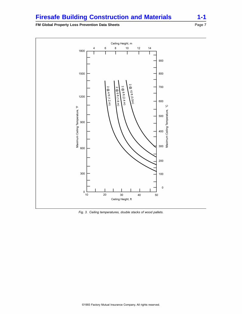
Fig. 3. Ceiling temperatures, double stacks of wood pallets.
Firesafe Building Construction and Materials 1-1FM Global Property Loss Prevention Data Sheets Page 7
©1993 Factory Mutual Insurance Company. All rights reserved.

Fig. 4. Ceiling temperatures, single stacks of wood pallets.
1-1 Firesafe Building Construction and MaterialsPage 8 FM Global Property Loss Prevention Data Sheets
©1993 Factory Mutual Insurance Company. All rights reserved.

Table 2. Typical ASTM E 84 Test Results on Combustibility of Selected Materials.Product Flame spread Smoke developed
Cementitious boardGypsum boardProtected metalAcoustical tileMineralWood fiberTreated wood fiberPainted glass fiberFir plywood:UntreatedTreatedFiberboardRed oak
015
35–40
10–1516020
10–15
13815300100
0080
0–101050
0–10
60055100
Fig. 5. Ceiling temperatures, flammable liquid pool fires.
Firesafe Building Construction and Materials 1-1FM Global Property Loss Prevention Data Sheets Page 9
©1993 Factory Mutual Insurance Company. All rights reserved.

Table 3. Heat-release Rates and Burning Duration of Selected ProductsBased on the FM Global Research Construction Material Calorimeter Test
Product
Heat-release rate
Duration ofburning, min
Metric-Heat-release rate
One min,Btu/ft2/min
PeakBtu/ft2/min
One min,MJ/m2/min
PeakMJ/m2/min
Cementitious board 0 0 0 0 0Gypsum board 73 73 2 829 829Protected metal (typical) 183 188 9 2,078 2,135Acoustical tile:MineralTreated wood fiber
125129
134134
68-1⁄2
1,4201,465
1,5221,522
Plywood, elm face, treated core 270 340 9 3,066 3,861Plywood, oak face, treated core 302 379 9 3,430 4,304Red oak 508 531 9 5,769 6,030
Where a non-plastic material has an ASTM E 84 flame spread rating of 25 or less, the hazard of the materialis low enough that automatic sprinkler protection is not needed for the material when used in a horizontalplane.
Omitting sprinklers based on ASTM E 84 test results alone does not apply to plastic materials, as the tunneltest does not give realistic results for such materials. In this test, plastics can release so much smoke thatflame is choked. Some foam and high-density plastics melt before a flame front is established. Plasticmaterials listed by FM Approvals for use on walls and ceilings/roofs are Approved (see Appendix A fordefinition) on the basis of the FM Approvals Corner Test. This test is described in Data Sheet 1-4.
3.1.3.2 FM Global Research Construction Material Calorimeter
The FM Global Research Construction Material Calorimeter is used to determine a material’s rate of heatrelease and duration of burning. These characteristics are significant for evaluating combustibility. Somematerials are tested for 10 minutes and the maximum acceptable one-minute heat-release rate for this testis 200 Btu/ft2/min (2270 MJ/m2/min).
Some typical test results are shown in Table 3. The test is not meant for unfaced foamed plastics, but isappropriate for foamed plastics having thermal barriers. It also is used by FM Approvals to Approve protectedmetal panels.
This apparatus also is used for a 30 minute test of roof deck assemblies including insulated steel deck andfire-retardant treated wood. Maximum acceptable heat release rates are as follows:
Table 4. Maximum Acceptable Heat Release Rates
Time Intervalmin
Max Fuel Contribution
Btu/ft2/min (kJ/m2/min)3 410 (4656)5 390 (4429)10 360 (4088)30 min 285 (3237)
Comparisons with large-scale tests show that a combustibility index based upon heat release rate is areasonable method to approve construction materials as Class 1 or limited combustibility.
1-1 Firesafe Building Construction and MaterialsPage 10 FM Global Property Loss Prevention Data Sheets
©1993 Factory Mutual Insurance Company. All rights reserved.

3.1.3.3 FM Global Research Susceptibility To Heat Damage Test
Heat alone can damage some materials. The FM Global Research Susceptibility to Heat Damage Testsubjects a sample of material to the following temperatures (no direct flame).
0 min—ambient5 min—425°F (218°C)10 min—475°F (246°C)15 min—500°F (260°C)20 min—500°F (260°C)
The sample is removed at the end of 20 min and examined. Curling, bowing, melting, dimensional change,decomposition, or discoloration must be negligible. Damage to the bottom side of the material should notexceed 1⁄8 in. (3 mm) in depth.
This test is generally conducted for insulations used in metal deck assemblies.
3.1.3.4 ASTM E 108 Test
The potential for firespread across the top surface of a roof may not be proportioned to the potential firespreadacross the bottom of the roof deck within the building. Roof surface fire spread is affected by gravel orconcrete paver block surfacing or other coatings, and the type of roof cover and insulation below it. A roofdeck could be fire resistive or of limited combustiblity, however, depending on the make-up of the above deckcomponents, there could be a potential for severe firespread across the top surface. Roof systems are firerated A, B or C according to ASTM E 108.
4.0 REFERENCES
4.1 FM Global
Data Sheet 1-0, Safeguards During Construction, Alteration and DemolitionData Sheet 1-3, High-Rise BuildingsData Sheet 1-4, Fire TestsData Sheet 1-5, Removal and Shipping of Roof Deck Samples for Calorimeter TestingData Sheet 1-12, CeilingsData Sheet 1-14, Construction SystemsData Sheet 1-17, Reflective Ceiling InsulationData Sheet 1-20, Protection Against Exterior Fire Exposure.Data Sheet 1-21, Fire Resistance of Building AssembliesData Sheet 1-22, Maximum Foreseeable LossData Sheet 1-23, Protection of Openings in Fire SubdivisionsData Sheet 1-24, Protection Against Liquid DamageData Sheet 1-28, Wind DesignData Sheet 1-29, Above Deck Roof ComponentsData Sheet 1-30, Repair of Wind Damaged Roof SystemsData Sheet 1-31, Metal Roof SystemsData Sheet 1-32, Existing PVC Roof CoversData Sheet 1-33, Safeguarding Torch-Applied Roof InsulationData Sheet 1-44, Damage-Limiting ConstructionData Sheet 1-57, Plastics in ConstructionData Sheet 1-60, Asphalt-Coated/Protected Metal BuildingsData Sheet 1-61, Fire-Retardant Treated WoodData Sheet 7-16, BarricadesData Sheet 7-29, Flammable Liquid Storage in Portable ContainersData Sheet 7-32, Flammable Liquid OperationsData Sheet 7-83, Drainage Systems for Flammable LiquidsData Sheet 9-1, Supervision of Property
Approval Guide, a publication of FM Approvals.
FM Global Hot Work Permit, Form 2630
Firesafe Building Construction and Materials 1-1FM Global Property Loss Prevention Data Sheets Page 11
©1993 Factory Mutual Insurance Company. All rights reserved.

4.2 NFPA Standards
National Fire Protection Association (NFPA)
NFPA 220, Types of Building Construction, 1999.
NFPA 259, Test Method for Potential Heat of Building Materials, 1998.
4.3 Others
American Society for Testing and Materials (ASTM)
ASTM E 84—91, Standard Test Method for Surface Burning Characteristics of Building Materials.
ASTM E 108—91, Standard Test Methods for Fire Tests of Roof Coverings.
ASTM E 119—95, Method for Fire Tests of Building Construction and Materials.
ASTM E 136—92, Test Method for Behavior of Materials in a Vertical Tube Furnace at 750°C.
ASTM E 605—77 (1982), Standard Test Methods for Thickness and Density of Sprayed Fire-ResistiveMaterial Applied to Structural Members.
ASTM E 736—86 (1991), Test Method for Cohesion/Adhesion of Sprayed Fire-Resistive Materials Appliedto Structural Members.
ASTM E 759—86 (1991), Test Method for Effect of Deflection of Sprayed Fire-Resistive Material Applied toStructural Members.
ASTM E 760—86 (1991), Test Method for Effect of Impact on Bonding of Sprayed Fire-Resistive MaterialApplied to Structural Members.
ASTM E 761—86 (1991), Test Method for Compressive Strength of Sprayed Fire-Resistive Material Appliedto Structural Members.
ASTM E 859—82, Test Method for Air Erosion of Sprayed Fire-Resistive Materials Applied to StructuralMembers.
Building Officials & Code Administrators (BOCA®)
National Building Code.
International Conference of Building Officials
Uniform Building Code.
National Research Council of Canada
National Building Code.
Southern Building Code Congress International (SBCCI)
Standard Building Code.
Similar standards available in countries outside the United States also may be utilized.
APPENDIX A GLOSSARY OF TERMS
A brief description of some terms are described below. For a more detailed description, examples andillustrations, see Appendix C.
Approved: references to ‘‘Approved’’ in this data sheet means the product and services have satisfied thecriteria for FM Approval. Refer to the Approval Guide for a complete listing of products and services that areFM Approved.
Boards-on-joist construction: consists of wood floor deck supported by closely spaced wood joists.
Fire-resistive construction: consists of materials that will withstand fire for the rated period without structuralfailure.
Limited-combustible construction: consists of materials that will not release sufficient fuel so as to allow aself-propagating fire.
1-1 Firesafe Building Construction and MaterialsPage 12 FM Global Property Loss Prevention Data Sheets
©1993 Factory Mutual Insurance Company. All rights reserved.

Noncombustible construction: consists of materials that will not allow for a self-propagating fire, contributea negligible amount of fuel, but are not necessarily fire resistive.
Plank-on-timber construction: also known as ‘‘heavy timber’’, ‘‘mill’’ or ‘‘slow-burning construction’’. It consistsof large wood members.
APPENDIX B DOCUMENT REVISION HISTORY
January 2011. Minor editorial changes were made. Deleted references to Data Sheet 1-19, Fire Walls,Subdivisions and Draft Curtains, that was made obsolete.
September 2007. Minor editorial changes were made.
January 2005. Deleted references to obsolete Data Sheet 8-0, General Storage Safeguards.
May 2003. Minor editorial changes were made for this revision.
May 2002. Minor changes were made to emphasize the use of noncombustible or limited combustiblematerials.
September 2000. This document has been reorganized to provide a consistent format. Only editorial andno major changes from May 1998 edition were made.
APPENDIX C CLASSIFICATION OF CONSTRUCTION
C.1 Major Types of Construction
Building framework often is categorized by relative fire hazard and resistance. These categories include:fire resistive, noncombustible or limited-combustible, plank-on timber, board-on-joists and wood frame.Building components of these types also can be combined in ways that result in construction types that donot fit neatly into any of the categories.
In the U.S., model building codes have a more specific definition of types of construction. Prior to the year2000, there were three model building codes in the U.S. They are the BOCA® National Building Code (NBC),the Standard Building Code (SBC) and the Uniform Building Code (UBC). Individual states generally useone of these as a model for their state codes, however, the most current model building code is not alwaysadopted immediately. Building codes have requirements for fire resistance ratings of all structural members,including walls, partitions, columns, floors and roofs. The National Fire Protection Association (NFPA)Standard 220, Types of Building Construction, contains similar criteria. Construction is broken down into fivegeneral categories.
Type I construction is noncombustible, and structural framework is protected (fire resistive).
Type II construction is noncombustible and is either protected to a lesser degree than Type I, or unprotected.
Type III construction may have protected or unprotected wood structural elements.
Type IV construction allows unprotected wood framing, such as heavy timber (heavy timber is Type IIIconstruction per SBC).
Type V construction allows any material acceptable to the code.
The SBC also specifies Type VI construction.
Factors that influence the type of construction required by the applicable building code include the numberof stories or building height, floor area and the occupancy.
Table 5 lists major structural components and the range of fire resistance requirements required by the fourU.S. codes or standards mentioned above. In some cases, there may be considerable differences betweenvarious codes. There also are many exceptions to the normal requirements, such as reductions in fireresistance ratings if sprinklers are provided, that are not noted in this table.
Firesafe Building Construction and Materials 1-1FM Global Property Loss Prevention Data Sheets Page 13
©1993 Factory Mutual Insurance Company. All rights reserved.
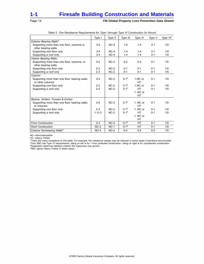
Table 5. Fire Resistance Requirements for Type I through Type VI Construction (In Hours)
Type I Type II Type III Type IV Type V Type VI2
Exterior Bearing Walls3
Supporting more than one floor, columns orother bearing wallsSupporting one floor onlySupporting a roof only
3-4
3-43-4
NC-4
NC-4NC-4
1-4
1-41-4
1-4
1-41-4
0-1
0-10-1
1/0
1/01/0
Interior Bearing WallsSupporting more than one floor, columns, orother bearing wallsSupporting one floor onlySupporting a roof only
3-4
2-32-3
NC-3
NC-2NC-2
0-2
0-10-1
0-2
0-10-1
0-1
0-10-1
1/0
1/01/0
ColumnSupporting more than one floor, bearing walls,or other columnsSupporting one floor onlySupporting a roof only
3-4
2-32-3
NC-3
NC-2NC-2
0-14
0-140-14
1,NC orHT
1,NC orHT
1, NC orHT
0-1
0-10-1
1/0
1/01/0
Beams, Girders, Trusses & ArchesSupporting more than one floor, bearing walls,or columnsSupporting one floor onlySupporting a roof only
3-4
2-31-1⁄2-3
NC-3
NC-2NC-2
0-14
0-140-14
1, NC orHT
1, NC orHT
1, NC orHT
0-1
0-10-1
1/0
1/01/0
Floor Construction 2-3 NC-2 0-14 HT 0-1 1/0Roof Construction NC-2 NC-1 0-14 HT 0-1 1/0Exterior Nonbearing Walls3 NC-4 NC-4 0-4 0-4 0-3 1/0
NC—NoncombustibleHT—Heavy Timber1There are many exceptions to this table. For example, fire resistance ratings may be reduced in some cases if sprinklers are provided.2Only SBC has Type VI requirements, rating on left is for 1 hour protected construction, rating on right is for unprotected construction.3Separation distances between exterior fire exposures may govern.4SBC allows Heavy Timber in these cases.
1-1 Firesafe Building Construction and MaterialsPage 14 FM Global Property Loss Prevention Data Sheets
©1993 Factory Mutual Insurance Company. All rights reserved.

C.2 Fire-Resistive Construction
Fire-resistive construction consists of materials that will withstand fire within the building, insulating asnecessary, for the rated period without structural failure.
Concrete (see Fig. 6) and protected steel-frame (see Fig. 7) construction are two types of fire-resistiveconstruction.
Concrete may be cast in place or precast. Concrete also may be prestressed by either pre-tensioning orpost-tensioning.
Pretensioned concrete is reinforced with high strength steel tendons, which are stretched between externalanchorages in the form prior to pouring the concrete. When the concrete reaches sufficient strength andhas bonded to the steel, the tensioning force is released.
Pretensioned concrete can be used for various structural purposes including wall, floor and roof construction.It is found in various shapes including double or single tees (usually 8 ft [2.4 m] wide), solid or hollow coreflat slabs and rectangular, L-shaped and inverted tee beams (see Figs. 8a. through e.). Columns and pilesalso can be prestressed. Because it must be transported, pre-tensioned concrete often is limited to 8 or 10ft (2.4 to 3.0 m) widths and 60 ft (18.3 m) lengths. With post-tensioned concrete, hollow conduits placedin the framework prevent the concrete from bonding to the tendons (see Fig. 9). After the concrete hashardened and reached sufficient strength, the tendons are then stretched by jacking against the concrete.Post-tensioning is most commonly used for beams, and floor slabs of multi-story buildings, however,pretensioning is used more often than post-tensioning.
Tilt-up concrete is often used when wider wall panels are utilized. The concrete is poured into formwork atthe job site and lifted into place after the concrete has reached sufficient strength. Panels are usually one baywide (20 ft [6.1 m] or more).
Fig. 6. Concrete frame construction.
Fig. 7. Concrete on protected steel construction.
Firesafe Building Construction and Materials 1-1FM Global Property Loss Prevention Data Sheets Page 15
©1993 Factory Mutual Insurance Company. All rights reserved.

With proper thickness and detailing, concrete cover over cables, and reinforcing bars etc., prestressed(pretensioned or post-tensioned) concrete can have the same fire resistance as monolithic concrete. In anycase, deterioration such as spalling of the concrete surface can expose reinforcing steel to a fire causingit to weaken and fail prematurely.
Fig. 8a. Double Tee.
Fig. 8b. Single Tee.
Fig. 8c. Hollow Core Flat Slab.
Fig. 8d. L-Shaped Beam.
1-1 Firesafe Building Construction and MaterialsPage 16 FM Global Property Loss Prevention Data Sheets
©1993 Factory Mutual Insurance Company. All rights reserved.

A two-way concrete slab is sometimes used in floor construction and has steel reinforcement placed in twodirections. The slab acts as the deck and secondary and primary framing. It may be either flat or ribbed intwo directions on its underside.
C.3 Protected Steel-Frame Construction
In protected steel-frame construction, the structural steel is provided with a fire resistant covering. Floorsand roofs are usually concrete or concrete fill on steel deck, with fireproofed supporting steel framework. Ifthe steel deck and concrete are integrated to form a composite roof system, or if additional insulation againstfire is needed, fireproofing of the deck may be applied as well. Sprayed fire-resistive materials applied tostructural members are particularly sensitive to application procedures and environment. A number of ASTMtest standards are applicable to such products and are listed in Section 4.0, of this data sheet. ASTM E 119fire testing is conducted in order to establish the needed fire resistance rating of the assembly. Other testsnoted in Section 4.0, are intended to test physical properties. ASTM E 759 (deflection), E 760 (impactresistance), E 761 (compressive strength) and E 859 (air erosion) are conducted in the laboratory and themanufacturer should certify that the materials meet these standards. ASTM E 605 (thickness and density), andE 736 (cohesion/adhesion) may be conducted in the laboratory or the field and are recommended as a checkof all new field installations. ASTM E 859 is particularly critical if the sprayed material is located in a returnair plenum (on the underside of a roof/floor deck in the space above a suspended ceiling). Areas adjacent toair inlets may be most vulnerable due to higher air velocities. If a sealer is applied over the fire-resistivematerial to prevent erosion, it should be a type that has been tested and listed with the fire-resistive materialto ensure that it does not detract from the noncombustibility or fire-resistance rating. An independentlaboratory should certify that these tests have been conducted and recommend repairs as needed. Similarstandards available in countries outside the U.S. may also be utilized.
Field testing of these sprayed applied products is necessary to ensure, among other things, that the amountof air-entraining material used in the formulation is not excessive. This could result in inadequate densityand impact resistance. Improper surface preparation can lead to inadequate adhesion and insufficientthickness also will result in protection that is less than recommended. After mechanical work has beencompleted, but before suspended ceilings are installed, visual examinations of fireproofing should be madeand bare spots/spalled areas should be repaired.
Fig. 8e. Inverted Tee Beam.
Fig. 9. Post-tensioned concrete beam.
Firesafe Building Construction and Materials 1-1FM Global Property Loss Prevention Data Sheets Page 17
©1993 Factory Mutual Insurance Company. All rights reserved.

Buildings constructed prior to 1940 may have the steel frame encased in concrete that is poured in forms,with decks of reinforced concrete (see Fig. 7). For added details on fire resistance, see Data Sheet 1-21, FireResistance of Building Assemblies. Listings for ‘‘Wall and Floor Penetration Fire Stops’’ can be found in theApproval Guide.
The basic function of automatic sprinkler piping is to reliably carry water under pressure to all sprinkler heads.When piping is supported by exposed steel, the structural system is a major factor affecting reliability.
With exposure to excessive atmospheric temperatures for even short periods of time, steel softens andweakens. At the same time, the steel is attempting to expand under the effect of the heat. If a degree ofrestraint to expansion is present, permanent distortion will result.
When a structural member is exposed to a fire, the interplay between softening, expansion, and restraintproduces a very complex behavior. To further complicate the behavior where there is direct exposure to hightemperatures, the top of horizontal members will be hotter that the bottom.
Tests have been run with loaded structural beams exposed to short term high temperatures of a nature thatwill result in borderline conditions for sprinkler lines. Typically, the structural beam will deflect upward initially.This is because the top of the member is expanding more than the bottom. At temperatures of a few hundreddegrees, the strength of the steel is reduced and deformations that offset the expansion occur. The steelmember settles to the starting position or slightly below.
With the approximate temperature-time relationship shown in Figure 10, deflections of structural memberssufficient to break fittings of sprinkler piping are probable. Exposures releasing great amounts of heat canproduce such ceiling temperatures if the proper sprinklers with water supplies sufficient to control the fireare not provided as outlined in the appropriate data sheet. Typical of such exposures are high-piledcombustible pallets, high-piled roll paper and many plastics. The appropriate data sheet also will indicatewhen exposed steel needs fireproofing in addition to adequate sprinklers and water supplies to provideprotection from specific exposures.
C.4 Noncombustible or Limited-Combustible Construction
The primary elements of noncombustible construction are noncombustible materials that fail to meet thefull requirements of fire-resistive construction. Generally, noncombustible construction has exposed steelsupporting members.
The principal fire-safety advantage of noncombustible or limited-combustible (Class 1) construction, ascompared with combustible construction, is their limited fire spread. It does not contribute significant fuel toa fire originating in the contents of the building or allow fire spread via the construction where there is onlya localized fire exposure. A serious disadvantage in several varieties is the inability to withstand firetemperatures for more than a few minutes without damage or structural failure.
Fig. 10. Exposure required to distort structural steel to the point where breakage of sprinkler pipe fittings will occur.
1-1 Firesafe Building Construction and MaterialsPage 18 FM Global Property Loss Prevention Data Sheets
©1993 Factory Mutual Insurance Company. All rights reserved.

Awide variety of roof materials is used in noncombustible construction. Examples are corrugated sheet metal,corrugated cementitious panels, precast concrete plank, concrete tile and poured gypsum. Class l insulatedsteel deck (see Fig. 11, and Data Sheet 1-28, Wind Design, and Section C.10 of this data sheet) andfire-retardant lumber (Data Sheet 1-61, Fire-Retardant Treated Wood) have limited combustibility, as definedby the FM Global Research Roof Deck Calorimeter Test.
Floors in buildings of noncombustible construction are either reinforced concrete or concrete on cellular orcorrugated metal panels.
Typical materials used for noncombustible walls are brick, concrete masonry units, corrugated metal, gypsumboard, corrugated cement. Approved insulated metal wall and ceiling/roof panels are of limited-combustibilityas defined by the FM Approvals Corner Test.
Cladding and framework for metal buildings are generally of noncombustible construction. These buildingsare usually constructed of exposed steel frame with steel or aluminum siding and roofing.
C.5 Combustible Materials in Noncombustible Construction
Some combustible materials are frequently used for siding, suspended ceilings, and interior finish in buildingsclassified as fire resistive or noncombustible. When these materials are of limited combustibility, such asClass 1 steel deck they do not challenge the integrity of the building. Even when combustible elements createa fire hazard requiring sprinkler protection, the classification of the construction is unchanged. For example,a reinforced concrete building with combustible, suspended, wood-fiber ceilings would still be called fireresistive, but automatic sprinkler protection would be needed to protect the ceiling, as it would be similarlyneeded to protect a combustible occupancy. Combustible ceilings are not recommended for high-risebuildings, regardless of the presence of automatic sprinklers.
Adding combustible components to otherwise noncombustible materials can result in a combustible,composite assembly. For example, mopping above deck roofing materials to the top surface of a corrugated,cementitious roof panel with hot asphalt may result in a Class 2 (combustible) roof assembly due to potentialburning of flammable vapors forced down through joints in the deck sections.
Fig. 11. Insulated steel deck on steel framing.(Note: above deck assembly should be of limited combustibility—see Section C.4)
Firesafe Building Construction and Materials 1-1FM Global Property Loss Prevention Data Sheets Page 19
©1993 Factory Mutual Insurance Company. All rights reserved.

C.6 Plank-On-Timber Construction
Plank-on-timber construction is also known as ‘‘heavy timber,’’ ‘‘mill’’ or ‘‘slow-burning’’ construction. It consistsof masonry walls with plank floors and roof on heavy timber supports (see Fig. 12). Floors of minimum 3in. (76 mm) plank with a hardwood overlay have an estimated fire endurance of 45 minutes available for firefighting before a fire ‘‘breakthrough’’ into the area above can be expected. The wide dimensions and spacingof beams, and the floor thickness are key factors that make this construction slow burning. Beams aregenerally 6 to 12 in. (150 to 300 mm) wide and spaced 6 to 12 ft (1.8 to 3.6 m) on center. Wood floor or roofframing with lesser dimensions are generally considered to be board-on-joist.
Heavy timber construction was used extensively prior to the invention of the concrete flat slab in 1906. Itwas implemented in multistory textile mills, one-story warehouses containing baled fibers and generalmanufacturing and storage occupancies. Little new construction is of this type.
C.7 Wood Joist Construction
Board-on-joist construction is a type of floor or roof construction in which boards are supported by closelyspaced wood joists. Floors are generally constructed of two-plies, (each 1⁄2 in. [13 mm] to 1 in. [25 mm] thick)of sheathing boards and have an estimated fire-resistance rating of about 10 to 15 minutes. Joists are usually1-1⁄2 in. (38 mm) in width, are usually 8 to 10 in. (200 to 250 mm) deep and spaced 12 or 16 in. (300 or 400mm) on center and usually span 12 to 14 ft (3.7 to 4.3 m). Plywood-on-joist construction is very similar exceptthat plywood is used in lieu of boards as decking. In heavy joist construction the joists are usually deeperand/or wider to accommodate heavier floor loads or longer spans.
Open-joist construction (see Fig. 13), with no interior sheathing or wood structural members, is frequentlyused where appearance is not important. The main disadvantages of open-joist construction, as comparedwith heavy timber, are the smaller size of the structural members, the greater combustible surface exposed
Fig. 12. Plank-on-timber construction.
1-1 Firesafe Building Construction and MaterialsPage 20 FM Global Property Loss Prevention Data Sheets
©1993 Factory Mutual Insurance Company. All rights reserved.

and the close spacing of supports which re-radiates additional heat. All contribute to the rapid spread of fire.However, with complete automatic sprinkler protection and no other unfavorable factors, this type ofconstruction has reasonable loss experience.
In hollow-joist construction, the underside of the joist is sheathed. It is less desirable than open-joistconstruction because of the concealed spaces through which fire can spread, shielded from sprinklers.Adequate firestopping is essential. For further details, refer to Data Sheet 1-12, Ceilings.
C.8 Wood Frame Construction
If floors and walls are of board-on-joist or wood truss construction and the structural members of the wallsare wood, the construction is called wood frame (see Fig. 14). Sheathing may be noncombustible such asgypsum board, brick, or metal. The combination of rapid burning floors and combustible wall framing makesthis construction framework type more susceptible to fire spread. Wood framing is not desirable in multi-storybuildings.
Fig. 13. Open boards on joists.
Fig. 14. Wood frame construction.
Firesafe Building Construction and Materials 1-1FM Global Property Loss Prevention Data Sheets Page 21
©1993 Factory Mutual Insurance Company. All rights reserved.

C.9 Plywood Diaphragm Roof
Another type of wood roof construction that is popular in some areas is the plywood diaphragm roof (seeFig. 15). The roof system acts as a thin, deep beam that resists lateral loads, such as wind or earthquake,in the place of the member.
In this type of construction, a plywood deck is supported on 2×4 in. (51×102 mm) sub-purlins spacedapproximately 2 ft (0.6 m) on center (o.c.). The sub-purlins butt into and are supported by 4 in.×12–24 in.(102 mm × 305–610 mm) purlins spaced approximately 8 ft (2.4 m) o.c. These, in turn, butt into and aresupported by 7 in.×24–40 in. (178 mm×610–10200 mm) glue-laminated beams. The ‘‘glu-lam’’ beams areusually spaced 20 to 24 ft (6 to 7 m) apart. Member sizes and spacing may vary somewhat in individualinstallations. In some installations, the glu-lam beams run in both directions. In some plywood deckconstructions, the sub-purlins and/or purlins do not butt into their respective supporting members but arecontinuous over them. Because of the spacing of the sub-purlins, this is considered equivalent to boards-on-joist construction from a fire standpoint.
Reflective ceiling insulation is most commonly encountered with this type of construction and can in somecases be a fire hazard. A detailed description and recommendations for reflective ceiling insulation can befound in Data Sheet 1-17, Reflective Ceiling Insulation.
C.10 Other Construction Types
Some construction types do not fit neatly into the above categories, but still represent a sizeable portion ofmodern construction types. These include plank-on-steel, asphalt-coated metal, protected metal and Class 2insulated metal deck.
Plank-on-steel construction consists of 4 to 8 in. (102 to 203 mm) thick wood plank on steel or wood beamsattached to steel girders. Plank-on-steel construction is combustible and is subject to early collapse in anuncontrolled fire.
Asphalt-Coated Metal (ACM). ACM buildings are steel-frame buildings having metal siding and/or roofingthat has been coated on both sides with asphalt. The coating increases the fire hazard substantially. Buildingsof this type are discussed in detail in Data Sheet 1-60, Asphalt-Coated/Protected Metal Buildings.
Protected Metal (PM). PM buildings are similar to ACM buildings except that roofing and siding panels haveconsiderably less asphaltic coating or they are coated with paint at 5 mils (0.13 mm) or less, or are coatedwith zinc or zinc-aluminum alloys (galvanized). This also is discussed in Data Sheet 1-60.
Fig. 15. Typical plywood diaphragm roof deck (not to scale).
1-1 Firesafe Building Construction and MaterialsPage 22 FM Global Property Loss Prevention Data Sheets
©1993 Factory Mutual Insurance Company. All rights reserved.

Class 2 Insulated Metal Roof Decks. In the types of construction described above, combustibility of the roofis generally determined by the physical characteristics of the roof deck and supporting structure. Fire testsand experience show that critical quantities of some combustible above-deck components (e.g., the insulation,adhesive, vapor retarder and roof covering) will result in a Class 2 steel deck. If exposed to fire even locallyand not protected, this could allow a spreading interior fire due to the above-deck construction alone. Priorto the 1980s, hot asphalt was often mopped to the deck to secure above deck components. This generallyresulted in a Class 2 assembly.
Insulated metal deck usually consists of a water-resistant covering on insulation, with or without a vaporretarder (barrier), which is secured to a metal roof deck. The water-resistant covering generally consists ofseveral plies of felt, or a single-ply membrane, either smooth or with a gravel surface (see Fig. 16). Foradditional information on above deck roof components, refer to Data Sheet 1-28, Wind Design ; Data Sheet1-29, Above-Deck Roof Components; Data Sheet 1-30, Repair of Wind Damaged Roof Systems; Data Sheet1-31, Metal Roof Systems; Data Sheet 1-32, Existing PVC Roof Covers, and the Approval Guide.
An assembly should be considered Class 2 if the above deck components are not Approved in specificcombination, unless a calorimeter test is conducted to prove otherwise (see Data Sheet 1-5, Removal andShipping of Roof Deck Samples for Calorimeter Testing).
In some cases, variations from the Approval Guide or Data Sheet 1-28 can affect wind resistance, and mayor may not affect the fire hazard. A first layer of insulation that is thinner than Approved may adversely affectwind resistance, or may increase the fire hazard and result in a Class 2 roof. (Note: manufacturers alsospecify minimum insulation board thickness for structural strength to span rib openings in the steel deck. Seethe Approval Guide and Data Sheet 1-28.) The use of aluminum deck instead of steel generally results ina Class 2 metal deck because of the relatively low melting temperature of aluminum.
Fig. 16. Typical Class 2 insulated metal roof deck construction with vapor barrier.
Firesafe Building Construction and Materials 1-1FM Global Property Loss Prevention Data Sheets Page 23
©1993 Factory Mutual Insurance Company. All rights reserved.

Steel deck has a melting temperature of about 2650°F (1450°C), and consequently does not melt in eithera typical fire or in a calorimeter test. The contribution to fire spread due to fire exposure on the underside ofthe deck is limited to flammable vapors forced through joints in the deck. Aluminum deck has a meltingtemperature of about 1050°F (565°C) and, consequently would melt in a typical fire or in the calorimeter test.This would directly expose most of the underside of the combustible above deck components in the flameimpingement area. That would greatly increase the fuel contribution rate of the above deck components andresult in a Class 2 roof.
Sprinkler protection is generally recommended below Class 2 roofs, however, for exceptions refer to DataSheet 1-12. An Approved undercoating applied to the underside of the deck is an acceptable alternative tosprinklers if the occupancy is noncombustible.
Class 1 Insulated Metal Roof Decks. A roof deck calorimeter test is conducted to determine the heat releaserates of the above deck components. Assemblies that have rates that do not exceed the acceptable criteriawill have a limited fire spread and are categorized as Class l (limited combustible) insulated steel deck.Assemblies that qualify for Class 1 are listed in the Approval Guide and described in Data Sheet 1-29 anddo not, by themselves, necessitate sprinkler protection.
Since the early 1980’s, insulated steel deck has generally been constructed using mechanical fasteners tosecure insulation to the deck. In this case the limited combustibility of the insulation, and its ability to act asa thermal barrier to limit fuel contribution from other components above, is necessary to maintain a Class1 fire rating. Prior to the 1980’s, adhesives were often used to secure the insulation to the deck (see Fig. 17)and it was necessary to limit the quantities of adhesives as well in order to maintain a Class 1 fire rating.Such construction is no longer recommended due to adverse wind loss experience (see Data Sheet 1-29).
Insulated metal decks are not used for floor construction. Consequently, when metal deck is noted belowan upper floor it is generally being used as a form deck (for concrete) which will remain in place.
Stucco on wood or metal lath is sometimes used for wall construction. This should not be confused withEIFS noted in Section C.5.
Fig. 17. ‘‘Old Style’’ Class 1 insulated steel deck roof using limited quantities (ribbons) ofadhesive to secure insulation and vapor barrier.
1-1 Firesafe Building Construction and MaterialsPage 24 FM Global Property Loss Prevention Data Sheets
©1993 Factory Mutual Insurance Company. All rights reserved.