fm10 - canford - professional audio, video and broadcast ... exciter/transmitter technical manual...
TRANSCRIPT

FM10
FM EXCITER/TRANSMITTER
TECHNICAL MANUAL

Page 2
CONTENTS 1 Introduction 2 Safety, Electrical hazard 3 Safety, Toxic hazard 4 Unpacking 5 Controls and Connectors 6 Installation 7 Alignment 8 Specifications 19 How to contact Eddystone Broadcast Limited 10 Technical Section Contents 11 Declaration of conformity No part of this manual may be reproduced or transmitted in any form or by any means, electronic or mechanical, including photocopying, recording or information storage and retrieval systems, for any purpose other than the purchaser's personal use, without the express written permission of sbs. Information in this document is subject to change without notice and does not represent a commitment on the part of Eddystone Broadcast Limited. Eddystone Broadcast Limited shall not be liable for any direct, indirect, consequential or incidental damages as a result of the use or misuse of this equipment, handbook or any related materials.

Page 3
1 Introduction ────────────────────────────────── The Eddystone Broadcast Limited FM10 has been designed for groups looking for low power FM transmission equipment. It can include a high quality deviation limiter and stereo encoder. With the addition of a low-cost aerial it is all that is needed to get on air. Because of the broadband design of the unit, no tuning is required. Frequency setting is by means of internal, direct reading dial up switches. Output is automatically muted during lock-up time. The stereo version is available with its own high quality deviation limiter and coder. This can be offered as an upgrade for the mono FM10. The unit will operate into any SWR without damage, with an effective VSWR protection circuit which reduces the output power if necessary to protect the amplifier.
Page 4
2 Safety, Electrical hazard ────────────────────────────────── This unit contains high voltages which could be fatal. YOU MUST ALWAYS ISOLATE THE UNIT FROM THE MAINS SUPPLY BY COMPLETELY DISCONNECTING IT BEFORE ATTEMPTING TO OPEN THE CASE. THIS EQUIPMENT MUST BE EARTHED. Do not expose this equipment to rain or any other source of moisture. In common with all mains operated equipment, only suitably trained competent personnel should attempt to adjust, modify or repair this equipment or operate it with the cover removed. In case of query please contact your local agent or Eddystone Broadcast Limited. Any unauthorised adjustment, modification or repair of this equipment may invalidate any warranty and/or safety approvals that apply. Please read all of this manual and familiarise yourself with the controls before attempting to use this equipment. To ensure safety, it is the responsibility of the user to install and operate this equipment in a manner that is within the manufacturers specifications.
Page 5
3 Safety, Toxic hazard ────────────────────────────────── This equipment includes devices which contain Beryllium Oxide which is a highly toxic substance. Inhalation or ingestion of even tiny particles could be injurious to health or even FATAL! Extreme care must be exercised when replacing and discarding components which may contain Beryllium Oxide. If any such device is physically damaged you should seek expert advice, e.g. by contacting the device's manufacturers. All such devices must be disposed of in accordance with local regulations. In the UK your local council will have a toxic waste disposal department who will be able to advise you. Elsewhere you should contact the responsible authorities. NEVER DISPOSE OF A DEVICE CONTAINING BERYLLIUM OXIDE WITH GENERAL WASTE.
Page 6
4 Unpacking ────────────────────────────────── This package should contain:- 1x FM10 Series broadcast exciter/transmitter 1x IEC Mains lead 1x FM10 series manual If any items are missing or damaged please inform your supplier immediately. Initial Checks Ensure that the FM10 has been set to the correct mains/line voltage for your country. The standard version is set to 230V.
Page 7
5 Controls and Connectors ────────────────────────────────── Front Panel: POWER Mains power is applied. LIMIT The audio input level is high enough for the limiter to reduce its
level (where fitted). Rear Panel: Audio input Unbalanced on female BNC connector without internal limiter or
balanced on female XLR connector with optional limiter (pin 2 hot, 3 cold and 1 ground).
EXT MPX Loop Multiplex output (unbuffered) on BNC connector, switchable
multiplex input on BNC connector. If switch is in ON position, the multiplex is disconnected internally. If switch is in OFF position, the external multiplex input is disabled and the multiplex signal is connected internally.
Monitor 25 way female D-type.
Pin 1 Power supply OK Pin 2 Forward power OK Pin 4 Mute RF output Pin 5 - 24 reserved. Pin 25 Ground
The power supply OK and forward power OK outputs are open
collector and are normally low/ON in the normal condition. The Mute input should be grounded to mute the output. This connector is not normally fitted on cable distribution versions.
O/P Monitor Monitor of RF output (approx. -40dBc). This output should not be
used to measure harmonic/spurious levels. RF Out 50Ω N type female connector. Power Multi turn power control. Mains Filtered IEC male connector with T1A fuse in pull out drawer.
Page 8
6 Installation ────────────────────────────────── The FM10 is normally supplied ready aligned, therefore installation should be straight forward. Before installation please read the section of this manual about Electrical safety. RF leads should be made from high quality low loss cable and connectors of the correct impedance, using the manufacturers recommended termination techniques. Since connectors are a source of unreliability in any system, the number of terminations in any RF lead should be kept to a minimum. All other cables for audio and control signals should be high quality screened types. For XLR connectors, the screen should be connected to the connector body.
Page 9
7 Alignment ────────────────────────────────── The FM10 is usually supplied ready aligned and therefore the following steps should not normally be necessary:-
7.1 Frequency setting 7.2 Output power/level 7.3 Forward power alarm 7.4 Modulator input level 7.5 DLM3 PCB 7.6 LimX PCB
When an automatic change over system is in use (such as the ACU3) this should be disconnected/overridden such that the FM10 operates continuously during the set-up procedure. 7.1 FREQUENCY SETTING Setting the frequency is a simple operation. Direct reading dials are located on the PLL7 PCB. For example, to set a frequency of 107.30MHz, set the 10MHz dial to 0, the 1MHz dial to 7, the 100kHz dial to 3 and the 12.5kHz dial to 0. For 98.35 set 10MHz dial to 9, the 1MHz dial to 8, the 100kHz dial to 3 and the 12.5kHz dial to 4 (4 x 12.5kHz = 50kHz). Whilst the Phase Locked Loop is Locking up the modulator output is muted (indicated by the PLL LOCK LED on the PLL7 PCB). When the FM10 is either powered up or the frequency changed, it will normally take about 5 seconds for the PLL to lock up. However if the frequency is changed from a high one to one at the bottom of the band, with the unit in operation, it can take up to 10 seconds for the PLL to attain lock.

Page 10
7.2 OUTPUT POWER/LEVEL A small trimmer tool or precision screwdriver will be required to adjust the output power. The control is located on the rear panel. The output power should be set using an accurate power meter connected to the RF output which in turn should be connected to an adequately rated dummy load. If a dummy load is not available then the FM10 could be set up connected to the aerial. In this case the Output Power control should be set to minimum (anti-clockwise) before powering up the FM10. 7.3 FORWARD POWER ALARM This setting defines the point at which a forward power fault is indicated at the Control/Monitor socket (for telemetry and/or operation of an automatic change over system). This is not adjustable on the FM10. It is pre-set to about 3W. 7.4 MODULATOR INPUT LEVEL The setting of the modulator AUDIO LEVEL control (on the PLL7 PCB) will depend on the version supplied. For the FM10/M please read the section below headed DLM3 PCB and for the FM10/S please read the section headed LimX PCB. An accurate deviation meter will be required, which should be connected to the rear panel RF monitor socket (or output on the cable distribution version). Mono/MPX version (no limiter or stereo encoder) The FM10 is normally supplied with the modulator input level set so that an input level of +8dBu over the range 5Hz to 100kHz (without pre-emphasis) gives a deviation of 75kHz. If a different level is required then it will be necessary to reset the AUDIO LEVEL control on the PLL7 board. Apply a 400Hz sine wave at the level required for maximum deviation (normally 75kHz). Adjust the AUDIO LEVEL control to give the required deviation. Full details of the alignment procedure are available on request from Eddystone Broadcast.
Page 11
7.5 DLM3 PCB 1 FET BIAS Connect an audio input at 400Hz to the Mono input that is below the limit threshold, for example -20dBu. Turn R33 fully anti clockwise. Connect an oscilloscope or level meter to U3 pin 7. Turn R33 slowly clockwise until the level is reduced by 0.1dB. The level will vary whilst R33 is turned. 2 MODULATOR INPUT LEVEL Connect an audio input at 400Hz to the audio input such that the front panel limit LED is fully ON. LINK TP1 on the DLM3 PCB to ground. This disables the limiter, leaving the clipper active. Adjust the AUDIO LEVEL control on the PLL7 PCB to give 75kHz minus your desired Guard-band of deviation. A typical value would be between 55 and 65 kHz. Disconnect the ground link from TP1. 3 INPUT LEVEL Connect an audio oscillator to the audio input. Set its output to 400Hz and the output level to the desired limit threshold. Turn R19 fully anti clockwise. Connect an oscilloscope to the MPX OUTPUT connector. Turn R19 clockwise and observe that the peak level shown on the oscilloscope increases. Stop adjusting R19 at the point where the peak level stops increasing.
Page 12
7.6 LimX PCB 1 FET BIAS Connect an audio input at 400Hz to the LEFT and RIGHT or mono inputs that is below the limit threshold, for example -20dBu. Turn R40 and R31fully anti clockwise. Connect an oscilloscope or level meter to U7 pin 7. Turn R31 slowly clockwise until the level is reduced by 0.1dB. The level will vary whilst R31 is turned. Connect the oscilloscope/level meter to U6 pin 7. Turn R40 slowly clockwise until the level is reduced by 0.1dB. The level will vary whilst R40 is turned. 2 MODULATOR INPUT LEVEL Connect an audio oscillator, level +8dBu at 1kHz to the MPX IN socket and turn the EXT MPX LOOP switch on (right position). Using a deviation meter, adjust the AUDIO LEVEL control on the PLL7 PCB to give 75kHz deviation. Return the EXT MPX LOOP switch to the OFF position (left). 3 LimX OUTPUT LEVEL Connect an audio input at 400Hz to the LEFT and RIGHT audio inputs such that the front panel limit LED is fully ON. LINK TP1 on the LimX PCB to ground. This disables the limiters, leaving the clippers active. Switch the pilot off. Adjust R1 to give 75kHz minus 6.75kHz minus your desired Guard-band deviation. A typical value would be between 50 and 60 kHz. Disconnect the ground link from TP1. 4 INPUT LEVEL Switch the pilot off. Connect an audio oscillator to the left and right inputs. Set its output to 400Hz and the output level to the desired limit threshold. Turn R15 and R3 fully anti clockwise. Connect an oscilloscope to the MPX OUTPUT connector. Turn R15 clockwise and observe that the peak level shown on the oscilloscope increases. Stop adjusting R3 at the point where the peak level stops increasing. Now adjust R15 clockwise until the waveform is a pure sine wave. 5 PILOT LEVEL Disconnect the audio input. Switch the pilot on. Adjust R86 to give a deviation of 6.75kHz. In any of the above cases, if an RDS/SCA unit is to be connected, the output level of it may need re-calibration.

Page 13
8 Specifications ────────────────────────────────── Frequency range 87.5 to 108 MHz in 50kHz steps Frequency stability <± 200Hz Power output 1 - 10W Harmonic & spurious output < -76dBc AM noise < -50 wrt 100% Nominal input level 0dBu or +8dBu (adjustable) Input Electronically balanced with limiter or unbalanced Input impedance 20 kΩ CMRR 54dB (typ.) Pre-emphasis 50uS AF response (with pre-emphasis) <±0.5dB (50Hz-15kHz) THD < 0.15% at 75kHz Power supply 230VAC ±10% Power consumption < 40VA Dimensions 1Ux260mm

Page 14
9 How to contact Eddystone Broadcast Limited ────────────────────────────────── For all enquiries write to:- Eddystone Broadcast Limited 26 Arden Road Arden Forest Industrial Estate Alcester Warwickshire B49 6EP Or telephone 01789 762278 within the UK, +44 1789 762278 from outside the UK. Or fax 01789 766033 within the UK, +44 1789 766033 from outside the UK. Or email [email protected] Alternatively visit our web site: http://www.eddystone-broadcast.com/

Page 15
10 Technical Section Contents ────────────────────────────────── 10.1 PLL7 Modulator PCB 10.2 PSU15 Power Supply PCB 10.3 DLM3 Limiter PCB (FM10/M only) 10.4 LimX Stereo coder (FM10/S only) 10.5 FM10-PA 10W Power amplifier

Page 16
10.1 PLL7 ────────────────────────────────── The frequency determining element is formed by coil L1 and varicap diodes VD1 and VD2, together with capacitors C17- C20. These components are used as part of a cascode oscillator whose output is then buffered by transistor T3. The RF output from T3 is impedance matched to the base of transistor T5 by RFT1, a 4 to 1 matching transformer. The high power output from T5 is impedance matched by coils L2 and L3 and associated capacitors to the 50 ohm output socket CON2. These components also provide harmonic filtering. The PLL circuit is primarily IC2 which is a serially programmable PLL chip. The microcontroller IC3 reads the dial switches at switch on and outputs a serial code to the PLL chip in a format that determines the output frequency that the PLL will try and lock the transmitter to. The PLL chip outputs control pulses to the loop filter built around op amp IC4. The loop filter takes the sharp pulses from the PLL chip and converts them into a smoothed signal ready to apply to the frequency determining components, varicap diodes VD1 and VD2. IC1 is an analogue switch that shorts out two of the resistors in the loop filter which enables the transmitter to get on frequency faster. When the oscillator is on frequency the Analogue switch switches out which greatly improves the audio response of the transmitter. The microcontroller IC3 determines when to switch the analogue switch in and out by reading the lock detect signals from the PLL chip. The microcontroller can also use this information to switch off transistor T3 with open collector configured T4 which mutes the RF output when the transmitter is out of lock. LED1 provides visual indication of the PLL locked condition. The master clock oscillator (OSC1) determines the accuracy of the output frequency. It is a high stability temperature compensated crystal oscillator (TCXO). The frequency can be trimmed if required by adjusting the small trimmer located beneath a hole in the oscillator module. Audio is fed into the modulation input connector CON2. From here the signal passes to variable resistor VR2 where modulation levels can be set, it is then passed via R29 to the varicap diodes.
Page 17

Page 18
10.2 PSU15 ──────────────────────────────────

Page 19
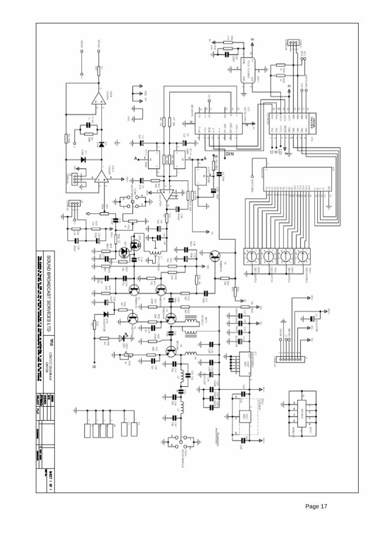
10.3 DLM3 ──────────────────────────────────
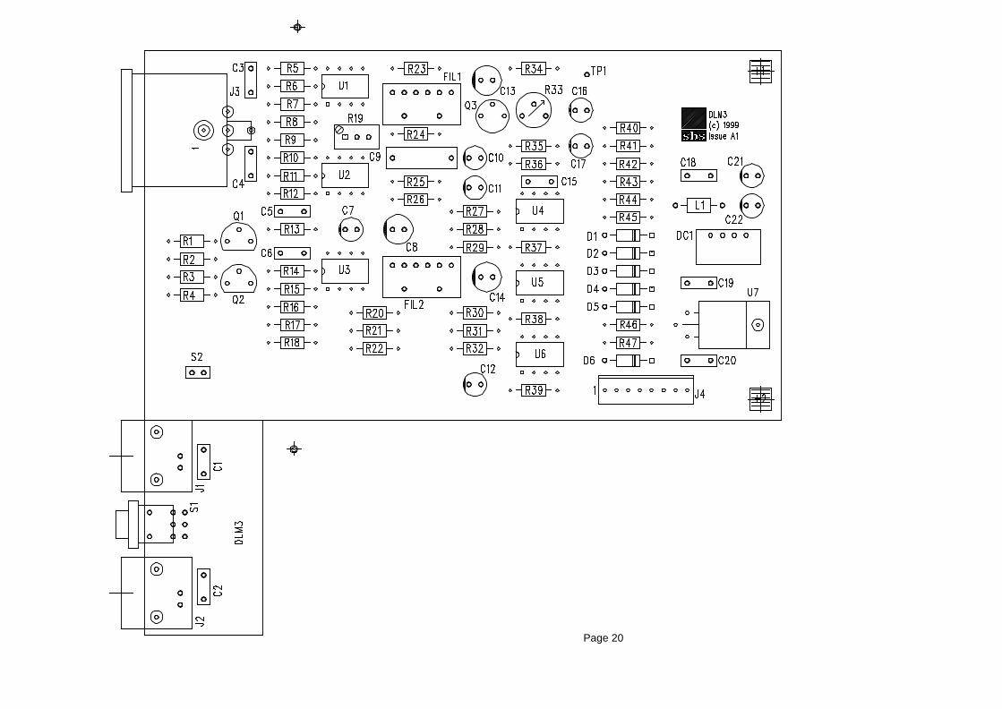
Page 20

Page 21
10.4 LimX ──────────────────────────────────

Page 22

Page 23
10.5 FM10-PA ──────────────────────────────────
Page 24
11 Declaration of conformity ────────────────────────────────── Name of Manufacturer: sbs Product: FM10 FM Exciter Declaration: The product described above compiles with the requirements of the Low Voltage Directive (73/23/EEC) and the protection requirements of the EMC Directive (89/336/EEC) issued by the Commission of the European Community. Compliance with these directives implies conformity to the following European Standards:
EN 60065:1998 Safety requirements for mains operated electronic and related apparatus for household and similar general use
EN 50081-2:1994 Electromagnetic compatibility. Generic emission standard.
Industrial environment
EN 50082-2:1995 Electromagnetic compatibility. Generic immunity standard. Industrial environment
Additionally, the product described above complies with all relevant parts of the following standards:
ETS 300 384:1995 Radio broadcasting systems; Very High Frequency (VHF), frequency modulated, sound broadcasting transmitters
Signed:
On file
Date of Issue:
16. 05. 2001
for and on behalf of sbs, UK
Pyers Easton CEO