fm 11-32 combat net radio operations 11-32 15-oct-90 aclu.pdf · fm 11-32 combat net radio...
TRANSCRIPT

FM 11-32
COMBAT NET RADIO OPERATIONS
FM 11-32 Table of Contents Page 1 of 3
FM 11-32
Field Manual Headquarters No 11-32 Department of the Army
Washington, DC, 15 October 1990
Editor's Note: Distribution Restriction changed to "Approved for public release; distribution is unlimited" per HQ TRADOC (ATCD-K) Memorandum, 18 Jul 1991, Doctrinal Publications with Incorrect Distribution Restrictions, and HQ TRADOC Foreign Disclosure Office e-mail, 10 Jan 2001, Documents Approved for Public Release.
Table of Contents
Preface
Chapter 1 - Combat Net Radio (CNR) Deployment
1 - 1. New Equipment
1-2. The CNR Network
1-3. Doctrinal Networks
1-4. Corps and Division
Chapter 2 - Special Applications for CNR Deployment
2-1. Special Forces, Ranger, and Long-Range Surveillance Units (LRSUs)
2-2. Joint/Combined Operations
http://atiam.train.army.mil/portal/atia/adlsc/view/public/296856-1/fm/11-32/toc.htm 2/25/2005
DODDOA 026079

FM 11-32 Table of Contents Page 2 of 3
Chapter 3 - SINCGARS
3-1. System Description
3-2. Components
3-3. Ancillary Equipment
Chapter 4 - FH Networks
4-1. FH Variables
4-2. Unit Standing Operating Procedure (SOP) Considerations
Chapter 5 - SINCGARS Planning
5-1. Network Requirements
5-2. Data Nets
5-3. Secure Devices
5-4. VHF-FM Retransmission Stations
5-5. NRI Systems
Chapter 6 - IH FR
6-1. System Description
6-2. Components
6-3. System Configurations
6-4. Ancillary and Secure Equipment
Chapter 7 - CNR Frequency Management
7-1. Overview
7-2. Frequency Allocations
7-3. TSK Management
7-4. Time Management
7-5. BSM Responsibilities
7-6. BSO Responsibilities
http://atiam.train.army.mil/portal/atia/adlsc/view/public/296856- I /fm/11-32/toc.htm
2/25/2005
DODDOA 026080

FM 11 -32 Table of Contents Page 3 of 3
Chapter 8 - BECS
8-1. System Description
8-2. Components and Capabilities
8-3. Software Management
Chapter 9 - Special Siting Considerations
9-1. Overview
9-2. Cositc Interference
9-3. Symptoms and Solutions
Chapter 10 - TACSAT Single-Channel System
10-1. System Description
10-2. Architecture
10-3. Employment
10-4. System Configuration
10-5. Planning Considerations
10-6. Anit,jamming and ECCM Techniques
10-7. Future TACSAT Single-Channel Systems
Appendix - Suggested SOP for SINCGARS
Glossary
References
Authorization Letter
Unless otherwise stated, whenever the masculine gender is used, both men and women are included.
http://atiam.train.army.millportaliatia/adlsc/view/public/296856-1/fm/11-32/toc.htm
2/25/2005
DODDOA 026081

FM 11-32 Preface Page 1 of I
Preface
Purpose and Scope
This manual serves as a reference document for combat net radio (CNR) systems. It does not replace field manuals governing combat, combat support (CS), or combat service support (CSS) unit tactical deployment or technical manuals on equipment use. This manual provides guidance for using single-channel radios on the modern battlefield. It addresses planning and operating techniques and considerations to ensure full interoperability of new generation frequency-hopping (FH) radios with the previous generation and with allied nation single-channel radios. It also addresses FH radios in the single-channel mode.
This manual describes new systems being fielded and provides specific doctrinal uses for each of those systems. This manual describes equipment setups and planning steps for CNR systems. It also suggests items to consider for battalion and brigade standing operating procedures (SOPs).
This manual is intended for operators, supervisors, and planners to provide a common reference for new CNR radios. It gives operators and supervisors basic guidance and operating instructions. It also gives the system planner the necessary steps for network planning, interoperability considerations, and equipment capabilities.
User Information
The proponent of this publication is HQ TRADOC. Your comments on this publication are encouraged. Submit changes for improving this publication on DA Form 2028 (Recommended Changes to Publications and Blank Forms) and key them to pages and lines of text to which they apply. If DA Form 2028 is not available, a letter is acceptable. Provide reasons for your comments to ensure complete understanding and proper evaluation. Forward your comments to Commander, United States Army Signal Center and Fort Gordon, ATTN: ATZH-DTL, Fort Gordon, Georgia 30905-5075.
http://atiam.train.army.mil/portal/atia/adIsc/view/public/296856-1/fm/11-32/Prefhtm 2/25/2005
DODDOA 026082

FM 11-32 Chptr 1 Combat Net Radio (CNR) Deployment Page 1 of 12
Chapter 1
Combat Net Radio (CNR) Deployment
1-1. New Equipment
a. Modern semiconductor technology has made high-speed signal prOcessing part of everyday life and has enhanced communications systems capabilities. Adding electronic counter-countermeasures
(ECCM) modules and devices makes radios and command and control (C 2) facilities more survivable. Frequency hopping (FH) is a spread-spectrum radio technique. It degrades enemy forces' abilities to find, monitor, or destroy friendly systems.
b. Single-channel radios are being upgraded or replaced. This provides the maneuver force commander
with a reliable multifaceted C 2 communications system. The combination of high frequency (HF), very high frequency (VHF), and ultra high frequency (UHF) radios gives commanders redundant, but different, means to control their forces. Each system takes advantage of a different transmission path increasing the probability that at least one communications system will work at any given time.
c. Joining active electronic and passive ECCM techniques with multiple radio sets in the C .- system provides effective communications to control ground and airborne forces. However, the increase in complexity and number of different radio types also increases the predeployment planning necessary to ensure completely operational communications networks.
1-2. The CNR Network
a. The CNR network is designed around three separate radio systems. Each system has different capabilities and transmission characteristics. The three systems are--
• Improved high frequency radio (IHFR). • Single-Channel Ground and Airborne Radio System (SINCGARS). • Single-channel tactical satellite (TACSAT).
The CNR network's primary role is voice transmission for C 2 . The CNR network assumes a secondary role for data transmission when requirements exceed the Army Data Distribution System (ADDS) or
Mobile Subscriber Equipment (MSE) capabilities. Voice C 2 information maintains priority over data in most networks. The exception is using SINCGARS with the Tactical Fire Direction System (TACFIRE)
or Advanced Field Artillery Tactical Data System (AFATDS). Current demands on voice C 2 networks require a large amount of operational time dedicated to voice. This leaves little time for data sharing.
(1) The IHFR will selectively replace the current HF manpack and vehicular radios. It will use ground and skywave propagation paths for short- and medium-range communications. FM 24-18 covers radio wave propagation. IHFR gives the tactical commander alternate means of passing
voice and data communications. IHFR has a dual role with voice C 2 taking precedence over data transmission. Passing data requires an interface device called a modem. The high-power version is
used for voice networks that pass highly perishable C 2 information or for medium- to long-range communications (50 to 300 kilometers (31 to 186 miles)). Brigade and battalion level units primarily use the low- power version (0 to 50 kilometers (0 to 31 miles)). All IHFR versions are
http://atiam.train.army.miliportal/atiaiadIsciview/public/296856-1/fm/11-32/Chl.htm 2/25/2005
DODDOA 026083

FM 11-32 Chptr 1 Combat Net Radio (CNR) Deployment Page 2 of 12
user-owned and -operated.
(2) SINCGARS is replacing all AN/PRC-77 manpack and AN/VRC-12 series vehicular mounted VHF and airborne VHF frequency modulated (FM) radios. SINCGARS accepts either digital or analog inputs and imposes the signal onto an FH output signal. In FH, the input changes frequency about 100 times per second over portions of the tactical VHF range from 30 to 88 MHz. This hinders threat intercept and jamming units from locating or disrupting friendly communications. SINCGARS is the primary means for short-range (less than 35 kilometers (22
miles)) secure voice C 2 below division level. It is also the secondary means for combat support (CS) and combat service support (CSS) units throughout the corps. SINCGARS is user-owned and -operated like the current VHF-FM radios. SINCGARS can provide access to the area common-user (ACU) network through the Net Radio Interface (NRI) System, or its range can be increased by retransmission. Data and facsimile transmission capabilities are available to tactical commanders through simple connections with various data terminal equipment (DTE). Until the ADDS fielding is complete, SINCGARS will, on a limited basis, fulfill the data transmission requirements. However, avoid this when possible because voice has priority on the system.
(3) The current single-channel TACSAT systems include the AN/URC-101, AN/URC-110, AN/VSC-7, AN/PSC-3, and AN/VHS-4. Special Forces and Ranger units use the AN/PSC-3 and AN/VSC-7 for minimum essential communications. Special contingency units at selected corps and division levels use AN/URC-101 and AN/URC-110.
b. Currently, SINCGARS can interface with MSE and Tri-Service Tactical Communications (TRI-TAC) equipment. Each interface device is peculiar to that Area Common-User System (ACUS).
(1) In the NRI, SINCGARS uses the KY-90 to link the MSE radio and the switched area communications network. Presently, the NRI gains access into the MSE ACUS through large extension node switch (LENS) or small extension node switch (SENS) shelters. This allows a SINC'GARS radio user to access the entire common-user network. Future plans may be to move the radio systems by remoting. Since the switching node will be colocated with a headquarters element in the forward battle area, reducing the signature enhances survivability.
(2) The C-6709 provides NRI access for SINCGARS to analog switched systems (either AN/TTC'-38 or AN/TTC-39). Again, the NRI device must be colocated with a switch to provide the necessary physical connections.
1-3. Doctrinal Networks
a. Units from battalion echelon up generally establish the following three categories of VHF-FM networks:
• C- . • Administrative/Logistics. • Intelligence.
C2 networks can be further divided into functional areas of maneuver, fire support, aviation, air defense
artillery (ADA), and engineers. These units establish internal C 2 networks and are subscribers in at least one other network. In this manual, the networks shown only serve as guides for establishing radio networks. The actual networks established depend on the existing situation, command guidance, and
http://atiam.train.army.mil/portal/atiaiadlsc/view/public/296856-1/fm/11-32/Ch I .htm 2/25/2005
DODDOA 026084

FM 11-32 Chptr 1 Combat Net Radio (CNR) Deployment Page 3 of 12
equipment available.
(1) Figure 1-1 lists the typical networks formed at division and brigade level. Figure 1-2 shows
typical subscribers for a maneuver unit C 2 network. Note that the subscribers in a C -- network are
members of that echelon and the next senior echelon C 2 network.
http://atiam.train.army.mil/portal/atia/adlsc/view/public/296856-1/fm/11-32/Chl.htm 2/25/2005
DODDOA 026085

FM 11-32 Chptr 1 Combat Net Radio (CNR) Deployment
Page 4 of 12
NATIONS T
S T E
CM() OP FM NET
INTEL FM NET
REAR
' OP CEN FM NET
OP HF
VOICE NET
IIHFRI
CDR • •
ASST CDR • •
OP G3 , S3 • • • • ••
62 / S2 • 4.
TAC 03/53 • '
TAC G2/ S2 •
DISCOM • • .
SUBORD CP • • • •
MSB/FSB
AVN UNITS • * * .
ENGR UNIT * . . .
•MI UNIT . . •
ADA UNIT • • •
ARTY • . . .
MP . .
REAROP CEN
. . .
SIG • . .
to •
LONG-RANGE RECON DET
NET MEMBER
http://atiarn.train.army.miliportal/atia/adIsc/view/public/296856-1/fm/11-32/Ch I .htm 2/25/2005
DODDOA 026086

FM 11-32 Chptr 1 Combat Net Radio (CNR) Deployment
Page 5 of 12
Figure 1 - 2. Command operations FM net.
(2) Units establish administrative/logistics networks (Figure 1-3) as required. All echelons from battalion through division have a support network to separate administrative/logistics and operational information. This prevents support information from overwhelming the command operations network during battle.
http://atiam.train.army.miliportal/atiaiadlsciview/public/296856-1/fm/11-32/Chl.htm 2/25/2005
DODDOA 026087

FM 11-32 Chptr 1 Combat Net Radio (CNR) Deployment
Page 6 of 12
Figure 1 - 3. Administrative/logistical FM net.
(3) Intelligence networks (Figure 1 -4) are usually established from battalion through division. The information passed over these networks is continuous in nature and requires a separate network to prevent overloading the C2 net. The local situation determines whether other subscribers are added or deleted.
http://atiam.train.army.miliportal/atia/adlsc/view/public/296856-1/fm/11-32/Chl.htm 2/25/2005
DODDOA 026088

FM 11-32 Chptr 1 Combat Net Radio (CNR) Deployment
Page 7 of 12
NOTE: Support unit 52 (OISCOM) is not present in division intelligence net.
Figure 1-4. Intelligence FM net.
(4) The rear battle command FM network (Figure I -5) is a key network under the AirLand Battle concept. This network consists of many units that are colocated. The members of the rear battle network also depend on the actual units that form the base cluster.
http://atiam.train.army.mil/portal/atia/adlsc/view/public/296856-1/fm/11-32/Chl.htm 2/25/2005
DODDOA 026089

FM 11-32 Chptr I Combat Net Radio (CNR) Deployment
Page 8 of 12
Figure 1- 5. Typical rear operations FM net.
b. IHFR is the primary radio used in the HF networks. The high frequency-amplitude modulated (HF-AM) networks shown are generic networks. Specific networks established and subscribers to those networks depend on local guidance and requirements.
(1) HF networks are similar to the VHF-FM networks in function and establishment. Many HF networks are backup or supplemental to their VHF-FM counterparts. HF networks are established when unit dispersal exceeds the planning range for VHF-FM systems. Figure 1-6 shows a typical C 2 network at division level. Note the similarity with the VHF-FM C 2 network (Figure 1-2). The HF C 2 network is established as a secondary means of controlling the battle.
http://atiam.train.army.mil/portal/atia/adlsc/view/public/296856-1/fm/11-32/Chl.htm 2/25/2005
DODDOA 026090

Figure 1-6. Typical HF operations voice net.
(2) Logistics units use HF radios for C 2 and internal coordination due to the communications distances from the division support area (DSA) to the brigade support area (BSA). This net is a backup to FM when the tactical spread of the division extends the lines of communications. When available, the ACUS replaces this net as well as similar corps nets. Figure I - 7 shows the network for logistics support in a division. The support units within the corps establish similar networks or monitor the division networks to ensure push forward support.
http://atiam.train.army.mil/portal/atia/adlsc/view/public/296856-1/fm/11-32/Chl.htm 2/25/2005
DODDOA 026091
FM 11-32 Chptr 1 Combat Net Radio (CNR) Deployment Page 9 of 12
DODDOA 026092

FM 11-32 Chptr 1 Combat Net Radio (CNR) Deployment
Page 10 of 12
Figure 1-7. Logistics support HF net.
(3) Reconnaissance and cavalry units require HF radios to provide long-range communications for reconnaissance patrols. Figure 1-8 shows the typical subscribers in a cavalry unit HF network. Cavalry squadrons and troops use the low-power IHFR for their C 2 networks. The same is true of both divisional and regimental cavalry.
Figure 1- 8. Cavalry :nit HF net.
(4) Medical units need dedicated long-range, reliable communications systems that can be user-operated. Communications distances from major medical support bases to forward aid stations will be substantial under the AirLand Battle concept. Push-button automatic tuning and other
http://atiam.train.army.mil/portal/atia/adlsc/view/public/296856-1/fm/11-32/Chl.htm 2/25/2005
DODDOA 026093

FM 11-32 Chptr 1 Combat Net Radio (CNR) Deployment
Page 11 of 12
simplified operating features make IHFR ideal for nonsignal personnel. Figures 1-9 through 1-11 show typical medical unit HF networks for corps and division.
Figure 1 - 9. Corps medical operations net high frequency-single sideband (HF-SSB).
/ MED 1 CO
e
- - - MED CO ENTERS THIS NIT If SUPPORTING MED BNISEPI
Figure 1-10. Separate medical battalion operations net (14F-SS8).
http ://ati am . train. army. mil/portal/an a/adl se/vi ew/public/296856-1/fm/11-32/Chl.htm 2/25/2005
DODDOA 026094

FM 11-32 Chptr 1 Combat Net Radio (CNR) Deployment Page 12 of 12
I MEC) 1 CO
CO X3
I /
/
/ L--PROVIDED WHEN MISSION DICTATES (RADIO MED BN ASSET}
• - - MED CO ENTERS THIS NET IF SUPPORTING MED BN
NOTE: Medical companies belong to the FSB. Medical battalion personnel are subordinate to the MSB at DISCOM.
Figure 1-11. Heavy division medical operations net (HF-SSB).
1-4. Corps and Division
a. SINCGARS and IHFR are the primary means of communications within maneuver brigades. CS and CSS units operating in the division area behind the brigade rear boundary use CNR as a secondary means of communications; however, the ACUS is the primary means of communications. Single-channel radios fulfill many voice communications missions within the division and corps areas. Separate
networks may be established for C. intelligence, or administration and logistics. Although each network is designed for a particular type of information, other information may be passed over the network. SINCGARS provides secure communications for all users, regardless of the network's main function. The current method of securing HF voice communications is with the KY-65.
b. Data transmission (non-TACFIRE) throughout the corps and division area will share a voice network. At brigade and division, primary shared network data information originates from either the tactical
facsimile or the C 2 computer system. TACFIRE or AFATDS establishes dedicated data networks via SINCGARS. IHFR and UHF TACSAT can pass data rates up to 2400 baud and can be secured with the KG-84 data encryption device.
http://atiam.train.army.mil/portal/atia/adIsc/view/public/296856-1/frn/11-32/Chl.htm 2/25/2005
DODDOA 026095

FM 11-32 Chptr 2 Special Applications for CNR Deployment Page I of 2
Chapter 2
Special Applications for CNR Deployment
2 - 1. Special Forces, Ranger, and Long-Range Surveillance Units (LRSUs)
a. Using SINCGARS in Special Forces, Ranger, and LRSUs is limited. The requirement for medium- to long-range radios precludes using SINCGARS except in fairly static deployments. This is due primarily to the transmission characteristics of the VHF band. SINCGARS radios, if used, will most likely provide communications for base operations, internal site control, and cross forward line of own troops (FLOT) operations.
h. The primary means of long-range communications for the special purpose units is HF-SSB radio and UHF single-channel TACSAT. The main equipment the Special Forces teams currently use is the AN/PRC-70. The AN/PRC-44 is replacing the AN/PRC-70. The AN/PRC-70 provides amplitude modulated-single sideband (AM-SSB) and FM over the frequency range from 2 to 80 MHz. The AN/PRC-70 subscriber must contact a SINCGARS net on its cue frequency but is fully interoperable with the IH FR. The IFIFR systems in the manpack and vehicular radio system configurations are replacing the current HF radios in the Ranger battalions and LRSUs.
2-2. Joint/Combined Operations
a. Early planning and coordination are vital for reliable communications within the joint/combined areas. Initial planning must be done at the highest level possible to ensure all contingency missions are included in the planning. Representatives from the host nation, allied forces, and subordinate units should be present during coordination meetings. This ensures the individual requirements of allied and subordinate commands are considered in the total communications plan.
b. The Joint Chiefs of Staff (JCS) have overall responsibility for joint planning of frequency engineering and management. The joint service special staff for communications and signals coordinates all joint communications and signal interoperability, establishes total force requirements, and deconflicts each service's or allied forces' unique requirements. The Communications-Electronics Directorate (J6) communications staff officer has the responsibility for the communications plan within the theater of operation. In combined commands, the combined forces staff for communications and signals staff (C6) is responsible to the combined commander for planning. The C6 does not come under the range of the JCS, but the steps for planning are similar in joint/combined arenas. Therefore, wherever a joint staff section performs a specific planning action, the combined staff is implied to do the same. To provide highly responsive communications, the signal planning section must stay abreast of the tactical and strategic situation throughout the planning sequence. The joint frequency manager, a member of the J6 staff element, obtains frequency allocations from the combined frequency manager, who obtains them from the host nation. In the absence of a combined frequency manager, the joint manager deals directly with the host nation, usually through embassy channels. Coordination must be made with the Intelligence Directorate (J2) and Operations Directorate (J3) regarding electronic warfare (EW) planning. The J3 establishes the Joint Commanders Electronic Warfare Staff (JCEWS) for planning EW operations. The JCEWS normally consists of the J2, the J3, the electronic warfare officer (EWO), the J6, and component service representatives. The JCEWS coordinates all radio emissions in the joint arena. After coordination, the J6 publishes the Joint Restricted Frequency List (JRFL). This list specifies
hap ://ati am .train.army.mil/portal/atia/adlse/view/public/296856-1/fm111-32/Ch2.htm 2/25/2005
DODDOA 026096

FM 11-32 Chptr 2 Special Applications for CNR Deployment Page 2 of 2
communications and jamming missions frequency allocations. The J3 has final approval of the JRFL. The JRFL must be continuously updated to ensure maximum effectiveness of EW assets and communications systems. After coordination, the J6 generates signal operation instructions (S01) and provides units with call signs and frequency assignments for current operations.
(1) Planning for the SOI must include factors such as types of radios available in subordinate or allied units, cryptographic equipment, key lists, and frequency allocations available from the host nation(s) for the particular area of operation.
(2) Equipment compatibility is a major issue in network planning for HF and VHF systems. The planning must cover FH and single-channel modes of operation. All US forces use SINCGARS compatible radios, but allied nations may not have compatible FH radios. Therefore, plans should address interface between single-channel and FH radios or lateral placement of compatible radios in allied command posts (CPs). SINCGARS requires special key list variables to operate in the FH mode. These variables are developed and distributed from the highest level possible. (usually the J6), but they may be developed at a lower level for special operations within the theater.
(3) The J6 should control cryptographic materials (key lists and devices) to ensure interoperability at all levels. Again, the allied forces may need to be augmented with US equipment and personnel for compatibility. Prior coordination is required to accomplish this mission.
(4) Frequency allocations are area dependent. SOls should reflect common frequencies if units change their area of operation.
(5) All assigned service components must provide input on their organization and special communications requirements to the J6 early in the planning for SOI development and frequency allocation. The J6 develops the SOI based on the input received and internal criteria pertinent to the mission.
c. The .16 uses the Battlefield Electronic CEO! System (BECS) for automated production of the mission SO!. Since the input from units of the joint task force (JTF) determines the quality of the SOI produced, the J6 must validate the data received to ensure all contingencies are addressed. After production, the SOI is transferred either electronically, by paper copy, or by fill device to the subscribers.
http://ati am .train.army.mil/portal/atia/adlsc/vi ew/publi c/296856-1/frn/11-32/Ch2.htm 2/25/2005
DODDOA 026097

FM 11-32 Chptr 3 SINCGARS Page 1 of 16
Chapter 3
SINCGARS
3-1. System Description
a. SINCGARS radio systems are modular component sets. The individual components are totally interchangeable from one radio set to the next. SINCGARS radio set configurations provide identical, or in most cases, improved capabilities when compared to the AN/VRC-12 series radio sets they replace. Additionally, modular design lessens the burden on the logistics system to provide repair parts.
b. The primary component of SINCGARS is the receiver/transmitter (RT). There are two ground unit versions (RT-1523 integrated COMSEC (ICOM) and RT-1439 non-ICOM) and three avionic versions (RT-1476/1477/1478). All avionic models require external COMSEC devices.
(1) Either the RT-1523 (Figure 3 - 1) or the RT-1439 (Figure 3 - 2) is common to all ground-based sets. The main difference between radios is the device used to provide secure communication. The RT-1523 has internal COMSEC circuits (origin of the ICOM designation), and the RT-1439 uses the VINSON secure device. The secure devices are compatible if the same cryptonet variable is used in the ICOM radio and the VINSON device. The ground versions are equipped with a whisper mode for noise restriction during patrolling or while in defensive positions. The operator whispers into the handset and is heard at the receiver in a normal voice.
Figure 3-1. 1E0M radio RT-1523.
http://atiam.train.army.mil/portal/atia/adlsc/view/publie/296856-1/fm/11-32/Ch3.htm 2/25/2005
DODDOA 026098

FM 11-32 Chptr 3 SINCGARS Page 2 of 16
5G
1 I
t _ L CU%
1— MODE
a 'CPA -1 rr
4—OFF fungi
DN 1404
/0 LD
LDS OFF
:41
U a
El El n 4E4 44.
41fil
FILL
VOL
fir - .
c, 1 UT
CAu ■ ATI
Figure 3-2. Non-ICOM radio RT-1439.
(2) The airborne versions differ in installation packages and requirements for data capable terminals. Airborne and ground versions are interoperable in FH and single-channel operations. In this chapter, the term SINCGARS pertains to ground and airborne versions. Exceptions will be noted as such.
c. SINCGARS operates in either the single-channel or FH mode. It is compatible with all current US and allied VHF radios in the single-channel mode on 50 kHz channels. Currently, in the FH mode, SINCGARS is only compatible with other Air Force, Marine, or Navy SINCGARS radios. SINCGARS stores eight single-channel frequencies and six separate hopsets. The cue and manual frequencies are included in the eight single-channel frequencies.
(1) Radio systems using special encoding techniques must provide outside network access through some hailing method. The cue frequency provides hailing ability to the SINCGARS radio. An individual outside the network contacts the net control station (NCS) on the cue frequency. The SINCGARS radio in active FH mode gives audible and visual signals to the operator that an external subscriber wants to communicate with the FH network. The SINCGARS NCS operator must change to the cue frequency to communicate with the outside radio system.
(2) The network uses the manual frequency for initial network activation. The manual frequency provides a common frequency for all members of the network to verify the equipment is operational before transferring to the FH mode. During initial net activation, all operators in the net tune to the manual frequency. After communications are established, the net switches to the FH mode and the NCS transfers the hopping variables to the out stations.
d. SINCGARS directly accepts either analog (voice or frequency shift key) or digital input signals. SINCGARS processes the incoming signal into a digital data stream operating at 16,000 bits per second (bps). Digital data input at that speed can be input directly. If a slower rate is needed, the radio is equipped with a data rate adapter (DRA). The slower speed is desirable since the radio provides error correction for speeds from 75 to 4,800 bps. The correction is made by repeating each character an odd number of times and deciding on a majority count.
e. An advantage of SINCGARS over current radios is the ability to control output power. The RT alone has three power settings that vary transmission range from 300 meters (990 feet) to 8 kilometers (5 miles). Adding a power amplifier (one of the modular components) increases the range to 35 kilometers (22 miles) or line of sight (LOS). The variable output power level allows users to lessen the signature given off by the radio set. Using lower power is particularly important at major CPs that operate in
http://atiam.train.army.mil/portal/atiaiadlsc/view/public/296856-1/fm/11-32/Ch3.htm 2/25/2005
DODDOA 026099

FM 11-32 Chptr 3 SINCGARS Page 3 of 16
multiple networks. The ultimate goal is reducing the electronic signature at the CP. The NCS should ensure that all members of the network operate on the minimum power necessary to maintain reliable communications.
E Operators of previous generation radios could not identify faulty equipment without a repairman and test equipment. SINCGARS has built-in test (BIT) functions that tell the operator the RT is malfunctioning. It also identifies the faulty circuits for the repairman.
3-2. Components
a. A few components make up the basic radio sets. This simplifies the radio's installation. tailoring capabilities for specific missions, and the maintenance support system. The RT discussed above is the main component of all radio sets. The components described below are combined in various quantities to build the specific radio required. Figure 3-3 shows the components and their relationship to each other in system configuration.
http://atiam.train.army.miliportal/atia/adlse/view/public/296856-1/fm/ I 1-32/Ch3.htm 2/25/2005
DODDOA 026100

RF POWER AMPLIFIER CONNECTOR
MOUNTING RARE MT.6352
RECEIVER•TRANSM ITTE R UNIT
FM 11-32 Chptr 3 SINCGARS
Page 4 of 16
MOUNTING ADAPTER AM•7239
POWER AMPLIFIER AM-7238
Figure 3 - 3. Radio set components.
(1) Vehicular mount MT-6352 is common to all vehicular sets. The mount fits into the same drilled hole footprint as the previous AN/ VRC-12 series radios. It provides a secure mounting location in the vehicle to prevent damage to equipment from shock and movement. The vehicular mount is issued as part of the installation kit, and like previous radio mounts, it has connection points for power and auxiliary equipment. The connectors are on the top of the mount for easy access when changing cables or configurations.
(2) Mounting adapter AM-7239 converts the vehicle power supply to the various operating
http://atiam.train.army.mil/portal/atiaiadIsc/view/public/296856-1/fm/11-32/Ch3.htm 2/25/2005
DODDOA 026101

FM 11-32 Chptr 3 SINCGARS Page 5 of 16
voltages for radio and amplifier operation. The adapter provides surge protection for the radio if the vehicle is started when the radio is on. The adapter interfaces the vehicle intercom system and provides amplified output to power an external speaker. The adapter can house two RTs and one power amplifier in the same space that a single ANIVRC-12 radio previously occupied.
(3) Power amplifier AM-7238 provides up to 50 watts output power from the radio in vehicle mounts. A single amplifier mounts in the mounting adapter to the side of the radio. If the set requires two high-power radios, a separate mount is used for the second amplifier. Due to internal circuits, the adapter mounted amplifier can only be used with the radio installed in the lower housing.
(4) SINCGARS uses broadband antennas that do not have to be changed with changing frequency (for example, 0E-254 ground-plane or AS-3900 vehicular whip antennas). The output frequency can change over a wide range between hops due to the FH nature of SINCGARS. Therefore. conventional antennas with narrow bands of operation (for example, RC-292 ground-plane antenna) cannot be used.
(5) Voice input must be through the H-250 handset. Output is obtained through either the handset or the LS-671 auxiliary speaker. The LS-454 speaker can be used with the AN/VRC-12 and the SINCGARS family of radios.
b. Common components are the key to tailoring radio sets for specific missions. The components included in the radio set determine its capabilities. The number of RTs and amplifiers, an installation kit, and a backpack component determine the model. The RT is the basic building block for all radio configurations. The versions consist of a manpack (AN/PRC-119), six ground versions (AN/VRC-87 through AN/VRC-92), and three airborne versions (RT-1476/1477/1478).
(1) Manpack radio AN/PRC-1 19. The manpack radio (Figure 3-4) replaces the AN/PRC-77 and AN/PRC-25. It consists of one RT, a battery box, a handset, a manpack antenna, and an all-purpose lightweight individual carrying equipment (ALICE) pack. The non-ICOM radio must be used with VINSON to provide secure communications.
http://atiam.train.army.miliportal/atia/adIsc/view/public/296856-1/ iii/11-32/Ch3.htm 2/25/2005
DODDOA 026102

Page 6 of 16 FM 11-32 Chptr 3 SINCGARS
ALICE PACK
MANPACK ANTENNA
RECEIVER -TRANSMITTER
BATTERY
BATTERY
HANDSET
Figure 3-4. Mamma radio AN/PAC-119.
(2) Ground versions.
(a) Vehicular short-range radio ANNRC-87. The ANNRC-87 (Figure 3 - 5) is the base vehicular radio set. It consists of one RT, a radio mount, a mounting adapter, a vehicular antenna, and associated handsets and cabling. The AN/VRC-87 replaces the AN/GRC-53 and AN/GRC-64.
http://atiam.train.army.mil/portal/atia/adIsc/view/public/296856-1/fm/11-32/Ch3.htm 2/25/2005
DODDOA 026103
VEHICULAR ANTENNA
R ECEIVER. TRANSMITTER mou Nn NG BASE
MOUNTING ADAPTER
FM 11-32 Chptr 3 SINCGARS Page 7 of 16
HEADSET
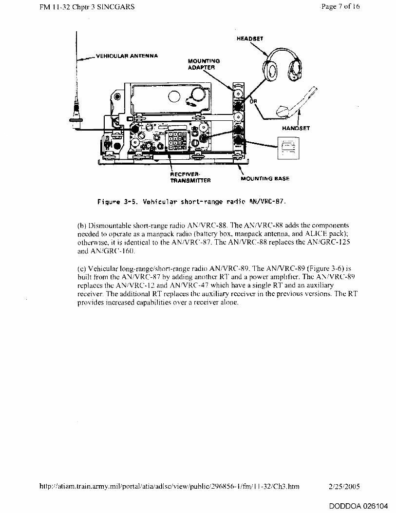
Figure 3-5. Vehicular short-range radio ANiVRC-87.
(h) Dismountable short-range radio ANNRC-88. The ANNRC-88 adds the components needed to operate as a manpack radio (battery box, manpack antenna, and ALICE pack); otherwise, it is identical to the ANNRC-87. The ANNRC-88 replaces the AN/GRC-125 and AN/GRC-160.
(c) Vehicular long-range/short-range radio ANNRC-89. The ANNRC-89 (Figure 3-6) is built from the AN/VRC-87 by adding another RT and a power amplifier. The AN/VRC-89 replaces the AN/VRC-12 and AN/VRC-47 which have a single RT and an auxiliary receiver. The additional RT replaces the auxiliary receiver in the previous versions. The RT provides increased capabilities over a receiver alone.
http://atiam.train.army.mil/portal/atiaiadlsc/view/public/296856-1/frn/ I 1-32/Ch3.htm 2/25/2005
DODDOA 026104

VEHICULAR ANTENNA
HEADSET
MOUNTING ADA ER HANDSET
POWER ttlyiPLIFIER
RECEIVER-TRANSMITTER MOUNTING RASE
J1 {PAI ALIO/ DATA A J3
CG,31166/VAC
J2 IPA1
W1 DATA A J5
C131
FM 11-32 Chptr 3 SINCGARS Page 8 of 16
Figure 3-6. Vehicular long - range/short- range radio AN/VRC-89.
(d) Vehicular long-range radio AN/VRC-90. The ANNRC-90 (Figure 3-7) is an AN/VRC-87 with a power amplifier added for long-range capability. It replaces the AN/VRC-43 and AN/VRC-46.
HEADSET/HANDSET CABLE
ANTENNA AUD/ DATA WA SPEAKER 10 UPSPF-AKER CABLE
Figure 3- 7. Vehicular long-range radio AN/VRC-90.
(e) Vehicular short-range/long-range dismountable radio ANNRC-91. The ANNRC-91 adds the components needed to operate as a manpack radio; otherwise, it is identical to the AN/VRC-89. It does not replace any similar single radio set. The closest configuration
http://atiam.train.army.mil/portal/atia/adlsc/view/public/296856-1/fm/11-32/Ch3.htm 2/25/2005
DODDOA 026105

C3-3ebb/VRC JI
PA I I U HEADSET/HANDSET CABLE
.12
NT-4312/%111c
AN ENNA AUD /DATA B J2
RECEIVER-TRANSMITTER B
W4
.C13-31515/VIIC
UD/DATA A.13
DATA B DATA A .15
FM 11-32 Chptr 3 SINCGARS
Page 9 of 16
would be a combination of a manpack (AN/PRC-77) radio and a vehicular radio (AN/VRC-43 or AN/VRC-46) kept in the same vehicle.
(f) Vehicular dual long-range/retransmission radio ANNRC-92. The ANNRC-92 (Figure 3-8) adds a second power amplifier to the ANNRC-89 to provide high-power capability for both radios in the mount. The second amplifier has its own mount (MT-6353NRC) and obtains its power from cable connected to one of the auxiliary power outputs from the radio mount. In the mounting adapter, the comounted amplifier can only be used with the lower radio, and the separate amplifier can only be used with the upper radio. The ANNRC-92 replaces the AN/VRC-45 and AN/VRC-49.
RECEIVER-TRANSMITTER A W4 SPEAKER LOUDSPEAKER CABLE
Figure 3-8. Vehicular dual long-range/retransmission radio AN/VRC-92.
(3) Airborne versions. The airborne and ground versions are interoperable. They appear physically different to the ground models and to each other. The only change in the airborne models is the face plate that is attached to the different configurations. The RT is identical in all three models, but the add-on modules change the capabilities of the base RT.
(a) The RT-1476/ARC-201 (Figure 3-9) is the basic version of the three. All three versions operate in both the single-channel and FH modes. There are no provisions for remoting the radio or allowing data input.
http://ati am .train .army.mil/portal/ati a/adlsc/vi ew/public/296856-1/fm/11-32/Ch3.htm 2/25/2005
DODDOA 026106

IFM
RF PVVR
NORM
to
OFF
HI
MAN
FILL PRESET 3 4 6
1 FRE°,
CUE
4 5
7 8 9 TIME
FUNCTION 4-1
RXMT
TEST SQ ON
SO OF* LO-v LO
Orr
cc' re MODE
SC FH
NOM FH/M
VOL
FM 11-32 Chptr 3 SINCGARS
Page 10 of 16
Figure 3-9. RT-1476/ARC - 201.
(b) The RT-1477/ARC-201 provides a remote capability for installations where the radio must he located away from the pilot's cockpit. It has a separate radio and remote control panel (Figure 3 - 10) so the pilot can remotely control the radio from his position in the aircraft. The RT-1476/1477 has retransmission capabilities.
http://atiam.train.army.mil/portal/atia/adIsc/view/public/296856-1/frn/11-32/Ch3.htm 2/25/2005
DODDOA 026107

5
CUE
MAN
V H
FUNCTION
R,MT M SO C FF
50 ON v
TEST t
In
at tit
^
n n 1JiJ1,3 1.1
Cal
PINR
I NORM 141
I.
MODE
FH
PRES E T
Ell at
tint t
HOM SC
TMAk
VOL
FM 11-32 Chptr 3 SINCGARS
Page 11 of 16
Figure 3 - 10. RT-1477/ARC- 231 with remote control panel.
(c) The RT-1478/ARC-201 (Figure 3 - I 1 ) is equipped with a DRA for 600 and 1,200 baud data rates. The DRA processes the input signal in the same format as the ground radio in the AD2 mode of operation for use with TACFIRE data terminals. Therefore, it will only communicate with other SINCGARS radios and not with AN/VRC-12 series radios connected to TACFIRE terminals. The RT-1478 is a low density piece of equipment and is the only airborne version that accepts data.
http://atiam.train.army.mil/portal/atia/adIsc/view/public/296856-1/fm/11-32/Ch3.htm 2/25/2005
DODDOA 026108

FM 11-32 Chptr 3 SINCGARS
Page 12 of 16
Figure 3-11. RT-1478/ARC-201.
3-3. Ancillary Equipment
a. There are two main categories of ancillary equipment associated with SINCGARS: remote control devices and data fill/variable storage transfer devices. Other devices that generate signals passed over SINCGARS radios, such as data terminals, are classified as input/output devices.
h. The two primary remote control systems are further divided into intravehicular remotes and external remotes. The intravehicular remote control unit (IVRCU) C-1 1291 is the remote for intravehicular radio control. The SINCGARS remote control unit (SRCU) and AN/GRA-39 are used to remote radios off the main site location.
(1) The IVRCU C-11291 (Figure 3-12) can control up to three separate radio sets in armored vehicles. The IVRCU can be used with either the 1COM or non-ICOM radio. It controls all functions of the three radios from a single station. The monitors can also be connected in parallel so two different operators, such as the vehicle commander and driver, can control the radios from their respective positions in the vehicle. The radio function switch must be set in the remote (REM) operating position for the external control monitor to function correctly. Like the radio, the monitor has BIT functions displayed through the monitor control panel.
http://atiam.train.army.mil/portal/atia/adIsc/view/public/296856-1/frn/11-32/Ch3.htm 2/25/2005
DODDOA 026109

FM 11-32 Chptr 3 SINCGARS
Page 13 of 16
Figure 3-12. IVRCU-C11291.
(2) The SRCU (Figure 3-13) provides securable remoting of a single radio up to 4 kilometers (2.4 miles). The advantage of the SRCU over previous remotes is its ability to secure the wire line between the radio and the terminal set. The SRCU controls all radio functions including power output, channel selection, and radio keying. The remote also provides an intercom function from the radio to the terminal unit and vice versa.
Figure 3 - 13. SRCU.
(3) The AN/GRA-39 (Figure 3-14), previously used to remote single-channel radios, is compatible with the ICOM and the non-ICOM radios. It controls only remote keying of the radio from the terminal set. The operator must set the other functions at the radio location.
http://atiam.train.army.mil/portal/atia/adlsc/view/public/296856-1/fm/11-32/Ch3.htm 2/25/2005
DODDOA 026110

LINE BINDING POSTS AN/GRA-39B
FM 11-32 Chptr 3 SINCGARS
.!(
1 1
VP TO 2 MILES
LINE BINDING POSTS
C•239
Page 14 of 16
C-2328
W!Ij.
RADIO CONNECTOR
AUD/DATA
Figure 3-14. AN/GRA-39 with SINCGARS.
c. The data fill devices provide a means to transfer the required variables for the FH mode from unit to unit and to enter the variables into the radio.
(1) The MX-10579 (Figure 3-15) is used with the non-ICOM radio only. The MX-10579 holds up to 13 hopsets and two transmission security keys (TSKs) variables. It can he filled one location at a time or hulk loaded with a complete fill. The MX-8290 is used with the ICOM or the non-ICOM. The MX-18290 holds 13 hopsets and 6 TSK variables.
http://atiam.train.army.mil/portal/atia/adIsc/view/public/296856-1/fin/11-32/Ch3.htm 2/25/2005
DODDOA 026111

FM 11-32 Chptr 3 SINCGARS Page 15 of 16
Function Switch
Check Indicator
Initiate Switch
Selector for HopsetiTSK
Figure 3-25. ECCM fill device MX-10579.
(2) The electronic notebook (EN) AN/CYZ-7A (Figure 3-16) is a small hand-held data memory device similar to a small calculator. It can be loaded with complete or partial SOI and the FII variables for operation of SINCGARS. It provides the operator with an automated search method to locate call signs and frequencies for use in any number of networks. The EN replaces the paper SOI for use in the field.
http://atiam.train.army.mil/portal/atia/adlsc/view/public/296856-1/fm/11-32/Ch3.htm 2/25/2005
DODDOA 026112

'
dl -
P
E
7-1 L7;11
C
0 FF1
TES t"
yjj wi,
rS HF ON T
6E343
FM 11-32 Chptr 3 SINCGARS Page 16 of 16
VIDEO DISMAY
Fi gure 3-16. EN AN/CYZ- 7A.
(3) Currently, an operator requires two fill devices to put a secure FH radio into a network. One device loads the radio and the second loads the secure device (VINSON or ICOM). The National Security Agency (NSA) is developing a single device to hold all the required variables and the SOI contained in the EN. Until the device is fielded, the operator must carry both devices.
http://atiam.train.army.mil/portal/atia/adlsciview/publie/296856-1/fm/11-32/Ch3.htm 2/25/2005
DODDOA 026113
FM 11-32 Chptr 4 FH Networks Page 1 of 5
Chapter 4
FH Networks
4-1. FH Variables
a. SINCGARS hops or changes frequencies about 100 times per second. The radio uses digital processing to control the hopping sequence and the pattern so that the RT arrives at the same frequency at the same time. This ensures the information sent is received and can be decoded. If the sequence were truly random, the receiver could not predict what frequency to hop to next, so the actual sequence is developed in a pseudorandom fashion. The RT uses identical sequencers so the receiver can predict what frequency the transmitter will hop to next. SINCGARS uses the following four variables to synchronize the hopping sequence:
• Hopset.
• TSK.
• Net identifier.
• Julian day/zulu time.
Unless the receiver has all four identical variables, the sequence appears random to a radio outside the network. FH degrades enemy detection capabilities because the output is basically a random pattern. Additionally, several different networks operating in the same area prevent identifying a particular frequency or hopping pattern with any one network.
(1) The hopset is the list of frequencies the frequency manager authorizes for use by a particular unit. The hopset can be specified by a list of discrete frequencies or ranges and groups of frequencies. When a hopset is entered into the radio, the display shows Fxxx. The letters xxx represent a three-digit number that specifies the hopset in use.
(2) The TSK is the digital code that controls the hopping sequence circuits. When FH, the receiver must predict what frequency the transmitter will move to next. The hopset specifies which frequencies the receiver can expect to see. The TSK tells the RT the order the frequencies will appear. SINCGARS uses a pseudorandom code sequence so both radios hop in the same order. The radio's digital circuits generate the hopping sequence, and if both start in the same place and time, they repeat identical codes.
(3) Both radios must start at the same place in the code so the identical code sequence is developed. The net identifier is the variable that determines where in the code to start. The net identifier is loaded into the radio as part of the initial fill of variables. Each network has a unique identifier, therefore, the starting place in the sequence is different for all networks.
(4) Using the same TSK, the netted radios hop in the same sequence over a given list of frequencies. The same net identifier starts them at the same place in the sequence. The only variable left is WHEN to start the hopping sequence. SINCGARS uses Julian day/zulu time as the time variable. The time is entered as day, hours, and minutes. Seconds start when the minute variable is entered. The time set on the radios is arbitrary as long as both radio clocks are within
http://atiam.train.army.mil/portal/atia/adIsc/view/public/296856-1/frn/11-32/Ch4.htm 2/25/2005
DODDOA 026114

FM 11-32 Chptr 4 FH Networks Page 2 of 5
. +4 seconds of each other. The late net entry (LNE) mode allows the clock time to he off up to +59 seconds and still maintains synchronization. Time can also be entered during ECCM remote fill (FRF) as described below. In any net, only the NCS places the RT mode switch in the frequency hopping/master (FH/M) position. This ensures that the NCS updates the net time synchronization.
b. The variables are unclassified for accounting purposes but are still sensitive in nature. The hopset and TSK variables are stored in the EN or fill device and are loaded into the radios electronically. ECCM fill devices can also be filled by a tape reader and paper tape. The SINCGARS radio is never filled directly from a tape reader. The operator must enter the time, along with any single-channel frequencies, on the keyboard. Although the variables are unclassified, they are kept in the EN with portions of an SOI that is classified. This properly controls distribution of the variables.
c. ERF is another method of loading radio variables. The only stipulation is that the TSK variable must already have been loaded manually. Security regulations state that the radio link must be in the secure mode before ERF transmission. ERF loading can be done in either the single-channel or FH mode. The single-channel mode is called cold start. Cold start is performed when the radio-channel selector is in the manual frequency position, and the function switch is in the FH mode. Operators perform radio checks on the manual frequency in the nonsecure mode, move to the secure mode, and then perform ERF functions. Under no circumstances will the TSK he transmitted over the radio system. The TSK must be physically loaded by fill device into the radio.
d. SINCGARS uses two single-channel frequencies during FH operations: manual and cue. The manual frequency is used for initial network activation (as described above). It brings outside subscribers into the network when the need arises. The cue frequency allows a subscriber outside the hopping network to notify the network that he desires to communicate with someone in the network. When the single-channel radio calls on the cue frequency, all radios in the hopping network receive audible and visual indications. Essentially, the outside subscriber calls the network, but the NCS or a designated station answers the call. The cue call must initially be made nonsecure for the SINCGARS radio to recognize the signal coming in.
4-2. Unit Standing Operating Procedure (SOP) Considerations
a. The network planners and managers for previous generation single-channel networks considered many options during planning and operating a network. SINCGARS requires the same considerations and adds many more peculiar to FH networks. Some of the FH peculiarities are similar to single-channel planning steps but are more complex (for example, frequency selection versus hopset allocation). This chapter distinguishes between items that apply to both versions of SINCGARS (ICOM and non- ICOM) and items that are unique to each version pertaining to hopsets and TSK variables. The appendix contains a suggested SOP for SINCGARS.
b. The primary consideration for network structure is the capabilities of available equipment. If all radios are capable of SINCGARS compatible FH mode, the network operates in FH. However, if just one of the required radios is limited to single-channel operation, the entire network must operate single-channel. To the extent possible, networks capable of the FH mode should remain in the FH mode to counter Threat electronic countermeasures (ECM) abilities. This problem usually occurs only during combined operations when units must communicate with allied nations. The alternative is to ensure, through prior planning, that a SINCGARS FH radio is cross-attached to the unit concerned.
c. Frequency compatibility and channel spacing of the equipment in the network must be considered in overall planning. AN/VRC-12 series radios and most allied nation VHF-FM radios operate over the
http://atiam.train.army.mil/portal/atia/adlse/view/public/296856- l /fm/I I-32/Ch4.htm 2/25/2005
DODDOA 026115

FM 11-32 Chptr 4 FH Networks Page 3 of 5
frequency range from 30 MHz to 76 MHz. Planners must ensure single-channel operating frequencies are within that range if the network, even if remotely possible, requires communications with the older radios. Older radios operate on 50 kHz spaced channels, while SINCGARS operates on 25 kHz spaced channels. Therefore, the frequencies specified for single-channel networks must be assigned based on the equipment in the network and whether 25 or 50 kHz spacing can be used. The same is true for the cue frequency; it must be on a 50 kHz spaced frequency so any radio can access the network. The BECS automatically assigns the cue frequency on a 50 kHz spacing basis.
d. The unit SOP should address network activation (cold start) and remote fill procedures. For cold start, radio operators load the hopset, COMSEC, and TSK variables before net activation. ERF loading of a fill should be used only if the new subscriber does not have a fill device containing the network's operational hopset. The NCS requests the new subscriber to authenticate using current authentication tables in accordance with procedures specified in FM 24-35 before transmitting the ERF. At a minimum, the radio must have the TSK installed before ERF transfer.
e. The corps/division NCS determines the time reference the network will use. For simplicity, SOPs should specify that the NCS use Greenwich Mean Time (GMT) or zulu time as the general reference for network operations. It should also specify using the last two digits of the Julian date as the mission day. This eases the ability of operating in two networks at the same time.
f SOPs should specify using minimum power to provide communications. The adjustable power output capability allows users to tailor the radio for the best possible communications in any circumstance. If the network requires extended range, the SOP should specify using better types of antennas over increasing power. Directional or ground-plane antennas (for example, the 0E-303 or 0E-254; the RC-292 cannot be used with SINCGARS radios) allow communications over longer distances without increasing the power output. Combining lower power and ECCM methods lessens the probability of Threat detection and interception. Terrain masking and other ECCM techniques should be used to the maximum extent possible. (See FM 24-33.)
g. Using a radio retransmission system is another way of increasing radio transmission range. Retransmission for SINCGARS is simple to set up but prior planning must be done to ensure availability of frequencies or hopsets. SOPs should address the equipment constraints listed in Chapter 5, distribution of the variables to the retransmission station, and the subscribers who require access to the retransmission station. All retransmission operations require two net identifiers for each side of the retransmission station.
h. The unit SOP should specify usual hopset changeover times for network operations. This serves as a guide for normal operating conditions. The hopset may be changed more often if the mission dictates. Units may receive only a few different hopsets. The SOI generated by BECS automatically assign frequencies to maximize use of the available hopsets and frequencies.
i. Since SINCGARS can hold six preset hopsets and eight single-channel frequencies, unit SOP should specify locations reserved for certain functions. Cue and manual frequencies must be loaded in their designated positions for operating the radio properly. The six presets for single-channel frequencies and hopsets should have designated functions so the NCS can simplify network control and operation. Table 4-1 shows a suggested method to allocate the fill positions. In some cases, the single-channel assignments list two options. The first choice is for the radio, if active in a single-channel nonhopping network. The second selection is for a radio that operates full time in hopping mode using the hopsets specified. Position 1 for the FH mode is left to fill with the hopset that will be used most often in the unit. In the FH mode, position 5 is filled with the NRI hopset, secondary command channel, or it may be used for coordination outside normal networks when required (as in joint or rear battle operations).
http://atiam.train.army.mil/portal/atiaiadlse/view/public/296856-1/m/ 1 1-32/Ch4.htm 2/25/2005
DODDOA 026116

FM 11-32 Chptr 4 FH Networks Page 4 of 5
Position 6 is designated for the medical support or medical evacuation (MEDEVAC) frequency. All of the assignments assume a single RT is available for use in a particular installation. A single radio limits hopset loading of preset positions to the six most important nets depending on the situation. SINCGARS can store the six most used hopsets or frequencies. Previously, the operator had to dial in each frequency as it was required. The radio sets containing two RTs are more flexible in assignment of frequencies and hopsets. Generally, for two radio configurations, the radio with highest possible output contains the frequencies or hopsets for the primary command network, fire support network, and NRI network (if required).
Table 4-1. F ill position allocation.
SINGLE CHANNEL
POSITION 1 PRIMARY NETWORK FREQUENCY: NRI CUE FREQUENCY
POSITION 2 INTELLIGENCE NETWORK
POSITION 3 COMMAND RETRANSMISSIOWNRI AREA FREQUENCY
POSITION 4 ADmiNiSTRATIVE LOGISTICS
POSITION 5 NRI- ADJACENT COMMAND OR REAR BATTLE FREQUENCY
POSITION 6 MEDICAL ASSISTANCE FREQUENCY
FREQUENCY flOPSETS
POSITION 1 PRIMARY COMMAND NETWORK HOPSET --,
POSITION 2 INTELLIGENCE NETWORK HOPSET
POSITION 3 COMMAND RETRANSMISSION HOPSET
POSITION 4 ADMINISTRATIVE. LOGISTICS HOPSET
POSITION 5 NRI SECONDARY ADJACENT COMMAND DR REAR BATTLE HOPSET
POSITION 6 DIRECT SUPPORT MS} FIRE SUPPORT HOPSET
j. Distribution schemes for the TSK variable for the two ground versions are identical. TSKs will he changed every 30 days with a maximum key period of 90 days in emergency situations. In both versions, TSKs are area specific. If missions require users to operate outside the normal areas or to operate with adjacent corps units, the appropriate TSK must be transferred to units involved.
k. The non-ICOM radio can hold two TSK variables in memory. One is stored in the main operating memory for use as the current TSK. The other is held in a secondary memory until called up for installation into the radio as the operating TSK. Internal circuits erase the current TSK when the secondary is installed. This means that once the secondary TSK is loaded into the main memory, the operator cannot go back to use the first unless he has a fill device with the first TSK and reloads it into the radio. The TSK for the non-ICOM radio will be common to the corps. This allows members of higher echelon networks to access the lower echelon networks with an ERF of the remaining hopping variables.
I. The unit SOP should address emergency destruction plans for all cryptographic devices. The VINSON and the new ICOM radio are controlled cryptographic items (CCI) and must be destroyed if the unit is overrun. SOP should specify what actions to take and what command level is authorized to implement the plan.
http://atiam.train.army.mil/portal/atia/adIsc/view/public/296856-1/fm/11-32/Ch4.htm 2/25/2005
DODDOA 026117

FM 11-32 Chptr 4 FH Networks Page 5 of 5
m. The final item for SOP consideration is equipment setup for data networks and designation of the network as a dedicated data network or timeshared voice network. Units which use data devices and networks on a regular basis should dedicate separate net identifiers for the voice and data traffic. SOPs should address hopset allocations and equipment data rate settings for the particular data terminals and the radios.
n. The unit SOP for planning single-channel radio communications should address the following:
• Designation of preset channel functions.
• Operating procedures for single-channel and FH modes.
• Retransmission procedures.
• Hopset use.
• TSK assignments and use.
• Data network configurations.
• Common network time designation.
• Emergency destruction plans.
The planning requirements for SINCGARS are different from those of previous generation radios. Using these criteria and following the operating procedures specified in FM 24-19, units can expect highly responsive communications support from SINCGARS. The brigade/battalion signal officer (BSO) and brigade/battalion signal NCO (BSNCO) are responsible for ensuring their unit can communicate to fight the battle. Aggressive action is needed to properly train operators and planners in using the new radios.
http://atiam.train.army.mil/portal/atia/adlsc/view/public/296856-1/fm/11-32/Ch4.htm 2/25/2005
DODDOA 026118

FM 11-32 Chptr 5 SINCGARS Planning Page 1 of 13
Chapter 5
SINCGARS Planning
5-1. Network Requirements
a. The initial operations plan and unit SOP determine the type of net needed. The network planner must answer the following questions when planning communications support:
• What type of information is to be passed: data, voice, or both?
• Does the unit require communications with users normally not in its network?
• Is the network a common-user or a designated membership net?
• Is retransmission needed to extend the network's range?
• Is an NRI station required?
b. The assistant division signal officer (ADSO) and the unit G3/S3 work together to answer all questions. Once the questions are answered. initial planning and coordinating the network can begin. Many items should become SOP.
5-2. Data Nets
a. The DRA exists in all versions of SINCGARS as an integral part of the radio. The capability for passing different data rates is the DRA in the radios. Without the DRA, the radio can only operate at 16,000 bps. Most tactical data terminals operate at speeds under 4,800 bps, so the DRA is required in all but a few cases. Specific units that require DRA and associated data terminals are--
• Maneuver units - Maneuver Control System (MCS).
• Field artillery (FA) and data terminal devices.
• ADA - Forward area air defense command, control, and intelligence (FAADC2I).
• Military intelligence (MI) - All Source Analysis System (ASAS).
The ADA, FA, and MI data systems will normally be transmitted over the Enhanced Position Location Reporting System (EPLRS) or the Joint Tactical Information Distribution System (JTIDS). In the interim, a limited amount of this traffic can be passed over CNR systems until EPLRS and JTIDS are fully fielded. The only data system not addressed here is the Combat Service Support Control System (CSSCS), the Army's logistics computer system. CSSCS data will normally be transmitted over ACU networks and not over CNR systems. If the mission dictates, however, CSSCS data could be passed via SINCGARS.
h. Brigade and battalion commanders use tactical facsimile devices instead of the radio teletypewriter (BATT) for passing text or overlays. The facsimile currently used is the AN/UXC-7. The AN/UXC-7 can transmit one page of data in 12 seconds at 16 kilobits per second (kbps). SINCGARS and the mobile
http://atiam.train.army.mil/portal/atia/adIsciview/public/296856-1/fm/11-32/Ch5.htm 2/25/2005
DODDOA 026119

CALL 'AR
FM 11-32 Chptr 5 SINCGARS Planning Page 2 of 13
subscriber radiotelephone terminal (MSRT) are the primary means of transmitting facsimile traffic between users in mobile situations. The advantage of using SINCGARS for facsimile is that a single broadcast can provide the information to several addressees at the same time. Subscribers should transmit facsimile data over wire to the ACU multichannel network when available to reduce electronic signatures.
c. The non-ICOM and ICOM radios can pass data traffic with a DRA installed. The only difference between the two versions is the method of selecting the data rate. The non-ICOM radio has a selector knob on the face of the radio (Figure 5-1). For voice operations, the selector is in the OFF position. When used for data traffic. the operator turns the knob to the correct data rate position (600 to 16,000 bps). The ICOM radio data rate is set through keypad entry of the proper data rate (same as non-ICOM rates).
Figure 5-1. Data rate selector--non-ICOM radio.
(1) The non-ICOM radio accepts data rates of 75; 150; 300; 600; 1,200; 2,400; 4,800; and 16,000 bps. The ICOM radio accepts data rates of 600; 1,200; 2,400; 4,800; and 16,000 bps. The radio also provides error correction (for speeds 4,800 bps and below) above the correction done by the various terminal devices. Although operating at 16,000 bps may be faster, it may not result in transfer of accurate information. The trade-off for speed is longer transmission times for the radio. The data rate should be maintained at the fastest level possible to minimize transmission time and still convey accurate information. The terminal equipment will be the determining factor in most cases.
(2) The data rate selectors have two special data rate positions: AD1 and AD2. These are designed for operation with TACFIRE computers and data terminals. AD1 is used to communicate with other TACFIRE terminals connected to non-SINCGARS radios. AD2 is used for pure SINCGARS radio networks. However, both radios must be equipped with a DRA.
d. When using, the same hopset for voice and data networks, interference from different networks can prevent transferring accurate digital data. If this happens in high-volume communications areas, the ADSO considers allocating a separate hopset to the data network.
e. The SINCGARS radio interfaces with several types of DTE. SINCGARS provides automatic control of the radio transmission when a data device is connected. It disables the voice circuits during data transmissions, preventing voice input from disrupting the data stream. Disconnecting the data device during emergency situations overrides the disable feature. A single cable from the DTE to the radio or mounting adapter connects most DTEs .
http://atiam.train.army.miliportal/atia/adIsc/view/public/296856-1/fm/11-32/Ch5.htm 2/25/2005
DODDOA 026120

DATA DEVICE A
8T DATA DEVICE
A/F
A/D
FM 11-32 Chptr 5 SINCGARS Planning Page 3 of 13
(1) The primary data devices used will be the facsimile (UXC-7 or GXC-7A), teletype terminal AN/UGC-74, and the various computer terminals (MCS, AFATDS, ASAS, or FAADC21). All of these devices are cabled in the same manner (Figure 5-2). The only difference between devices is selecting data transmission speeds. To optimize the abilities of the data devices and SINCGARS. the devices should operate at the fastest possible data rate. The radio and DTE error correction abilities should be compared to provide the fastest transmission time and the most accurate transfer of information. Data devices used must be capable of SINCGARS data bit streams.
VEHICULAR RADIO
RT U
RT A
A/F
A/D
A/F
A/D
C HAND- SET 13
HAND. SET A
LOUD-SPEAKER
MOUNTING ADAPTER
DATA DEVICE. e
HAND SL M A NPACK RADIO
Figure 5 -2. Cabling for voice/data operation.
(2) TACFIRE uses a special configuration and data rate selection. Figure 5-3 shows the physical connections from the computer terminals to the radio. Data device A is associated with RT A and device B with RT B. The data rate selector is set to either ADI for communications with non- SINCGARS radios or AD2 for pure SINCGARS networks. Figure 5-3 shows connections that also apply for the digital message device (DMD) AN/PSG-2. The TACFIRE devices should be set as follows:
o Data rate - 1,200 baud.
o Keytime - 0.7 second.
If the TACFIRE system experiences high error rates, the operators may have to change to 600 baud to improve reliability. TACFIRE data devices may be remoted from the radio using either
http://atiam.train.army.mil/portal/atia/adlsc/view/public/296856-1/frn/11-32/Ch5.htm 2/25/2005
DODDOA 026121

DEVICE A
J2
JJ
Je.
J6
J6
VEHICULA R RADIO
DEVICE RT
RI A
A/F
A/ D
A/F
A/D
LOUD SPEAKER
HAND-SET A
REMOTE
CONTROL C.2.3213 ,
AN/GRA-39
1I
FM 11-32 Chptr 5 SINCGARS Planning Page 4 of 13
the AN/GRA-39 or the SRCU (Figure 5-4). The AN/GRA-39 can only be used with TACFIRE and not with other data devices since it can only handle analog signals. The SRCU can be used in all cases.
MOUNTING ADAPTER
Figure 5-3. Cabling for TACFIRE.
CARLE PART OF C- 2329
LOCAL CONTROL C-232S/ AN/GRA as
RADIO CONNECTQR
'USF. JZ FOR RA010 B OPERATION . J3 FOR RADIO A OPERATioN,
TACI- IRE DEVICE (AIN/IG3C-21, AN/RSG 2 AN•G5O-122. AN,GY% 29 OR C-9991)
AULD/ DATA 0 J2.
AUD '13ATA A .13-
MOUNTING ADAPTER
Figure 5- 4. Routing of TACFIRE devices.
5-3. Secure Devices
a. SINCGARS uses two basic devices to provide secure voice communications capability. The non-ICOM radio uses the VINSON KY-57 for ground applications and the KY-58 for airborne configurations. The ICOM radio uses an internal COMSEC module whose encryption format is compatible with current VINSON devices. The devices are compatible provided they are loaded with the
http://atiam.train.army.mil/portal/atia/adIsc/view/public/296856-1/frn/1 I -32/Ch5.htm 2/25/2005
DODDOA 026122

FM 11-32 Chptr 5 SINCGARS Planning Page 5 of 13
same traffic encryption key (TEK).
(1) The VINSON secure device has six preset positions-- five for the TEK and one for a key encryption key (KEK). The five TEK positions allow operation in five different secure networks. The KEK allows changing or updating the TEK through over-the-air (by radio transmission) fill.
(2) The ICOM secure module retains one TEK per preset hopset/net identifier and one KEK. The corps signal planning element is responsible for ensuring the TEK is distributed to all units in the corps.
(3) The variables are loaded and updated the same way in both devices. Initial loading is done by the KYK-13. Variables can be updated by a second manual fill or by over-the-air remote fill. The NCS operates the KYX-15 as the control device for network secure variables. In accordance with COMSEC regulations, only the TEK may be transmitted over the air. The KEK must still be physically loaded into either the VINSON or ICOM radio. Encryption variables are controlled through COMSEC channels and are accounted for per TB 380-40.
h. Data input to the radio is interleaved into the radio's digital data stream. The VINSON or ICOM circuits encrypt the data before transmission. However, digital data may be encrypted before inputting the information to the radio. COMSEC variables must he common for the transmitting and receiving terminals. This is coordinated between the two units passing the information.
5-4. VHF-FM Retransmission Stations
a. The FM retransmission station operates on the command network to which it is subordinate, unless specifically tasked. The primary radio monitors the command/operations network and the secondary provides the retransmission link. Prior planning provides the retransmission station with the appropriate variables for the command network and retransmission network. The unit SOP should direct how the retransmission variables are assigned in accordance with possible alternatives.
b. Frequency planners for the AN/VRC- 1 2 radios were primarily concerned with frequency separation and harmonic interference. Those criteria are still important for SINCGARS but vary for specific system configurations. SINCGARS can perform the retransmission function three ways. The network--
• Can he set up for standard AN/VRC-1 2 retransmission--single-channel to single-channel.
• Can he of mixed mode--FH to single-channel or vice versa.
• Can use its full capability of FH to FH.
These options make retransmission flexible in operation. They also increase the prior coordination required before deployment. This ensures all users have access to the retransmission function.
(1) Single-channel to single-channel operation has the same requirements as previous VHF- FM retransmission configurations--10 MHz separation between fl and 12 (Figure 5-5). Physically moving the antennas farther apart or lowering power output lessens the separation in frequency. Table 5-1 shows the relationship between frequency and physical separation. The network NCS must control the retransmission station in regard to changing off the command hopset to ensure continuous communications for the unit.
http://atiam.train.army.mil/portal/atia/adIsciview/public/296856-1/fm/11-32/Ch5.htm 2/25/2005
DODDOA 026123

FM 11-32 Chptr 5 SINCGARS Planning Page 6 of 13
RETRANSMIT RADIOS C D
Figure 5-5. Retransmit operation.
Table 5-1. Minimum antenna distance separation.
Minimum frequency separation required
High power separation
PA power separation
10 MHz 7 MHz 4 MHz 2 MHz 1 MHz
5 feet 10 feet 50 feet
200 feet 350 feet
5 feet 60 feet 150 feet 400 feet 800 feet
(2) FH to single-channel operation is the simplest mode to set up and operate. There is no requirement for frequency or physical separation. The single-channel frequency can be part of the hopset used on the FH side of the retransmission but should be an independent frequency if available. This method allows a single-channel radio user access to the FH network in an emergency situation. Continual access to the FH net using this method should be avoided to prevent lessening the ECCM capability of the SINCGARS systems.
(3) FH to FH operation requires at least one of the hopping variables from FH I to FH2 to be different. Any one or a combination of several variables may change, but the preferred method is with the same hopsets but with different net identifiers for each side of the retransmission.
c. The retransmission station operator functions like the network NCS for the outstation link. In this function, the operator answers all cues, ERF, hopset variables and authenticates net entry. The retransmission operator must ensure the outstation RT is placed in the FH/M mode. This ensures timing on this link is established and maintained.
d. SINCGARS can operate as either a secure or nonsecure retransmission station. The radios automatically pass secure signals even if the retransmission radios are operating nonsecure. However, the retransmission operator cannot monitor the communications unless the secure devices are filled and in the cipher mode. Figures 5-6 and 5-7 show the equipment configurations for nonsecure and secure retransmission. The ICOM radio requires a single cable, the same as the non-ICOM, nonsecure retransmission.
http://atiam.train.army.mil/portal/atia/adIsciview/publie/296856-1/fm/11-32/Ch5.htm 2/25/2005
DODDOA 026124

AS.3900
&
1 m RT-143J96 j2e
n J10 .-----11Z% i J2 • w22 J4 a JG* •
RT-141s S. —1 J54
AM-77311
KY-57
PAY-6353 451 LS-671 RADIO AUDIO
KY-57
a/A0 RADIO RUDIO
FM 11-32 Chptr 5 SINCGARS Planning Page 7 of 13
AS-3000 AS-30011
figure 5-6. SINCGARS nonsecure retransmission.
AS-3900
1 erb J1 t'2 J2•
4
M1-63132 ■••••■•■
Figure 5-7. SINCGARS (non-ICOM) secure retransmission.
e. The retransmission station should use ground-plane antennas when time permits to extend range at the lowest possible power. When the radios operate in the power amplifier (PA) power setting, at least one radio must use a dismounted antenna for physical separation. Physical separation decreases radio frequency (RF) interference. The antenna must be a broadband antenna such as the 0E-254 or the OE-303.
f. SINCGARS radios are compatible with noise, tone, and digital squelch signals at all times. No special planning is required for the different squelch systems on the various radios in the network.
5-5. NRI Systems
a. NRI provides a SINCGARS subscriber access to the ACU multichannel system or a telephone user access to the CNR network. There are 44 total NRI systems in the notional five-division corps. Although each LENS and SENS contains the NRI mounting assembly. current fielding plans for MSE to place 4 NRI systems in the division signal battalion and 24 in the corps signal brigade (based on one per node center (NC)). The division's equipment is presently located in the SENS shelters, which are colocated with the maneuver brigade CP and the engineer battalion CP, or in the division support command (DISCOM) LENS shelter. These locations are tentative, based on mission requirements to provide the best support in the forward areas. The corps NRI systems deploy with the LENS or SENS throughout the corps area.
b. NRI systems operate in the FH mode to the maximum extent possible to minimize the possibility of direction finding of the CP or switch locations. Deployment of the corps NRI systems (including the
http://atiam.train.army.mil/portal/atia/adIsc/view/public/296856-1/fm/11-32/Ch5.htm 2/25/2005
DODDOA 026125

FM 11-32 Chptr 5 SINCGARS Planning Page 8 of 13
division assets) is based on an area concept.
(1) Each NRI station establishes its own hopping variables and acts as an NCS. The NRI systems numbered NRI 1, 2, and 3 are associated with the maneuver brigades. NRI 4 can be located with any switch in the division area depending on the mission. The NCS function for the NRI station is to provide a central time reference. It also allows access using the cue frequency for all NRI subscribers. The term "habitual association" means a particular unit deploying in support of another. In this case, it means the association of a particular NRI number to a unit area and not a signal unit to a combat unit. The first brigade area uses the call sign and telephone directory number for NRI 1 and so on across the divisional areas. The numbering plan for the NRI systems is the same for all divisions. This scheme allows any radio or telephone subscriber to easily identify the NRI device he needs to access for a call.
(2) The corps area is also divided into communication zones that reflect an extension of the divisional boundaries to the corps rear boundary (Figure 5-8). Each NRI station is an NCS and operates on its own set of hopping variables. The NRI systems are numbered sequentially 1 through 5 and are deployed left to right across that NRI zone. Again, the subscriber can easily identify the NRI device to access.
http://atiam.train.army.mil/portal/atiaiadIsc/view/public/296856-1/ ni/11-32/Ch5.htm 2/25/2005
DODDOA 026126
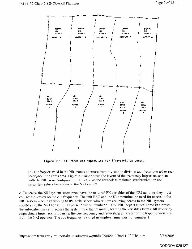
ZONF. 7
tont i m ( NOPRF 1 A NOPSET A
(
I (
r PS / XIP5 NRI NRI
rORRS
ION E 3 ZONE 1
NOPSEI
CUR PS EtR I IIINF f
If
1'1 OCTET
CORPS NRI LURE S
x
X X ,
NRI NRI NPR ZONE zoNt ZONE
INV 1 myz Ow A
HOPSET NOOSET H C1P5E7 A 0 A
X)I
NRI NRI ZONE ZONE ow OIV
H MSC PIS:IPSO A
FM 11-32 Chptr 5 SINCGARS Planning Page 9 of 13
Figure 5-8. NRI zones and hopset use for five -division corps
(3) The hopsets used in the NRI zones alternate from division to division and from forward to rear throughout the corps area. Figure 5-8 also shows the layout of the frequency hopset reuse plan with the NRI zone configuration. This allows the network to maintain synchronization and simplifies subscriber access to the NRI system.
c. To access the NRI system, users must have the required FH variables of the NRI radio, or they must contact the station on the cue frequency. The unit BSO and the S3 determine the need for access to the NRI system when establishing SOPs. Subscribers who require recurring access to the NRI system should store the NRI hopset in FH preset position number 5. If the NRI hopset is not stored in a preset, the subscriber may still access the system by either manually loading the variables from a fill device by requesting a time hack or by using the cue frequency and requesting a transfer of the hopping variables from the NRI operator. The cue frequency is stored in single-channel position number 1.
http://atiam.train.army.mil/portal/atia/adlsciview/public/296856-1/fiii/11-32/Ch5.htm 2/25/2005
DODDOA 026127

FM 11-32 Chptr 5 SINCGARS Planning Page 10 of 13
d. Unlike previous NRI systems, the new equipment can provide secure NRI access end to end. VINSON-type devices secure the SINCGARS radio link. The KY-90 and the KY-68 digital subscriber voice terminal (DSVT) or the physical security of the TA-1035 secures the wire link inside the MSE system. The TEK for all VINSON-type secure devices will be common throughout the corps so that secure communication is available to the greatest number of subscribers. The corps G3/G6 coordinates distribution of the key list or variables to all units in the corps. Each network has a unique KEK and still provides selective remote keying of the secure devices if a unit is captured. If a radio user does not have the proper COMSEC key, the call may be completed in the nonsecure mode. However, the NRI operator must inform both parties that the call is nonsecure and that proper radiotelephone operator (RATELO) procedures must be followed.
e. The following subparagraphs outline procedures for placing NRI calls from both the radio and telephone sides of the system. The NRI operator controls and monitors all calls to ensure the subscribers use proper RATELO procedures.
(1) A CNR user calling from a radio into the NRI system switches to the NRI hopset or cue frequency and calls the NRI closest to his location. If the call is on the cue frequency, the NRI operator determines if the caller is authorized use by authentication. If the caller authenticates correctly, the operator transfers the NRI hopping variables to the caller and continues the call in the FH mode. The call should not be made in the single-channel mode. The caller identifies the wire subscriber to the NRI operator by radio call sign or telephone number. The NRI operator looks up the individual in the telephone directory. Then he calls the telephone number of the intended recipient and transfers control of the call to the two users.
(2) The telephone user desiring to call a radio subscriber looks up the telephone number of that subscriber's NRI system. The user tells the NRI operator who he wants to contact and, if possible, in what network the radio is operating. The NRI operator notifies the radio subscriber on the subscriber's network cue frequency. The radio subscriber tunes the radio to the NRI hopset to complete the call. If necessary. the NRI operator will transfer the NRI hopping variables to the radio subscriber.
f. The KY-90 and the C-6709 are currently used for NRI systems. Both have similar functions, but the C-6709 is an analog device and cannot be secured over the wire line to the switchboard.
(1) The KY-90 (Figure 5-9) is the digital interface device designed for MSE and TRI-TAC digital switches. The KY-90 appears as a KY-68 DSVT to the switched network and operates in the network as a secure terminal. This provides a secure system from the telephone user to the NRI system operator. The KY-90 also stores up to nine TEKs compatible with VINSON-type devices that secure the radio link of the complete circuit. This provides an end-to-end secure (either encrypted or physically secure) circuit for the user placing a call either into or out of the system. Figure 5-10 shows the equipment hookup for the KY-90 to SINCGARS. It should be noted that only voice traffic is possible when using the KY-90 and the MSE system.
http://atiam .train.army.miliportal/atia/adlsciview/public/296856-1/fm/11-32/Ch5.htm 2/25/2005
DODDOA 026128

FM 11-32 Chptr 5 SINCGARS Planning Page 11 of 13
PPILMIr FRAIL
Figure 5-9. Secure digital NRI unit KY-90.
J2 RADIO CONNECTION
RT-9
0
RT-A °
0
AUD/DATA
KY-90
Figure 5 - 10. Equipment hookup--KY-90 to SINCGARS.
(2) The C-6709 (Figure 5-11) is the analog interface device used with analog switches or with digital switches equipped with analog conversion cards. The radio link can be secured by VINSON-type devices, but the wire line must be kept within a controlled area to secure the wire. The switchboard treats the C-6709 as a four-wire telephone subscriber similar to the TA-341 telephone. Figure 5-12 shows the equipment hookup for the C-6709 to SINCGARS.
http://atiam.train.army.mil/portal/atia/adlsc/view/public/296/356-1/fm/11-32/Ch5.htm 2/25/2005
DODDOA 026129
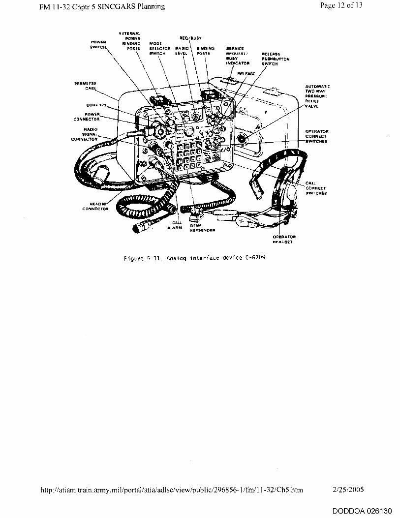
AUTOMAT! c TWO WAY PRESSUR E REUEr
AL VE
OPERATOR CONNECT swarcHis
POWE CONNECTOR
RADIO SIGNAL
CONNECTOR
Page 12 of 13 FM 11-32 Chptr 5 SINCGARS Planning
\
xTE R NAL ROWER
BINDING POS16,
REQ/ILLISr
RADIO BINDING LEVEL poST6
SERVECE
RP-QUEST/ BUSY INDICATOR
RELEASE PUSPIlkurnoN SwETCN
u b ,51.4 -''---- -- mwrwwww*I i■'* — • 1 1 — ,.■..
_N i
_ , 0 I f# Wei*, \‘.. ..
s' r 4 * "0110
r - , . . ' el I— 17 -' . ■ 1?---- if '- '4''* * *". CALL rek:4-111..76
ALARM OTAIP KEYSENDER
HEAD SE CONNECTOR
CALL CO MN ECT SwITCNES
RELEASE
POWER svorci
SEAMLESS CABS
OTNF
MOOR SELECTOR SWITCH
OPERATOR ApAnsET
Figure 5-11_ Analog interface device C-6709_
http://atiam.train.army.mil/portal/atia/aclise/view/publie/296856-1/fm/11-32/Ch5.htm
2/25/2005
DODDOA 026130
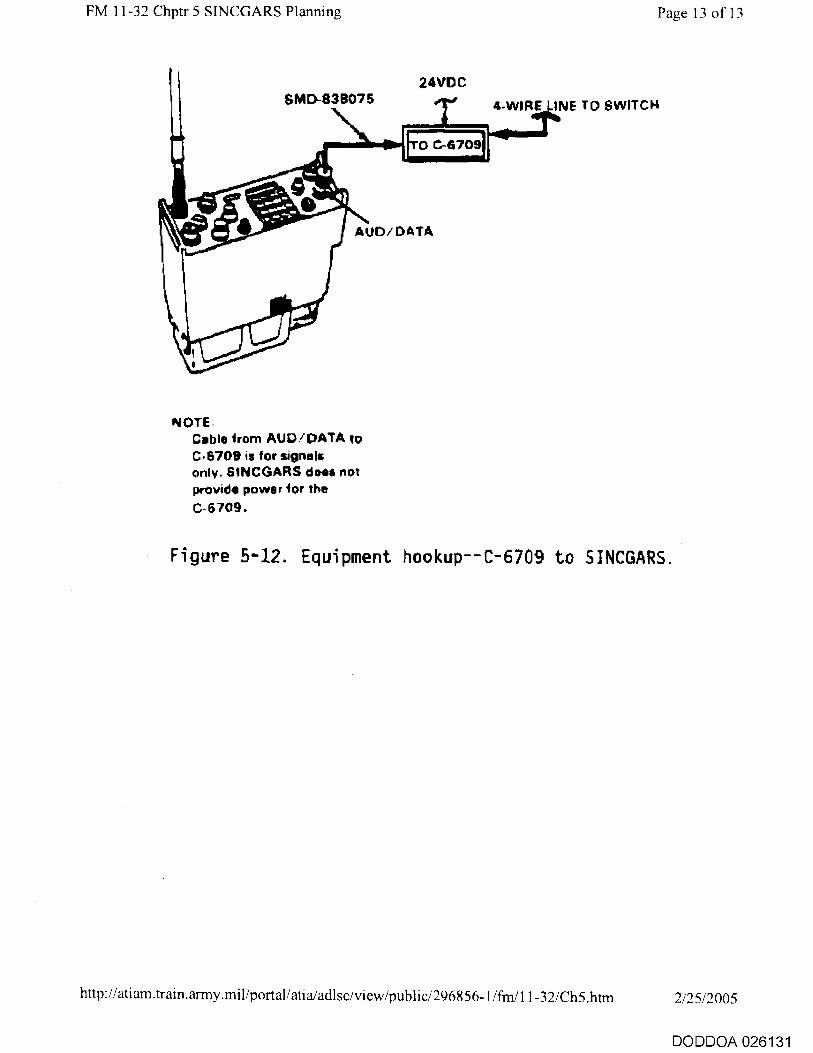
FM 11-32 Chptr 5 SINCGARS Planning Page 13 of 13
24VDC
4-WIRE LINE TO SWITCH
NOTE. Coble horn AUD/DATA to C•6709 is for signals only. SINCGARS does not provide power for the C-6709.
Figure 5-12. Equipment hookup -- C- 6709 to SINCGARS.
http://atiam.train.army.mil/portaliatia/adlsciview/public/296856-1/frn/11-32/Ch5.htm 2/25/2005
DODDOA 026131

FM 11-32 Chptr 6 IHFR Page 1 of 5
Chapter 6
IHFR
6-1. System Description
IHFR, like SINCGARS, is a modular design radio. The components that make up the different radio configurations are similar from set to set. Fielding for IHFR is different from SINCGARS in that IHFR is a replacement system and a new capability system. It replaces the stand-alone AN/GRC-106 and the AN/PRC-70/74. It will also be used in combat, CS, and CSS Armywide. When using IHFR, all transmissions should be secured with an approved cryptographic system.
6-2. Components
a. The primary component of IHFR sets is the RT-1209. Figure 6-1 shows the RT and the amplifier/coupler described below. It is an SSB radio that can operate in either the upper or lower sideband. It operates over the frequency range from 2 to 30 MHz in 100 Hz increments. This makes it compatible with all currently fielded US and allied SSB radio systems. However, it is only compatible when operating in the upper sideband mode. IHFR is not directly compatible with older generation AM double sideband (DSB) radios. An experienced AM-DSB radio operator can receive the SSB signal using special procedures specified in FM 24-18. IHFR accepts input of voice and data rates up to 2,400 bps when used with appropriate data modems. The RT can be set for RECEIVE ONLY to prevent unintentional transmissions during radio listening silence.
WHIP ANTENNA
RECEIVER/EXCITER IRT-1209)
AMP/COUPLER CAM-13374)
BATTERY ANDSET (H-250 or H-189)
Figure 6-1. RT-1209 and amplifier/coupler.
http://atiam.train.army.mil/portal/atia/adIsc/view/public/296856-1/fin/11-32/Ch6.htm 2/25/2005
DODDOA 026132
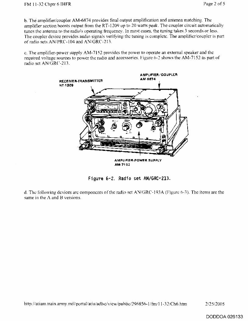
RECEIVER-TRANSMITTER Rt 1209
AMPLIFIER/COUPLER AM-6874
FM 11-32 Chptr 6 IHFR Page 2 of 5
b. The amplifier/coupler AM-6874 provides final output amplification and antenna matching. The amplifier section boosts output from the RT-1209 up to 20 watts peak. The coupler circuit automatically tunes the antenna to the radio's operating frequency. In most cases, the tuning takes 3 seconds or less. The coupler device provides audio signals verifying the tuning is complete. The amplifier/coupler is part of radio sets AN/PRC-104 and AN/GRC-213.
c. The amplifier-power supply AM-7152 provides the power to operate an external speaker and the required voltage sources to power the radio and accessories. Figure 6-2 shows the AM-7152 as part of radio set AN/GRC-213.
AMPLIFIER -POWER SUPPLY AM• 7162
Figure 6-2. Radio set AN/GRC-213.
d. The following devices are components of the radio set AN/GRC-193A (Figure 6-3). The items are the same in the A and B versions.
http://atiam.train.army.miliportal/atia/adlsc/view/public/296856-1/fm/11-32/Ch6.htm 2/25/2005
DODDOA 026133

mouPunNO BASE NIT-6112 /CIPD1S1A
AMPUFIEP.CONVERTER REO EIVER.TRA NIEPAITTEP AM-S 79/URC RT-1209/URC
FM 11-32 Chptr 6 IHFR
Page 3 of 5
ANTENNA COUPLER
POWER AMPLIFIER
c u-2044 /OR C-ISSA AM-A11411A/GRC- 1 93A
Figure 6-3. Radio set AN/GRC-193A.
(1) Antenna coupler CU-2064 is part of the high-power model. It provides the same function as the coupler section of the amplifier/coupler in the low-power version. The coupler automatically matches the impedance of the vehicular whip antenna.
(2) Power amplifier AM-6545A provides final output power. Output power is selectable between 100 and 400 watts. It provides visual indication of the radio's internal functioning, whether warming up, transmitting, or tuning.
(3) Amplifier-converter AM-6879 performs two functions. It amplifies the audio signal output to the external speaker, and is the modulator-demodulator for teletype signals. It accepts either 20 or 60 milliamp circuits making it compatible with mechanical and automatic teletype machines.
c. There are three mounting bases associated with I H FR-- one for the AN/GRC-213 and two for the AN/GRC-193A. The mounts provide a secure location for installation in tactical wheel and track vehicles.
f. The three antennas associated with the IHFR systems are the whip antenna (both manpack and vehicle mounted), the AN/GRA-50 doublet antenna, and the AS-2259 near vertical incident skywave antenna. The antennas are only mentioned here as part of the overall radio system. FM 24-18 and FM 24-19 describe the radiation patterns and uses for the various antennas.
6-3. System Configurations
http://atiam.train.army.mil/portal/atiaiadlsc/view/public/296856-1/fm111-32/Ch6.htm 2/25/2005
DODDOA 026134

FM 11-32 Chptr 6 IHFR Page 4 of 5
a. The IHFR system is designed around three versions. Of the three versions, one is manpack, one is a low-power set adaptable for manpack or vehicular use, and one is a high-power set strictly for vehicular installations. As stated above, the RT-1209 is a common component of all three radio sets. The remaining components of each set come from the devices listed above.
b. Manpack radio AN/PRC-104A (Figure 6-1) consists of the RT, amplifier/coupler AM-6874, antennas, and handsets. It replaces the manpack radio AN/PRC-70/74. The AN/PRC-104A provides 280,000 tunable channels and has automatic antenna tuning.
c. Low- power vehicular/manpack radio AN/GRC-213 (Figure 6-2) is used in a new role. It provides the tactical commander with an HF capability. It consists of the AN/PRC-104A radio with a vehicle mount and amplifier-power supply AM-7152. The three antennas described above are also components of the set. Neither the AN/GRC-213 nor the AN/PRC-104A should be used for data transmissions exceeding 1 minute in a 10 minute time frame. The low-power IHFR radio has a maximum key down time of 1 minute (ratio of 1 to 10, 1 minute transmission, 9 minutes receive). Any key down time more than minute can damage the radio.
d. The high-power vehicle radio AN/GRC-193A (Figure .6-3) replaces the stand-alone AN/GRC-106.
6-4. Ancillary and Secure Equipment
a. The remote associated with IHFR is the AN/GRA-39C. IHFR can be used with the ANNIC-1 vehicular intercommunications remote control with the VHF radios.
b. The KY-65 and the KG-84/KW-7 are the only encryption devices available for securing IHFR voice and data. The advanced narrowband digital voice terminal (ANDVT) MINTERM (Figure 6-4) is the new system for securing voice and data transmissions. The MINTERM replaces the KY-65 currently used with IHFR.
http://atiam.train.army.mil/portal/atia/adlsciview/publie/296856-1/frn/11-32/Ch6.htm 2/25/2005
DODDOA 026135

FM 11-32 Chptr 6 IHFR
Page 5 of 5
Figure 6-4. ANOVT MINTERM (KY-99).
http://atiam.tram.army.mil/portal/atiaiadlsc/view/public/296856-1/frn/11-32/Ch6.htm 2/25/2005
DODDOA 026136

FM 11-32 Chptr 7 CNR Frequency Management Page 1 of 7
Chapter 7
CNR Frequency Management
7-1. Overview
The term "battlefield spectrum management" refers to managing electromagnetic spectrum resources to support telecommunications (including weapons systems) and EW requirements. This management includes allocating and assigning generating frequency resources and distributing the variables for FH radio systems. The items for management include frequencies, TSK variables, net identifiers, COMSEC variables, and time. International agreements determine frequency allocations. COMSEC variables are controlled in accordance with TB 380-40. This manual supplements those agreements and regulations for FH radio systems. TSK variables, net identifiers, time, and assignment of frequencies to hopsets are distributed at the discretion of the corps and division communications planners. However, equipment parameters impose some constraints on the distribution schemes for TSKs, net identifiers, and frequency allocations to hopsets (particularly for HF systems).
7-2. Frequency Allocations
a. The table of frequency allocations is an international agreement under the control of the International Telecommunications Union (ITU). The table provides frequency allocation by type of service. Each nation can modify the table or reallocate bands as needed inside their international boundaries. The battlefield spectrum manager (BSM), with the signal planning element, uses the BECS computer to assign frequencies to hopsets for HF and VHF radio networks. The computer mathematically manipulates the frequencies based on the restrictions the manager enters into the data base. The computer develops hopsets by correlating the restrictions with available frequencies.
h. Many subscriber duties and unit missions (for example, corps or division commanders and cavalry regiment) require travel through several different areas on the battlefield. Those same individuals or units require constant communications as they move across the battlefield. The BSM assigns a theater level hopset and TSK which provides mobile users effective communications and maintains legal frequency use.
(1) The common hopsets are determined from the frequencies available for use throughout the entire area of operation for the senior command. For example, the corps commander requires communications in the corps area and each of the division areas. The corps spectrum manager receives listings of frequencies to be used in each area. The spectrum manager compares the lists and pulls out frequencies that are common to all areas under corps control. These frequencies are used to generate corps common hopsets.
(2) The hopsets for division must make maximum use of the available frequency resources. The division resource includes the corps common hopset and any special purpose hopset, which may rarely be required. The division spectrum manager determines the division hopsets and any special purpose hopset. The brigade does not have a spectrum manager; however, both brigade and battalion signal officers have an obligation to manage their network composition.
(3) The BSM assigns the maximum number of frequencies available in the area of operation and spreads the frequencies in the hopsets across the widest possible band to optimize ECCM capabilities. Spreading the frequencies across the spectrum is more important than increasing the
http://ati am.train.army.mil/portal/ati a/adlsc/vi ew/public/296856-1/frn/11-32/Ch7.htm 2/25/2005
DODDOA 026137

FM 11-32 Chptr 7 CNR Frequency Management Page 2 of 7
total number of frequencies available. Fifty frequencies spread from 30 to 88 MHz is more effective than 200 frequencies from 30 to 35 MHz. Chances are slight that the jammer can cover the 58 MHz range or even a small portion of it with sufficient power to disrupt communications; however, a jammer could barrage jam the entire 5 MHz range.
c. HF networks require special considerations in frequency assignments. HF antenna tuning limits the range of frequencies allowed. The spectrum manager must consider the required circuit quality for the information to be passed. The farther the frequencies are dispersed from the center or tuning frequency, the poorer the quality of the circuit. This is especially true for skywave transmissions since frequency affects the skip range. Even a small change in frequency can alter the path the signal takes through the atmosphere. (FM 24-18 and FM 1 1 -64 cover radio wave propagation.) The spectrum manager must determine whether signal quality or antijam capability is most important when assigning frequency hopsets.
(1) High priority networks that pass critical information require high accuracy (whether voice or data). Such networks must use hopsets restricted to a narrow distribution of frequencies.
(2) Networks that are subject to high level jamming require maximum dispersion of frequencies in the hopset. The main drawback of wide dispersion of frequencies is poor system quality. The poor quality is due to lower radiated power from the antenna when the hops are on frequencies at the specified limits of the bands.
d. The NRI hopset scheme in Chapter 5 requires using only two hopsets throughout the corps area. The hopsets are specified by the corps spectrum manager, coordinated with the corps signal brigade, and included in the SOI data transferred from the corps to all divisional elements. The remaining hopping variables (TSK, net identifier, and time) arc identical for all the NRI networks. This allows transient users access to the NRI system using a single preset position across the corps area.
c. Cue and manual frequencies for SINCGARS networks must be designated in the SOI for each time period. The cue frequency is assigned to a 50 kHz channel to allow older generation and allied radio users access to the network. The cue frequency must also be limited to the VHF band from 30 to 75.95 MHz. The manual frequency should he assigned to 25 kHz channels from 30 to 87.975 MHz. The BECS computer automatically assigns both frequencies along with a hopset using the above criteria. Table 7-1 shows the three items listed for each time period. The first is the hopset designation followed by the cue and manual frequencies. The radio operator must enter all three variables into the radio for each time period. If the operator wants to enter a network he is not normally in, the cue frequency is used.
Table 7 - 1. SOI extract for SINCGARS network.
UNIT 1 2 3 4 5
52D MECH Div F250 F378 F176 F234 F437 MAN 52.325 47.275 39.925 62.875 79.925 CUE 72.500 53.250 54.850 48.350 47.150
52E) INTEL F498 F265 F250 F378 F265 MAN 83.275 61.125 82.725 42.825 72.825 CUE 45 500 71.000 62 050 34.250 55.800
f. Planning must include provisions for interference between colocated radios of the same type (for
http://atiam.train.army.mil/portal/atialadIsc/view/public/296856-1/finil 1-32/Ch7.htm 2/25/2005
DODDOA 026138
FM 11-32 Chptr 7 CNR Frequency Management Page 3 of 7
example, single-channel to single-channel radios). The potential for interference exists in the single-channel nonhopping mode and the FH mode. Single-channel frequency assignments must comply with Table 5-1. The potential for interference increases as the total number of colocated FH networks increases. For example, a brigade CP may operate in up to six different FH networks at a time. The hopsets should maximize use of frequencies separate from any of the colocated networks. This can he planned, but it requires knowledge of network structures and which networks are colocated. The spectrum manager must work closely with the G3/S3 to minimize the effects on colocated networks.
g. Planning must consider possible interference between unlike radios (SINCGARS and MSRTs). SINCGARS can be programmed to lock out certain frequencies from the hopset. Neither BECS nor the system control center (SCC) can engineer frequency use for both systems at the same time. The spectrum manager must plan the MSRT/radio access unit (RAU) frequencies with the SCC and enter them into the BECS terminal as lockout sets. Frequency interference between the radio systems is minimized, particularly the cosited systems.
h. The SCC provides frequency management to ensure no frequency conflicts exist between the RT-1539 (MSRT/RAU) and CNRs operating in the same area. This management applies only to VHF CNRs operating in the nonhopping mode. The SCC does not develop the hopping variables used by the SINCGARS. The VHF assignments are broken into protected channels and common (shared) channels. Protected frequencies are primarily assigned to radio nets which cover a large terrain area. This includes MSE MSRTs and division command nets.
i. Separate data network hopsets may he allocated to increase reliability of information when interference causes too many errors in data transmissions. This does not mean that the hopsets have sole use of all frequencies in the hopset.
j. Equipment constraints limit the total number of net identifiers to 1,000 (000 to 999). Numbers 000 through 099 are reserved for joint/theater units, 100 to 299 are for corps units, and the remainder (300 to 999) can be used by the divisions as the spectrum manager and division signal officer see fit. The net identifier assignments should he coordinated to simplify building the SOI data base.
(1) Net identifier numbers are assigned in the order they are entered into the BECS data base. Once assigned, net identifiers do not routinely change. Networks appear in current SOIs from higher echelon to lower. The type and number of networks vary little from one division to the next.
(2) The BECS data base manager develops reuse plans for the net identifier variable across the corps area. The simplest plan is to develop a single listing in the SOI for a type division and leave open net identifier assignments for variation between different division organizations. The divisional networks are numbered the same for type networks throughout the corps.
7-3. TSK Management
a. The current distribution scheme for TSK variables uses the same key for the entire corps. If operations require units to travel into another corps area, the corps in place must transfer the new TSK to the transient unit. The signal staff officer (SSO) or spectrum manager in the transient unit coordinates with the other corps SSO or spectrum manager to obtain the correct TSK.
(1) The TSK must be changed every 90 days. The TSK must be physically loaded into the radio from a fill device. The TSK variable may he transferred to the VINSON device over-the-air and
http://atiam.train.army.mil/portal/atia/adlse/view/public/296856-1 / in/11-32/Ch7.htm 2/25/2005
DODDOA 026139

FM 11-32 Chptr 7 CNR Frequency Management Page 4 of 7
then physically loaded into the radio from the VINSON. (See TM 11-5820-890-10-1 for additional information.) Users are prohibited from transmitting variables over nonsecure radio links.
(2) Fill devices should he loaded with the current and the succeeding TSK variables for quick transfer in case of compromise. The non-ICOM SINCGARS radio can be filled with only the current and succeeding variables. The ICOM SINCGARS radio can hold up to six TSK variables.
(a) Maneuver units fill the positions with the TSK of the networks they are required to communicate with. In most cases, this is the corps common TSK for all six positions. Units located on the corps boundary load the TSK of the adjacent unit into position 5 with the adjacent unit hopset.
(b) Units that require communications with multiple echelons above corps (EAC) use the following assignments for the six presets:
■ Position 1 - Local/division.
■ Position 2 - Division/corps.
■ Position 3 - Theater Army.
■ Position 4 - Joint.
■ Position 5 - Scratch location.
■ Position 6 - TSK remote keying variable (RKV).
Positions 5 and 6 are used for remote keying of the TSKs over the radio link. The operators follow the same procedure used to remote key VINSON COMSEC variables. Ground units that require communications with tactical aircraft, such as air traffic control or forward air control units, use position 4 as the common TSK location.
h. The COMSEC TEK for VINSON and ICOM SINCGARS is the same as the X encryption keys used by the KY-68 DSVT and KY-90 NRI device. The keys are corps common and distributed by the corps COMSEC manager through the MSE system. KEK remains common only to the local network. The NCS capability to selectively remote key individuals is retained to protect the network should keyed equipment be captured. Remote key procedures for the new systems are the same as those used with the VINSON devices.
7-4. Time Management
a. Zulu or GMT is the time reference for all networks. This provides a standard time that allows the simplest access to any network. The network NCS or the net timing station (NTS) manages time.
h. SINCGARS can send the NCS time reference to the network subscriber over the radio link. This allows some leeway in time variation on initial loading. If the subscriber cannot enter the network, he has the NCS send the correct time data. Also, anytime the difference is between 4 seconds and 59 seconds, he must use LNE to access the net. Finally, SINCGARS can store a delta time difference between its clock time and that of other networks up to 59 minutes apart in the preset positions. By
http://atiam.train.army.mil/portal/atia/adl sciview/public/296856-1/fm/ 1 1-32/Ch7.htm 2/25/2005
DODDOA 026140

FM 11-32 Chptr 7 CNR Frequency Management Page 5 of 7
using GMT as the time reference, all networks will be well within that time limitation.
7-5. BSM Responsibilities
a. One of the BSM'S primary duties will he controlling and monitoring time for the commander. The corps and division BSMs establish authorized frequency assignments for their respective echelon and for subordinate units. The BSM is responsible for deconflicting frequency interference within his unit. He should he actively involved in the overall communications plan to ensure frequency plans and allocations meet the mission requirements at all levels within the command.
b. The frequency manager starts the planning process by compiling the frequency requirements from the subordinate units. He combines the subordinate unit requirements with those of his echelon and forwards the request to the next higher headquarters. The combine and forward process continues upward to the unified command authority in the theater of operations. The J6 joint communications officer deconflicts frequency use plans and allocates frequencies back down to component service BSMs.
c. The frequency allocations are divided at corps and division echelons. The BSM office assigns frequencies based on criteria similar to that used to develop the initial request. The most important criteria are--
• Network priority.
• Equipment in use.
• Equipment separation.
• Retransmission requirements.
• Frequency use restrictions.
d. The corps and division battlefield spectrum management offices develop SOI. The two offices work separately but in close coordination to produce the entire corps SOI.
(1) Previously, the NSA or the battlefield spectrum management office at corps and division produced SOIs. The frequency manager compiled all the SOI information, applied the above criteria, and sent the package to NSA for production. Once BECS is fielded, it will allow the manager to accomplish all the tasks at the home station and make changes to the end product easily and quickly. BECS increases the battlefield spectrum management office's efficiency in producing SOIs, distributing FH variables, and resolving interference problems.
(2) The corps battlefield spectrum management office produces and distributes the corps headquarters, corps units, and division command level 501 information. The corps frequency manager assigns restrictions to frequencies for hopset development. He determines the corps common hopsets, assigns hopsets to the corps units, and allocates frequencies to the divisions for use in their hopsets. The corps SOI information is transferred to the divisions for inclusion in their SOI data bases.
(3) The division battlefield spectrum management office incorporates the corps and division command level SOI information into its data base along with subordinate unit information. The
http://atiam.train.army.mil/portal/atia/adIsciview/public/296856-1 /fm/1 I-32/Ch7.htm 2/25/2005
DODDOA 026141

FM 11-32 Chptr 7 CNR Frequency Management Page 6 of 7
division frequency manager assigns network restrictions and frequencies in BECS to develop the hopsets for division use. Once all information is in the data base, the division SOI is produced and distributed to the division and subordinate units.
e. The BSM is responsible for identifying the frequencies used by the MSRTs/RAUs in his area of operation. The corps battlefield spectrum management office under the G6 corps signal officer handles the coordination. The corps battlefield spectrum management office should have direct access to the SCC which assigns the MSRT/ RAU frequency pairs (up to 96 pairs). The BSM compares the frequency pairs in use for a given time period and enters those into BECS as lockout sets for FH radios.
f. Interference resolution is handled at the lowest level possible. However, the battlefield spectrum management office has final jurisdiction in solving interference problems. The battlefield spectrum management office can solve interference on networks by--
• Requesting assistance from MI units in determining the source of the interference.
• Advising relocation of the affected network.
• Advising the user to work through the interference.
• Providing new frequency plans.
g. The battlefield spectrum management staff coordinates with all components operating in their area including airspace. Air Force, Navy, and Army aviation assets must be included in the planning to control all aspects of the AirLand Battle concept.
7-6. BSO Responsibilities
a. The signal officer assigned to combat brigade and battalion units has many duties and responsibilities. Those duties include all aspects of signal related topics that affect the maneuver unit's ability to fight and control the battle. FM 11-50 outlines the basic duties of the BSO, communications platoon leader, and communications chief. The responsibilities in FM 11-50 are still valid with the addition of the particular tasks associated with BECS and FH systems. This chapter addresses the specific tasks associated with the BECS computer, SOI tailoring, and distribution of the FH variables and SOI data.
b. The BSO's responsibility as a communications training developer and manager has increased importance with the fielding of new automated systems. FH radios present challenges in operator and planner training. The BECS computer gives the BSO an automated system for real-time SO1 data and network management. As the primary BECS operator, the BSO--
• Develops and submits initial SOI data base information and subsequent revisions to higher headquarters.
• Determines network structures for the unit with the S3.
• Coordinates with higher and adjacent headquarters for SOI and FH variables when the unit must operate outside normal channels.
• Develops distribution schemes for users in the unit networks.
http://atiam.train.army.mil/portal/atia/adlsc/view/public/296856-1/fm/11-32/Ch7.htm 2/25/2005
DODDOA 026142

FM 11-32 Chptr 7 CNR Frequency Management Page 7 of 7
• Develops operator training plans for EN remote fill procedures.
c. The EN can be filled with complete or partial SO1 data from the corps or division down to platoon level. The BSO must coordinate with the unit S3 to determine which subscribers receive what portions of the SOI. This is called tailoring the SOI for specific user missions. By tailoring, the SOI units can develop electronically what was called the SOI extract. The BSO fills the subscriber EN with the required information to minimize the consequences should the EN be compromised.
d. BECS at the brigade and separate battalion level also gives the BSO a quick method of developing an SO1 for task force organization. The BSO determines the units assigned to the task force from the mission operations order. Then, he uses the BECS terminal to pull out the call signs of those units and stores them in a separate file for recall.
e. The BSO is responsible for control and distribution of FH variables and SOT materials. BECS centralizes that control and simplifies distribution to the individual users in the unit. It allows the BSO to selectively fill subscriber ENs, locally and remotely, with the required SOI data. Since the BSO or a designated representative is the primary BECS operator, he has direct control over initial information loaded into each EN. The BSO also controls who the SOI is given to in the basic generation unit (BGU) to BGU transfers (such as brigade to battalion distribution). This provides the BSO centralized control of distribution and revision of SOI data in his unit.
f. The signal personnel authorized to battalion and brigade units has decreased with most equipment becoming user-owned and -operated. This places another burden on the BSO and communications chief to monitor communications procedures in their unit. Signal personnel will no longer operate the majority of communications equipment. The primary users are the combat arms, CS, and CSS personnel throughout the battlefield. This increases the importance of a good training plan. The training plan ensures the general- purpose user (GPU) is familiar with operator procedures for all new pieces of equipment. Initial planning must include network activation and remote keying operations as well as remedial actions peculiar to FH radios.
http://atiam.train.army.mil/portal/atia/adIsc/view/public/296856-1/frn/11-32/Ch7.htm 2/25/2005
DODDOA 026143

FM 11-32 Chptr 8 BECS Page 1 of 6
Chapter 8
BECS
8-1. System Description
a. BECS is a common computer-based software package. The communications planner uses BECS to design, develop, and produce the SINCGARS variables and SOI material. The BECS terminal can be used to manipulate unit SOI data bases to produce outputs in electronic and hard copy formats. The fielding of data storage devices makes hard copy SOI obsolete and eases the operator's burden of carrying and using the paper SOI .
b. BECS is being fielded from corps through brigade and separate maneuver battalion levels. Corps and division signal planning sections use BECS to generate the SOI and FH variables for their own levels and subordinates. The brigade and battalion units use BECS to reproduce SOI documents and ECCM fill for use at their respective levels.
8-2. Components and Capabilities
a. The current BECS terminal is designed around three primary components:
• BGU.
• Printer.
• Fill devices.
With the complete fielding of the EN, the terminals at brigade and battalion levels will be used primarily as storage and transfer devices for the FH variables. Until that time, BSOs will use them to produce paper copy SOls.
(1) BGU. The AN/GYK-33 BGU is a small microcomputer with a self-contained screen and disk drive. The NSA developed the operating system software that produces the SOI and FH variables. The system may eventually be transferred to the Army Command and Control Computer System (ACCCS) for use in field situations.
(2) Printer. The dot matrix printer can produce a paper copy of the SOI . It does not produce any of the variables for radio operation. The variables must be transferred to one of the fill devices available for the CNR system in use.
(3) Fill devices. The two fill devices associated with CNR systems are the MX-10579 and the EN. The MX-10579 holds the hopset, the net identifier, and the TSK variables. The current EN holds the same variables along with a complete or partial SOT and a common time reference. The follow-on data transfer device (DTD) being developed by the NSA will also hold the COMSEC variables required for secure operations with VINSON and the ICOM radio. The EN will be issued one per radio location for SINCGARS and IHFR radios. Multiple radio configurations or locations (such as CPs) will have one EN.
b. The BECS, as a self-contained system, is primarily used to generate, transfer, and store CNR
http://atiam.train.army.mil/portal/atia/adIsc/view/public/296856-1/fin/11-32/Ch8.htm 2/25/2005
DODDOA 026144

FM 11-32 Chptr 8 BECS Page 2 of 6
variables and SOI materials. It is also used to fill the various loading and transfer devices associated with CNR systems. The system generates five time periods of SOI data per computer run. The operator turns out as many time periods as required by requesting consecutive runs from the computer and storing the data on computer disks or printing out the files. The operator specifies the starting number of the time periods to generate the equivalent of a 30-day SOI using the consecutive runs. The BECS terminal locally generates variables for FH operation.
(1) Hopsets. Hopsets are generated from the list of allocated frequencies the BECS operator enters. Frequencies are classified by any restrictions on their use for areas or power levels available. The restrictions on frequencies are compared against any restrictions on network usage. For example, a brigade command network requires use of high-power at all times. The command network is coded to restrict assignment of frequencies coded as low power only to the hopset. The frequency manager programs any restrictions for frequency use as it is entered into the data base. Frequencies can be entered into the BECS by using either discrete frequencies or lockout sets.
(a) With discrete frequencies, the frequency allocation list is fed into the computer one frequency at a time and is compiled in a frequency map.
(b) With lockout sets (applies to SINCGARS only), undesired blocks of frequencies or discrete frequencies are prohibited from use. There are two types of lockout sets--net definition and common lockout sets. Up to six net definition lockouts that correspond to the six preset channels can be programmed into the radio. Net definition lockouts specify groups of frequencies that are prohibited from use for the hopping sequence on a particular preset. Common lockout sets (total of eight available) specify frequencies that are simultaneously prohibited from use for all presets.
(c) Until either the BECS or the SCC is modified to manage SINCGARS and MSRT/RAU frequencies, the MSRT/RAU frequencies have to be entered as lockouts for the radio.
(2) Net identifiers. The corps/division BECS operator manually inputs net identifiers in the master net list. The networks are numbered consecutively starting at the point the computer operator specifies. Net identifiers will be allocated per echelon as follows: 000 to 099 for theater and above, 100 to 299 for corps, and 300 to 999 for division.
(3) Cue and manual frequencies. The computer assigns cue and manual frequencies for each network in the data base for each time period. It automatically assigns 50 kHz channels for cue frequencies and 25 kHz channels for manual frequencies.
(4) TSK variables. The corps TSK is generated at the corps spectrum management office and is transferred down with the corps SOI information to the division. The terminals at division and below are used as distribution systems for the TSK and the remaining SOI information.
(5) Single-channel frequencies. Single-channel network frequencies can be planned using the network and frequency restriction capability of BECS. It uses a modified type of Boolean logic to match requirements to restrictions. The operator sets up his own restrictions list to match whatever the unit missions require. Single-channel retransmission frequencies are automatically assigned frequencies a minimum of 10 MHz apart.
(6) Data networks. Data networks are not planned for automatically. If separate hopsets are required to provide interference-free networks for data, they must be listed as a separate network
http://atiam.train.army.mil/portal/atia/adlse/view/public/296856-1/ m/11-32/Ch8.htm 2/25/2005
DODDOA 026145

FM 11-32 Chptr 8 BECS Page 3 of 6
in the data base. Additionally, they must be coded with restrictions to provide the sole user frequencies necessary for clear transmissions.
(7) Call signs, suffixes, additional identifiers. The BECS produces randomly assigned call signs, suffixes, and additional identifiers for five time periods. The call signs developed are in accordance with JANAP 119 and ACP 100 standards.
(8) Challenge and password. The BECS generates a challenge and password (or sign and countersign) for each time period in the SOI.
(9) Pyrotechnics and smoke. The data base must specify the pyrotechnic and smoke signal meanings desired for unit operations. The BECS assigns a different pyrotechnic or smoke signal for the designated meanings in the SOI on a random rotating basis.
8-3. Software Management
a. The SOI data base is produced at the division and corps level to ensure all units within the organization are included. Although the SOI document is produced at the highest level, it is developed from the lowest unit up and is only as good as the input provided by the subordinate units. Subordinate units provide their network and subscriber input to the higher headquarters based on their particular missions and organization.
(1) Begin building the BECS data base with the unit's current SOI. It is the most likely complete source or nearly complete source of information for current operations. The current SOI can be updated quickly to reflect mission requirements and unit organization.
(2) If there is no current unit SOI, the BSO should coordinate with the G3/S3 for guidance on organization, network structure, and membership. The BSO should also poll the commanders, the communications chief, and other battalion or brigade officers to obtain general guidance and to identify any special requirements.
(3) The SOI information has to be supplemented with any changes due to task organizing. Previous SOI packages had to use spare call signs and frequencies if units were attached for specific missions. The BSO can now add the attached unit to the data base and include it in the main SOI as a subscriber. The BSO should review unit contingency operation plans for information regarding wartime requirements and SOI data.
(4) After compiling and organizing the information for networks, subscribers, and signal devices, the BSO forwards the data to the next higher signal planning section. The process is repeated up to the division signal office where all the divisional requirements are compiled, and the BECS data base is programmed into the computer. Corps units follow the same process up to the corps signal office, where the corps SOI data base is developed.
(5) The corps and division data bases are developed separately and remain separate. The two echelons exchange SOI information after the SOI is developed at their respective levels. The newly acquired data base is then processed via the data base merge function provided by BECS. Merging can only be accomplished one time with any one data base.
b. Modem communication systems provide easy methods for transferring digital information or codes from one device to another. The SOI data and FH variables are no exception. The data can be transferred
http://atiam.train.army.mil/portal/atia/adlsc/view/public/296856-1/fin/11-32/Ch8.htm 2/25/2005
DODDOA 026146

FM 11-32 Chptr 8 BECS Page 4 of 6
from BECS terminal to BECS terminal; BECS to EN; or EN to EN. Additionally, the information can pass over wire, radio, or by computer disk. The method used depends on time constraints and available equipment.
(1) If time is not a factor, the information can be stored on a computer disk and hand-carried to the required units. With a computer disk, there is a permanent record and data accuracy is guaranteed. However, there are disadvantages:
o A separate disk must be used for each subordinate.
o Time is required to courier the disk.
o Computers must use the same disk size and operating system.
(2) The second method of passing information from one BECS terminal to another is over a direct data link computer to computer. This can he over any number of different mediums, such as radio or wire links. The connection can be secured by any of the current inventory digital data encryption devices (for example, KG-84, KY-57/58, or KY-68). Figure 8-1 shows the connections through KY-68s and the switched ACU network. Figure 8 - 2 shows the switched land-line network extended using the NRI system as part of the data link. A BGU interface (BGUI) unit is required in both cases to convert the computer signal to one compatible with the transmission equipment. Advantages of data transmissions are as follows:
o Many subordinates can be filled at the same time.
o Information can be transferred quickly (in only minutes).
BGUI
KY-68 BGU I
Figure 8-1. BGUI/KY-613 remote distribution.
http://atiam.train.army.mil/portal/atia/adlsc/view/public/296856-1/fm/11-32/Ch8.htm 2/25/2005
DODDOA 026147

FM 11-32 Chptr 8 BECS Page 5 of 6
eGUI KY-66
Figure 8- 2. EGUI/KY-90 remote distribution.
(3) After the SOI data has been distributed to the various headquarters, the EN is used to disseminate the information to the system users. The EN is the common fill device for all Army systems, including SINCGARS, EPLRS, and JTIDS. The EN can be filled from a BECS terminal or from another EN. The fill can be done locally or remotely over-the-air (either CNR or ACU).
(a) If done locally from the BGU, up to six ENs can be filled at the same time (Figure 8-3). EN to EN allows filling only one device at a time.
BGU
SGUI
EN1 EN2
EN3
EN4
EN5
EN6
EN
BGUI
BGU
Figure 8-3. Local SDI distribution.
http://atiam.train.army.mil/portal/atia/adIsc/view/public/296856-1/fm/11-32/Ch8.htm 2/25/2005
DODDOA 026148

EN
FM 11-32 Chptr 8 BECS
Page 6 of 6
(b) Over-the-air fills require the transmitting station to identify the recipient by user number before transmission. The transmitting terminal can earmark from 1 to 16 ENs to receive the new SOI information (Figure 8-4).
Figure 8-4, Remote SOI distribution.
(4) The SOI data should never be transmitted over nonsecure circuits. The link may be either bulk encrypted by the system devices (KG-27) or end-to-end encrypted by data encryption devices (VINSON KG-84, KY-68) before transmission.
http://atiam.train.army.mil/portal/atia/adlsc/view/public/296856-1/frn/11-32/Ch8.htm 2/25/2005
DODDOA 026149

FM 11-32 Chptr 9 Special Siting Considerations Page 1 of 6
Chapter 9
Special Siting Considerations
9-1. Overview
The modern C 2 system uses multiple colocated radios to provide an effective communications system. The potential exists for a number of different radio sets or configurations to interfere with each other. This chapter provides procedures to minimize detrimental effects of colocated systems operating in the same frequency ranges. The interference problem is broken down into three categories:
• IHFR to IHFR.
• SINCGARS to SINCGARS.
• SINCGARS to MSRT/RAU.
IHFR effects on SINCGARS or MSRT should be minimal since IHFR operates in a frequency band separate from the other two systems. The procedures discussed here are near-term measures to ensure successful use of all three systems.
9-2. Cosite Interference
a. Active management of three possible areas can minimize interference problems:
• Spectrum sharing.
• Antenna separation.
• Network time sharing.
The communications planners and the BSM control spectrum sharing. The installer and system users directly control antenna separation and time sharing.
(1) Spectrum sharing has different parameters in each area depending on the equipment characteristics, propagation paths, and system quality. BSM is an on-going analysis process. HF sounders determine usable HF frequencies and user feedback determines quality of VHF networks. The BSM has overall responsibility to deconflict any interference problems that arise from colocated systems. He has a frequency manager and the BECS computer to assist in arriving at that goal. The chapters on SINCGARS and IHFR cover the specific criteria for frequency management of like cosited systems.
(2) The question of when to use antenna separation and time sharing is situationally dependent and at the discretion of the individual commands. The primary concern of field users is passing of
C2 information most accurately and in minimal time. Time sharing requires active management on the part of each network NCS/NTS. The ideal situation is when both NTS radios are at the colocated site. However, that will be the exception in most cases. The networks must operate as directed networks to provide the control necessary for a time shared scenario. This is true for all
http://ati am .train.army.mil/portal/atia/adl sc/view/public/296856-1/frn/11-32/Ch9.htm 2/25/2005
DODDOA 026150
FM 11-32 Chptr 9 Special Siting Considerations Page 2 of 6
types of single-channel radio networks (IHFR or SINCGARS).
b. Antenna separation followed by time sharing is the preferred method to minimize interference in all three categories. Using the two methods depends on time constraints versus information volatility. That is, if the CP is immobile for long periods of time (a field hospital or units in defensive positions), the users install the systems with maximum antenna separation. In highly mobile CPs (a battalion CP during offensive operations), time does not permit using of remoting kits. Users must time share to retain use of both networks.
9-3. Symptoms and Solutions
The key to solving interference is identifying its source. FM 24-18 describes the steps an operator takes to identify the source of the interference. If the interference is from an external source, the operator submits a meaconing, intrusion, jamming, and interference (MIJI) feeder voice template report in accordance with FM 24-33 or FM 24-35. Cosite interference is defined to occur while both systems are in operation--either transmitting or receiving. The following remedial measures assume the operator has ruled out external interference and has identified one or several colocated radios as the source. The procedures listed here may he used in advance to minimize interference during initial installation of the radio systems.
a. IHFR to IHFR. The primary cosite problem with IHFRs will he in CPs that simultaneously monitor and transmit on several HP networks. There are few mobile radio sets that operate two HF radios at the same time.
(1) Frequency selection is done by the BSM at corps or division. It is crucial that the BSM be aware of which networks will be operating in colocated sites. This can be accomplished through direct coordination with the assistant corps signal officer (ACSO) or the ADSO and radio officer as appropriate. Frequency selection for short-term antijam (STAJ) networks must consider the operating range versus system quality.
(2) Remoting the antenna or the radio set can accomplish antenna separation. No remote siting capability exists for the AN/PRC-104( ) or AN/GRC-213( ).
(a) Antenna separation from the radio for the manpack and low-power vehicular models is limited to the 45.5 meters (150 feet) of coaxial cable supplied with the radios. Increasing the cable length with the supplied cable degrades the signal and reduces the system's range. Replacing the supplied cable with low loss RF coaxial cable can increase the distance. TC 24-24 lists the cables used for extended ranges.
(h) The high-power radio set can he remoted up to 61 meters (200 feet) by using the tactical antenna remoting kit. The remote kit moves the antenna coupler CU-2064 to the remote site to provide additional antenna separation. Remoting the high- power set requires two cables--the RF coaxial cable and the control cable for the antenna coupler. Figure 9 - 1 shows the remote configuration and necessary cabling. Refer to TM 11-5820-924-13 for complete installation instructions. The remote site must be grounded for proper operation and safety reasons.
http://atiam.train.army.mil/portal/atia/adlsc/view/public/296856-1/fin/1 1 -32/Ch9.htm 2/25/2005
DODDOA 026151

FM 11-32 Chptr 9 Special Siting Considerations Page 3 of 6
Figure 9 - 1. Remote configuration and cabling.
(c) Another method of antenna separation is to remote the entire radio with remote control sets. The IHFR sets can be remoted up to 3.2 kilometers (2 miles) with the AN/GRA-39C radio control group. This method is easy to implement and gives full use of both systems. The greatest disadvantages of remoting the radio sets are as follows:
■ The setup and teardown time increases.
■ An operator must monitor the remote site.
■ The landline is not secure.
b. SINCGARS to SINCGARS. SINCGARS cosite interference can be divided into two separate cases: single-channel and FH. The single-channel case is solved by following the guidance in Chapter 5 for frequency versus antenna separation distance. Additional information on single-channel VHF radios can be found in FM 24-2. Operators can use the same equipment and procedures to remote single-channel as discussed below for FH networks. The FH network problem is slightly more complex to address for BSM. The discussion of SINCGARS FH interference is divided into the same three areas as IHFR problems: time sharing, spectrum sharing, and antenna separation. Time sharing applies the same as the IHFR system discussed above.
(1) The BSM at the division or corps signal planning element performs spectrum management. The cosited radios must use hopping variables that separate the receiving and transmitting frequencies to prevent radios from locking onto the wrong signal. The easiest way to manage the systems is to use different hopsets for the colocated networks. This does not necessarily prevent all frequency collisions unless the hopsets are designed as all mutually exclusive frequencies. The two systems may also use different TSKs to keep the radio signals separate.
http://atiam.train.army.mil/portal/atia/adlsc/view/public/296856-1/fm/11-32/Ch9.htm 2/25/2005
DODDOA 026152

H-290
GRA-39 WD-1
AM- n39
AS-3900
4 •••••••
141/69.1.:UO:FILI. 1'7
R7-1439 •
L8.1171
K 260
KV- 67
74/ 'RADIO AUDIO
J1
H-2150
Figure 9-2. AN/GRA-39.
FM 11-32 Chptr 9 Special Siting Considerations Page 4 of 6
(2) Antenna separation requires use of one of the following remoting systems available for VHF radios:
o AN/GRA-39 radio control group.
o SRCU (works with ICOM and non-ICOM).
o HYX-57 wire line adapter.
These systems are necessary to obtain a separation of 50 meters (165 feet) or more between colocated radios. The AN/GRA-39 (Figure 9-2) provides remote control up to 3.2 kilometers (2 miles) for a controlled area. It does not encrypt the signal on the wire line, so it must be physically secured. The other two devices (SRCU and HYX-57) provide secure capability over the wire. The SRCUremotes up to 4 kilometers (2.5 miles) and the HYX-57 (Figure 9-3) up to 6.4 kilometers (4 miles). If remotes are not available, the antennas can be separated up to 14.5 meters (45 feet) using one 0E-254 and associated cables or twice that distance if using two antennas. The last option is to place the colocated radios in different vehicles or areas of the CP to provide the physical separation required. The advantages of using remotes to separate antennas are as follows:
o Remotes are easy to implement.
o Cosite interference is minimized at CPs.
o The CP has full use of both systems.
The disadvantages are that setup and teardown times increase, and the problem still exists for mobile systems. Mobile subscribers must use spectrum sharing or time sharing as discussed above.
http://atiam.train.army.mil/portal/atia/adIsc/view/public/296856-1/frn/11-32/Ch9.htm 2/25/2005
DODDOA 026153

KY 57 HYX-57
RADIO: • KY
•
RADIO AUDIO • •
H-250 CX - 13072
HYX-67
RT-1439
AHD:TILL • RXMT J5
RADIO
LOCAL
KY - 5/
RADIO AUDIO
WIRE
LINE
(r"..))t1-250
FM 11-32 Chptr 9 Special Siting Considerations Page 5 of 6
REMOTE
Figure 9-3. Secure remote control HYX-57.
c. SINCGARS to MSRT/RAU. The potential interference between SINCGARS and MSRT/RAU radios is a special case and possibly the most severe of the three categories. The following procedures are near-term measures to minimize the interference until a technological solution can be implemented.
(1) Chapter 7 discusses spectrum sharing. The key is for the BSM to enter the MSRT/RAU frequency pairs with applicable guard hands into the BECS computer before hopset generation.
(2) Two remoting procedures provide antenna separation for the MSRT. The procedures are:
o Using the MSRT stand-alone field kit (SAFK).
o Remoting the DSVT via field wire.
The SAFK consists of components to dismount the radio equipment from the vehicle for remote operations. A separate power source is required. A 25-foot cable from the remoted radio set connects the antenna. The DSVT can be remoted from the radio using WF-16 field wire up to 250 meters (825 feet). Operations requiring that CPs he immobile for extended time periods will use remoting. The same advantages and disadvantages apply for remoting MSRTs as for SINCGARS.
(3) Operators must use time sharing to solve the interference between mobile MSRTs and SINCGARS. Operator procedures in time sharing now are slightly different than discussed for the two CNR systems alone. The MSRT transmits continuously from the time the call is initiated to the time the caller hangs up, unlike CNR systems that only transmit during key down. The interference to the MSRT is likely to be more severe than to the CNR system. In fact, the MSRT may release the call from too much interference, but the MSRT will retain affiliation with the RAU. The user must decide which call is more important if he receives calls on both systems at the same time. The user follows the guidance below based on his decision of which call is more important.
(a) If using the CNR and the MSRT rings, tell the CNR party to "Wait Out," then answer
http://atiam.train.army.mil/portal/atiadadlsc/view/publie/296856-1/fm/11-32/Ch9.htm 2/25/2005
DODDOA 026154
FM 11-32 Chptr 9 Special Siting Considerations Page 6 of 6
the MSRT. If the CNR is more important, get the number and return the MSRT call later. If not, complete the MSRT call. The CNR may be able to complete its call even through the interference from the MSRT, so the operator may not have to drop the call. The only disadvantage is that the MSRT continues to transmit as long as the DSVT is off hook.
(h) If using the MSRT and a call comes in on the CNR for the user, tell the MSRT party to hold on (do not hang up), then answer the CNR. If the MSRT is more important, tell the CNR party to "Wait Out." If not, complete the CNR call. If the interference on the CNR is too severe to pass accurate information, the user may have to hang up the MSRT and return the call later. Also, the MSRT may terminate the call automatically if the interference becomes too severe. Using short transmissions (less than 30 seconds) on the CNR will allow the MSRT to retain the call.
(4) If the situation requires many CNII calls or radio listening silence, the MSRT user can use call forwarding to reroute all his calls to a 'designated alternate. Determining the importance of incoming calls is a matter of command guidance and common sense on the user's part. A decision matrix in the unit SOP should address which system to use for situations versus the probable radio.
d. Solutions. Cosite interference is a matter of concern for planners and operators. The solutions depend on the situation and command emphasis. Solutions start from the initial allocation of frequencies and finish with the operator of the actual system on the ground. General guidance on solving the problem at the tactical level (assuming the BSM has done the best possible) is as follows:
• When time permits, use remoting kits to provide antenna separation.
• If necessary, use time sharing of the systems involved.
In all cases, the subscriber should use wire or the switched network as soon as it is available. This not only alleviates the interference problem. buti! .! is also the best ECCM technique any operator can use.
http://atiam.train.army.mil/portal/atia/adlsc/view/public/296856-1/fm/1 I -32/Ch9.htm 2/25/2005
DODDOA 026155

FM 11-32 Chptr 10 TACSAT Single-Channel System Page 1 of 13
Chapter 10
TACSAT Single-Channel System
10-1. System Description
a. Single-channel TACSAT is primarily a user-owned and -operated device that does not interconnect terrestrial systems. Its general use and configuration places it within the CNR portion of the communications architecture.
b. These terminals provide reliable, highly portable communications. They have minimum setup and teardown time and satisfy the need to communicate over extended ranges without regard to terrain interference. The system operates in the UHF hand between 225 MHz and 400 MHz. The terminals use a UHF satellite system (fleet satellite (FLTSAT) and Air Force satellite (AFSAT) space segments).
c. The Army terminals using Navy and Air Force space segments are the AN/MSC-64, AN/PSC-3, AN/VSC-7, AN/URC-101, and AN/URC-110. The AN/PSC-3 (Figure 10-1) is a manpack terminal carried by one operator. The AN/ VSC-7 (Figure 10-2) is a vehicle-mounted terminal which normally acts as an NCS and can control up to 15 subscribers. The AN/PSC-3 and AN/VSC-7 are the most common and will be used until new and lighter equipment is fielded. The AN/URC-10l and AN/URC-110 are manpack terminal transceivers that operate in the same band range (UHF), have the same characteristics for planning, and have similar technical specifications as the AN/PSC-3. Due to the unique similarities and limited quantities of systems, any reference to the AN/PSC-3 in this chapter will also include the AN/URC-101 and AN/URC-110.
http://atiam .train.army.mil/portal/atia/adlse/vi ew/public/296856-1/fm/11-32/Ch10.htm 2/25/2005
DODDOA 026156

MEDIUM-GAIN ANTENNA AND
CARRYING CASE
RT UNIT
FM 11-32 Chptr 10 TACSAT Single-Channel System Page 2 of 13
http://atiam.train.army.mil/portal/atia/adlsc/view/public/296856-1/fm/11-32/Ch10.htm 2/25/2005
DODDOA 026157

FM 11-32 Chptr 10 TACSAT Single-Channel System Page 3 of 13
AN/VSC-7 IAN/PSC-3( I WITH CONTROL CONVERTER)
HIGH- GAIN
ANTENNA
Figure 10-2. AN/VSC-7 TACSAT radio set.
10-2. Architecture
LOW-GAIN ANTENNA
a. The single-channel TACSAT architecture incorporates different users with different missions. Throughout all levels of war, TACSAT provides the range extension required to conduct effective operations. Single-channel TACSAT is specifically suited for the conduct of critical contingency operations. in contingency operations, the Army Force (ARFOR) commander defines the deployment of his task force by executing a forced entry operation in five phases (Figure 10-3). They are--
• Phase 1--Predeployment/crisis action.
http://atiam.train.army.mil/portal/atiaJadlsc/view/public/296856-1/frn/11-32/Ch10.htm 2/25/2005
DODDOA 026158
FM 11-32 Chptr 10 TACSAT Single-Channel System Page 4 of 13
• 'Phase 2--Deployment/initial combat
• Phase 3--Force buildup/combat operations.
• Phase 4--Decisive operation.
• Phase 5--Redeployment.
http://atiam.train.army.mil/portal/atia/adlsc/view/public/296856-1/frn/11-32/Ch10.htm 2/25/2005
DODDOA 026159

FM 11-32 Chptr 10 TACSAT Single-Channel System
Page 5 of 13
PH
AS
E 5
AIR
LA
ND
IB
EGH
S1 B
UIL
D- U
PI
MIS
SIO
N O
IEP
EN
DE
NT
HF
MU
LT
ICH
AN
NE
L
!MU
LTI
CH
AN
NE
L S
AT
CO
M
I M
SE
EQ
UIP
ME
NT
1 i
1 e
I
N4-
35 I N
-310
I I
I O
N B
OA
RD
AIR
CR
AFT
I
NA
NP
AC
KE
D S
ING
LE-
HF
ME
SS
AG
E
I SIN
GLE
CH
AN
NE
L R
AD
IOS
I C
HA
NN
EL
RA
DIO
S
I T
RA
FF
IC S
YS
TE
MS
4) ijj 4
J 41414 P
HA
SE
I P
ER
SO
NN
EL
DR
OP
I
PH
AS
E
EN
RO
UTE
HI- N
UT
ION
D
ER
N-H
OU
R
SE
QU
EN
CE
TIM
E I
IN
F
I ( H
OU
RS
) I
CO
MM
AS
SE
TS
IN
TR
OD
UC
ED
Ella
WO
1
D
NIN
I3V
M
so
r
II
PH
ASE
1 PL
AN
NIN
G P1
1
30
N 3r10
35
uriO
H-X
Figure 10 - 3. Forced entry mission in a joint service operation.
(1) Phase 1: The ARFOR establishes predeployment communications when the JCS warning order is received. Liaison officers are exchanged between the ARFOR, the other service components, the designated Commander in Chief (CINC), and possibly certain national agencies. Single-channel TACSAT, HF radio, and COMSEC equipment accompany these liaison officers.
http ://atiam.train.army.mi l/portal/ati a/adl sc/vi ew/publ ic/296856-1/fm/11-32/Ch10.htm 2/25/2005
DODDOA 026160

REPR
ESEN
TS 1
11NTS
tOR
WIIZ
ATID
PS
FM 1-32 Chptr 10 TACSAT Single-Channel System Page 6 of 13
(2) Phase II: ARFORs conduct the initial assault into the operational area. This assault is planned as a forced entry. However, the situation may allow uncontested air landing of forces. During phase II, communications consist of single-channel manportable radios. Joint radio nets are installed depending on the situation and the CINC's requirement. The baseline of joint radio nets the ARFOR headquarters may enter is listed below. In most cases, single-channel TACSAT terminals (Figure 10-4) are used.
Figure 10-4. Tactical architecture connectivity requirements for a forced entry mission in a joint operation.
o JTF Command/Transition (TACSAT voice) (HF voice) (FM).
http://atiam.train.army.mi l/portal/ati wadi sc/vi ew/public/296856-1/frn/11-32/Ch10.htm 2/25/2005
DODDOA 026161
FM 11-32 Chptr 10 TACSAT Single-Channel System Page 7 of 13
o JTF Operations/Intelligence (TACSAT data) (RATT).
o Joint Air Coordination (TACSAT voice).
o Joint Supporting Arms Coordination (FM) (HF).
o Linkup (FM).
o Embassy/DOD Interface (HF).
o Search and Rescue (HF or FM).
o Emergency NEO (HF or FM).
(3) Phase III: Force buildup involves moving combat, CS, and CSS elements into the area of operations. Constraints require that radios are light, reliable, and useable over extended distances. Units such as Special Forces groups and Ranger battalions deploy manpack TACSAT terminals. The physical environment does not restrict these deployments. The terminals are lightweight and compact, and they can be moved easily by one person. The NCSs are normally vehicle mounted. They are usually operated from a forward operating base by Special Forces groups or from a battalion headquarters by Ranger battalions.
(4) Phase IV and V: Operations involve sustaining, exploiting, and redeploying actions. Although multichannel TACSAT and MSE are deployed, single-channel assets are retained.
b. In all phases of forced entry, single-channel TACSAT use cannot be over emphasized. Manpack terminals can be easily deployed worldwide. A network can be a small deployment of three or four terminals with one NCS or a larger deployment with numerous NCSs. The ANNSC-7 (NCS) and AN/PSC-3 (backpack terminal) satisfy the real-time mission requirements of the following organizations.
• Special Forces.
• Ranger battalions.
• LRSUs.
• Atomic demolition team.
• Airborne/air assault divisions.
• Infantry division (light and heavy).
• Corps support command (COSCOM).
• Light infantry brigade (LIB).
10-3. Employment
a. Special Forces units use the AN/PSC-3s for group/detachment headquarters, forward operating bases,
http://atiam.train.army.mil/portal/atia/adlsc/view/public/296856-1/fm/11-32/Ch10.htm 2/25/2005
DODDOA 026162

FORWARD OPERATING
BASE 0 0
o o
o co
0 o
0
SP OPERATING
BASE
FORWARD OPERATING
BASE
FORWARD OPERATING
BASE
LON G-R ANG Ej200p-4000 KM 0
FM 11-32 Chptr 10 TACSAT Single-Channel System Page 8 of 13
and operational teams spread over extended distances. Command and control between major headquarters is primarily secure voice (Figure 10-5). All users at the Special Forces team level operate in a data burst mode using the OA-8990 data burst device. The special operations signal battalion can provide the following CNR capabilities:
AN/VSC-7
AN/PSC-3
Figure 10 - 5. Special forces employment.
(1) Provide two small signal extension nodes of which one service will be UHF satellite, HF, and VHF single-channel radio for voice, data, and facsimile communications.
(2) Provide a total of 14 quick reaction single-channel radio systems for C 2/liaison support that are deployable by ground, air, or amphibious assault.
b. The Ranger regiment/battalion command nets provide C 2 from regimental headquarters through company headquarters. They use secure voice and data burst in their operations (Figure 10-6).
http://atiam.train.army.mil/portal/atia/adlsc/view/public/296856-1/fm/11-32/Ch10.htm 2/25/2005
DODDOA 026163

FM 11-32 Chptr 10 TACSAT Single-Channel System
Page 9 of 13
Figure 10-6. Ranger battalion employment.
c. The LRSU net provides C 2 of long-range patrols deployed at extended distances. The sensitivity of the special surveillance missions performed by these patrols is satisfied by using manpack communication terminals with data burst transmissions.
d. The engineer atomic demolition net can coordinate and control releasing atomic demolition munitions (ADMs). The ADM nets operate secure voice and burst communications to pass release orders.
e. The airborne/air assault divisions use the AN PSC-3s primarily to provide a long-haul C 2 link between major headquarters during initial deployment. Once on the ground, those headquarters still requiring a communications link not available by LOS means or by multichannel satellite link will continue to operate by the AN/PSC-3 network. The primary mode is secure voice, though secure teletype (AN/UGC-74) is also used with appropriate interface devices.
E Selected infantry divisions (light and heavy) use the AN/PSC-3s to provide a long-haul C 2 link between major headquarters during initial deployment of a contingency operation. The primary mode is secure voice, though secure teletype (AN/UGC-74) is also used.
g. The contingency force CSS unit uses its AN/PSC-3s to facilitate communications for C 2 , operations, and logistics traffic between the CSS unit's emergency operations center and its deployed headquarters.
http://atiam.train.army.mil/portal/atia/adlsc/view/public/296856-1/frn/11-32/Ch10.htm 2/25/2005
DODDOA 026164
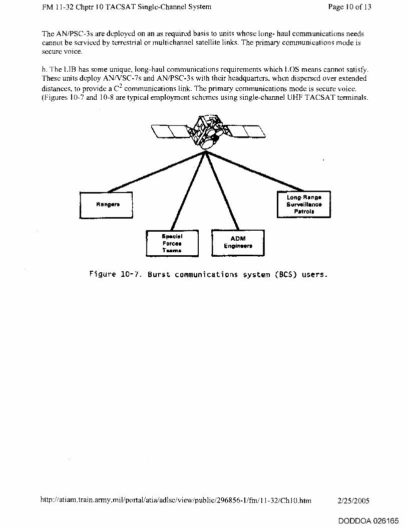
FM 11-32 Chptr 10 TACSAT Single-Channel System Page 10 of 13
The AN/PSC-3s are deployed on an as required basis to units whose long- haul communications needs cannot be serviced by terrestrial or multichannel satellite links. The primary communications mode is secure voice.
h. The LIB has some unique, long-haul communications requirements which LOS means cannot satisfy. These units deploy ANNSC-7s and AN/PSC-3s with their headquarters, when dispersed over extended distances, to provide a C 2 communications link. The primary communications mode is secure voice. (Figures 10-7 and 10-8 are typical employment schemes using single-channel UHF TACSAT terminals.
A ri%; IMM,re‘i■x%eWl■
411,'
Rangers
Special Forces Teams
Long-Range Surveillance
Patrols
ADM Engineer*
Figure 10-7. Burst communications system (BCS) users.
http://atiam.train.army.mil/portal/atia/adlsc/view/public/296856-1/fm/11-32/Ch10.htm 2/25/2005
DODDOA 026165

Airborne Division
Manger Regiment
■■•••••••■•=111
Light ,I Monti,/ Division
inii■■■■■■
Page I I of 13 FM 11-32 Chptr 10 TACSAT Single-Channel System
Contingency Air Aaseull Corps Division
Special Foroas
^eta6hmegt
Specie! F omits Group
light lofenov
r orjad r
COSCOso
Figure /D-8. Command and control secure voice users.
10-4. System Configuration
a. The AN/PSC-3 is a battery operated, highly portable, manpack TACSAT terminal. Additional power sources include the PP-6148( )/U power supply or the G-76(V) 1/G DC generator. It uses an RT-1402 unit that provides two-way communications in the frequency range of 225 MHz to 400 MHz. The RT functions in the satellite and LOS mode of operation. It can provide data or secure voice. The terminal uses a low-gain omnidirectional whip antenna for LOS operation while on the move. This antenna also enables reception of a satellite alert ringing signal while in LOS mode. The set uses an AS-3567( )/PSC-3 medium-gain antenna for at-halt satellite communications. The terminal provides half-duplex communications at 300 and 1200 bps biphase shift keying (BPSK), 2400 bps synchronous BPSK, and 16 kbps frequency shift keying (FSK).
(1) In the data mode, it uses the digital message device group (DMDG) OA-8990 as the input/output (I/O) device. It provides data rates of 300 bps or 1,200 bps.
(2) In the secure voice mode, the AN/PSC-3 uses the ANDVT or a COMSEC interface device such as the VINSON KY-57.
(3) In addition to voice and data, the AN/PSC-3 interfaces with facsimile, teletype, NRI, and FM retransmission media.
b. The NCS uses the same basic AN/PSC-3 unit with the C-1119 control converter to form the vehicle-mounted AN/VSC-7. The vehicles electrical system provides power for operation; however, 110/220 V AC 50 to 400 Hz generators can be used. The control converter functions as the vehicle mount and an NCS applique. The NCS applique allows the NCS to control as many as 15 terminals in a network providing individual and conference call capabilities. Because it is a single-channel system, it is configured with data needs being satisfied by some terminals and secure voice needs being satisfied by
http://atiam.train.army.mil/portal/atia/adlsc/view/public/296856-1/fm/11-32/Ch10.htm 2/25/2005
DODDOA 026166
FM 11-32 Chptr 10 TACSAT Single-Channel System Page 12 of 13
other terminals. The call mode operation is a unique calling function. It allows the sending station to alert a distant unit with a visual indication. It also allows an optional 5-second audible alarm. The NCS can transmit or receive any one of 15 selective calls. It can also receive all conference calls regardless of the selective control setting on the NCS applique front panel. The NCS selects any 1 of the 15 units operating in its net for selective call transmissions. Conference calls will be received by all units operating in the net with their controls set to receive selective call messages.
10-5. Planning Considerations
a. Unlike most communications systems single-channel TACSAT has no planning range. The capability to communicate depends on the location of the satellite for LOS. The channelization of each satellite is standardized providing flexibility and interoperability in normal operations. Given a contingency mission, the controlling authority can change the geosynchronous position of the satellite and improve the footprint as required.
b. The UHF single-channel TACSAT has the following characteristics:
• Lightweight.
• Ruggedized.
• Greater security.
• Easily installed.
• Operates over extended distances.
• Requires minimum training.
c. Single-channel TACSAT is used primarily to initiate early communications during forced entry and provide redundancy during sustainment. TACSAT will not directly interfere with other combat net communications systems due to the frequency bands in which it operates. Using a GSA-7 or C-6709 interface device for radio wire integration and a multichannel means allows TACSAT to interface with the ACUS network.
10-6. Antijamming and ECCM Techniques
Physical damage and hostile electromagnetic jamming threaten all communications including satellite. This system presently does not offer any antijamming protection to the TACSAT terminal. Mobile TACSAT terminals offset the need for providing protected multiple ground relay sites. In addition, it reduces exposure time to hostile actions. The protection of these terminals by terrain, such as valleys, further reduces the possibility of detection. Where ordinary means of communications are subject to varying degrees of radio direction finding (RDF), the satellite system can be used to deter enemy RDF success. The short transmission times of burst mode present less attractive jamming targets than the longer continuous communications of regular nets. The only options available to tactical UHF satellite terminals are data burst, alternate frequency selection, mobility, and reducing the on-air time of each transmission.
10-7. Future TACSAT Single-Channel Systems
http://atiam.train.army.mil/portal/atia/adlsc/view/public/296856-1/frn/ I 1-32/Ch10.htm 2/25/2005
DODDOA 026167

FM 11-32 Chptr 10 TACSAT Single-Channel System Page 13 of 13
a. Future single-channel TACSAT terminals are being designed to overcome the limitations of today's terminals. Two forms of small radios have been proposed to he phased in over the next ten years: one manpackable, the other manportable.
(1) The manpackable builds on existing UHF technology to provide a smaller, lighter manpack radio. It features demand assigned multiple access (DAMA). A developmental version, the advanced manpack UHF terminal (AMUT), also features built-in COMSEC.
(2) The manportable radio is the manportable milstar terminal (MMT). The MMT will use technology currently under development. It is lightweight (less than 30 pounds), robust, and survivable. It will provide a low probability of detection capability for joint and worldwide communications. Setup time will be less than five minutes. The single channel objective tactical terminal (SCOTT) AN/TSC-124 terminal is also part of the Milstar system and is approaching initial operational test and evaluation (IOT&E). It will replace the. AN/MSC-64 and will provide long-range, robust, and survivable communications.
b. Future users of single-channel TACSAT include four current user groups and four new user groups: LRSUs, echelons above corps (EAC), corps, and divisions. The LRSUs will use TACSAT like the special operations forces (SOF). Adding EAC, corps, and division as users ensures a common C 2
network across all battlefields and interoperability with all services.
c. The SOF and LRSU will use the LST-5 (a downsized PSC-3) until the AMUT becomes available. Because of weight and size restrictions, they will remain in the UHF arena. Contingency units will use the AN/PSC-3 with DAMA and the MMT depending on the mission requirements (particularly satellite availability in the area of operations). All remaining divisions and corps will use the MMT because they require robust communications and a radio that is lighter and smaller than the AN/PSC-3. EAC will use the AN/TSC-124 available in the theater TACSAT companies. The Flaming Arrow Net will use the AN/TSC-124 which replaces the AN/MSC-64.
d. Because there are many UHF users and satellite resources are limited, JCS have mandated efficiency measures for operating UHF. The first concerns the use of ANDVT. The second concerns the use of DAMA for 5 kHz and 25 kHz communications. DAMA should alleviate the satellite resource problem for most users.
http://atiam.train.army.mil/portal/atia/adIsc/view/public/296856-1/frn/11-32/Ch10.htm 2/25/2005
DODDOA 026168

FM 11-32 Appendix Page 1 of 10
Appendix
Suggested SOP for SINCGARS
SOP
1. References:
a. TM 11-5820-890-10-1.
b. TM 11-5820-890-20-1.
c. FM 11-32.
2. Purpose: This suggested SOP establishes procedures and guidelines for operating the SINCGARS radios.
3. Scope: This suggested SOP should apply to all SINCGARS users.
4. General: SINCGARS is a solid-state transceiver which operates in the 30 to 87.975 MHz band in single-channel or FH operations. It replaces the current AN/PRC-77 and ANNRC-12 series radio sets. It also replaces the AN/ARC-114 and AN/ARC-131. SINCGARS is compatible with the current tactical radio sets in the single-channel mode and the current VINSON COMSEC. It can provide EW protection and reduced electromagnetic signature.
5. Responsibilities:
a. The brigade signal officer has staff responsibility for the SINCGARS radios to include issuing SOIs, TSKs, and hopset variables.
b. The battalion signal officer is responsible for time management and distribution within the respective units.
6. Operating procedures:
a. Net sync time (NST). The battalion signal officer obtains and distributes the NST standard to a ±1 second accuracy to all NCSs. The NCS loads this NST into the SINCGARS radio using local fill procedures. This time must be the first NST stored in SINCGARS since it will maintain net-to-net communications.
(1) SINCGARS has an internal clock, but each preset maintains its own net time. Do not be confused that net times are different between presets or that they are different from the "wall clock" at brigade or battalion. If the radio is in the net, the NCS automatically (slowly) corrects the error. Therefore, storing correct NST in the NCS is important. If the radio is out of the net, and the NST is also in error, follow changing net identifier procedures.
(2) Once a net is open, net members do not enter additional time of day (TOD) via the front panel keypad. If this is done by error, all previously loaded preset TOD are changed and communications on those channels can he lost.
http://atiam.train.army.mil/portal/atia/adlsc/view/public/296856-1/fm/11-32/App.htm 2/25/2005
DODDOA 026169
FM 11-32 Appendix Page 2 of 10
(3) Julian day (JD) is the last two digits of the Julian date. Hence, Julian date 90 is JD 90, Julian date 102 is JD 02, and so on. Time standard is zulu time.
(4) The NCS and alternate NCS receive transmissions in the primary net before receiving an ERF for their secondary nets (other presets).
(5) One of the primary functions of the FH/M is to maintain a time standard for the net. Therefore, only one RT in the net will be the FH/M RT. This will be the NCS RT. Whenever an alternate NCS returns to a net (FXXX), the operator announces in which mode the operator is returning (for example, C13 in FH or C13 in FH/M area). The NCS confirms the transmission. Should the NCS radio fail during any part of the mission, the alternate NCS goes to the FH/M mode. Using a backup radio from any other net member as FH/M is unacceptable unless the first NST loaded in the RT came from the alternate NCS.
b. Initial net opening. Nets are initially opened in the marshalling area via the COLD START method or as directed by the NCS. The following items will have been prepositioned via local fill by the radio operators:
• Net members: o TSK. o Cue frequency. o Common lockout(s).
• NCS will have the above variables and the following:
o Hopset with the correct net identifier. o NST. o Dedicated lockout(s) (if required).
(1) The alternate NCS ensures that the SINCGARS does not have a TOD which was previously stored.
(2) At the designated time, the net members begin monitoring the FH manual preset (COLD START).
(3) The NCS conducts a net call to ensure all members are ready to receive an ERF. (If a net member is not available, the NCS may choose to open the net and request the alternate NCS to recover the net member(s) later.)
(4) Following procedures in the SINCGARS operator's manual, the NCS will ERF the net identifier to its net members. After all net members acknowledge receipt and storage of the net identifier, the NCS will ERF any required unique lockouts. ALL lockouts must be ERF'd and stored in each net member's radio.
(5) The NCS indicates the hopset number to be stored. After all net members acknowledge receipt and storage of the hopset, the NCS directs the net to go to its primary hopset.
(6) The NCS conducts a net call to ensure all net members are in contact.
(7) The NCS continues to ERF other presets on the primary FH net which its net members may
http://atiam.train.army.mil/portal/atia/adlsc/view/public/296856-1/m/11-32/App.htm 2/25/2005
DODDOA 026170

FM 11-32 Appendix Page 3 of 10
require. With each ERF, the NCS indicates a preferred preset position where the net members should store the additional hopsets. The NCS does not conduct communications checks with its members on a hopset that does not belong to his net since this can disrupt these nets. However, the operator must turn the hopset selector to each position to verify that the preset information was correctly ERF'd.
(8) Upon ERFing all hopsets required by net members, the NCS makes a final net call and then declares the net open.
(9) Since the net opening occurs in the marshalling area, the lowest power output is used. Medium power output is an acceptable starting RF level. Other power settings are used as the operational deployment requires.
(10) After the initial net opening, the NCS and alternate NCS minimize their "out of net" time so that the most accurate clock in the RT is active. This keeps the net NST as stable as possible.
(11) ERFing the hopsets for the other presets does not mean that the net member is in those nets. Net members and the NCS may need to use the LNE mode to enter those nets.
c. LNE. There are two main reasons to perform an LNE:
• A net member missed initial net opening and is therefore missing all or part of the ECCM variables.
• A net member lost contact with the net, resulting in the late entrant having a different preset time than that used by the net (net time).
(1) The first case (missing initial net opening) requires the operator to use the cue and ERF mode.
(2) A net member that loses contact with the net may lose net time accuracy. Examples are--
o A radio that is turned off for more than 24 hours (SINCGARS clock stops).
o A radio that was in the net goes to another preset, talks on that preset, and when the RT is returned to the primary net (preset) the radio has no communications.
o A radio that is off for less than 24 hours while the net remains active.
The operator must first determine if he is out of range (distance) before LNE functions are used. The operator determines this from previous SINCGARS range (distance) experiences. If he believes the RT preset time is not correct, the following procedures can be used.
(3) If the RT has been turned "OFF" for more than 24 hours, a new NST must he entered via front panel. JD must also be set. (Note that an RT which is turned off for 25 hours will show JD short one day and the time off by 1 hour.)
(4) If an RT has been turned off for less than 24 hours, the operator should follow these procedures:
(a) Attempt to call the net by keying the RT (push-to-talk).
http://atiam.train.army.mil/portal/atia/adIsc/view/public/296856-1 /fm/11-32/App.htm 2/25/2005
DODDOA 026171

FM 11-32 Appendix Page 4 of 10
(b) If the above fails, set the radio into the late entry (L.E.) mode by pressing "FREQ" and "3/(L.E.)" on the keypad. DO NOT call the net unless you hear activity on the net. Once you hear activity on the net, transmit to the NCS following proper radio procedures and indicate you want to enter a net.
(c) If there is no activity on the net, the procedures in the above paragraph will not work. The LFXXX remains in the display until a net transmission is received or the operator gets the RT out of this mode. The operator can try to reach the net by transmitting but must keep track of the number of times he transmits. If no transmissions are received, the operator must pull the RT out of L.E. after the fifth transmission.
NOTE: The L.E. mode works only if NST for that preset is off by less than 1 minute.
CAUTION: THE OPERATOR MUST EXIT THE L.E. MODE AT ONE OF THESE POINTS OR HIS CLOCK WILL HAVE BEEN PERMANENTLY CHANGED.
(d) If the above procedure does not allow the operator to get into the net, the cue and ERF method is used.
(5) The procedure of paragraph (4) above is used whenever time permits since it increases ECCM protection. However, if time is more critical than ECCM protection, the cue and ERF method is used.
(6) Late entry procedures may be required by a net member that received ERF from an NCS on his primary net and that NCS does not belong to the second net. (For example, receiving ERF on the co-net for the battalion nets.)
d. Changing net identifiers. Changing net identifiers using RT front panel operations will only be performed by trained NCS and alternate NCS operators. Therefore, local fill is performed only when one of the above individuals is available. Exception is taken for the 31Vs who received this training and are maintaining time in accordance with the battalion signal officer requirements.
e. TSK variable procedures.
(1) A TSK variable is loaded in ECCM fill devices. This variable is initially identified as TI.
(2) All radios will have the same TSK variable loaded into the operating memory.
NOTE: A backup variable is loaded into the SINCGARS radio only at the direction of the NCS. If the display shows "HLD t" when the function switch is in the "LD-V" position, a second TSK was loaded into the radio.
f Cue. A cue is used when a single-channel radio needs to access an FH net. This procedure is used only by personnel.that need access to the net. The cue frequency can be found in the BECS SOI for each separate net.
NOTE: Users must understand that to cue an FH net, the net must be passive. If the net is active, there will be no indication on the SINCGARS radio, therefore, the "cueing" radio
http://ati am .train.army.mi 1/portal/atia/adIsc/view/publ c/296856-1/fm/11-32/App.htrn 2/25/2005
DODDOA 026172

FM 11-32 Appendix Page 5 of 10
operator must continue to try to establish communications until his cue is received.
g. Cue procedures.
(1) Cue RT goes to single-channel on the proper frequency. The VINSON is set to plaintext (PT). The RT is keyed for at least 4 seconds.
(2) Cue RT operator transmits again with a net call.
(3) The radio designated to answer the cue drops out of the net to respond to the cue using precoordinated procedures.
(4) Assuming the alternate NCS is tasked to respond to the cue, the operator drops off the net and waits for a net call to confirm it is a station that should have access to the net.
(5) The alternate NCS directs to go to FH manual if the cueing station is a SINCGARS radio OR requests to go to ciphertext (CT) if the cueing station is a single-channel radio. The objectives are to increase ECCM and COMSEC postures as quickly as possible.
(6) The operator responding to a cue WILL NOT respond on the cue channel until the cueing party transmits its call sign.
h. Retransmission station. A retransmission (RETRANS) station is dedicated, as necessary, in support of CNR. The RETRANS station is used whenever the net members are out of communications because they are beyond SINCGARS distance capability or the net member is not LOS with the other net member it is trying to communicate.
(1) The RETRANS station is assigned to a net. The NCS for that net is responsible for updating the RETRANS variables and NST.
(2) Both RTs at the RETRANS participate on the primary net during initial net opening.
(3) The RETRANS station cannot automatically retransmit cue nor ERFs. Therefore, the RETRANS operator responds to cues assigned to the RETRANS hopset and acts as an NCS should any station require an ERF as previously directed by the NCS. The ERF function must be performed with the radio in the FH/M position.
NOTE: During normal RETRANS operations, both RTs at the RETRANS should be in the FH MODE (not in the FH/M).
i. General points to remember.
(1) All FH radios must be turned on every 24 hours if the JD is to be maintained. If not, the radio shuts off its clock and goes into the battery conservation mode.
(a) Whenever possible the radio that is turned on for JD reasons calls into its primary net and time permitting into the secondary nets.
(b) If the RT is not turned on within 24 hours, the RT displays an incorrect JD/zulu time the next time the RT is turned on.
http://atiam.train.army.mil/portal/atia/adlse/view/public/296856-1/frn/11-32/App.htm 2/25/2005
DODDOA 026173

FM 11-32 Appendix Page 6 of 10
(2) The NCS in coordination with the BSO assigns an alternate NCS. The NCS is responsible for net discipline and NST requirements by ensuring that the net members follow this SOP.
(3) Each NCS (and alternate NCS) has an ECCM fill device at their location.
j. Physical security. SINCGARS variables are not classified. However, operations security (OPSEC) is enforced to prevent theft and use by unauthorized personnel. Hence, loaded ECCM fill devices and SINCGARS radios are afforded physical security to satisfy this requirement. This requirement is similar to the requirement needed for a VRC-12 which is left set to a frequency listed on an SOI for a net.
k. Battery considerations.
(1) The SINCGARS main battery BA-5590 estimated battery life is around 12 hours, based on a ratio of nine messages received to one transmitted. The battery life indicator is used in accordance with TM 11-5820-890-10-1. AT NO TIME WILL THE BATTERY BE USED IF THE BATTERY LIFE READS 8 OR MORE.
(2) The BA-1372 holding battery's life depends on temperature and the length of time the radio is left in the OFF position. This time could be as short as 10 days or as long as 2 months depending on the use. When the radio is mounted in a vehicle, leave the power switch to the SINCGARS mount (CBI) in the ON position. In manpack applications, the holding battery is not used if the primary battery is connected and the radio is set to OFF. This increases the life of the holding battery. As a reminder, once the holding battery goes dead, the radio's presets must be reloaded after a new battery is installed.
(a) A weak holding battery causes the RT to lose NST before the RT loses hopset/lockout information. If vehicle power or the main battery is used as a backup to the holding battery, a weak holding battery may not be noticed until the other power source is removed or is also weak.
(b) If the radio is left off during extended times, the operator sets the vehicular CB1 switch to OFF. This saves vehicle battery power.
(c) In tracked vehicles, the vehicle breaker is normally set to OFF; therefore, vehicle power is not used by SINCGARS. This increases the number of times this battery is replaced.
1. References. A list of ready reference reminders is provided as annexes to this SOP.
Annex A - NCS Operations
1. Before operations begin (24 to 48 hours prior):
• Ensure that MX-10579 ECCM fill devices have a fresh battery installed and the installation date is properly posted. Also ensure all net members' radios have new holdup batteries installed, date posted, and polarity correct.
• Ensure that ECCM fill device batteries are changed at least once per month at a time when another fill device is available to reload variables. Use the ALL position during loading to minimize filling errors.
http://atiam.train.army.mil/portal/atia/adIsc/view/public/296856-1/fm/11-32/App.htm 2/25/2005
DODDOA 026174

FM 11-32 Appendix Page 7 of 10
• Ensure that the signal officer provides a listing of all NET IDENTIFIERS and COMMON LOCKOUTS needed for your net's operation and that they are properly labeled and loaded in your fill devices. Also ensure SOI data is readable and current.
• Ensure that the correct TSK is loaded in your fill devices and that current variables are properly annotated on the side of the MX-10579.
• Appoint an alternate NCS and ensure he understands responsibilities for answering CUE, proper authentication procedures, and ERF. Delegate these functions so the NCS does not have to leave the NET unattended.
• Coordinate with your unit repairman to ensure that radios returning to field service after maintenance have all correct variables loaded before being deployed (TEK, NET ID, LOCKOUT, and nets current NST).
• Enforce strict OPSEC procedures for all MX-10579 fill devices that contain current or future TSKs even though these variables are unclassified. Remember, a lost TSK can intercept an ERF on the MANUAL COLD START channel and allow an unwanted radio to enter your net.
• Coordinate NET initialization plans and time schedule using COLD START ERF in a common motor pool or staging area to ensure all net members are present at the same time. Use low power whenever possible for net opening and remember that the physical control zone for a COLD START opening at this power level extends out to a 1-kilometer distance. Medium power extends out to 4 kilometers, high power extends to 16 kilometers, and power amplifier power extends as far as 35 kilometers depending on receiver antenna height. Consider having RTs brought to a common area where they can be filled by coax connection to NCS radio and then returned to the vehicle in the ready-to-use condition. This eliminates the need for last minute COLD START and communications difficulties when eyeball contact is not available. Manpack batteries could be used to temporarily power RTs, and variables would be retained by the holdup battery during transit back to vehicle.
• Plan on acquiring alternate FH NET PRESETS by using active FH nets for ERF from higher headquarters. Remember that an ERF on an active FH net is less vulnerable to intercept from the OPSEC viewpoint and is less likely to be pinpointed by direction finding.
• Plan on getting Universal Time from the signal officer directed time standard and ensure that this time can be transferred into your radio to an accuracy of +1 second.
Initializing your radio (4 to 6 hours prior):
• Ensure that your radio has been completely zeroized (NO TSK, NET ID, COMMON or UNIQUE LOCKOUTS, and TOD) before attempting to load your radio. The same procedure should be used for your alternate NCS and is desirable for all net members. The purpose for this extra step is to know the baseline all radios are starting from since residual variables could affect net initialization.
• Load all your net variables first and establish communications with your ALT NCS on your FH net before proceeding to load any alternate NET presets. The purpose is to ensure correct fill device loading (TSK, COMMON LOCKOUTS, NET ID) and to lock in settings in both your and the alternate NCS radio. Verify that all presets (FH, MANUAL, and CUE) are as stated in the
http://atiam.train.army.mil/portal/atia/adlsc/view/public/296856-1/fm/11-32/App.htm 2/25/2005
DODDOA 026175

FM 11-32 Appendix Page 8 of 10
current SOI.
• Remember to set your assigned MANUAL and CUE frequencies while the radio is in the single-channel mode. Enter the correct NET ID using keyboard dial up procedures with radio in FH/M.
• Be sure all COMMON LOCKOUTS identified as necessary by the signal officer for your NET operations have been loaded.
• Assign MX-10579 fill devices to selected NET members and instruct them on NET opening times. Ensure the proper TSK is loaded in all NET MEMBER radios. Suggest that all COMMON LOCKOUTS are loaded at the same time the TSK is being filled. Instruct the loading members to load the NET MANUAL frequency into each NET member's radio and set mode switch to FH, function switch to LB, and KY-57 to CT.
• If as NCS you have more than one radio in your vehicle or at your location, use open presets in the other radios to serve as backup for the FH variable in the primary radio.
3. Opening your NET:
• At the prescribed time for NET opening, call NET MEMBERS and request them to standby for ERF. Call up your NST into Holding Memory and ERF the data on the MANUAL channel. The transmission should be made in the low power mode to minimize intercept probability. Remember that proper OPSEC procedures would only require one ERF transmission and that subsequent COLD START ERF attempts greatly increase vulnerability of your net.
• After the ERF has been sent, direct NET MEMBERS to store received variables and return the function switch to squelch ON position.
• Allow sufficient time for the variables to be stored and place a NET call on the MANUAL channel requesting NET MEMBERS to check in by the numbers.
• After the check-in, direct NET members to switch to the FH preset where variables were stored and stand by for a NET CALL on the FH NET.
• Place a NET CALL on the FH NET and request the NET MEMBERS to check in by the numbers. This ensures the FH variables and the time have been locked into their radios.
• If as NCS you have more than one radio in your vehicle or at your location, use open presets in the other radios to serve as backup for the FH variables in the primary radio.
• ERF all other FH NET IDs required by your NET MEMBERS (RXMT) over the operating FH net established and perform communications checks. This follows good OPSEC procedures since FH transmissions are less vulnerable to being compromised.
• Request the alternate NCS to attend to any NET MEMBERS which did not receive the initial COLD START ERF and attempt to bring these radios into the NET with no more than one other COLD START ERF.
• Instruct all NET MEMBERS on the power setting (LO, MED, HI, PA) they should use for the remainder of the mission and to change function switch from LD to SQ ON.
http://atiam.train.army.mil/portal/atia/adlsc/view/public/296856-1/frn/1 1-32/App.htm 2/25/2005
DODDOA 026176

FM 11-32 Appendix Page 9 of 10
• Ensure only your radio as NCS is in the FH/M mode. All other net radios should be in the FH mode.
4. ERFing new variable after NET opening: Use proper OPSEC procedures and ERF new variables from your NET over an active FH NET as opposed to COLD START. Remember FH operation is less vulnerable to direction finding, jamming, and compromise than COLD START.
5. After NET is open: The NCS and ALT NCS should minimize the OFF air time of their radios to take advantage of the most accurate time reference in the RT and keep the overall NET TOD as stable as possible. Time errors accumulate fastest in radios that are turned OFF.
Annex B - Signal Officer
1. Ensure that all nets are provided a Universal Time accurate to +1 second relative a fixed standard, such as WWV or other local source.
2. Ensure all SOIs are readable.
3. Ensure accurate audit trails for generating, filling FH variables, and labeling of fill devices.
4. Encourage proper OPSEC procedures.
5. Ensure the NCS knows which LOCKOUTS are used with each net under his control.
Annex C - Retransmission Operations
1. Before operations begin:
• Ensure that SOI has retransmission NET ID, and CUE and MANUAL frequencies listed.
• Coordinate with your NCS and make sure that responsibilities for answering CUE on one side of the RXMT NET are understood.
• Ensure that authentication and ERF procedures/responsibilities are understood.
2. Initializing your radio for NET opening:
• Ensure your radio was zeroized to purge all old variables before loading TSK and LOCKOUTS prior to COLD START ERF.
• Ensure your radio is ready to receive the first COLD START ERF by having the MANUAL frequency loaded, function switch set to LD, preset to MANUAL, and mode switch to FH.
• Follow all NCS instructions during NET opening.
• Ensure both sides of the FH net are initialized in both of your RTs so that backup is available.
• Ensure the primary link is in the FH mode and the secondary link is in the FH/M mode when actually ERFing from the RXMT site.
http://atiam.train.army.mil/portal/atia/adlsc/view/public/296856-1/fm/11-32/App.htm 2/25/2005
DODDOA 026177

FM 11-32 Appendix Page 10 of 10
• Keep radios in SQ ON function and go to RXMT only when directed to do so by NCS.
Annex D - MX-10579 Fill Device Operators
1. Remember to practice proper OPSEC procedures for loaded fill devices. While variables are unclassified, compromised TSK could result in disrupted communications on your NET.
2. Report immediately the loss of any fill devices to your NCS.
3. Remember that the MX-10579 zeroize function is different than that on the KYK-13. Once the zeroize is activated on the MX-10579, all variables will he lost, and selective zeroize is not possible.
Annex E - Radio Operations
1. Ensure that your radios are manned and ready for use at the time prescribed by NCS for the initial NST ERF.
• Function switch set to LD.
• Preset at MAN.
• Mode switch at FH.
• Power set at LO until directed to change by NCS.
• TSK, LOCKOUTS, last two digits of JD, hopsets, and net ID loaded prior to COLD START.
2. Remember that the radio clock stops keeping correct time after the RT has been shut OFF for more than 24 hours. To reenter the NET, the operator should clear all NST from the radio by using the keyboard TIME and CLEAR buttons. CUE the NET and request an ERF. Failure to CLEAR old NST prior to ERF could result in the wrong NST update.
3. Remember the radio clocks drift or build small errors as time progresses. The radio attempts to correct these errors with each message that is received and small variations ±3 seconds between different nets in one radio is not uncommon. Minimize this time error buildup by keeping your radios ON as much as possible, since errors accumulate faster in the OFF position.
4. Check in with NCS on all preset positions at least once every 24 hours and request a LNE update. This keeps your clock in time sync with the NET and cancels gradual time error buildup. Remember an FH/M radio cannot enter the LNE mode, therefore, a LNE request must be made in the FH mode.
5. Remember that the KY-57 does not have an auto PLAIN/CYPHER (PT Override) capability on FH NETs. This means that any radio in an FH NET with its associated KY-57 set to the CT mode can only receive a call with the correct TEK for that NET.
http://atiam.train.army.mil/portal/atia/adIsc/view/public/296856-1/fm/11-32/App.htm 2/25/2005
DODDOA 026178
FM 11-32 Glossary Page 1 of 12
Glossary
Acronyms and Abbreviations
AADCP Army air defense command post
AB aviation brigade
ABCCC airborne battlefield command and control center
abn airborne
abrt abort
AC alternating current
A/C aircraft
ACAB air cavalry attack brigade
ACCCS Army Command and Control Computer System
ACP Allied Communication Publication
ACSO assistant corps signal officer
ACU area common-user
ACUS Area Common-User System
A/D audio/data
ADA air defense artillery
ADDS Army Data Distribution System
ADM atomic demolition munitions
admin administrative
ADSO assistant division signal officer
A/F audio/fill
AFATDS Advanced Field Artillery Tactical Data System
AFSAT Air Force satellite
http://atiam.train.army.mil/portal/atiaJadlsc/view/public/296856-1/fm/11-32/gloss.htm 2/25/2005
DODDOA 026179

FM 11-32 Glossary Page 2 of 12
AG Adjutant General
ALICE all-purpose lightweight individual carrying equipment
alt alternate
AM amplitude modulated
amb ambulance
AM-DSB amplitude modulated-double sideband
AM-SSB amplitude modulated-single sideband
AMUT advanced manpack UHF terminal
ANDVT advanced narrowband digital voice terminal
AR Army regulation
ARFOR Army Force
arty artillery
ASAC all-source analysis center
ASAS All source analysis system
asst assistant
atch attach
attn attention
and audio
AUTOVON automatic voice network
avn aviation
bat battle
BCS burst communications system
bde brigade
BECS Battlefield Electronic CEOI System
BGU basic generation unit
http://atiam.train.army.mil/portal/atia/adlsc/view/public/296856-1/fm/11-32/gloss.htm 2/25/2005
DODDOA 026180

FM 11-32 Glossary Page 3 of 12
BGUI basic generation unit interface
BIT built-in test
bn battalion
bps bits per second
BPSK biphase shift keying
BSA brigade support area
BSM battlefield spectrum manager
BSNCO brigade/battalion signal NCO
BSO brigade/battalion signal officer
C 2 command and control
C6 communications and signals staff
cav cavalry
cdr commander
CCI controlled cryptographic items
cen center
CEOI communications-electronics operation instruction (see SOI)
CEWI combat electronic warfare intelligence
CH chaplain
chan channel
chg change
CINC Commander in Chief
clr clear/clearing
cmd command
CNR combat net radio
co company
http://atiam.train.army.mil/portal/atia/adlsc/view/public/296856-1/frn/11-32/gloss.htm 2/25/2005
DODDOA 026181
FM 11-32 Glossary Page 4 of 12
comm communication(s)
COMSEC communications security
con control
CONUS continental United States
COSCOM corps support command
CP command post
CS combat support
CSS combat service support
CSSCS Combat Service Support Control System
CT ciphertext
DA Department of the Army
DAMA demand assigned multiple access
DC direct current
DCS Defense Communications System
def defense
del delete
det detachment
dim dimness
DISCOM division support command
div division
DIVARTY division artillery
DMD digital message device
DMDG digital message device group
DMOC division medical operations center
do down
http://atiam.train.army.miliportal/atia/adIsciview/public/296856-1/fm/11-32/gloss.htm 2/25/2005
DODDOA 026182

FM 11-32 Glossary Page 5 of 12
DOD . Department of Defense
DRA data rate adapter
DS direct support
DSA division support area
DSB double sideband
DSVT digital subscriber voice terminal
DTD data transfer device
DTE data terminal equipment
DTMF dual tone multifrequency
DTOC division tactical operations center
EAC echelons above corps
ECCM electronic counter-countermeasures
ECM electronic countermeasures
E/E end-to-end
EN electronic notebook
engr engineer
EOC emergency operations center
EPLRS Enhanced Position Location Reporting System
ERF ECCM remote fill
evac evacuation
exec execute
ext extension
EW electronic warfare
EWO electronic warfare officer
FA field artillery
http://atiam.train.army.mil/portal/atia/adlsc/view/public/296856-1/fm/11-32/gloss.htm 2/25/2005
DODDOA 026183

FM 11-32 Glossary Page 6 of 12
FAADC2I forward area air defense command, control, and intelligence
FH frequency hopping
FH/M frequency hopping/master
FLOT forward line of own troops
FLTSAT fleet satellite
FM frequency modulated/field manual when used with a number
freq frequency
FSB forward support battalion
FSK frequency shift keying
fwd forward
G2 Assistant Chief of Staff, G2 (Intelligenc .e)
G3 Assistant Chief of Staff, G3 (Operations and Plans)
G6 corps communications staff section
GMT Greenwich Mean Time
gnd ground
gp group
GPU general-purpose user
HDX half duplex
HF high frequency
HF-AM high frequency-amplitude modulated
HF-SSB high frequency-single sideband
HHC headquarters and headquarters company
horn home
hosp hospital
HQ headquarters
http://atiam.train.army.mil/portal/atia/adlsc/view/public/296856-1/fm/11-32/gloss.htm 2/25/2005
DODDOA 026184
FM 11-32 Glossary Page 7 of 12
Hz hertz
ICOM integrated COMSEC
IHFR improved high frequency radio
ilium illumination
ind indicator
init initiate
ins insert
intel intelligence
I/O input/output
IOT&E initial operational test and evaluation
ITU International Telecommunications Union
IVRCU intravehicular remote control unit
J1 Personnel Directorate
J2 Intelligence Directorate
J3 Operations Directorate
J6 Communications-Electronics Directorate
JANAP Joint Army-Navy-Air Force publication
JCEWS Joint Commanders Electronic Warfare Staff
JCS Joint Chiefs of Staff
JD julian day
JRFL Joint Restricted Frequency List
JTF joint task force
JTIDS Joint Tactical Information Distribution System
kbps kilobits per second
KEK key encryption key
http://atiam.train.army.mil/portal/atia/adlsc/view/public/296856-1/fm/11-32/gloss.htm 2/25/2005
DODDOA 026185

FM 11-32 Glossary Page 8 of 12
kHz kilohertz
km kilometers
L lockout
LD load
LD-V load variable
ldr leader
L.E. late entry
LENS large extension node switch
LIB light infantry brigade
In liaison
LNE late net entry
LO liaison officer
log logistics
LOS line of sight
LRS long-range surveillance
LRSU long-range surveillance unit
man manual
MCS maneuver control system
mech mechanized
med medical
MEDEVAC medical evacuation
MHz megahertz
MI military intelligence
MIJI meaconing, intrusion, jamming, and interference
MMT man portable MILSTAR terminal
hap ://ati am.train.army.miliportal/atia/adl sc/view/publ ic/296856-1/fm/11-32/gloss.htm 2/25/2005
DODDOA 026186

FM 11-32 Glossary Page 9 of 12
MP military police
MSB main support battalion
MSE mobile subscriber equipment
msg message
MSRT mobile subscriber radiotelephone terminal
mvr maneuver
NAVFOR Navy Force
NC node center
NCO noncommissioned officer
NCS net control station
NEO noncombatant evacuation order
norm normal
NRI net radio interface
NSA National Security Agency
NST net sync time
NSW nonsecure warning
NTS net timing station
ofst offset
op operator/operation(s)
OPCON operational control
OPSEC operations security
PA power amplifier
plt platoon
PT plaintext
PTT push to talk
http://atiam.train.army.mil/portal/atia/adlse/view/public/296856-1/frn/11-32/gloss.htm 2/25/2005
DODDOA 026187

FM 11-32 Glossary Page 10 of 12
pwr power
RAOC rear area operation center
RATELO radiotelephone operator
RATT radio teletypewriter
RAU radio access unit
RCU remote control unit
rev receive
RDF radio direction finding
recon reconnaissance
rem remote
retrans retransmission
RF radio frequency
RKV remote keying variable
rqr required
RT receiver/transmitter
rxmt retransmit
SI Adjutant (US Army)
S2 Intelligence Officer (US Army)
S3 Operations and Training Officer (US Army)
S4 Supply Officer (US Army)
SAFK stand-alone field kit
SATCOM satellite communications
SCC system control center
SCOTT single channel objective tactical terminal
sec section
http://ati am.train.army.mi l/portal/ati adl sc/view/publ ic/296856-1/fm111-32/gloss.htm 2/25/2005
DODDOA 026188

FM 11-32 Glossary Page 11 of 12
SENS small extension node switch
sep separate
SF Figure 5-9 only--single frequency; Special Forces
shft shift
sig signal
SINCGARS Single-Channel Ground and Airborne Radio System
SOF special operations forces
SO1 signal operation instructions
SOP standing operating procedure
spt support
sq squelch
sqdn squadron
SRCU SINCGARS remote control unit
SSB single sideband
stby standby
STO/ENT store/enter
STU secure telephone unit
stw stow
subord subordinate
supp supplement
tac tactical
TACFIRE Tactical Fire Direction System
TACSAT tactical satellite
TB technical bulletin
TC training circular
http://atiam.train.army.mil/portal/atiaiadlsc/view/public/296856-1/frn/ I 1-32/gloss.htm 2/25/2005
DODDOA 026189

FM 11-32 Glossary Page 12 of 12
TD time delay
TEK traffic encryption key
TF task force
tm team
TM technical manual
TOC tactical operations center
TOD time of day
TRADOC United States Army Training and Doctrine Command
TRI-TAC Tri-Service Tactical Communications
trp troop
TSK transmission security key
tst test
UHF ultra high frequency
US United States (of America)
V volt
var variable
VDC volts DC
VHF very high frequency
vol volume
whsp whisper
xmit transmit
Z zero
Z-A zero all
http://atiam.train.army.millportal/atiaiadlsciview/public/296856-1/fm/ 1 1-32/gloss.htm 2/25/2005
DODDOA 026190

FM 11-32 References Page 1 of 3
References
Required Publications
Required publications are sources which users must read in order to understand or to comply with this publication.
Army Regulation (AR)
AR 380-40 (C) Policy for Safeguarding and Controlling COMSEC Information (U)
Technical Bulletins (TB)
TB 380-40 (C) Key Variable Management and Crpytosetting for Electronically Keyed COMSEC Systems (U)
Related Publications
Related publications are sources of additional information. They are not required in order to understand this publication.
Allied Communications Publications (ACP)
ACP 100 (US Supp-1)
ACP 125
Army Regulation (AR)
AR 105-3
(C) US Call Sign and Address Group System - Instructions and Assignments (US Supp - 1) (U)
Communication Instructions - Radiotelephone Procedures (U)
Reporting Meaconing, Intrusion, Jamming and Interference of Electromagnetic Systems
Department of the Army Forms (DA Forms)
DA Form 2028
Field Manuals (FM)
FM 11-64
FM 24-18
Recommended Changes to Publications and Blank Forms
Communications-Electronics Fundamentals: Transmission Lines, Wave Propagation and Antennas
Tactical Single-Channel Radio Communications Techniques
http://atiam.train.army.mil/portaliatiaJadIsc/vievv/public/296856-1 /fm/11 - 32/Refer.htm 2/25/2005
DODDOA 026191

FM 11-32 References Page 2 of 3
FM 24-1
Combat Communications
FM 24-2
Radio Frequency Management
Joint Army-Navy-Air Force Publications (JANAP)
JANAP 119
Technical Bulletins (TB)
TB 380-40-22
TB 380-41
TM 11-5820-890-10-1
TM 11-5820-890-20-1
TM 11-5820-919-40-1
TM 11-5820-923-12
TM I1-5820-924L 13
(C) Joint Voice Call Sign Book (U)
(0) Security Standards for Controlled Cryptographic Items (CCI)
(0) Procedures for Safeguarding, Accounting, and Supply Control of COMSEC Material
Operator's, Unit and Intermediate Direct Support Maintenance Manual for Small Extension Node Switch AN/TTC-48(V) 1 and AN/TTC-48(V)2
Operator's Manual Radio Sets AN/PRC-119, AN/VRC-87 thru 92
Unit Maintenance Manual Radio Sets AN/PRC-1 19, AN/VRC-87 thru 92
General Support Maintenance Manual for Radio Set, AN/PRC-104A
Operator's and Organizational Maintenance Manual for Radio Set, AN/GRC-213
Operator's, Organizational and Direct Support Maintenance Manual for Radio Set, AN/GRC-193A
Radio Operator's Handbook
Signal Data References: Communications-Electronics Equipment
Technical Manuals (TM)
TM 11-5805-764-13-1
Training Circulars (TC)
TC 24-19
TC 24-24
Projected Publications
Projected publications are sources of additional information that are scheduled for printing but are not yet available. Upon print, they will be distributed automatically via pinpoint distribution. They may not
http://atiam.train.army.miliportal/atiaiadIsc/view/public/296856-1/fm111-32/Refer.htm 2/25/2005
DODDOA 026192

FM 11-32 References Page 3 of 3
be obtained from the USA AG Publications Center until indexed in DA Pamphlet 25-30.
Field Manuals (FM)
FM 11-50 Combat Communications Within the Division (Heavy and Light)
FM 24-33
Communications Techniques: Electronic Counter- Countermeasures
FM 24-35
Signal Operation Instructions "The SOI"
Technical Manuals (TM)
TM 11-5820-1033-12
Operator and Organizational Maintenance Manual for Radio Sets AN/PRC-104B(V) 3, AN/GRC-213A and AN/GRC-193B
http://atiam.train.army.mil/portal/atia/adlsc/view/public/296856-1/frn/11-32/Refer.htm 2/25/2005
DODDOA 026193

FM 11-32 Authorization Letter Page 1 of 1
FM 1 1 -32 15 OCTOBER 1990
By Order of the Secretary of the Army:
CARL E. WON General, United States Army
Chief of Staff .
Official:
THOMAS F. STEGRA Brigadier General, United States Army
The Adjutant General
DISTRIBUTION:
Active Army, USAR, and ARNG: To be distributed in accordance with DA Form 12-11 E, Require-ments for FM I1 -32. Combat Net Radio Operationsfety rqr block no. 400'11 and TC 24-19, Radio Operator's Handbook (City rqr bock no. 13431
11.5. GOVEWEVI POINTING OFFICE 1 1994 - 160-339
http://atiam.train.army.mil/portal/atia/adlsc/view/public/296856-1/fm/11-32/Auth.htm 2/25/2005
DODDOA 026194