fly iom-576 v1 2 ways control valve installation and
TRANSCRIPT

IOM 576 v1 – 16/07/2020 1 [Tapez ici]
FLY 2 Ways Control Valve Installation and Operation Manual
IOM-576 v1

IOM 576 v1 – 16/07/2020 2 [Tapez ici]
Armstrong
Index Preface 3
Scope 4
1. Installation 5
2. Recommandations 6
3. Commissioning 8
4. General Maintenance 9
4.1 Preventive and scheduled valve maintenance 9
4.2 Notes and instructions 10
4.3 Components Maintenance 11
5. Repair 22
6. Spare Parts List 24
7. Limited Warranty and Remedy 26

IOM 576 v1 – 16/07/2020 3 [Tapez ici]
Preface For detailed material specifications, options, approximate dimensions and weights, see Armstrong literature or consult your local Representative. These control valve are manufactured to the strict standards of our ISO 9001 certified quality management system. It was tested for compliance with all applicable regulations and guidelines and fully conforms with all contractually agreed specifications. To ensure a faultless and reliable operation of this product, please read and observe these installation and operating instructions before using this product. Failure to comply with these installation and operating instructions will render the manufacturer’s guarantee and liability null and void. Unless otherwise agreed, the manufacturer’s General Terms and Conditions of Sale shall apply.

IOM 576 v1 – 16/07/2020 4 [Tapez ici]
Scope These operating instructions shall apply to:
- Two Way Control Valves (PN 6-250, Class 150-1500) - Three Way Control Valves (PN 10-160, Class 150-900) - Special valves "Taylor made" - Valves with fitted Pneumatic or Electrical linear actuator - Valves with or without accessories
Product Description Control valves control gases, vapours or liquids and change the flow conditions of a process. The control valves consists of body and actuator which, depending on the control signal, changes the position on the closure member (plug) relative to the seat. Our range also includes a series on peripheral units such as positioners, boosters, filter-regulators, solenoid valves, limit switches, quick exhaust and special panels on req. Positioners and solenoid valves can be assembled directly or according to NAMUR recommendations. Refer to the relevant manufacturer's instruction manual for information regarding peripheral equipment.

IOM 576 v1 – 16/07/2020 5 [Tapez ici]
1. Installation 1.1 "As delivered" status Valves are generally delivered assembled together with the actuators fitted and calibrated. All valves will be delivered after a complete test session as required. Parts on the body and actuator subject to corrosion are protected by a coat of paint. 1.2 Transport Careful loading and transport arrangements are required to avoid the product suffering impacts and movements. We recommend the use on a length of rope that is looped around the valve head underneath the yoke. Promptly touch up any damage to the corrosion protection. 1.3 Storage Upon arrival on site, store the control valve on a solid base in a closed room. Until its installation, the valve must be protected from the weather, dirt and other potentially harmful influences. Under no circumstances should the valve remain in storage for more than 6 months, as the impregnation in the stuffing box packing evaporates and leaks may develop. Do not remove the plugs protecting the flanges and the inside of the control valve until it has arrived at its place of installation. 1.4 Preparation for installation into the piping The valve must be installed and commissioned by qualified personnel who are familiar with the installation, commissioning and operation of this product and possess the relevant qualifications in their field of activity. The pressure, leak and operation tests performed in the factory and the quality management system introduced by the manufacturer ensure that the execution of the control valve complies with the specifications set forth in the contract, the series number and the fundamental valve actuator data are found on the rating plate.

IOM 576 v1 – 16/07/2020 6 [Tapez ici]
!
2. Recommandations
The valve must be installed and commissioned by qualified staff. Qualified staff is defined as personnel who are familiar with the installation, commissioning and operation of this product and possess the relevant qualifications in their field of activity.
A safe access to the valve for installation and maintenance must be ensured by stairs, ramps or platforms where necessary. Also arranging tools for valve lifting and movement shall be prevented. Before installation employees must know the pipeline conditions in terms of knowledge of the eventual hazards like high/low temperature, noise, toxicity, explosion or flammable medium. Pipeline shall be cleaned by blow-off to avoid that impurities as welding particles can damage valve trim. 2.1 Recommended Installation details All the above indications are strongly recommended to avoid injuries to people or damages to plant during installation or maintenance. Commissioning spares are suggested to avoid the risk that any unexpected damage or mistake during operations could not permit the valve installation with a consequent huge loss of time and money. Spare parts shall be requested by supplying the correct Serial Number (reported on valve plate located on yoke) to Armstrong office for a precise quotation. Armstrong valves will be supplied complete of a flow direction arrow on valve body casting. Where process and piping design permit we suggest the installation of:
- Y filter to avoid impurities or suspensions that can damage valve trim parts (mesh to be defined case by case)
- By-pass valves to permit an easier maintenance. Usually ball or butterfly to stop and a globe for by-pass modulation
- Sensors or transmitters of Temperature, Pressure or Flow-rate depending on the specific condition that the Armstrong valve is requested to control.
2.2 Installation sample scheme The correct use of Armstrong control valve is conditional on the availability of a suitable installation environment. Here below a Typical Scheme for correct valve installation. As per standard construction the correct installation of Armstrong control valve shall be done with flow direction that opens the plug (flow under the seat) and valve should be mounted on horizontal pipeline with actuator oriented on top of piping as shown. However, different installations are possible due to special process cases or skid design but manufacturer shall be informed during quotation stage to include correct accessories and orientation needed.

IOM 576 v1 – 16/07/2020 7 [Tapez ici]
Any deviation from the standard installation not agreed with Armstrong can result in significant control deviations and in worst case expensive rerouting of the piping will be necessary. Instrument air supply shall be clean and dry and the temperature of the same should be ambient as per relative normative indications. More information for air supply on positioners manual.

IOM 576 v1 – 16/07/2020 8 [Tapez ici]
3. Commissioning When the valve is installed in the piping: Air Supply Connection For actuators without positioners, control air is connected directly to the air supply port of the appropriate actuator housing:
- For direct-acting actuators (fail-open in case of 2-way) to connect to the upper housing - For reverse-acting actuators (fail-close in case of 2-way) to connect to the lower actuator housing.
The air connections for tandem actuators are the same of single actuators but eventually connected together. For actuators with positioners, the air piping is factory installed depending on the required action direction. In the field, only the air supply needs to be connected to the positioner or to the air filter regulator. The threads of the actuator supply ports are 0.25-inch NPT. Other air connections are available on request. Suggested Maximum Air Supply for Diaphragm Actuator is 3,5 Barg (52 PSIG) but can be used up to 5,0 Barg. - In case of Electric Actuators connect according to the wiring diagram in the removable actuator cover
or according to manufacturer's actuator documentation. - Continuously increase load until operation parameters are reached ! - After the first loading in depressurised and cool conditions, evenly tighten screw connections of
sealing components if required. - Excessive levels of noise and vibration during operation indicate critical operating conditions and
must be avoided at all costs. - Keep the operating medium clean and free from external particles. - The instrument air must conform to at least the lSO 8573-1 class 2 or the requirements of the
accessory manufacturer.
IOM 576 v1 – 16/07/2020 9 [Tapez ici]
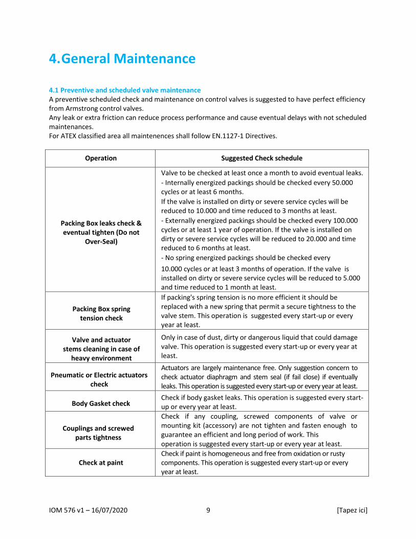
4. General Maintenance 4.1 Preventive and scheduled valve maintenance A preventive scheduled check and maintenance on control valves is suggested to have perfect efficiency from Armstrong control valves. Any leak or extra friction can reduce process performance and cause eventual delays with not scheduled maintenances. For ATEX classified area all maintenences shall follow EN.1127‐1 Directives.
Operation Suggested Check schedule
Packing Box leaks check & eventual tighten (Do not
Over-Seal)
Valve to be checked at least once a month to avoid eventual leaks.
- Internally energized packings should be checked every 50.000 cycles or at least 6 months.
If the valve is installed on dirty or severe service cycles will be reduced to 10.000 and time reduced to 3 months at least.
- Externally energized packings should be checked every 100.000 cycles or at least 1 year of operation. If the valve is installed on dirty or severe service cycles will be reduced to 20.000 and time reduced to 6 months at least.
- No spring energized packings should be checked every
10.000 cycles or at least 3 months of operation. If the valve is installed on dirty or severe service cycles will be reduced to 5.000 and time reduced to 1 month at least.
Packing Box spring tension check
If packing's spring tension is no more efficient it should be replaced with a new spring that permit a secure tightness to the valve stem. This operation is suggested every start-up or every year at least.
Valve and actuator stems cleaning in case of
heavy environment
Only in case of dust, dirty or dangerous liquid that could damage valve. This operation is suggested every start-up or every year at least.
Pneumatic or Electric actuators check
Actuators are largely maintenance free. Only suggestion concern to check actuator diaphragm and stem seal (if fail close) if eventually leaks. This operation is suggested every start-up or every year at least.
Body Gasket check Check if body gasket leaks. This operation is suggested every start-up or every year at least.
Couplings and screwed parts tightness
Check if any coupling, screwed components of valve or mounting kit (accessory) are not tighten and fasten enough to guarantee an efficient and long period of work. This operation is suggested every start-up or every year at least.
Check at paint Check if paint is homogeneous and free from oxidation or rusty components. This operation is suggested every start-up or every year at least.

IOM 576 v1 – 16/07/2020 10 [Tapez ici]
4.2 Notes and instructions
Due to the risk of injury, it is prohibited to work between the yoke/columns area while the valve is in operation.
4.2.1 General notes for maintenance Before to start with any maintenance on the control valves please double check the following points:
- Valve are pressure vessels. Actuator shall not be under pressure during maintenance. - Upstream pipeline is correctly by-passed or out of service. - Valve temperature is ambient. - Valve is not contaminated by dangerous substances contained in the process medium or on the
valve surface. If any of the above mentioned points will not be checked or taken in consideration the risk of injuries or death is existing. lf the customer performs the repairs himself, these operating instructions and the respective disassembly/assembly instructions must be followed to the letter and carried out in a competent manner. Original replacement parts must be used in every case. 4.2.2 Maintenance instructions Maintenance instructions described below shall be printed and followed step by step from assigned personnel on plant site during every operation on the control valve. This operating manual scope is to list all the necessary operations to:
- substitute a Valve part (disassembling the Valve body) - calibrate/adjust actuator's spring load - regulate valve stroke - adjust packing friction - reverse the valve action

IOM 576 v1 – 16/07/2020 11 [Tapez ici]
!
4.3 Intro Components Maintenance Customer to be sure to provide proper overhead clearance for the actuator to allow for disassembly of the valve components for body. Refer to Table 1 for the clearance needed for valve disassembly.
Table 1: Overhead Clearance Requirement
Valve Size [mm] Minimum Top Clearance [mm]
From DN.15 to 100 and with Actuator up to 430 200
From DN.15 to 100 and with Actuator 430s or bigger 250
From DN.125 to 200 and with Actuator 430s or bigger 300
From DN.250 to 300 and with Actuator 500s or Piston type 400
Depressurize the line to atmospheric pressure and drain all fluids before working on the valve. Control valves are pressure vessels! Improper opening of the actuator or fitting may result in bodily injury !
Make a complete inspection of the plug, seat rings and stem to determine whether these parts should be reused, reworked or replaced. NOTE: For an easy inspection of the valve trim, the bonnet may be removed from the valve body with the actuator still mounted and attached to the valve stem. To minimize the possibility of leakage, always replace the body-bonnet gasket and packing whenever the valve is disassembled.

IOM 576 v1 – 16/07/2020 12 [Tapez ici]
4.3.1 Actuator Diaphragm Replacement To Replace the actuator Diaphragm please read with attention the instructions and the pictures below. It is not necessary to disassemble the valve from the line nor the actuator from valve assembly. 1. Unscrew all actuator's bolting (pos.1) keeping the longer screws as last to discharge springs
gradually. 2. Remove the upper actuator housing (pos.2) with care. 3. Unlock actuator's stem Locknut (pos.3) 4. Remove springs (in case reverse acting), clamp plate and the old Diaphragm. 5. Replace with new Diaphragm and repeate the above points in the opposite way with the suggestion
to apply a threadlock glue to fix the locknut securely.
Diaphragm Actuator Maximum Supply Pressure
Actuator Type Nominal Pressure Suggested Maximum Pressure Barg / PSIg
S.200 PN 6 4,5 / 66
S.275 - S.335 PN 6 3,5 / 52
S.430 - S.430s PN 6 3,5 / 52
S.500 - S.500s PN 6 3,5 / 52
S.430 Tandem - S.500 Tandem PN 6 3,5 / 52

IOM 576 v1 – 16/07/2020 13 [Tapez ici]
4.3.2 Actuator Removal / Mounting Actuator Removal (Picture Page 15) 1. Disconnect actuator and valve stem by removing stem clamp bolts (pos.1) or joint for pillar yoke.
WARNING: On fail-closed actuators, the preadjusted spring force is effective. Therefore, apply enough air pressure to the actuator to stroke the stem to the mid- position (50 percent stroke) before disconnecting actuator and valve stem.
2. Reduce the loading pressure in the actuator to atmosphere. 3. Disconnect the pneumatic connection to the actuator. 4. Remove the yoke nut (pos.2) from the bonnet. 5. If the actuator does not lift freely off the bonnet, then apply pressure to the actuator and drive the
plug into the seat. This should drive lift the yoke off the bonnet. 6. Lift the actuator off the valve. Actuator Mounting (Picture Page 16) 1. Push the plug stem down into the seat by hand to fully close the valve. 2. Replace the complete actuator. Clean the threads on the bonnet, using a light oil or fluid. Replace the
complete actuator onto the bonnet and install yoke nut loosely. 3. Connect an adjustable air supply to the actuator. 4. On direct-acting actuators (air-to-close / fail-open): Apply sufficient air pressure to the actuator to
extend the actuator stem (pos.3) to 100 percent of stroke. Using a scale, measure and verify the stroke of the actuator stem. Stop stem travel once full stroke has
been reached. With the stem in this position, adjust the two stem clamp halves and connect them using the stem clamp bolting.
5. On reverse-acting actuators (air-to-open / fail- closed): Retract the actuator stem (…..) until it stops against the upper diaphragm case (…..). From this position, using an adjustable air supply and a scale, measure and verify the valve stroke. Once the stem has traveled full stroke, stop the travel and hold the stem in this position. Adjust the two stem clamp halves and install the stem clamp bolting.
6. While attaching the stem clamp (pos.1) (pillar yoke), make sure there is full engagement of the threads on the stems. Make sure to install the stroke indicator pointer and fully tighten the stem clamp cap bolts and nuts (pos.1).
7. With the yoke nut loose, stroke the valve two or three times to line up the yoke. Next, position the valve at mid stroke (50 percent open).
8. Completely tighten the yoke nut securing the actuator firmly to the valve. 9. Slight adjustments can be made (with the plug off the seat) by re-adjusting the stem clamp positions
or screw/ unscrew the same. 10. Re-adjust the stroke plate as necessary.

IOM 576 v1 – 16/07/2020 14 [Tapez ici]
Reversing Actuator Action 1. Remove actuator from valve body (see Actuator Removal Procedures steps 1-6). 2. Remove the short diaphragm case bolts and nuts (pos.5) around the diaphragm chamber keeping
longer bolts. 3. Remove thread covers from the long spring compression bolts. Lubricate the threads of the spring
compression bolts with a light oil or grease. Gradually loosen each of the long spring compression nuts, alternatively by one or two turns to progressively relieve the compression of the actuator springs inside the chamber.
WARNING: Long spring compression bolts must always be removed last to ensure the spring compression is fully released before the diaphragm upper housing is removed.
4. Remove the upper diaphragm housing (pos.4). 5. Remove actuator stem locknut (pos.6) on the top of actuator stem (pos.3). Diaphragm washer,
diaphragm , spring plate, stem bushing ring and springs (assembly 7) may now be removed. 6. Assemble the internal parts in accordance with Figure A air-to-close / fail-open (direct-acting) or
Figure B air-to-open / fail-closed (reverse-acting). Follow above disassembly procedure 1 to 4 in reverse sequence. To simplify assembly, position the actuator in a vertical position.
IOM 576 v1 – 16/07/2020 15 [Tapez ici]
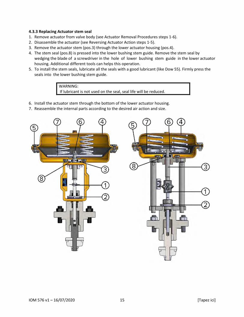
4.3.3 Replacing Actuator stem seal 1. Remove actuator from valve body (see Actuator Removal Procedures steps 1-6). 2. Disassemble the actuator (see Reversing Actuator Action steps 1-5). 3. Remove the actuator stem (pos.3) through the lower actuator housing (pos.4). 4. The stem seal (pos.8) is pressed into the lower bushing stem guide. Remove the stem seal by
wedging the blade of a screwdriver in the hole of lower bushing stem guide in the lower actuator housing. Additional different tools can helps this operation.
5. To install the stem seals, lubricate all the seals with a good lubricant (like Dow 55). Firmly press the seals into the lower bushing stem guide.
WARNING: If lubricant is not used on the seal, seal life will be reduced.
6. Install the actuator stem through the bottom of the lower actuator housing. 7. Reassemble the internal parts according to the desired air action and size.

IOM 576 v1 – 16/07/2020 16 [Tapez ici]
4.3.4 Replacing Plug & Seat Replacing Plug 1. On fail-closed actuators, the preadjusted spring force is effective. Therefore, apply enough air
pressure to the actuator to stroke the stem to mid- stroke before disconnecting actuator and valve stem.
2. Remove the bonnet nuts (pos.1). 3. Lift off the bonnet, actuator and plug as an assembly. 4. Disconnect actuator stem (pos.2) and plug stem (pos.3) by removing the stem joint or unscrew the
plug stem's nuts depending on the yoke type as shown in the below Figures. 5. Loosen the packing box gland (pos.4) until finger-tight. 6. Remove the plug (pos.5) from the bonnet (pos.6). A replacement plug may now be fitted if
required. When withdrawing or replacing the valve stem use a gentle turning motion to avoid damage to the packing material.
NOTE: The plug and packing should be replaced at the same time. (See Packing Replacement.). Special plugs designed for specific services needs separate apposite instructions for maintenance.
7. Replace the body gasket (pos.7) after cleaning its location surface from dirty. 8. Re-assemble all the items in reverse order checking at the perfect plug-actuator stems alignment.
IOM 576 v1 – 16/07/2020 17 [Tapez ici]
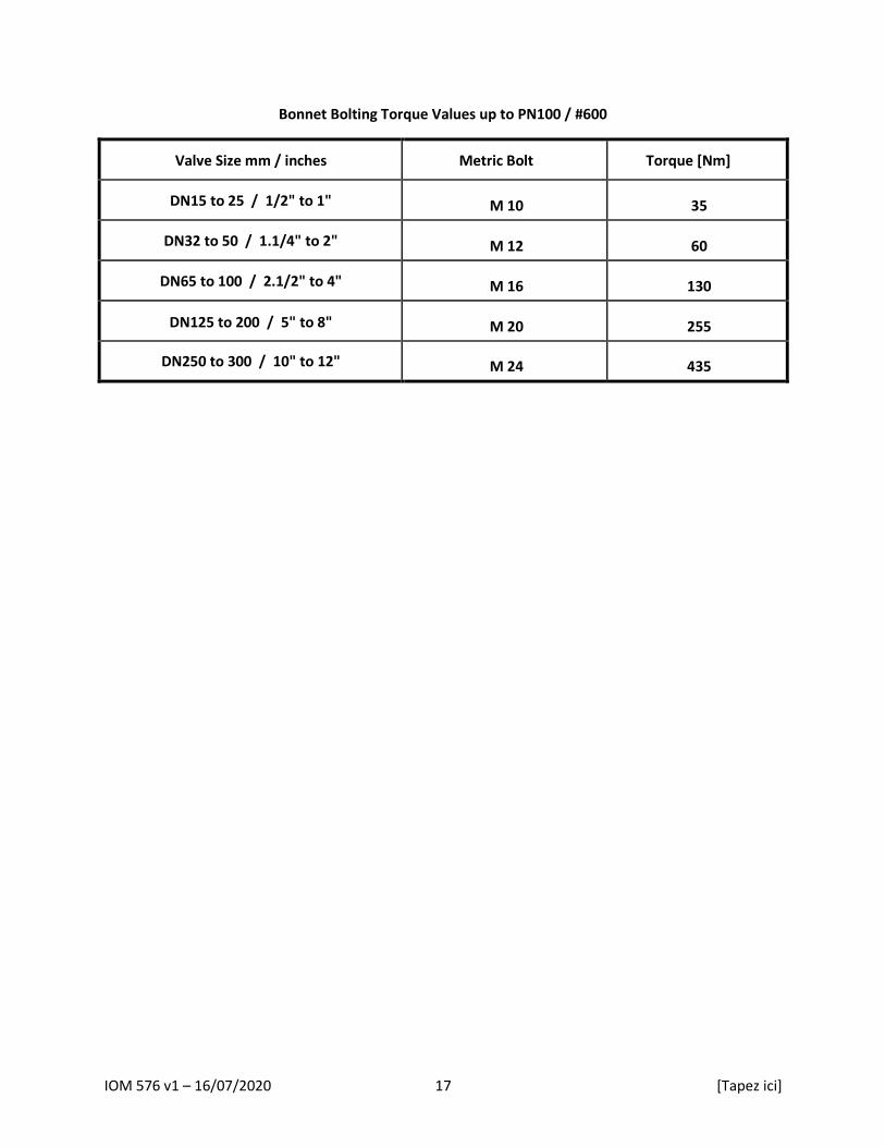
Bonnet Bolting Torque Values up to PN100 / #600
Valve Size mm / inches Metric Bolt Torque [Nm]
DN15 to 25 / 1/2" to 1" M 10 35
DN32 to 50 / 1.1/4" to 2" M 12 60
DN65 to 100 / 2.1/2" to 4" M 16 130
DN125 to 200 / 5" to 8" M 20 255
DN250 to 300 / 10" to 12" M 24 435

IOM 576 v1 – 16/07/2020 18 [Tapez ici]
Replacing Seat 1. Remove the actuator, bonnet and plug from the valve body (See Replacing Plug Procedure points 1-
5). 2. Replace the seat ring using a suitable seat-ring tool.
Seat-ring tool can be purchased from Delta 2 if required. 3. Apply high-performance lubricant to the threads on the seat ring. When refitting the seat ring,
additives are also advantageous if compatible with the process fluid.
Seat Ring Torque Values
Valve Size mm / inches Torque [Nm]
DN15 to 25 / 1/2" to 1" 70
DN32 to 50 / 1.1/4" to 2" 225
DN65 to 100 / 2.1/2" to 4" 980
DN125 to 200 / 5" to 8" 2150
DN250 to 300 / 10" to 12" 3450
IOM 576 v1 – 16/07/2020 19 [Tapez ici]
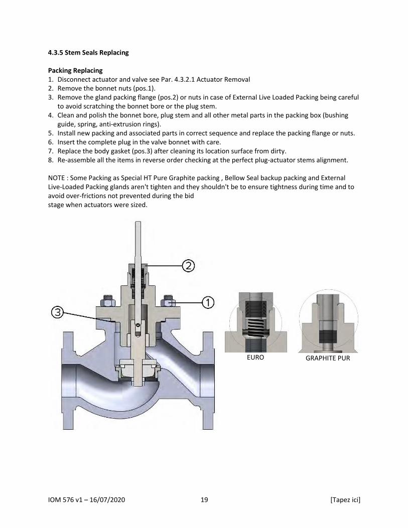
4.3.5 Stem Seals Replacing Packing Replacing 1. Disconnect actuator and valve see Par. 4.3.2.1 Actuator Removal 2. Remove the bonnet nuts (pos.1). 3. Remove the gland packing flange (pos.2) or nuts in case of External Live Loaded Packing being careful
to avoid scratching the bonnet bore or the plug stem. 4. Clean and polish the bonnet bore, plug stem and all other metal parts in the packing box (bushing
guide, spring, anti-extrusion rings). 5. Install new packing and associated parts in correct sequence and replace the packing flange or nuts. 6. Insert the complete plug in the valve bonnet with care. 7. Replace the body gasket (pos.3) after cleaning its location surface from dirty. 8. Re-assemble all the items in reverse order checking at the perfect plug-actuator stems alignment. NOTE : Some Packing as Special HT Pure Graphite packing , Bellow Seal backup packing and External Live-Loaded Packing glands aren't tighten and they shouldn't be to ensure tightness during time and to avoid over-frictions not prevented during the bid stage when actuators were sized.
EURO
GRAPHITE PUR

IOM 576 v1 – 16/07/2020 20 [Tapez ici]
!
Bellow Backup Packing Replacing 1. Disconnect actuator and valve see Par. 4.3.2.1 Actuator Removal 2. Remove the bonnet nuts (pos.1). 3. Untight the threaded locking ring (pos.2) and depending on Bellow Seal type remove the gland
packing flange (pos.3) or nuts in case of External Live Loaded Packing being careful to avoid scratching the bonnet bore or plug stem.
4. Remove the bonnet (pos.4) from the valve body. 5. Extract the complete plug (pos.5) together with stem and the welded bellow assembly 6. Clean and polish the bonnet bore, plug stem and all other metal parts in the packing box (bushing
guide, spring, anti-extrusion rings). 7. Re-assemble all the items in reverse order checking at the perfect plug-actuator stems alignment.
WARNING : If Bellow seal upper thread is tighten to the bonnet flange any little plug rotation MUST be avoided to not permit the bellow to twist around upon itself damaging or breaking its walls (2 or 3 layers)
IOM 576 v1 – 16/07/2020 21 [Tapez ici]
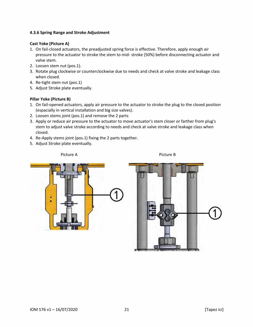
4.3.6 Spring Range and Stroke Adjustment Cast Yoke (Picture A) 1. On fail-closed actuators, the preadjusted spring force is effective. Therefore, apply enough air
pressure to the actuator to stroke the stem to mid- stroke (50%) before disconnecting actuator and valve stem.
2. Loosen stem nut (pos.1). 3. Rotate plug clockwise or counterclockwise due to needs and check at valve stroke and leakage class
when closed. 4. Re-tight stem nut (pos.1) 5. Adjust Stroke plate eventually. Pillar Yoke (Picture B) 1. On fail-opened actuators, apply air pressure to the actuator to stroke the plug to the closed position
(espacially in vertical installation and big size valves). 2. Loosen stems joint (pos.1) and remove the 2 parts 3. Apply or reduce air pressure to the actuator to move actuator's stem closer or farther from plug's
stem to adjust valve stroke according to needs and check at valve stroke and leakage class when closed.
4. Re-Apply stems joint (pos.1) fixing the 2 parts together. 5. Adjust Stroke plate eventually. Picture A
Picture B

IOM 576 v1 – 16/07/2020 22 [Tapez ici]
5. Repair Problem 1 - Stem motion impeded Probable Cause: 1. Overtightened packing 2. Service temperature is beyond operating limits of trim design 3. Inadequate air supply pressure Corrective Action : 1. Adjust packing box gland flange or Live Loaded nuts to slightly over finger-tight 2. Reconfirm service conditions and contact factory 3. Check for leaks in air supply or instrument signal system; tighten loose connections and replace leaky
lines, verify spring set values Problem 2 - Excessive leakage Probable Cause: 1. Malfunctioning positioner 2. Improperly tightened bonnet flange bolting 3. Worn or damaged seat ring 4. Inadequate actuator thrust 5. Incorrectly adjusted plug 6. Incorrectly adjusted "zero" adjustment locknut/joint 7. Improper handwheel adjustment acting as a limit stop Corrective Action : 1. Refer to positioner maintenance instruction manual 2. Refer to Preventive Maintenance section for correct tightening procedure 3. Disassemble valve and replace or repair seat ring, follow procedure in Replacing Plug and Seat 4. Check for adequate air supply to actuator; verify spring set values; if air supply is adequate, reconfirm
service conditions and contact factory 5. Refer to Stroke Length Adjustment for correct plug adjustment 6. Recalibrate positioner 7. Adjust handwheel until plug seats properly

IOM 576 v1 – 16/07/2020 23 [Tapez ici]
Problem 3 - Inadequate flow Probable Cause: 1. Improper plug adjustment, limiting stroke 2. Malfunctioning positioner 3. Service conditions exceed trim design capacity 4. Insufficient air supply pressure Corrective Action : 1. Refer to Stroke Length Adjustment for correct plug adjustment 2. Refer to positioner maintenance instruction manual 3. Verify service conditions and consult factory 4. Check for adequate air supply to actuator; verify spring set values; if air supply is adequate, reconfirm
service conditions and contact factory Problem 4 - Plug slams on the seat Probable Cause: 1. Valve installed with incorrect flow direction Corrective Action : 1. Install valve following the arrow of flow direction on valve body Problem 5 - Valve does not fail in correct position Probable Cause: 1. Valve installed with incorrect flow direction 2. Actuator with wrong failure direction Corrective Action : 1. Install valve following the arrow of flow direction on valve body 2. Reverse spring failure direction on actuator; refer to Reversing the Actuator Action
IOM 576 v1 – 16/07/2020 24 [Tapez ici]
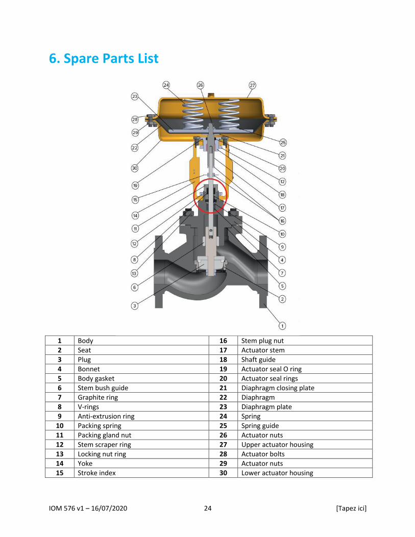
6. Spare Parts List
1 Body 16 Stem plug nut
2 Seat 17 Actuator stem
3 Plug 18 Shaft guide
4 Bonnet 19 Actuator seal O ring
5 Body gasket 20 Actuator seal rings
6 Stem bush guide 21 Diaphragm closing plate
7 Graphite ring 22 Diaphragm
8 V-rings 23 Diaphragm plate
9 Anti-extrusion ring 24 Spring
10 Packing spring 25 Spring guide
11 Packing gland nut 26 Actuator nuts
12 Stem scraper ring 27 Upper actuator housing
13 Locking nut ring 28 Actuator bolts
14 Yoke 29 Actuator nuts
15 Stroke index 30 Lower actuator housing
IOM 576 v1 – 16/07/2020 25 [Tapez ici]
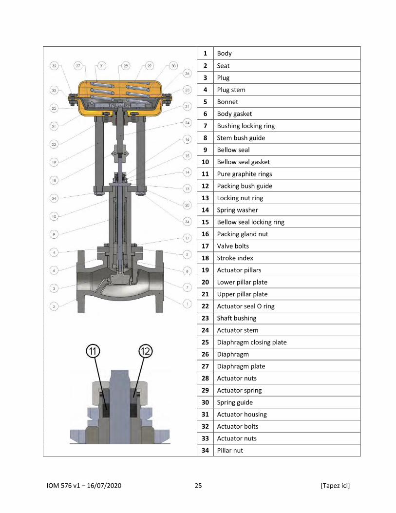
1 Body
2 Seat
3 Plug
4 Plug stem
5 Bonnet
6 Body gasket
7 Bushing locking ring
8 Stem bush guide
9 Bellow seal
10 Bellow seal gasket
11 Pure graphite rings
12 Packing bush guide
13 Locking nut ring
14 Spring washer
15 Bellow seal locking ring
16 Packing gland nut
17 Valve bolts
18 Stroke index
19 Actuator pillars
20 Lower pillar plate
21 Upper pillar plate
22 Actuator seal O ring
23 Shaft bushing
24 Actuator stem
25 Diaphragm closing plate
26 Diaphragm
27 Diaphragm plate
28 Actuator nuts
29 Actuator spring
30 Spring guide
31 Actuator housing
32 Actuator bolts
33 Actuator nuts
34 Pillar nut

IOM 576 v1 – 16/07/2020 26 [Tapez ici]
7. Limited Warranty and Remedy Armstrong International S.A. (“Armstrong”) warrants to the original user of those products supplied by it and used in the service and in the manner for which they are intended, that such products shall be free from defects in material and workmanship for a period of one (1) year from the date of installation, but not longer than 15 months from the date of shipment from the factory [unless a Special Warranty Period applies, as listed below]. This warranty does not extend to any product that has been subject to misuse, neglect, or alteration after shipment from the Armstrong factory. Except as may be expressly provided in a written agreement between Armstrong and the user, which is signed by both parties, Armstrong DOES NOT MAKE ANY OTHER REPRESENTATIONS OR WARRANTIES, EXPRESS OR IMPLIED, INCLUDING, BUT NOT LIMITED TO, ANY IMPLIED WARRANTY OF MERCHANTABILITY OR ANY IMPLIED WARRANTY OF FITNESS FOR A PARTICULAR PURPOSE. The sole and exclusive remedy with respect to the above limited warranty or with respect to any other claim relating to the products or to defects or any condition or use of the products supplied by Armstrong, however caused, and whether such claim is based upon warranty, contract, negligence, strict liability, or any other basis or theory, is limited to Armstrong’s repair or replacement of the part or product, excluding any labor or any other cost to remove or install said part or product, or, at Armstrong’s option, to repayment of the purchase price. As a condition of enforcing any rights or remedies relating to Armstrong products, notice of any warranty or other claim relating to the products must be given in writing to Armstrong: (i) within 30 days of last day of the applicable warranty period, or (ii) within 30 days of the date of the manifestation of the condition or occurrence giving rise to the claim, whichever is earlier. IN NO EVENT SHALL ARMSTRONG BE LIABLE FOR SPECIAL, DIRECT, INDIRECT, INCIDENTAL OR CONSEQUENTIAL DAMAGES, INCLUDING, BUT NOT LIMITED TO, LOSS OF USE OR PROFITS OR INTERRUPTION OF BUSINESS. The Limited Warranty and Remedy terms herein apply notwithstanding any contrary terms in any purchase order or form submitted or issued by any user, purchaser, or third party and all such contrary terms shall be deemed rejected by Armstrong.
IOM-576 v1
Printed in Europe – 7/20
© 2020 Armstrong International SA.