flutter tests on some delta wings using ground-launched...
TRANSCRIPT
gOYAL ~;I~CRAF ~ ~:;TAKLISHMEN r
~DFORD. R. & M. No. 3231
K
MINISTRY OF AVIATION
A E R O N A U T I C A L RESEARCH C O U N C I L
REPORTS A N D M E M O R A N D A
Flutter Tests on some Delta Wings using Ground-Launched Rockets
W. G. MOLYNEUX, B.Sc. and F. RUDDLESDEN, A.M.I.E.I.
(~ Crow~ copyrigAt I96I
LONDON : HER MAJESTY'S STATIONERY OFFICE
I961
V~lCE 6S. 6,/. N~T

Flutter Tests on some Delta Wings using Ground-Launched Rockets
By
W. G. I~/IOLYNEUX, B.Sc. and F. RUDDLESDEN, A . M . I . E . I ,
COMMUNICATED BY THE PRINCIPAL DIRECTOR oF SCIENTIFIC RESEARCH (AIR),
MINISTRY OF SUPPLY
Reports a z d Memorazda No. 3 2 3 1 *
February, 19 5 5
Summary.--This report gives the results of tests on flutter models of cropped delta wings having 40, 50 and 60 deg leading-edge sweepback and a taper ratio of 1 : 7.
A comparison is made between the measured flutter speeds and the speeds estimated using a flutter speed formula, and the estimated speeds are found to be within 4-15 per cent of the measured speeds. A modification to the formula is proposed to allow for the high values of stiffness ratio that are obtained for delta wings.
1. Introduction.--Some f lut ter tests at high Mach n u m b e r on unswept and swept wings have been described in earlier reports 1, 2, a n d the results of these tests have been used for the develop- men t of a formula tha t enables a reasonable es t imate of wing flutter speeds to be obta ined from known propert ies of the wings.
In the present report tests on cropped del ta wings having 40, 50 and 60 deg leading-edge sweepback and a taper ratio 1 : 7 are described. The flutter speed formula 2 is used to obtain est imates Of f lut ter speeds for the wings, and in general the es t imated speeds are in reasonable agreement wi th the measured speeds.
The ratio of flexural to torsional stiffness is in pract ice general ly greater for del ta wings than for unswept and swept wings, and is f requent ly outside the limits prescribed in the flutter speed formula. An a m e n d m e n t to the factor in the formula tha t involves stiffness ratio is therefore proposed to enable the formula to be applied over a wider range of stiffness ratio.
Wi th this modificat ion the es t imated speeds are within ~ 15 per cent of the measured speeds for all the del ta wings tested. These limits are similar to those obta ined on unswept and swept wings 1'2
2. Details of the Modds . - -A typical assembly of a del ta wing on a five-inch d iameter rocket is shown in Fig. 1. The peak speed t ha t could be achieved for this assembly was about 2,000 ft/sec, 1.8 Mach number . Wings having 40, 50 and 60 deg leading-edge sweepback and a taper ratio of 1 : 7 were tested. The external dimensions of the wings and details of the wing construct ion are given in Table 1. The thickness /chord ratio as measured in the line-of-flight direct ion was 0. 090 for the wings wi th 40 deg leading-edge sweepback, 0. 070 for 50 deg sweepback and 0" 045 for 60 deg sweepback. Inc luded in Table 1 are details of a del ta wing tes ted in a low speed
* Previously issued as R.A.E. Report Structures 173--A.R.C. 17,752.
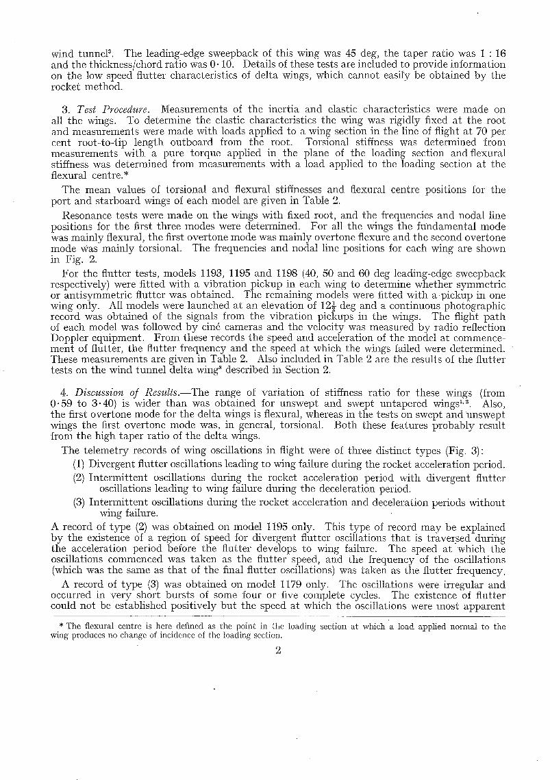
wind tunneP. The leading-edge sweepback of this wing was 45 deg, the taper ratio was 1 : 16 and the thickness/chord ratio was 0.10. Details of these tests are included to provide information on the low speed flutter characteristics of delta wings, which cannot easily be obtained by the rocket method.
3. Test Procedure.--Measurements of the inertia and elastic characteristics were made on all the wings. To determine the elastic characteristics the wing was rigidly fixed at the root and measurements were made with loads applied to a wing section in the line of flight at 70 per cent root-to-tip length outboard from the root. Torsional stiffness was determined from measurements with a pure torque applied in the plane of the loading section and flexural stiffness was determined from measurements with a load applied to the loading section at the flexural centre.*
Tile mean values of torsional and flexural stiffnesses and flexural centre positions for the port and starboard wings of each model are given in Table 2.
Resonance tests were made on the wings with fixed root, and the frequencies and nodal line positions for the first three modes were determined. For all the wings the fundamental mode was mainly flexural, the first overtone mode was mainly overtone flexure and the second overtone mode was mainly torsional. The frequencies and nodal line positions for each wing are shown in Fig. 2.
For the flutter tests, models 1193, 1195 and 1198 (40, 50 and 60 deg leading-edge sweepback respectively) were fitted with a vibration pickup in each wing to determine whether symmetric or antisymmetric flutter was obtained. The remaining models were fitted with ap ickup in one wing only. All models were launched at an elevation of 12} deg and a continuous photographic record was obtained of the signals from the vibration pickups in the wings. The flight pa th of each model was followed by cin4 cameras and the velocity was measured by radio reflection Doppler equipment. From these records tile speed and acceleration of the model at commence- ment of flutter, the flutter frequency and the speed at which the wings failed were determined. These measurements are given in Table 2. Also included in Table 2 are the results of the flutter tests on the wind tunnel delta wing 3 described in Section 2.
4. Discussion of Results.---The range of variation of stiffness ratio for these wings ( f r o m 0.59 to 3.40) is wider than was obtained for unswept and swept untapered wings 1,~. Also, the first overtone mode for the delta wings is flexural, whereas in the tests on swept and unswept wings the first overtone mode was, in general, torsional. Both these features probably result from the high taper ratio of the delta wings.
The telemetry records of wing oscillations in flight were of three distinct types (Fig. 3): (1) Divergent flutter oscillations leading to wing failure during the rocket acceleration period. (2) Intermit tent oscillations during the rocket acceleration period with divergent flutter
oscillations leading to wing failure during the deceleration period. (3) Intermit tent oscillations during the rocket acceleration and deceleration periods without
wing failure. A record of type (2) was obtained on model 1195 only. This type of record may be explained by the existence of a region of speed for divergent flutter oscillations that is traversed during the acceleration period before the flutter develops to wing failure. The speed at "which the oscillations commenced was taken as the flutter speed, and the frequency of the oscillations (which was the same as that of the final flutter oscillations) was taken as the flutter frequency.
A record of type (3) was obtained on model 1179 only. The oscillations were irregular and occurred in very short bursts of some four or five complete cycles. The existence of flutter could not be established positively but the speed at which the oscillations were most apparent
* The flexural centre is here defined as the point in the loading section at which 'a load applied normal to the wing produces no change of incidence of the loading section.
2

was taken as the ' flutter ' speed and the frequency of the oscillations as the ' flutter ' frequency. The record may be explained by a near flutter condition in which the damping is small, so that the wing oscillates !or a few cycles when disturbed.
The three models (1193, 1195, 1198) that were fitted with two pickups to establish whether symmetric or antisymmetric flutter was obtained, all gave records of symmetric flutter.
No oscillations were recorded on models 1194 and 1197 up to the peak speeds of the rockets.
5. Comparison of Estimated and Measured Speeds.--An estimate of wing flutter speeds was obtained using the following flutter speed formulaL
1 7 1 = , ~ ] [ m° ~t"(0"9--0"33k)(l--O'Ir)(O'95+l'31#")O~Tg(g--O.l) sec ' I ' ( A - ~ 6 ) .. (I)
V ~ = Vl (1 - - 0"166Ml cos A) ; M l c o s A ~< 1"265
= 0 " 7 9 V ~ ; M~cosA > 1" 265
where V~ is the required estimated speed. (The symbols are defined in Table 2.) The estimated speeds and the ratio of measured speed to estimated speed are given in Table 2. The ratio of measured speed to estimated speed is plotted against M1 cos A in Fig. 4a.
I t should be noted that definite flutter points are Obtained only for values of M1 cos A < 1. Flutter of model 1179 (M, cos A = 1.76) was not positively established, and the points shown for models 1194 and 1197 are based upon peak rocket speed in the absence of any indications of flutter.
The results for the remainder of the models, which definitely fluttered, give estimated flutter speeds within + 15 per cent of the measured values, over a range of M1 cos A up to 0.74. This order of agreement is similar to that obtained for unswept and swept, untapered wings 2 and indicates tha t the formula can reasonably be applied to cropped delta wings despite the highly tapered plan-form. However, further tests would be required to ascertain whether the formula could be applied to tile pointed tip delta wing. I t seems probable tha t the formula would give a reasonable reslilt in this case, since the estimated speeds for the wind tunnel delta, taper ratio 1 • 16, give the same order of agreement with the measured speeds as was obtained for the flight models with taper ratio 1 • 7.
6. Modification to ~he Stiffness Ratio Factor.--A feature of delta wings is the high values of the stiffness ratio, r, that are obtained (Table 2). These are frequently outside the limits of variation 0" 5 < r < 2.0 specified for the formula ~, and in fact a stiffness ratio of 8 has been estimated in a recent design study for a delta wing. With the present form of the stiffness ratio factor the formula gives an unduly low estimate for the flutter speeds of high stiffness ratio wings. For instance, the estimated speed for model 1194 (r = 3.4) was 1,660 ft/sec whereas no flutter was recorded up to 2,000 ft/sec. Recent theoretical investigations for swept and unswept wings have shown that provided the fundamental flexural and torsional modes are well separated in frequency the effect of high stiffness ratio on flutter speed is small. This proviso is, in general, satisfied for delta wings.
In order, therefore, that tile formula may be applied for a wide range of stiffness ratio it is proposed to modify tile stiffness ratio factor from (1 -- 0. lr), 0.5 < r < 2.0 to (0.77 + 0.1/r), 0.5 < r. In the range of stiffness ratio from 0.5 to 2.0 the effect of this modification is small. At the same time the terms in the basic formulr~ that involve taper ratio and inertia axis position are simplified by the substitutions
(0.9 -- 0.33k) -- 0.61 C,~ C0.v
where c07 is the wing chord at 0.7s
0 . 7 8 ( g - - 0 " 1 ) ~ 0 . 6 1 g ;
; 0 ~ k ~ l
0 . 3 5 ~ g ~ 0 . 6 .
3

With these substitutions the expression for V1 is then given by
VI [_too ~1~(0"77 + 0 . l / r ) (0 .95 + 1.3/a~) ( ~ ) = \poSC,, ! g sec A - - i 9 . . . . (2)
The effect of this revised formula for these wings is shown in Table 2 and Fig. 4b. The agreement between measured and estimated speeds for wings of high stiffness ratio is, in general, improved, and in particular the estimated speed for model 1194 is raised from 1,660 ft/sec to 1,984 ft/sec which is within 1 per cent of the peak speed of the rocket. The above modifications have also been applied to flutter speed estimates for the unswept and swept wings 2 and in general the effect is small. However, the agreement between measured and estimated speeds for wings of high stiffness ratio is somewhat improved, and for one wing the error in the estimated speed is reduced from --27 per cent to --13 per cent of the measured speed.
7. Definition of the Sweepback Line.--In the results of Figs. 4a and 4b the estimated flutter speeds are obtained by taking the sweepback angle A in the formula as the sweepback of the leading edge. It has been customary, both for tapered sweptback wings and delta wings, to consider the effective sweepback angle as lying between the leading and trailing-edge sweepback angles. It is clear, however, that for the delta wings tested the use of the leading-edge sweepback m the flutter speed formula gives the best results. In Fig. 5 the results of Fig. 4b are replotted using for A the sweepback of the 36 per cent chord line (i.e., 5 per cent of the chord behind the line of maximum thickness), as recommended in the official design requirements (AP.970, Part 5). The mean ratio of measured to estimated speeds is about 25 per cent greater than that obtained using the leading-edge sweepback, and represents a considerable margin of stiffness from the design viewpoint. However, this margin should not be regarded too seriously since it is obtained from results on a small number of wings.
It is perhaps worth noting that the original derivation 5 of the sweepback factor in the flutter speed formula was on the basis of rotation of unswept wings (aspect ratio = 8) to a swept position, resulting not only in a variation of leading-edge sweep but also a variation in wing aspect ratio.
As a result of more recent work 6 it has been possible to separate the aspect ratio and sweep effects for swept wings. For the original wings 5 the substitution can be made :
sec - /16) o . 9 (1 + 0 - 8 / A ) sec (A - -
where A is the exposed wing aspect ratio (A = 2s/c,,),
leading to the current expression for V1 for swept wings 7.
( mo ~1'~0"9 (0.77 -b 0.l /r) (1 -F 0.8/A) ( ~ ) v l = p0 T0 g sec . A - - 1 9 . . . . . (S)
(The term (0.95 + 1-3/~) is omitted from (3) since for current designs of swept wing aircraft it has a negligible effect.)
Expression (3) has been applied to the present series of delta wings, and the results are shown in Table 3.
It can be seen that this formula leads to an overestimate of flutter speed for delta wings, the agreement between measured and predicted speeds becoming progressively worse with increasing wing sweepback (decreasing aspect ratio). Apparently, for delta wings of high taper ratio where sweepback and aspect ratio are closely related, Expression (2) for V~ is to be preferred.
8. Conclusions.--Fhitter tests have been made on uniformly tapered cropped delta wings, and estimates of wing flutter speeds have been obtained using a flutter speed formula. The estimated speeds, are, in general, in reasonable agreement with those measured. However,

it is proposed to introduce a modified stiffness ratio factor into the formula so as to avoid unduly low speed estimates for wings of high stiffness ratio, such as delta wings. The modified formula is as follows"
(_ rn0 ~ ' 2 ( 0 . 7 7 + 0 . 1 / r ) ( 0 " 9 5 + 1.3/a~) ( ~ ) = see 3/~ A -- VI tOoSCo ~U g
V~ = Vt (1 -- 0"166 M~ cos A) ; M~ cos A ~< 1"265
= 0"79V1; M t c o s A > 1"265
where V2 is the required flutter speed estimate, M1 is the Mach number corresponding to the speed V1 and A is the sweepback of the wing leading edge.
The formula gives flutter speed estimates for these wings that are within ~: 15 per cent of the measured speeds2
Acknowledgement.--Acknowledgements are due to the Staff of Guided Weapons Dept., Trials Division for their assistance in the calibration and testing of these models.

-- N O T A T I O N Basic formula
_ ( mo V Io.9-0.33k/0-0. r//0.95+ 1"3/ o/ ( V~ -- \ ~ ] 0 - 7 8 ( g - - 0 . 1 ) see ~l~ A - - ] ~
Modified formula V~ = \ ~ ] [ mo ~i,2 (0" 77 + 0" I/r) g(0"95 + I. 3/a~) sec 3'2 .(A -- ]-6~ .)
M~ _ V~ (ao = local speed of sound-ft/sec a0
Y 2 ~--
V
M
V~
C~
Co.7
g
h
k
r
S
//6
m0
A
P0
Pw
(7 w
V1 (1 -- 0" 166 M1 cos A) ; M1 cos A ~< 1.265
0.79 V1 ; M1 cos A > 1"265
Measured critical flutter speed--ft/sec
Mach number at critical speed
Speed at wing failure--ft/sec
Wing mean chord--f t
Wing chord at 0 .7s- - f t
Distance of wing inertia axis aft of L.E. -- wing chord ;
Distance of wing flexural centre aft of L.E. -- wing chord
Wing taper ratio
tip chord O~k~l
root chord ;
Flutter frequency--c.p.s.
Stiffness ratio
l~ c,,, ~ 0" 5 ~< r 0-81 m o s ~ ;
Wing length root to t ip - - f t
Rocket acceleration + gravitational acceleration
Wing flexural stiffness measured at 0 .7s-- lb ft/rad
Wing torsional stiffness measured at 0" 7s--1b ft/rad
Leading-edge sweepback
Air density at sea level--slugs/cu It
Wing density--slugs/cu ft
mass of one wing S¢,,~ 2
Flutter frequency parameter
V Wing relative density
P,o/Po
6
0.35 ~<g ~ 0 . 6

NO.
1
R E F E R E N C E S
Author Title, etc.
W. G. Molyneux, F. Ruddlesden and P. J. Cutt . . Technique for flutter tests using ground-launched rockets, with unswept wings. A.R.C. R. & M. 2944. November, 1951.
2 W . O . Molyneux and F. Ruddlesden Some flutter tests on sweptback wings using ground launched rockets. A.R.C. R. & M. 2949. October, 1953.
3 D . R . Oaukroger, E. W. Chapple and A. Milln .. Wind tunnel flutter tests on a model delta wing under fixed and free root conditions. A.R.C. R. & M. 2826. September, 1950.
4 A . R . Collar, E. G. Broadbent and E. B. Puttick An elaboration of the criterion for wing torsional stiffness. A.R.C. R. & M. 2154. January, 1946.
5 W . G . Molyneux The flutter of swept and unswept wings with fixed-root conditions. A.R.C. R. & M. 2796. January, 1950.
6 W . O . Molyneux and H. Hall The aerodynamic effects of aspect ratio and sweepback on wing flutter. A.R.C. R. & M. 3011. February, 1955.
7 W . G . Molyneux Approximate formulae for flutter prediction. Aircraft E~¢gineering, Vol. xxxii. No. 382. December, 1960.
7
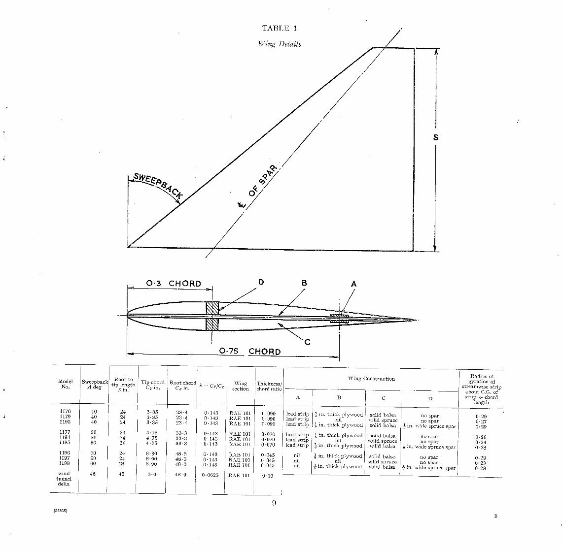
TABLE 1
Wing Details
/
J /
/ Ip
$
0 . 3 CHORD D B A
CHORD C ~ 0 .75
Model No,
1176 1179 1193
1177 1194 1195
1196 1197 1198
wind tunnel delta
Sweepback A deg
40 40 40
50 50 50
60 60 60
45
Root to t ip length
S in.
24 24 24
24 24 24
24 24 24
45
Tip chord CT in.
3 '35 3 ' 3 5 3 '35
4.75 4.75 4.75
6.90 6.90 6.90
3 .0
Root chord C~ in.
23.4 23.4 23.4
33.3 33.3 33.3
48.3 48.3 48.3
48 .0
O. 143 O. 143 O. 143
0.143 0.143 0.143
0.143 0.143 0.143
0.0625
Wing section
RAE 101 RAE 101 RAE 101
RAE 101 RAE 101 RAE 101
RAE 101 RAE 101 RAE 101
.RAE 101
Thickness/ chord ratio
O. 090 0.090 O. 090
0.070 0.070 0.070
O. 045 0.045 0.045
0-10
A
lead str ip lead str ip lead str ip
1cad str ip lead str ip lead str ip
nil nil nil
W i n g Cons t ruc t ion
B
in. th ick p lywood nil
1 in. th ick p lywood
½ in. th ick p lywood nil
in. th ick p lywood
-~ in. th ick p lywood nil
-~ in. th ick p lywood
solid balsa solid spruce solid balsa
solid ba lsa solid spruce solid balsa
solid balsa solid spruce solid ba lsa
D
no spar no spar
½ in. wide spruce spar
no spar no spar
{- in. wide spruce spar
no spar no spar
½ in. wide spruce spar
Radius of gyrat ion of
streamwise strip about C.G. of str ip + chord
length
0-29 0-27 0-29
0.26 0-24 0.28
0.29 O. 23 0.28
9 (828o5)
B

TABLE 2
Comparison of Estimated Speeds with Measured Speeds
Model
No.
1176
1179
1193
1177
1194
1195
1196
1197
1198
\Vind
Tunne l
Del ta
40 2-0
40 2 .0
40 2 .0
50 2 .0
50 2 .0
50 2-0
60 2 .0
60 2- 0
60 2-0
k 3" 45
Data from Laboratory Tests
Cm ft
1.12 0. 143
1- 12 0. 143
1- 12 0. 143
1.58 0. 143
1.58 0 .143
1.58 0 .143
2 .30 0.143
2 .30 0 ,143
2 .30 0. 143 i
75 2 .12 0 ~ 0 ~ 2 5
t6 mo k l b f t ] lb ft] h
radn radn
~w lb/cu
It
E s t i m a t e d Speeds
f t /sec s e n f t /sec
Measured F lu t t e r Values Ra t i o
V n V~, V /V . f t /sec M c.p.s, w,~ f[g ft]see V1
Modified F o r m u l a
m 1 s e ~ V.
745
4,000
485
4,450
0 .10
0 .42
0-21
0-03
0 .59 0 50
2 .07 0 4 5
1.72 0 5 0
1.17 0 .50
3-40 0.'44
2-65 0 .43
1-26 0 .43
2-99 0 .42
1-86 0 .43
2 .40 0 .50
0 .45
0 .40
1 "39 910 0 .62
1"76
0-57
0-63
826
2,030
753
984
840 0 ' 7 5
1,820 1.63
0"75
0 .90
68 0 .57
85 0 .33
62 0 .52
59 0 .59
23 910
43 - -
26 950
20 1,070
2,340 525
1,600 1,060
:2,400 5,090
2,570 750
817 1,060
5 ,200 8,310
2,570 2,260
375 62
0-33
0 .14
0 .01
0 .27
0-08
2-59 2,570
1.51 832
1.14 1,100
1-78 2,060 1-18
0 .94 9 4 5 1 0 - 5 4
0-60 1,24C 0 .56
1-04 2,68G 1-20
0 .75 1,63C 0 .73
0 .92 117 0-074
134 0-085
156 0-099
1,660
859
1,125
2,150
1,435
115
127
153
840
1,000
No f lu t ter up to 2,000 f t / sec
910 0.81 60 0 .65 49
1,030 0 .92 50 0 .70 49
No f lut ter up to 1,900 ft]sec
1,270 1.14 45 0 .51 39
131-5 0-12 8 .1 0 .82
143.5 0- 13 7 .5 0 .70
146-0 0 .13 7-3 0 .67
1" 02
0-90
1"12
1-02 i
980 1.-06
1,200 0-92__
1,840 0 .89
948
2,692
869
1,112
2,511
1,042
1,207
3,053
1,653
0-650
1-846
0-596
0 .640
1 .445
0.600
0 .540
1-367
0 .740
845
2,126
783
994
1,984
938
1,099
2,412 1
1,450
1-14
1-13
0 .95
133-8
145.1
167.5
0-085
0 .092
0 .1 0 6
131-9
142.8
164.6
V / V .
0 .9 9
0 .8 6
1 .07
0-99
0 .97
0 .94
0 .8 8
1 .00
1 .00
0 .8 9
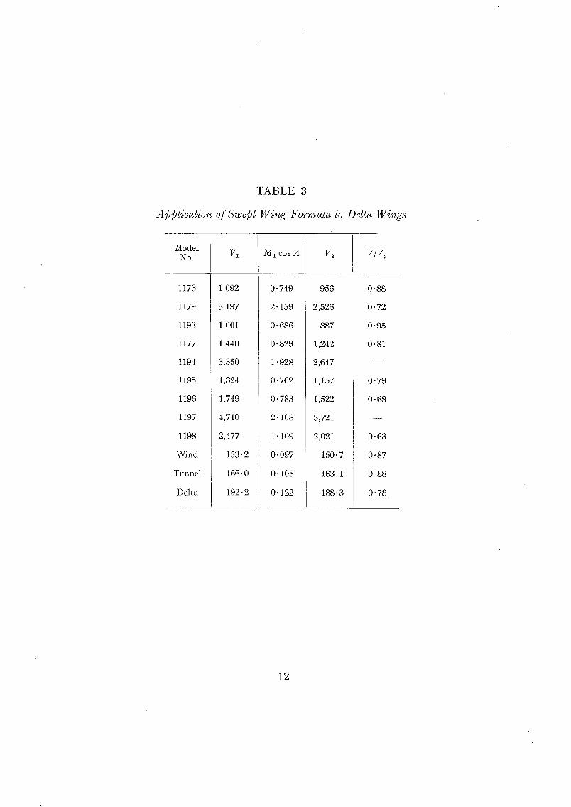
T A B L E 3
Application of Swept Wing Formula to Delta Wings
Model No.
1176
1179
1193
1177
1194
1195
1196
1197
1198
Wind
Tunnel
Delta
VI
1,092
3,197
1,001
1,440
3,350
1,324
1,749
4,710
2,477
153
166
192
M 1 cos A
o. 749
2. 159
o. 686
o. 829
1.928
o. 762
o. 783
2- lO8
1- lO9
.2 o. 097
• o o . lO5
• 2 o. 122
V~
956
2,526
887
1,242
2,647
1,157
1,522
3,721
2,o21
15o.7
163.1
188-3
V/V~
0"88
0.72
0 '95
0"81
O- 79
O- 68
0"63
O. 87
0.88
0.78
12

TELEMETRY SET \ - - - ~
CONDUIT.
PICK- UP.
PICK-UP LEADS
o oooo o o } O 0
= 0 o I
FIG. 1. Typical assembly--5 in. rocket.

2 E° OVERTONi::: = 116 C'PS " ~ 1 t . ~ . _ ~ / ' ~ ] / /
MODEL 1176
FUNDAMENTAL = 41 QP..S. F |S_T OVERTONE = 18-IC.P..~.// / . 2"--° OVERTONE = Z BZCP.5/'~/~ " / ~ ' -
MODEl_ 11-/9
FUNDAMENTAL = "~4 c.RS F IE OVE.RTONE = 3Z C . P S \ / / . ~ OVERTO.E : '~GC.~S.2% , ' ~ j i
/
/ / ' MODEL 1193
FUNDAMENTAL = "20 C.P.S ~/ ]C~" 027?RTTOoNE = (55 C .RS.%. / // NE~/_ __
F-~.?°/ T i / I/II MODEL ~I~7
FUNDAMENTAL = 3G C.RS. I~-" oVERTONE = I ~0 C.RS.'-.~ / ' " ,p..._.o OVERTONE =ISOCPS./~.~ //_
MODEL 1194
FUNDAMENTAL ~ 2.7 C.PS. I~ OVERTONE = 86 C.RS,',~/ // '2N_p OVERTONE = IO3 C .R&/ /~ / / /
/ / / / /
MODEL l iS5
FUNDAMENTAL = IZ C.PS. I~ OVERTONE = 4a C.P.S.----~-- .~ . / " / '2N_.. ° OVERTONE = G:3 C.R.S. ..,_._~/
MODEL 1196
F:_: °2: :< : : 2::< ~._o OVERTONE = 12-/C.RS. . ~ . _ .
//1/ /i/1" MODEL 119-/
FUNDAMENTAL = 2 0 C.RS. / . 15_._ T OVERTONE = 66 C.RS. ~ .,,.-"" '2E 0 OVERTONE = 80 C.P.S. / - ~ ' ~ . . / - "
MODEL 1198
FIG. 2. Wing frequencies and nodal line loca t ions- - f ixed root conditions.

).-i.
~ ~ ACCELERATION ~-.~-DECELERATION--,,.--~- I. FLUTTER WITH FLUTTER FAILURE
~1 TM
'2. INTERMITTENT OSCILLATIONS WITH FLUTTER FAILURE
FIG. 3. Typical records of wing oscillations.

1 , 5
Fla, 4a.
x ° ~x
0.5 1,0 I'-5 IM~ CO ~ .G,-
Comparison of measured and estimated flutter speeds.
K E Y S Y M B O L LEABiNG EDGE 5W EEPBACK .-,'~_
o 4 0 ° m 4 5 °
x 5 0 °
'e G O °
1 ' 5
~9 UJI~I ' 0
t n o
!1 '
0
Fro. 4b.
X ~
0 " 5 I " 0 1"5
Effect of modified formula oi1 comparison of measured and estimated flutter speeds.
I ' 5 -
c~
w t a ; ' 0 ld LU I~_ []_
Z 3 ~ I d w
°"
. . . . . . . . . V ~×x i ® 1
(:3 0"5 I 'C)
FIG. 5.
M E A N L I N E FOP. L . E A ~ I N G EE)GE%WEF-.P AXIS [
r 1 ' 5 Z . O
M, C O S . - A -
KEY S Y M B O L 5WffEPB~,CK OF 56~e COREI LINE~J'-
x 5 7 ° IB ' ~' 4 8 ° O '
The effect of sweep axis position on flutter speed ratios.
16 (82865) VVt. 6 2 / I 8 7 6 I ( . 511/61 I-lw, PRIN~ED IN ENOI~A~rD
R. & Mo NOo $23
Publications of the Aeronautical Research Counci
A N N U A L T E C H N I C A L REPORTS OIF THE A E R O N A U T I C A L F~ES~&NCF~ COUNCIL (BOUND VOLUMES)
I939 Vol. I. Aerodynamics General, Performance, Airscrews, Engines. 5os. (52s.) Vol. II. Stability and Control, Flutter and Vibration, Instruments, Structures, Seaplanes, etc.
63s. (65s.)
Aero and Hydrodynamics, Aerofoils, Airscrews, Engines, Flutter, Icing, Stability and Control, Structures, and a miscellaneous section. 5 °s. (52s.)
Aero and Hydrodynamics, Aerofoils, Airscrews, Engines, Flutter, Stability and Control, Structures. 63s. (65s. 3d.)
Vol. L Aero and Hydrodynamics, Aerofoils, Airscrews, Engines. 75s. (77 s. 3d.) Vol. II. Noise, Parachutes, Stability and Control, Structures, Vibration, Wind Tunnels.
47s. 6d. (49 s. 3d.) 1943 Vol. I. Aerodynamics, Aerofoils, Airscrews. 8os. (82s.)
Vol. II. Engines, Flutter, Materials, Parachutes, Performance, Stability and Control, Structures. 9os. (92s. 3d.)
1944 Vol. I. Aero and Hydrodynamics, Aerofoils, Aircraft, Airscrews, Controls. 84s. (86s. 6d.) Vol. II. Flutter and Vibration, Materials, Miscellaneous, Navigation, Parachutes, Performance,
Plates and Panels, Stability, Structures, Test Equipment, Wind Tunnels. 84s. (86s. 6d.)
I945 Vol. I. Aero and Hydrodynamics, Aerofoils. I3os. (I33s.) Vol. II. Aircraft, Airscrews, Controls. I3OS. (I33S.) Vol. III. Flutter and Vibration, Instruments, Miscellaneous, Parachutes, Plates and Panels,
Propulsion. I3OS. (I32S. 9d.) Vol. IV. Stability, Structures, Wind Tunnels, Wind Tunnel Technique. 13os. (i32s. 9d.)
I946 Vol. I. Accidents, Aerodynamics, Aerofoils and Hydrofoils. I68S. (i7IS. 3d.) Vol. II. Airscrews, Cabin Cooling, Chemical Hazards, Controls, Flames, Flutter, Helicopters,
Instruments and Instrmnentation, Interference, Jets, Miscellaneous, Parachutes. I68s. (I7OS. 9d.)
Vol. III. Performance, Propulsion, Seaplanes, Stability, Structures, Wind Tunnels. 168s. (r 7 I~.)
1947 Vol. I. Aerodynamics, Aerofoils, Aircraft. I68S. (I7IS. 3d.) Vol. II. Airscrews and Rotors, Controls, Flutter, Materials, Miscellaneous, Parachutes,
Propulsion, Seaplanes, Stability, Structures, Take-offand Landing. I68s. (I 7 Is. 3d.)
A ~ n u a ~ I~epozts of the Aeronaudeall lI~.eseareh Couneil-- I939-48 3s. (3 s. 5d.) I949-54 5s. (Ss. 5d.)
Index to a~ IiZeports and l~Aemoranda publ~shed in the Aunua] Teehn~ea]l Reports, and separatelly--
April, I95 o - - R. & M. 2600 6s. (6s. 2d.)
tPublllshed Nepozt~ and tg~emoreanda of the Aeronaudcall lt{eseareh
~94 o
K ~941
i942
Council-- Between Nos. 2351-2449 Between Nos. 2451-2549 Between Nos. 2551-2649 Between Nos. 2651-2749 Between Nos. 2751-2849 Between Nos. 2851-2949 Between Nos. 295 I-3049
R. & M. No. 2450 R. & M. No. z55o R. & M. No. 2650 R. & M. No. 275 ° R. & M. No. z85o R. & M. No. 2950 R. & M. No. 3950
2s. (2s. 2d.) ~s. 6d. (2s. 8/.) us. 6d. (2s. 8d.) 2s. 6d. (2s. 8d.) 2s. 6d. (zs. 8d.) 3s. (3s. zd.) 3 s. 6o'. (3 s. gal.)
Prices in brackets include postage
H E R M A J E S T Y ' S S T A T I O N E R Y O F F I C E York House, Kingsway, London W.C.2; 423 Oxford Street, London W.I ; I3a Castle Street, Edinburgh z; 39 King Street, Manchester 2; 2 Edmund Street, Birmingham 33 IO9 St. Mary Street, Cardiff; 5o Falrfax Street, Bristol I;
80 Chichester Street, Belfast I, or through aay bookseller.
S.O. Code No. z3-323 I
Ro & Mo Neo 323