fluid/structure coupled aeroelastic computations for
TRANSCRIPT

HAL Id: hal-01337402https://hal.archives-ouvertes.fr/hal-01337402
Submitted on 25 Jun 2016
HAL is a multi-disciplinary open accessarchive for the deposit and dissemination of sci-entific research documents, whether they are pub-lished or not. The documents may come fromteaching and research institutions in France orabroad, or from public or private research centers.
L’archive ouverte pluridisciplinaire HAL, estdestinée au dépôt et à la diffusion de documentsscientifiques de niveau recherche, publiés ou non,émanant des établissements d’enseignement et derecherche français ou étrangers, des laboratoirespublics ou privés.
Distributed under a Creative Commons Attribution| 4.0 International License
Fluid/Structure Coupled Aeroelastic Computations forTransonic Flows in Turbomachinery
Hirofumi Doi, Juan Alonso
To cite this version:Hirofumi Doi, Juan Alonso. Fluid/Structure Coupled Aeroelastic Computations for Transonic Flowsin Turbomachinery. Turbo Expo, International Gas Turbine Institute, Jun 2002, Amsterdam, Nether-lands. pp.787-794, 10.1115/GT2002-30313. hal-01337402

February4, 2002 23:49
FLUID/STRUCTURE COUPLED AEROELASTIC COMPUTATIONS FOR TRANSONICFLOWS IN TURBOMACHINERY
Hirofumi Doi
Department of Aeronautics and AstronauticsStanford University
Stanford, California 94305Email: [email protected]
Juan J. Alonso
Department of Aeronautics and AstronauticsStanford University
Stanford, California 94305Email: [email protected]
ABSTRACTThe present study demonstrates the capabilities of a
fluid/structure coupled computational approach which con-sists of an unsteady three-dimensional Navier-Stokes flowsolver,TFLO, and a finite element structural analysis package,MSC/NASTRAN. The parallelized flow solver relies on a multi-block cell-centered finite volume discretization and the dual timestepping time integration scheme with multigrid for convergenceacceleration. High accuracy is pursued with respect to load trans-fer, deformation tracking and synchronization between the twodisciplines. As a result, the program successfully predicts theaeroelastic responses of a high performance fan,NASA Rotor 67,over a range of operational conditions. The results show thatthe unsteady pressure generated at the shock may act to dampor excite the blade motion mainly depending on the inter-bladephase angle. It is concluded that the level of sophistication inthe individually sophisticated disciplines together with an accu-rate coupling interface will allow for accurate prediction of flutterboundaries of turbomachinery components.
INTRODUCTIONThe unstable, self-excited or forced vibrations of rotor
blades must be avoided in the design of high performance turbo-machinery components because they may induce structural fail-
ures. In order to predict these instabilities, the presence of strongshocks in the flow needs to be accounted for, especially for tran-sonic flows. It is, therefore, necessary to use the Euler equa-tions or the Reynolds-averaged Navier-Stokes (RANS) equationsto represent the unsteady flow fields. Unsteady aerodynamicsaround oscillating cascades has been studied using these nonlin-ear equations by many researchers. For these approaches, time-marching methods (Gerolymos, 1993; He, 1994; Bakhle, 1997;Ji, 1999) or time-linearized methods (Hall, 1993; Ning, 1998)are used to calculate aerodynamic work per cycle over a periodof oscilaation prescribing frequencies and mode shapes.
On the other hand, the coupling of a structural model anda fully nonlinear aerodynamic model requires a time-marchingmethod and determines the frequency of the problem rather thanspecifying it as an input parameter. The most noticeable workon the coupled computations is done by Vahdati, Imregun andtheir colleagues (Vahdati, 1995; Chew, 1998). In their work,a mode superposition of the structure is incorpolated into a fi-nite element RANS solver. However, since the methodologiesof each individual discipline have matured independently, eachmethodology has usually evolved to use a different type of gridgeneration, a different discretization method and a different timeintegration scheme so that high accuracy and efficiency individu-ally can be achieved. In order to take advantage of the maturity ofboth, a reasonable alternative would be to construct an interfaceprocedure between a flow solver and a structural solver for directintegrations of structural equations, in which the two solvers ex-change the interface information given by updating the fluid and
1
structural variablesalternatively.The present study explores this possibility by integrating
an unsteady RANS flow solver and a finite element structuralsolver for aeroelastic problems in turbomachinery, using ad-vanced fluid/structure coupling techniques. The flow solver usedhere is an unsteady three-dimensional RANS solver called TFLO(Yao, 2000; Yao, 2001), originally developed to simulate un-steady flows due to blade row interactions in turbomachinery.The structural solver used here is one of the industrial standards,MSC/NASTRAN. Furthermore, the interface procedure is basedon the approach proposed by Brown (Brown, 1997). Using thiscoupling approach, the aeroelastic responses of a compressor ro-tor are predicted, and the influence of the flow fields on the sta-bilities is observed.
DESCRIPTION OF THE METHODIn order to predict the dynamic response of a flexible struc-
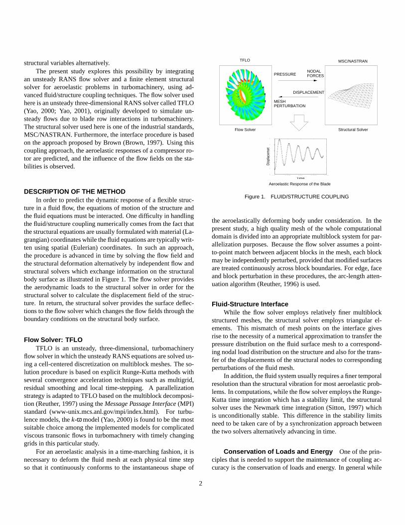
ture in a fluid flow, the equations of motion of the structure andthe fluid equations must be interacted. One difficulty in handlingthe fluid/structure coupling numerically comes from the fact thatthe structural equations are usually formulated with material (La-grangian) coordinates while the fluid equations are typically writ-ten using spatial (Eulerian) coordinates. In such an approach,the procedure is advanced in time by solving the flow field andthe structural deformation alternatively by independent flow andstructural solvers which exchange information on the structuralbody surface as illustrated in Figure 1. The flow solver providesthe aerodynamic loads to the structural solver in order for thestructural solver to calculate the displacement field of the struc-ture. In return, the structural solver provides the surface deflec-tions to the flow solver which changes the flow fields through theboundary conditions on the structural body surface.
Flow Solver: TFLOTFLO is an unsteady, three-dimensional, turbomachinery
flow solver in which the unsteady RANS equations are solved us-ing a cell-centered discretization on multiblock meshes. The so-lution procedure is based on explicit Runge-Kutta methods withseveral convergence acceleration techniques such as multigrid,residual smoothing and local time-stepping. A parallelizationstrategy is adapted to TFLO based on the multiblock decomposi-tion (Reuther, 1997) using theMessage Passage Interface(MPI)standard (www-unix.mcs.anl.gov/mpi/index.html). For turbu-lence models, thek-ω model (Yao, 2000) is found to be the mostsuitable choice among the implemented models for complicatedviscous transonic flows in turbomachnery with timely changinggrids in this particular study.
For an aeroelastic analysis in a time-marching fashion, it isnecessary to deform the fluid mesh at each physical time stepso that it continuously conforms to the instantaneous shape of
Aeroelastic Response of the Blade
Flow Solver Structural Solver
0 0.005 0.01 0.015 0.020.11
0.12
0.13
0.14
0.15
0.16
0.17
Time
Dis
plac
emet
PRESSURE
DISPLACEMENT
TFLO
FORCESNODAL
MESHPERTURBATION
MSC/NASTRAN
Figure 1. FLUID/STRUCTURE COUPLING
the aeroelastically deforming body under consideration. In thepresent study, a high quality mesh of the whole computationaldomain is divided into an appropriate multiblock system for par-allelization purposes. Because the flow solver assumes a point-to-point match between adjacent blocks in the mesh, each blockmay be independently perturbed, provided that modified surfacesare treated continuously across block boundaries. For edge, faceand block perturbation in these procedures, the arc-length atten-uation algorithm (Reuther, 1996) is used.
Fluid-Structure InterfaceWhile the flow solver employs relatively finer multiblock
structured meshes, the structural solver employs triangular el-ements. This mismatch of mesh points on the interface givesrise to the necessity of a numerical approximation to transfer thepressure distribution on the fluid surface mesh to a correspond-ing nodal load distribution on the structure and also for the trans-fer of the displacements of the structural nodes to correspondingperturbations of the fluid mesh.
In addition, the fluid system usually requires a finer temporalresolution than the structural vibration for most aeroelastic prob-lems. In computations, while the flow solver employs the Runge-Kutta time integration which has a stability limit, the structuralsolver uses the Newmark time integration (Sitton, 1997) whichis unconditionally stable. This difference in the stability limitsneed to be taken care of by a synchronization approach betweenthe two solvers alternatively advancing in time.
Conservation of Loads and Energy Oneof the prin-ciples that is needed to support the maintenance of coupling ac-curacy is the conservation of loads and energy. In general while
2

the fluidsystemaddresses the pressure field on the cell surfaceson the interface, the structural system is solved based on a set ofconcentrated forces at the nodes on the interface. A distributedpressure load, therefore, must be first transfered into equivalentnodal forces. Such a transformation must satisfy two require-ments. One is that the nodal forces must yield the same net forcesas the original distributed pressure loads do. Thus,
∑m
f(m) =Z
∂ΩpdS, (1)
wheref(m) is the nodal force vector at the nodem in the structure,and p is the pressure distribution on the surface∂Ω whose pro-jected area vector isS. The second requirement states the main-tenance of a proper energy balance. Equating the virtual workperformed byf(m) working on a virtual nodal displacementδq(m)
and that byp moving through the equivalent distributed virtualdisplacementδµµµ, the second requirement is given as follows,
∑m
f(m)δq(m) =Z
∂ΩpδµµµdS. (2)
In this study, the approach by Brown (Brown, 1997) is cho-sen to ensure that the transfer of the pressure fields to the nodalforces is both consistent and conservative. Brown’s approach canalso be used in the extrapolation of the nodal displacement in thestructural system to the mesh deformation on the surface of thefluid system as explained in the following section.
Deformation Tracking System Consider one of a setof finite elements describing a structural model and a fluid meshpoint on the blade surface shown in Figure 2. Letx denote theclosest point on the closest element from a fluid mesh pointX,it can be assumed that the vector connecting both points remainperpendicular to the element after deformation. Then, the dis-placementsµµµ(X) and rotationsµµµθ(X) at X can be expressed asfollows,
µµµ(X) = u(x)− (X−x)×uθ(x), µµµθ(X) = uθ(x), (3)
whereu(x) anduθ(x) are the displacement and rotation atx. Infinite element analysis, the displacement at any point within thedomain of an element in the model can be determined by theassumed interpolation functions in terms of the nodal displace-ments on the element. However, since MSC/NASTRAN is usedas a structural solver and the interpolation function used in it is
z
y
x
µ (X)DEFORM
u(x)
q , q , q1 2 3
q , q , q
q , q , q
1 2 3
7 8 9
13 14 15
A
A
A
1
2
3
Fluid Mesh Point
Finite Element
X
x
Figure 2. DEFORMATION TRACKING SYSTEM
unknown, all of the finite elements were assumed to use the sim-ple standard iso-parametric interpolation function based on thearea coordinate as the weighting (Reuther, 1999). WhenX isassociated withx on them-th element whose displacements are
denoted asq(m), this interpolation functionη(m) andη(m)θ can be
expressed as,
u(x) =[η(m)(x)
]·q(m), uθ(x) =
[η(m)
θ (x)]·q(m). (4)
The displacements at any point on the fluid mesh surface can thusbe written as,
µµµ(X) =[η(m)(x)
]·q(m)− [X−x] ·
[η(m)
θ (xn)]·q(m), (5)
where, the matrix[X − x] is in cross product form. Introduc-ing the displacement extrapolation functionsN(X) based on theglobal nodal displacementsq of the structural model, Equation 5can be rewritten usingq becauseq(m) is a part ofq.
µµµ(X) = [[η(x)]− [X−x] · [ηθ(x)]] ·q = [N(X)] ·q (6)
Load Transfer System For a load transfer algorithm,it is required to satisfy the conservation of load and energy ex-pressed in Equations 1 and 2, respectively. In Equation 2,δµµµ(X)can be related withδq introducing a set of assumed displacementinterpolation functionsN(X) given in Equation 6. SubstitutingEquation 6 into Equation 2 yields,
f ·δq = ∑m
f(m)δq(m) =Z
∂Ωp· [N(X)] δqdS, (7)
3
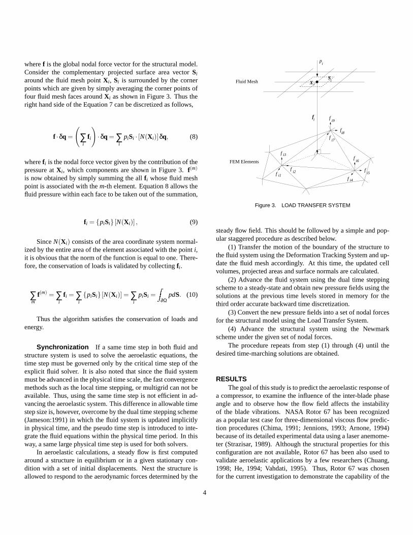
wheref is theglobalnodal force vector for the structural model.Consider the complementary projected surface area vectorSi
around the fluid mesh pointX i , Si is surrounded by the cornerpoints which are given by simply averaging the corner points offour fluid mesh faces aroundX i as shown in Figure 3. Thus theright hand side of the Equation 7 can be discretized as follows,
f ·δq =
(∑i
f i
)·δq = ∑
ipiSi · [N(X i)]δq, (8)
wheref i is the nodal force vector given by the contribution of thepressure atX i , which components are shown in Figure 3.f(m)
is now obtained by simply summing the allf i whose fluid meshpoint is associated with them-th element. Equation 8 allows thefluid pressure within each face to be taken out of the summation,
f i = piSi [N(X i)] , (9)
SinceN(X i) consists of the area coordinate system normal-ized by the entire area of the element associated with the pointi,it is obvious that the norm of the function is equal to one. There-fore, the conservation of loads is validated by collectingf i .
∑m
f(m) = ∑i
f i = ∑i
piSi [N(X i)] = ∑i
piSi =Z
∂ΩpdS. (10)
Thus the algorithm satisfies the conservation of loads andenergy.
Synchronization If a same time step in both fluid andstructure system is used to solve the aeroelastic equations, thetime step must be governed only by the critical time step of theexplicit fluid solver. It is also noted that since the fluid systemmust be advanced in the physical time scale, the fast convergencemethods such as the local time stepping, or multigrid can not beavailable. Thus, using the same time step is not efficient in ad-vancing the aeroelastic system. This difference in allowable timestep size is, however, overcome by the dual time stepping scheme(Jameson:1991) in which the fluid system is updated implicitlyin physical time, and the pseudo time step is introduced to inte-grate the fluid equations within the physical time period. In thisway, a same large physical time step is used for both solvers.
In aeroelastic calculations, a steady flow is first computedaround a structure in equilibrium or in a given stationary con-dition with a set of initial displacements. Next the structure isallowed to respond to the aerodynamic forces determined by the
FEM Elements
Fluid Mesh
p
S
f f
f
f
f
f
f
f
f
f
i
i
i i9
i8
i1i2
i3
i4
i5
i6
i7
iX
Figure 3. LOAD TRANSFER SYSTEM
steady flow field. This should be followed by a simple and pop-ular staggered procedure as described below.
(1) Transfer the motion of the boundary of the structure tothe fluid system using the Deformation Tracking System and up-date the fluid mesh accordingly. At this time, the updated cellvolumes, projected areas and surface normals are calculated.
(2) Advance the fluid system using the dual time steppingscheme to a steady-state and obtain new pressure fields using thesolutions at the previous time levels stored in memory for thethird order accurate backward time discretization.
(3) Convert the new pressure fields into a set of nodal forcesfor the structural model using the Load Transfer System.
(4) Advance the structural system using the Newmarkscheme under the given set of nodal forces.
The procedure repeats from step (1) through (4) until thedesired time-marching solutions are obtained.
RESULTSThe goal of this study is to predict the aeroelastic response of
a compressor, to examine the influence of the inter-blade phaseangle and to observe how the flow field affects the instabilityof the blade vibrations. NASA Rotor 67 has been recognizedas a popular test case for three-dimensional viscous flow predic-tion procedures (Chima, 1991; Jennions, 1993; Arnone, 1994)because of its detailed experimental data using a laser anemome-ter (Strazisar, 1989). Although the structural properties for thisconfiguration are not available, Rotor 67 has been also used tovalidate aeroelastic applications by a few researchers (Chuang,1998; He, 1994; Vahdati, 1995). Thus, Rotor 67 was chosenfor the current investigation to demonstrate the capability of the
4
previouslydescribednonlinear aeroelastic prediction procedure.NASA Rotor 67 consists of 22 blades. The blade aspect ratiois 1.56. At the design point, the rotational speed of the rotor is16,043 RPM, with a tip inlet relative Mach number of 1.38, atotal pressure ratio of 1.63 and a mass flow of 33.25 Kg/s.
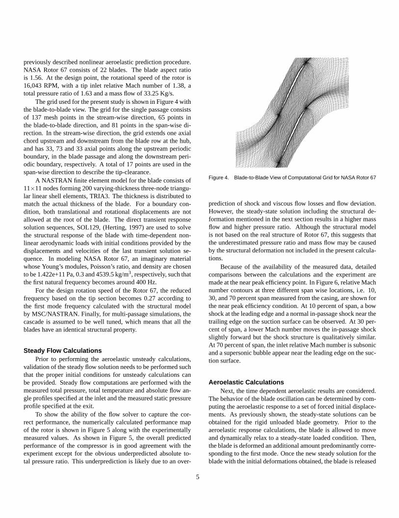
The grid used for the present study is shown in Figure 4 withthe blade-to-blade view. The grid for the single passage consistsof 137 mesh points in the stream-wise direction, 65 points inthe blade-to-blade direction, and 81 points in the span-wise di-rection. In the stream-wise direction, the grid extends one axialchord upstream and downstream from the blade row at the hub,and has 33, 73 and 33 axial points along the upstream periodicboundary, in the blade passage and along the downstream peri-odic boundary, respectively. A total of 17 points are used in thespan-wise direction to describe the tip-clearance.
A NASTRAN finite element model for the blade consists of11×11 nodes forming 200 varying-thickness three-node triangu-lar linear shell elements, TRIA3. The thickness is distributed tomatch the actual thickness of the blade. For a boundary con-dition, both translational and rotational displacements are notallowed at the root of the blade. The direct transient responsesolution sequences, SOL129, (Herting, 1997) are used to solvethe structural response of the blade with time-dependent non-linear aerodynamic loads with initial conditions provided by thedisplacements and velocities of the last transient solution se-quence. In modeling NASA Rotor 67, an imaginary materialwhose Young’s modules, Poisson’s ratio, and density are chosento be 1.422e+11 Pa, 0.3 and 4539.5 kg/m3, respectively, such thatthe first natural frequency becomes around 400 Hz.
For the design rotation speed of the Rotor 67, the reducedfrequency based on the tip section becomes 0.27 according tothe first mode frequency calculated with the structural modelby MSC/NASTRAN. Finally, for multi-passage simulations, thecascade is assumed to be well tuned, which means that all theblades have an identical structural property.
Steady Flow CalculationsPrior to performing the aeroelastic unsteady calculations,
validation of the steady flow solution needs to be performed suchthat the proper initial conditions for unsteady calculations canbe provided. Steady flow computations are performed with themeasured total pressure, total temperature and absolute flow an-gle profiles specified at the inlet and the measured static pressureprofile specified at the exit.
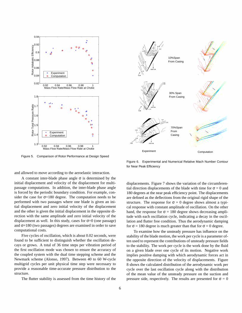
To show the ability of the flow solver to capture the cor-rect performance, the numerically calculated performance mapof the rotor is shown in Figure 5 along with the experimentallymeasured values. As shown in Figure 5, the overall predictedperformance of the compressor is in good agreement with theexperiment except for the obvious underpredicted absolute to-tal pressure ratio. This underprediction is likely due to an over-
Figure 4. Blade-to-Blade View of Computational Grid for NASA Rotor 67
prediction of shock and viscous flow losses and flow deviation.However, the steady-state solution including the structural de-formation mentioned in the next section results in a higher massflow and higher pressure ratio. Although the structural modelis not based on the real structure of Rotor 67, this suggests thatthe underestimated pressure ratio and mass flow may be causedby the structural deformation not included in the present calcula-tions.
Because of the availability of the measured data, detailedcomparisons between the calculations and the experiment aremade at the near peak efficiency point. In Figure 6, relative Machnumber contours at three different span wise locations, i.e. 10,30, and 70 percent span measured from the casing, are shown forthe near peak efficiency condition. At 10 percent of span, a bowshock at the leading edge and a normal in-passage shock near thetrailing edge on the suction surface can be observed. At 30 per-cent of span, a lower Mach number moves the in-passage shockslightly forward but the shock structure is qualitatively similar.At 70 percent of span, the inlet relative Mach number is subsonicand a supersonic bubble appear near the leading edge on the suc-tion surface.
Aeroelastic CalculationsNext, the time dependent aeroelastic results are considered.
The behavior of the blade oscillation can be determined by com-puting the aeroelastic response to a set of forced initial displace-ments. As previously shown, the steady-state solutions can beobtained for the rigid unloaded blade geometry. Prior to theaeroelastic response calculations, the blade is allowed to moveand dynamically relax to a steady-state loaded condition. Then,the blade is deformed an additional amount predominantly corre-sponding to the first mode. Once the new steady solution for theblade with the initial deformations obtained, the blade is released
5
0.92 0.94 0.96 0.98 10.82
0.84
0.86
0.88
0.9
0.92
0.94
Mass Flow Rate/Mass Flow Rate at Choke
Rot
or A
diab
atic
Effi
cien
cy
ExperimentComputation
0.92 0.94 0.96 0.98 11.3
1.4
1.5
1.6
1.7
1.8
Mass Flow Rate/Mass Flow Rate at Choke
Rot
or T
otal
Pre
ssur
e R
atio
ExperimentComputation
Figure 5. Comparison of Rotor Performance at Design Speed
and allowed to move according to the aeroelastic interaction.A constant inter-blade phase angleσ is determined by the
initial displacement and velocity of the displacement for multi-passage computations. In addition, the inter-blade phase angleis forced by the periodic boundary condition. For example, con-sider the case forσ=180 degree. The computation needs to beperformed with two passages where one blade is given an ini-tial displacement and zero initial velocity of the displacementand the other is given the initial displacement in the opposite di-rection with the same amplitude and zero initial velocity of thedisplacement as well. In this study, cases forσ=0 (one passage)andσ=180 (two passages) degrees are examined in order to savecomputational costs.
Five cycles of oscillation, which is about 0.02 seconds, werefound to be sufficient to distinguish whether the oscillation de-cays or grows. A total of 36 time steps per vibration period ofthe first oscillation mode was chosen to ensure the accuracy ofthe coupled system with the dual time stepping scheme and theNewmark scheme (Alonso, 1997). Between 40 to 60 W-cyclemultigrid cycles per unit physical time step were necessary toprovide a reasonable time-accurate pressure distribution to thestructure.
The flutter stability is assessed from the time history of the
0.9003
1.0804
0.76526
1.3593
1.40
31
1.0086
1.2062
1.3785
0.86159
From Casing10%Span
30% SpanFrom Casing
70%SpanFromCasing
Experiment Computation
Figure 6. Experimental and Numerical Relative Mach Number Contour
for Near Peak Efficiency
displacements. Figure 7 shows the variation of the circumferen-tial direction displacements of the blade with time forσ = 0 and180 degrees at the near peak efficiency point. The displacementsare defined as the deflections from the original rigid shape of thestructure. The response forσ = 0 degree shows almost a typi-cal response with constant amplitude of oscillation. On the otherhand, the response forσ = 180 degree shows decreasing ampli-tude with each oscillation cycle, indicating a decay in the oscil-lation and flutter free condition. Thus the aerodynamic dampingfor σ = 180 degree is much greater than that forσ = 0 degree.
To examine how the unsteady pressure has influence on thestability of the blade motion, the work per cycle is a parameter of-ten used to represent the contributions of unsteady pressure fieldsto the stability. The work per cycle is the work done by the fluidon a given blade over one cycle of its motion. Negative workimplies positive damping with which aerodynamic forces act inthe opposite direction of the velocity of displacements. Figure8 shows the calculated distribution of the aerodynamic work percycle over the last oscillation cycle along with the distributionof the mean value of the unsteady pressure on the suction andpressure side, respectively. The results are presented forσ = 0
6

0 0.005 0.01 0.0152.5
3
3.5
4
x 10−3ω = 16043[rpm], P2/P1 = 1.63
Time [sec.]
Dis
plac
emet
[m]
0 0.005 0.01 0.0152.5
3
3.5
4
x 10−3ω = 16043[rpm], P2/P1 = 1.63
Time [sec.]
Dis
plac
emet
[m]
Figure 7. DEFLECTION AT MID-CHORD OF THE TIP SECTION FOR
NEAR PEAK EFFICIENCY, σ = 0,180deg
degrees. As shown, significant work per cycle magnitudes existin the region where the shocks sit on the blade. On the suctionside, the shock appears along the entire span as a continuous line.However, a negative peak in the work per cycle distribution ap-pears only at the location where the lower part of the shock sits onthe suction side. Between the casing and 40 percent of the span,the passage shock is very strong and indicates that an adversepressure gradient follows that may cause shock induced separa-tion. On the other hand, below 40 percent of span, the shock isformed inside the supersonic bubble and does not reach the pres-sure side of the adjacent blade as seen in the Mach contour atthe 70 percent span in Figure 6. Therefore, only the lower shockoscillation works to dampens the blade motion. On the pressureside, there is a positive peak near the location of the in-passageshock. Notice that the regions of exciting and damping forceson both sides are quite close. That means that the exciting anddamping forces generated by the shock oscillations cancel eachother resulting in an almost constant amplitude motion.
Figure 9 shows the mean pressure and work per cycle dis-tributions forσ = 180 degrees. For this case, the two kinds ofshocks on the suction side mentioned above do not form a con-tinuous line. The forces generated by the in-passage shock onthe suction side works to dampen the oscillation, while the peaksalong the oblique shock and the lower part of the shock disap-pear. Is is also obvious that the in-passage shock on the pressureside produces the large damping forces toward the leading edge.Thus the physical mechanism for the decaying response ofσ =180 case is clearly explained. A similar argument about the trendwith inter-blade phase angle is reported by Chuang (Chuang,1998) for the same configuration though the reduced frequencyis different.
CONCLUSIONSA fluid/structure coupled aeroelastic solver for turboma-
chinery based on a three-dimensional unsteady RANS solver,TFLO, and the finite element structural analysis package,MSC/NASTRAN, was developed for use in turbomachinery flut-ter simulations. The capabilities of the solver are demonstrated
(b) Work per Cycle − Suction Side
(d) Work per Cycle − Pressure Side(c) Mean Pressure − Pressure Side
(a) Mean Pressure − Suction Side
supersonic bubbleShock in
In−passage shockpropagates fromthe suction side
In−passage shock
In−passage shock
Figure 8. MEAN PRESSURE AND WORK PER CYCLE DISTRIBUTION
ON THE BLADE SURFACES FOR NEAR PEAK EFFICIENCY, σ = 0deg
by applying it to investigate the aeroelastic response character-istics of a transonic fan rotor, NASA Rotor 67. The aeroelas-tic solver successfully produces different time history of bladedisplacements for turbomachinery depending on conditions. Re-sults presented for Rotor 67 revealed that the main contributionto the stability of a transonic fan is the unsteady forces gener-ated by the shock motions. In determining these shock motions,inter-blade phase angles play the most important role.
One of the biggest concern for these fluid/structure compu-tations is that the coupled procedure is still computationally ex-pensive. Advanced engines, however, will likely require aeroe-lastic analysis for multiple blade rows, or a whole wheel sys-tem to admit all possible frequencies and inter-blade phase an-gles. Fluid/structure couplings such as presented here would con-tribute to these kind of numerical predictions for aeroelasticallysevere conditions. Furthermore, one of the biggest benefit of thenumerical analysis is its richness in data that the experiment hasbeen lacking due the difficulties in installing the measurementinstruments.
7

(b) Work per Cycle − Suction Side
(d) Work per Cycle − Pressure Side
(a) Mean Pressure − Suction Side
(c) Mean Pressure − Pressure Side
supersonic bubbleShock in
In−passage shock
Oblique shock
Figure 9. MEAN PRESSURE AND WORK PER CYCLE DISTRIBU-
TION ON THE BLADE SURFACES FOR NEAR PEAK EFFICIENCY,
σ = 180deg
REFERENCESAlonso, J. J., Parallel Computations of Unsteady and Aeroe-
lastic Flow Using an Implicit Multigrid-Driven Algorithm, Ph.D.Thesis, Princeton University, 1997
Arnone, A., Viscous Analysis of Three-Dimensional RotorFlow Using a Multigrid Method,Journal of Turbomachinery,Vol.116, No.3, 1994
Bakhle, M. A., Srivastava R., Keith Jr., T. G. and Stefko, G.L., A 3D Euler/Navier-Stokes Aeroelastic Code for PropulsionApplications, AIAA-97-2749, 1997
Brown, S. A., Displacement extrapolations for CFD+CSMaeroelastic analysis, AIAA-97-1090, 1997
Chew, J. W., Marshall, J. G., Vahdati, M. and Imregun,M., Part-Speed Flutter Analysis of a Wide-Chord Fan Blade,Unsteady Aerodynamics and Aeroelasticity of Turbomachines,Kluwer Academic Publisher, 1998
Chima, R. V., Viscous Three-Dimensional Calculations ofTransonic Fan Performance, NASA-TM-103800, 1991
Chuang, H. A. and Verdon, J. M., A Numerical Simulatorfor Three-Dimensional Flows Through Vibrating Blade Rows,NASA-CR-1998-208511, 1998
Gerolymos, G. A., Advances in the Numerical Integration ofthe Three-Dimensional Euler Equations in Vibrating Cascades,Journal of Turbomachinery, Vol.115, No.4, 1993
Hall, K. C. and Lorence, C. B., Calculation of Three Dimen-sional Unsteady Flows in Turbomachinery Using the LinearizedHarmonic Euler Equations,Journal of Turbomachinery, Vol.115,No.4, 1993
He, L. and Denton. J. D., Three-Dimensional Time-Marching Inviscid and Viscous Solutions for Unsteady FlowsAround Vibrating Blades,Journal of Turbomachinery, Vol.116,No.3, 1994
Herting, D. N.,MSC/NASTRAN Advanced Dynamic Analy-sis User’s Guide, MacNeal-Schwendler Corporation, 1997
Jameson, A., Time Dependant Calculations Using Multigridwith Applications to Unsteady Flows Past Airfoils and Wings,AIAA-91-1596, 1991
Jennions, I. K. and Turner, M. G., Three-DimensionalNavier-Stokes Computations of Transonic Fan Flow Using anExplicit Flow Solver and an Implicit k-ω Solver,Journal of Tur-bomachinery, Vol.115, No.1, 1993
Ji, S. and Liu, F., Flutter Computation of TurbomachineryCascades Using a Parallel Unsteady Navier-Stokes Code,AIAAJournal, Vol.37, No.3, 1999
Ning, W. and He, L., Computation of Unsteady FlowsAround Oscillating Blades Using Linear and Nonlinear Har-monic Euler Methods,Journal of Turbomachinery, Vol.120,No.3, 1998
Reuther, J. J., Jameson, A., Farmer, J., Martinelli, L. andSaunders, D., Aerodynamic Shape Optimization of ComplexAircraft Configurations via an Adjoint Formulation, AIAA-96-0094, 1996
Reuther, J. J., Alonso, J. J., Vassberg, J. C., Jameson, A. andMartinelli, L., An Efficient Multiblock Method for AerodynamicAnalysis and Design on Distributed Memory Systems, AIAA-97-1893, 1997
Reuther, J. J., Alonso, J. J., Martins, J. R. R. A. and Smith, S.C., A Coupled Aero-Structural Optimization Method For Com-plete Aircraft Configurations, AIAA-99-0187, 1999
Sitton, G.,MSC/NASTRAN Basic Dynamic Analysis User’sGuide, MacNeal-Schwendler Corporation, 1997
Strazisar, A. J., Wood, J. R., Hathaway, M. D. and Suder, K.L., Laser Anemometer Measurements in a Transonic Axial-FlowFan Rotor, NASA-TP-2879, 1989
Vahdati, M. and Imregun, M., Non-linear AeroelasticityAnalysis Using Unstructured Dynamics Meshes,Unsteady Aero-dynamics and Aeroelasticity of Turbomachines, Elsevier, 1995
Yao, J., Jameson, A., Alonso, J. J. and Liu, F., Developmentand Validation of a Massively Parallel Flow Solver for Turboma-chinery Flows, AIAA-00-0882, 2000
Yao, J., Davis, R. L., Alonso, J. J. and Jameson, A., Un-steady Flow Investigations in an Axial Turbine Using the Mas-sively Parallel Flow Solver TFLO, AIAA-2001-0529, 2001
8