fluid mechanics class notes -dr.t.rangas wamy, mce, hassan
TRANSCRIPT

Fluid dynamics:
Introduction:
The laws of Statics that we have learned cannot solve Dynamic Problems. There is no way to
solve for the flow rate, or Q. Therefore, we need a new dynamic approach to Fluid Mechanics.
Equations of Motion
The dynamics of fluid flow is the study of fluid motion with forces causing flow. The dynamic
behaviors of the fluid flow is analyzed by the Newton’s law of motion (F=ma), which relates
the acceleration with the forces. The fluid is assumed to be incompressible and non-viscous.
Mathematically, Fx = m.ax
In the fluid flow, following forces are present:
• pressure force ‘Fp’
• gravity force ‘Fg’
• viscous force ‘Fv’
• turbulent flow ‘Ft’
• surface tension force ‘Fs’
• compressibility force ‘Fe’
• The pressure force ‘Fp’ is exerted on the fluid mass, if there exists a pressure gradient
between the 2 parts in the direction of flow.

• The gravity force ‘Fg’ is due to the weight of the fluid and it is equal to ‘Mg’. The
gravity force for unit volume is equal to ‘ρg’.
• The viscous force ‘Fv’ is due to the viscosity of the flowing fluid and thus exists in the
case of all real fluid.
• The turbulent flow ‘Ft’ is due to the turbulence of the flow. In the turbulent flow, the
fluid particles move from one layer to other and therefore, there is a continuous
momentum transfer between adjacent layer, which results in developing additional
stresses(called Reynolds stresses) for the flowing fluid.
• The surface tension force ‘Fs’ is due to the cohesive property of the fluid mass. It is,
however, important only when the depth of flow is extremely small.
• The compressibility force ‘Fe’ is due to elastic property of fluid and it is important only
either for compressible fluids or in the cases of flowing fluids in which the elastic
properties of fluids are significant.
• If a certain mass of fluid in the motion is influenced by all the above mentioned forces,
thus according to Newton’s law of motion, the following equation of motion may be
written as
M a = Fg+ Fp+ Fv+ Ft+ Fs+ Fe =net force Fx ---- (1)
Further by resolving the various forces and the acceleration along the x, y and z directions, the
following equation of motion may be obtained.
Max= Fgx +Fpx +Fvx+ Ftx+Fsx+Fex
May= Fgy+Fpy+Fvy+Fty+Fsy+Fey ---- (1a)
Maz= Fgz+Fpz+Fvz+Ftz+Fsz+Fez
The subscripts x, y and z are introduced to represent the component of each of the forces and the
acceleration in the respective directions.

In most of the problems of the fluids in motion, the tension forces and the compressibility
forces are not significant. Hence, the forces may be neglected, thus equations (1) and (1a)
became.
Ma= Fg+Fp+Fv+Ft --- (2)
And
Max= Fgx+Fpx+Fvx+Ftx
May= Fgy+Fpy+Fvy+Fty --- (2a)
Maz= Fgz+Fpz+Fvz+Ftz
Equations (2a) are known as Reynolds’s equations of motion which are useful in the analysis
of the turbulent flows. Further, for laminar or viscous flows the turbulent forces are less
significant and hence they may be neglected. The eqns.(2) & (2a) may then be modified as,
Ma= Fg+Fp+Fv
And
Max = Fgx+Fpx+Fvx
May = Fgy+Fpy+Fvy ---- (3a)
Maz = Fgz+Fpz+Fvz
Equations (3a) are known as Navier-stokes equations which are useful in the analysis of
viscous flow. Further, if the viscous forces are also of less significance in the problems of fluid
flows, then these force may also neglected. The viscous forces will become insignificant if the
flowing fluid is an ideal fluid. However, in case of real fluids, the viscous forces may be
considered insignificant if the viscosity of flowing fluid is small. In such cases the eqn.(3)&(3a)
may be further modified as
Ma= Fg+ Fp ------ (4)
And
Max = Fgx+ Fpx
May = Fgy+ Fpy ------- (4a)

Maz = Fgz+ Fpz
Equation (4a) is known as Euler's equation of motion.
Euler's equation of motion:
Statement: In an ideal incompressible fluid, when the flow is steady and continuous, sum of
the velocity head, pressure head and datum head along a stream line is constant.
Assumptions:
• The fluid is ideal and incompressible.
• Flow is steady and continuous.
• Flow is along streamline and it is 1-D.
• The velocity is uniform across the section and is equal to the mean velocity.
• Flow is Irrotational.
• The only forces acting on the fluid are gravity and the pressure forces.

Consider a streamline and select a small cylindrical fluid system for analysis as shown in Figs.
1(a) & (b) of length ‘ds’ and c/s area ‘dA’ as a free body from the moving fluid,
Let, p = pressure on the element at ‘L’
p+dp = pressure on the element at M and
v= velocity of the fluid element.
The forces acting (tending to accelerate) the fluid element in the direction of stream line are as
follows,
1) Net pressure force in the direction of flow is
p.dA-(p+dp) dA= - dp.dA ------- (1)
2) Component of the weight of the fluid element in the direction of flow is
= - ρg.dA.ds.cosθ
= - ρg.dA.ds (dz/ds) (because cosθ=dz/ds)
= - ρg.dA.dz -- (2)
Mass of the fluid element = ρ.dA.ds -- (3)
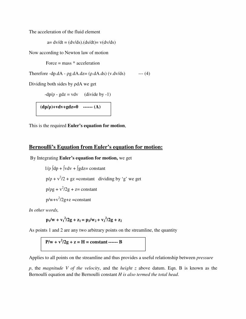
The acceleration of the fluid element
a= dv/dt = (dv/ds).(ds/dt)= v(dv/ds)
Now according to Newton law of motion
Force = mass * acceleration
Therefore -dp.dA - ρg.dA.dz= (ρ.dA.ds) (v.dv/ds) --- (4)
Dividing both sides by ρdA we get
-dp/ρ - gdz = vdv (divide by -1)
This is the required Euler’s equation for motion,
Bernoulli’s Equation from Euler’s equation for motion:
By Integrating Euler’s equation for motion, we get
1/ρ ∫dp + ∫vdv + ∫gdz= constant
p/ρ + v2/2 + gz =constant dividing by ‘g’ we get
p/ρg + v2/2g + z= constant
p/w+v2/2g+z =constant
In other words,
p1/w + v12/2g + z1 = p2/w2 + v2
2/2g + z2
As points 1 and 2 are any two arbitrary points on the streamline, the quantity
Applies to all points on the streamline and thus provides a useful relationship between pressure
p, the magnitude V of the velocity, and the height z above datum. Eqn. B is known as the
Bernoulli equation and the Bernoulli constant H is also termed the total head.
(dp/ρ)+vdv+gdz=0 ------ (A)
P/w + v2/2g + z = H = constant ------ B
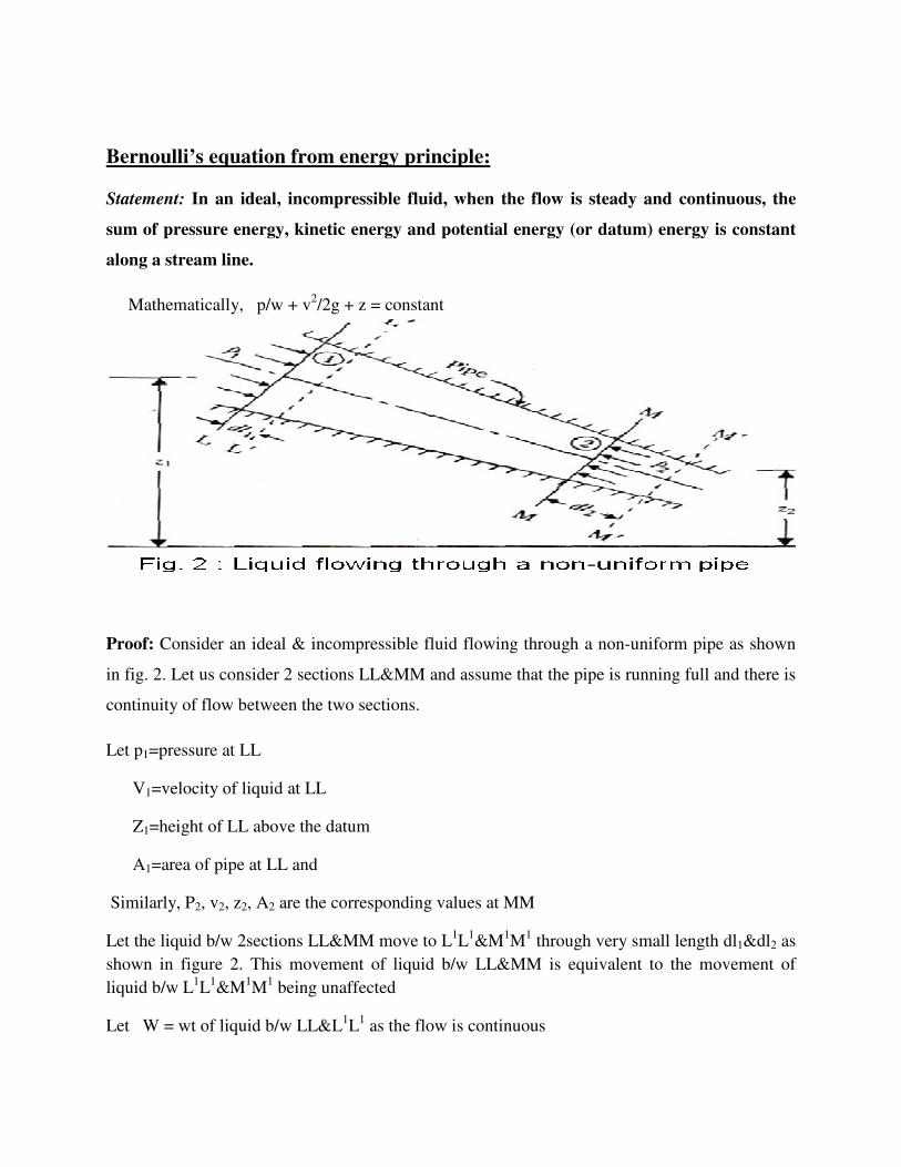
Bernoulli’s equation from energy principle:
Statement: In an ideal, incompressible fluid, when the flow is steady and continuous, the
sum of pressure energy, kinetic energy and potential energy (or datum) energy is constant
along a stream line.
Mathematically, p/w + v2/2g + z = constant
Proof: Consider an ideal & incompressible fluid flowing through a non-uniform pipe as shown
in fig. 2. Let us consider 2 sections LL&MM and assume that the pipe is running full and there is
continuity of flow between the two sections.
Let p1=pressure at LL
V1=velocity of liquid at LL
Z1=height of LL above the datum
A1=area of pipe at LL and
Similarly, P2, v2, z2, A2 are the corresponding values at MM
Let the liquid b/w 2sections LL&MM move to L1L1&M1M1 through very small length dl1&dl2 as
shown in figure 2. This movement of liquid b/w LL&MM is equivalent to the movement of
liquid b/w L1L1&M1M1 being unaffected
Let W = wt of liquid b/w LL&L1L1 as the flow is continuous

W= wA1dl1=wA2dl2 … Volume of fluid
Or A1dl1=W/w and A2dl2=W/w
Therefore A1dl1=A2dl2
Work done by press at LL in moving the liquid to L1L1= force * distance=p1A1dl1
Similarly, work done by press at MM in moving the liquid to M1M1= P2A2dl2 (negative sign
indicates that direction of p2 is opposite to that of p1)
Therefore, work done by the pressure
=p1A1dl1- p2A2dl2
=p1A1dl1-p2A2dl2 (because A1dl1=A2dl2)
=A1dl1 (p1-p2)
=W/w (p1-p2) (because A1dl1=W/w)
Loss of potential energy (PE) = W (Z1-Z2)
Gain of kinetic energy (KE) = W (v22/2g-v1
2/2g) = W/2g(v22-v1
2)
Also, loss of P.E+ work done by pressure = gain in K.E
Therefore W (z1-z2) +W/w (p1-p2) =W/2g (v22-v1
2)
or (z1-z2) +(p1/w-p2/w)=(v22/2g-v1
2/2g)
P1/w+v12/2g+z1=p2/w+v2
2/2g+z2
Which prove Bernoulli's equation
P/w = pressure energy per unit weight
= pressure head
v2/2g = Kinetic energy per unit weight
= kinetic head
Z = datum energy per unit weight
= datum head

Bernoulli’s equation for real fluid:
Bernoulli’s equation earlier derived was based on the assumption that fluid is non viscous and
therefore frictionless. Practically, all fluids are real (and not ideal) and therefore are viscous and
as such always some losses in fluid flow. These losses have, therefore, to be taken into
consideration in the application of Bernoulli’s equation which gets modified (between sections 1
& 2) for real fluids as follows:
p1/w + v12/2g + z1 = p2/w + v2
2/2g + z2 + hL
Where
hL = loss of head/energy between sections1 & 2
26/27-3-2010
Problems on Bernoulli’s Equation:
1. Water is flowing through a pipe of diameter 5cm under a pressure of 29.43N/cm2 (gauge) and
with mean velocity of 2 m/s. Find the total energy per unit weight of the water at a cross-section,
which is 5m above the datum line.
Solution
Diameter of pipe = 5cm = 0.5 m
Pressure p = 29.43N/cm2 = 29.43 x 10⁴ N/m2
Datum head z =5m
Total head = pressure head + kinetic head+ datum head
Pressure head= p/ρg=29.43 x 104 /1000 x9.81 =30m
Kinetic head=v2/2g = 2x2/2x9.81= 0.204m
Total head= p/ρ g+ v2/2g+z = 30+0.204+5 = 35.204 m
2). A pipe through which the water is flowing, is having diameters 20 cm and 10 cm at the cross-
sections 1 and 2 respectively. The velocity of water at section 1 is given 40m/s. find the velocity
head at sections 1 and 2, and also rate of discharge.

Fig. 2
Solution
D1=20 cm =0.2m,
A1=π/4 x D12 = 0.0314 m2,
v1=4 m/s
D2=0.1m,
A2=π/4 x D22 = 0.00785 m2
Velocity head at section 1
V12/ 2g = 4 x4 /2x9.81=0.815 m
Velocity head at section 2 = V22/2g
To find V2, apply continuity equation at sections 1&2
A1V1=A2V2
V2= A2V2/A2= 0.0314 x4/0.00785 =16.0 m/s
Velocity head at sec.2 = V22/2g = 16 x16 /2 x9.81
V2 = 83.047 m
Rate of discharge = A1V1 or A2V2= 0.0314 x 4
=0.1256 m3/s
= 125.6 lit/s [1 m3 = 1000litres]
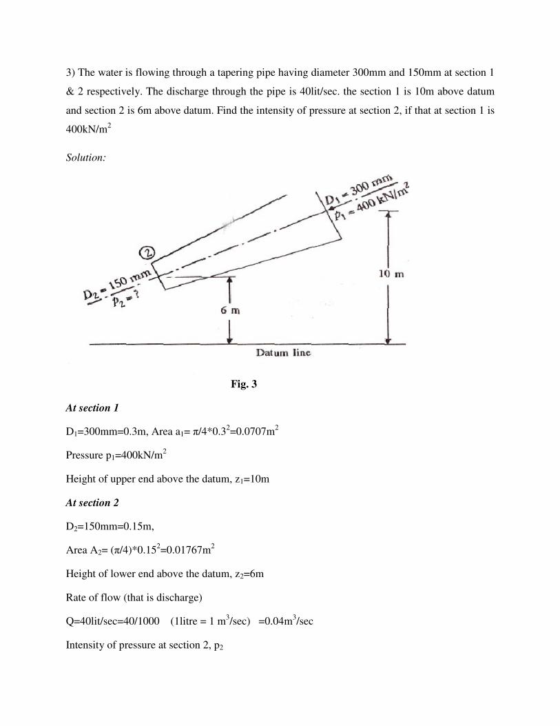
3) The water is flowing through a tapering pipe having diameter 300mm and 150mm at section 1
& 2 respectively. The discharge through the pipe is 40lit/sec. the section 1 is 10m above datum
and section 2 is 6m above datum. Find the intensity of pressure at section 2, if that at section 1 is
400kN/m2
Solution:
Fig. 3
At section 1
D1=300mm=0.3m, Area a1= π/4*0.32=0.0707m2
Pressure p1=400kN/m2
Height of upper end above the datum, z1=10m
At section 2
D2=150mm=0.15m,
Area A2= (π/4)*0.152=0.01767m2
Height of lower end above the datum, z2=6m
Rate of flow (that is discharge)
Q=40lit/sec=40/1000 (1litre = 1 m3/sec) =0.04m3/sec
Intensity of pressure at section 2, p2
As the flow is continuous, Q = A1V1= A2V2 (Continuity equation)
Therefore, V1= Q/A1 = 0.04/0.0707 = 0.566m/sec
And V2= Q/A2 = 0.04/0.01767 = 2.264m/sec
Apply Bernoulli’s equation at sections 1 & 2,
We get, p1/w+v12/2g+z1=p2/w+v2
2/2g+z2
And p2/w = p1/w + (v12-v2
2/2g) + z1-z2
= (400/9.81) + 1/ (2*9.81)*(0.5662-2.2642)+(10-6)
= 40.77- 0.245+4 (as w =ρ.g = 1000 x 9.81 N/m3)
= 44.525m = 9.81 kN/m3
P2 = 44.525 * w = 44.525 * 9.81 = 436.8 kN/m2
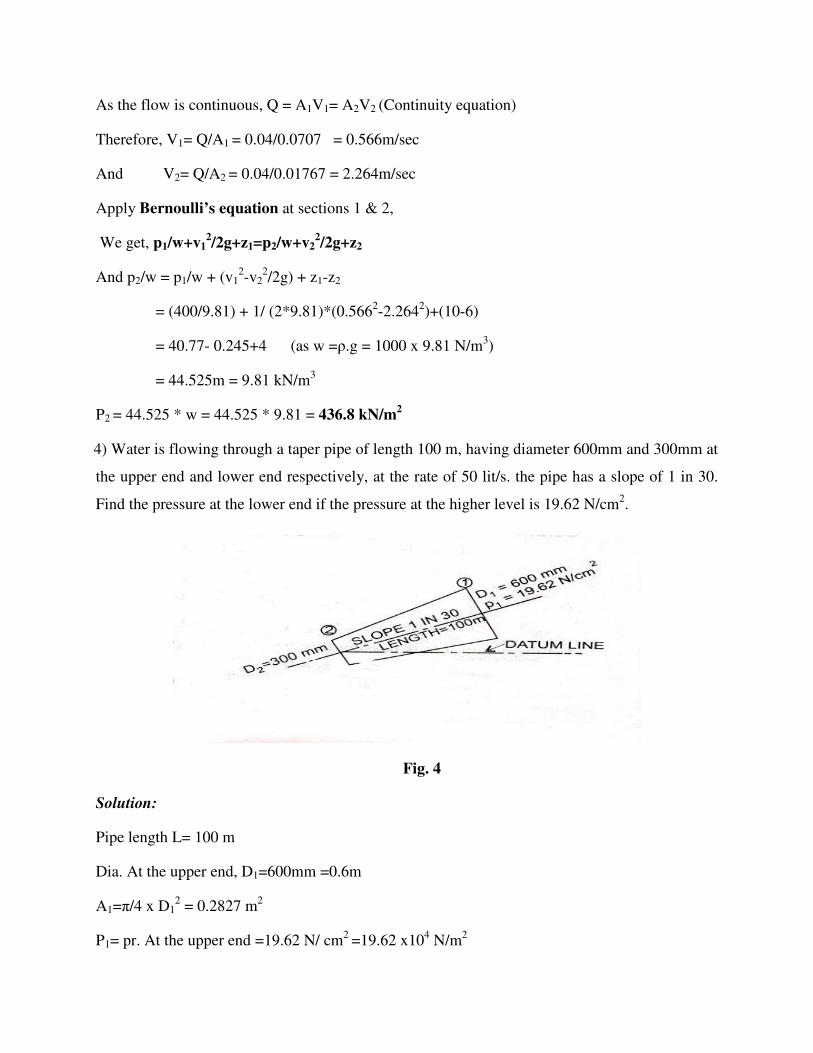
4) Water is flowing through a taper pipe of length 100 m, having diameter 600mm and 300mm at
the upper end and lower end respectively, at the rate of 50 lit/s. the pipe has a slope of 1 in 30.
Find the pressure at the lower end if the pressure at the higher level is 19.62 N/cm2.
Fig. 4
Solution:
Pipe length L= 100 m
Dia. At the upper end, D1=600mm =0.6m
A1=π/4 x D12 = 0.2827 m2
P1= pr. At the upper end =19.62 N/ cm2 =19.62 x10⁴ N/m2

Dia. At the lower end, D2=300mm =0.3m
A2=π/4 x D22 = 0.07068 m2
Rate of flow, Q =50 lit/s, Q=50/1000=0.05 m3/s
Let the datum line is passing through the centre of the lower end, Then z2=0
As slope is 1 in 30 means z1=1/30 x100= 10/3 m
Q= A1V1=A2V2
V1=0.05/A1 =0.1768=0.177 m/s
V2=0.05/A2=0.7074 =0.707 m/s
Applying Bernoulli’s equation at (1) and (2) we get
P1/ ρg + V12/ 2g +z1 = P2/ ρg + V2
2/ 2g +z2
19.62 x 10⁴/1000 x 9.81 + 0.1772 /2 x 9.81 + 3.334= P2/ ρg +0.7072/2 x 9.81+ 0
20 + 0.001596 + 3.334= P2/ ρg +0.0254
23.335 – 0.0254 = P2/ 1000 x9.81
P2 =228573 N/m2
= 22.857 N/cm2
5) A pipe 200m long slopes down at 1 in 100 and tapers from 600mm diameter at the higher end
to 300mm diameter at the lower end, and carries 100 lit/sec of oil (specific gravity 0.8). If the
pressure gauge at the higher end reads 60 kN/m2. Determine,
i. Velocities at both ends.
ii. Pressure at the lower end. Neglect the losses

Fig. 5
Solution:
Given: Length of the pipe, l= 200mm
Diameter of the pipe at the higher end,
D1 =600mm= 0.6m, Area, A1 = (π/4)*0.62 =0.283 m2
Diameter of the pipe at the lower end,
D2 =300mm= 0.3m, Area, A2 = (π/4)*0.32 = 0.0707 m2
Height of the lower end, above datum Z2 =0
Rate of oil flow, Q=100lit/sec= 0.1 m3/sec
Pressure at the higher end, p1 =60kN/m2
(i) Velocities, V1 & V2
Now Q=A1V1 = A2V2
Where V1 & V2 are the velocities at the higher and lower side respectively.
V1= Q/A1 =0.1/0.283= 0.353m/sec
V2= Q/A2=0.1/0.0707=1.414m/sec, and

(ii) Pressure at the lower end, p2
Using Bernoulli’s equation for both ends of pipe, we have
p1/w+v12/2g+z1=p2/w+v2
2/2g+z2
60/(0.8*9.81)+0.3532/(2*9.81)+2=p2/(0.8*9.81)+(1.4142/2*9.81)+0
p2 /(0.8*9.81) = 9.54,
Pressure at lower end, p2 = 74.8 kN/m2
6) Water is flowing through a pipe having diameter 300mm and 200mm at the bottom and upper
end respectively. The intensity of pressure at the bottom end is 24.525 N/cm2 and at upper end is
9.81 N/cm2. Determine the difference in datum head if the rate of flow through pipe is 40 lit/s.
Fig. 6
Solution:
At Section (1), D1=300mm =0.3m
P1=24.525 N/cm2 =24.525 x 10⁴ N/m2
Rate of flow = 40 lit/sec, Q=40/1000=0.04 m3/s
Now A1V1=A2V2=0.04
V1=0.04/A1 =0.5658 m/s; V2=0.04/A2=1.274 m/s
Applying Bernoulli’s eqn. at (1) and (2) we get
P1/ ρg + V12/ 2g +z1= P2/ ρg + V2
2/ 2g +z2
24.525 x 10⁴/1000 x 9.81 + 0.566 x 0.566 /2 x 9.81 + z1
=9.81 x10⁴/1000 x9.81 +1.2742/2 x 9.81+ z2
25+0.32+ z1= 10 + 1.623 + z2
z2- z1=25.32-11.623=13.697=13.70 m,
Difference in head, z2- z1 = 13.70 m
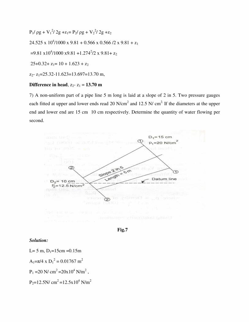
7) A non-uniform part of a pipe line 5 m long is laid at a slope of 2 in 5. Two pressure gauges
each fitted at upper and lower ends read 20 N/cm2 and 12.5 N/ cm2. If the diameters at the upper
end and lower end are 15 cm 10 cm respectively. Determine the quantity of water flowing per
second.
Fig.7
Solution:
L= 5 m, D1=15cm =0.15m
A1=π/4 x D12 = 0.01767 m2
P1 =20 N/ cm2 =20x104 N/m2 ,
P2=12.5N/ cm2 =12.5x10⁴ N/m2

Dia. At the lower end, D2=300mm =0.3m
A2=π/4 x D22 = 0.00785 m2
Let the datum line is passing through the centre of the lower end
Then z2=0
As slope is 2 in 5 hence, z1=2/5 x5= 2 m
Q= A1V1=A2V2
V1 = A2V2/A1 =0.00785x V2 /0.01767
V1 = 0.444 V2
Applying Bernoulli’s eqn. at (1) and (2), we get
P1/ ρg + V12/ 2g +z1 = P2/ ρg + V2
2/ 2g +z2
7.645 + 2 = V22 /2g x 0.8028
V2=15.35 m/s
Discharge, Q= A2V2 = 0.00785 x 15.35 = 0.1205 m3/s
Q = 120.5 lit/s
Problems on Bernoulli’s Eqn. for real fluid:
1) A pipe line carrying oil (specific gravity of 0.8) changes in diameter from 300 mm at
position 1 to 600 mm diameter at poison 2, which is 5m at a higher level. If the pressure at
position 1 and 2 are 100 kN/m2 and 60 kN/m2 respectively and the discharge is 300 lit/sec,
determine,
(a) Loss of head, and
(b) Direction of flow.

Fig.1
Solution:
Discharge Q= 300 lit/sec = 300/1000= 0.3 m3/sec
Specific gravity of oil= 0.8
Weight of oil, Woil = 0.8*9.81= 7.85 kN/m3
At position 1:
Dia of pipe, D1= 300 mm= 0.3 m
Therefore area of pipe, A1= (π/4)*(0.3)2 = 0.0707 m2
Pressure at 1, p1= 100 kN/m3
If the datum line passes through section 1,
Then Z1=0
Velocity, V1= (Q/A1) = (0.3/0.0707)
V1= 4.24 m/sec
At position 2
Dia of pipe, D2= 600 mm= 0.6 m
Therefore area of pipe, A2= (π/4)*(0.6)2 = 0.2828 m2
5 m

Pressure, p2 = 60 kN/m2
Datum, Z2=5m
Velocity, V2= (Q/A2) = (0.3/0.2828)= 1.06 m/sec
(a) Loss of head, hL
Total energy at position 1,
E1= (p1/W) + (V12 /2g) + Z1
E1= (100/7.85) + (4.242/2*9.81)+0
E1 = 12.74+0.92 = 13.66m
Total energy at position 2,
E2= (p2/W) + (V22 /2g) + Z2
E2= (60/7.85) + (1.062/2*9.81) + 5= 7.64+0.06+5
E2= 12.76m
Therefore loss of head,
hL= E1-E2 =13.66-12.76 = 0.9m
(b) Direction of flow
Since E1 >E2, therefore flow taken place from position 1 to position 2
2) A conical tube length 3m is fixed vertically with its small end upwards. The velocity of flow
at the smaller end is 10 m/sec. The pressure head at the smaller end is 4m of liquid. The loss of
head in the fluid in the tube is 0.4(V1-V2)2 /2g, where V1 is the velocity at the smaller end and
V2 at the lower/larger end respectively. Determine the pressure head at lower (larger) end.
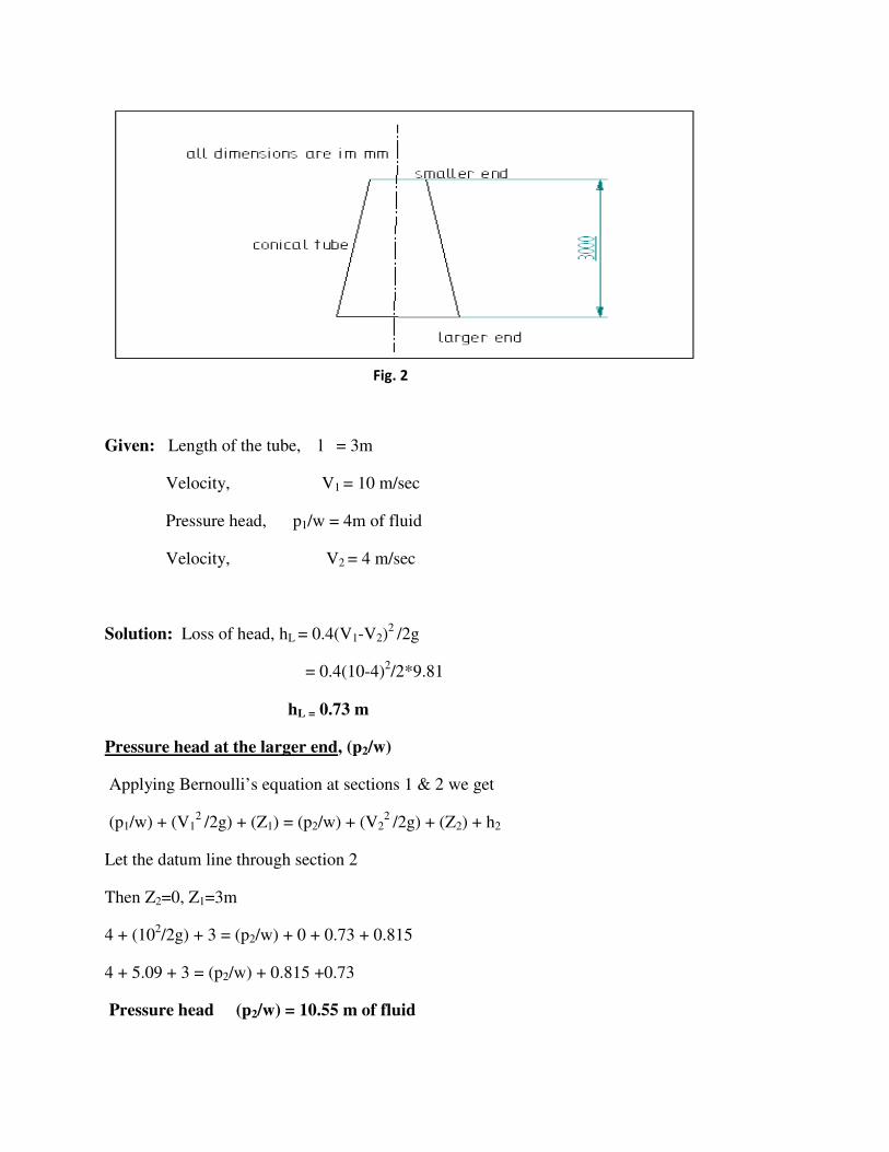
Given: Length of the tube, l = 3m
Velocity, V1 = 10 m/sec
Pressure head, p1/w = 4m of fluid
Velocity, V2 = 4 m/sec
Solution: Loss of head, hL = 0.4(V1-V2)2 /2g
= 0.4(10-4)2/2*9.81
hL = 0.73 m
Pressure head at the larger end, (p2/w)
Applying Bernoulli’s equation at sections 1 & 2 we get
(p1/w) + (V12 /2g) + (Z1) = (p2/w) + (V2
2 /2g) + (Z2) + h2
Let the datum line through section 2
Then Z2=0, Z1=3m
4 + (102/2g) + 3 = (p2/w) + 0 + 0.73 + 0.815
4 + 5.09 + 3 = (p2/w) + 0.815 +0.73
Pressure head (p2/w) = 10.55 m of fluid
Fig. 2

3) A conical tube of length 2 m is fixed vertically with its smaller end upwards. The velocity of
flow at the smaller end is 5 m/s while at the lower end it is 2m/s. the pressure head at the smaller
end is 2.5 m of liquid. The loss of head in the tube is 0.35(v1– v2)2/2g, where V1 is the velocity at
smaller end and V2 at the lower end respectively. Determine the pressure head at the lower end.
Flow takes place in the downward direction.
Solution:
Length of the tube, L=2m
V1= 5 m/s
P1/ ρg = 2.5 m of liquid
V2= 2 m/s
Loss of head = hL= 0.35(v1 – v2)2/2g
=0.35(5 – 2)2/2g = 0.35 x 9/ 2 x9.81
=0.16 m
Pressure head = P2/ ρg
Applying Bernoulli’s equation at (1) and (2) we get
P1/ ρg + V12/ 2g +z1= P2/ ρg + V2
2/ 2g + hL
Fig. 3
Let the datum line passes through section (2). Then
z1= 2, z2=0
2.5+52/2x 9.81+2 = P2/ ρg + 22/ 2 x9.81 +0.16+0
2.5 + 1.27+2= P2/ ρg+ 0.203 +0.16
P2/ ρg = 5.77- 0.363
= 5.047 m of fluid
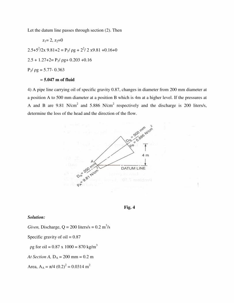
4) A pipe line carrying oil of specific gravity 0.87, changes in diameter from 200 mm diameter at
a position A to 500 mm diameter at a position B which is 4m at a higher level. If the pressures at
A and B are 9.81 N/cm2 and 5.886 N/cm2 respectively and the discharge is 200 liters/s,
determine the loss of the head and the direction of the flow.
Fig. 4
Solution:
Given, Discharge, Q = 200 liters/s = 0.2 m3/s
Specific gravity of oil = 0.87
ρg for oil = 0.87 x 1000 = 870 kg/m3
At Section A, DA = 200 mm = 0.2 m
Area, AA = π/4 (0.2)2 = 0.0314 m2

PA = 9.81 N/cm2 = 9.81 x 10⁴ N/m2 If the Datum line is passing through A, then ZA = 0
VA = Q/AA = 0.2/0.0314 = 6.369 m/s
At section B, DB = 500 mm = 0.5 m
Area, AB = π/4 (0.5)2 = 0.1963 m2
PB = 5.886 N/cm2 = 5.886 x 10⁴ N/m2
ZB = 4 m
VB= Q/ Area = 0.2/0.1963 = 1.018 m/s
Total energy at A, EA = PA/ ρg + VA2/ 2g+zA
= 11.49+2.067+0
= 13.557 m
Total energy at B, EB = PB/ ρg + VB2/ 2g+zB
= 6.896+0.052+4
= 10.948 m
Direction of flow. As EA is more than EB and hence flow is taking place from A to B.
Loss of head = hL = EA – EB = 2.609 m
5) A pump has a tapering pipe running full of water. The pipe is placed vertically with the
diameters at the base and the base and top being 1.2 m and 0.6 m respectively. The pressure at
the upper end is 240 mm of Hg vacuum, while the pressure at the lower end is 15kN/m2. Assume
the head loss to be 20 percent of difference of velocity head. Calculate the discharge, the flow is
vertically upwards and difference of elevation is 3.9 m.

Fig.5
D1=1.2m, D2=0.6m
P1 =15 kN/m2 =15 x 1000 N/m2,
P2/ ρg=240 mm of Hg =0.24 m of Hg
ρm=density of Hg =(13.6 x 1000) kg/m3
Head loss
hL =20/100 of difference of velocity head,
= 0.2(V22 – V1
2) /2g
Difference of vertical height z2- z1=3.9 m
Pressure head at upper end is 240 mm of Hg
Hence P2/ ρmg = -0.24 m of Hg
P2= -0.24 x 13.6 x 1000 x 9.81
= -32019.8 N/m2
Using continuity equation
A1V1=A2V2
V2= A2V2/A2, = (D1 /D2)2 x V1 = 4 V1
Applying Bernoulli’s eqn. at (1) and (2) we get

P1/ ρg + V12/ 2g +z1= P2/ ρg + V2
2/ 2g + hL
V22/2g - V1
2 /2g +3.9 +0.2(V22 -V1
2 /2g
1.529+3.264=1.2(V22 -V1
2)/2g +3.9
4.793 =1.2((4V1)2 -V1
2)/2g +3.9
0.893 =9V12/g
V1= 0.9865 m/s
Discharge Q=A1V1 = 1.1157 m3/s
Practical applications of Bernoulli’s equation:
Although Bernoulli’s equation is applicable in all problems of incompressible flow where
there is involvement of energy considerations. But we shall consider its application to the
following measuring devices.
1) Venturimeter
2) Orifice meter
3) Pitot tube
Differential Pressure Flow Meters
Differential pressure flow meters all infer the flow rate from a pressure drop across a restriction
in the pipe. For many years, they were the only reliable methods available, and they remain
popular despite the development of higher performance modern devices, mostly on account of
exceptionally well researched and documented standards.
The analysis of the flow through a restriction (Fig.1) begins with assuming straight, parallel
stream lines at cross sections 1 and 2, and the absence of energy losses along the streamline from
point 1 to point 2.
Fig. 1: A generalized restriction/differential pressure flow meter
The objective is to measure the mass flow rate, m. By eqn. continuity
m. = ρv1a1 = ρv2a2.
Bernoulli’s equation may now be applied to a streamline down the centre of the pipe from a
point 1 well upstream of the restriction to point 2 in the vena contracta of the jet immediately
downstream of the restriction where the streamlines are parallel and the pressure across the duct
may therefore be taken to be uniform:
Unit 5: Fluid Flow Measurements
Introduction:
Fluid flow measurements means the measuring the rate of flow of a fluid flowing through a pipe
or through an open channel. The rate of flow of a fluid through a pipe is measured by four main
restriction devices are.
� Venturimeter
� Orifice meter
� Pitot tube
� flow nozzle
Whereas through an open channel the rate of flow is measured by
� Notches
� weirs
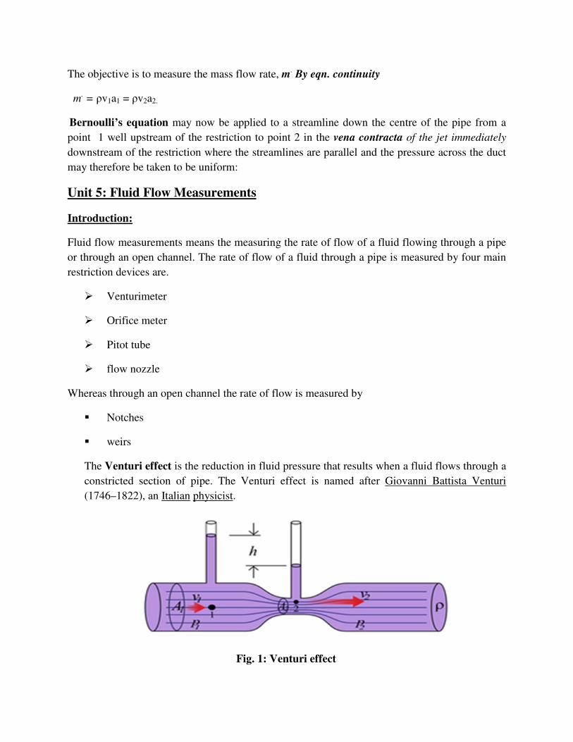
The Venturi effect is the reduction in fluid pressure that results when a fluid flows through a
constricted section of pipe. The Venturi effect is named after Giovanni Battista Venturi
(1746–1822), an Italian physicist.
Fig. 1: Venturi effect

The pressure at "1" is higher than at "2" because the fluid speed at "1" is lower than at "2".The
Venturi effect may be observed or used in the following:
� Inspirators that mix air and flammable gas in grills, gas stoves,
Bunsen burners and airbrushes
� Atomizers that disperse perfume or spray paint (i.e. from a spray gun).
� Carburetors that use the effect to suck gasoline into an engine's intake air stream
� The capillaries of the human circulatory system, where it indicates aortic regurgitation
� Aortic insufficiency is a chronic heart condition that occurs when the aortic valve's initial
large stroke volume is released and the Venturi effect draws the walls together, which
obstructs blood flow, which leads to a Pulsus Bisferiens.
� Cargo Eductors on Oil, Product and Chemical ship tankers
� Protein skimmers (filtration devices for saltwater aquaria)
� Compressed air operated industrial vacuum cleaners
� Venturi scrubbers used to clean flue gas emissions
� Injectors (also called ejectors) used to add chlorine gas to water treatment chlorination
systems
� Sand blasters used to draw fine sand in and mix it with air
� A scuba diving regulator to assist the flow of air once it starts flowing
� In Venturi masks used in medical oxygen therapy
� In recoilless rifles to decrease the recoil of firing
� Wine aerators, to aerate wine, putatively improving the taste.
� Ventilators
� The diffuser on an automobile
The main advantages of the Venturimeter over the orifice plate are:
• Low head loss
• Less affected by upstream flow disturbance
• Good performance at higher β

• Even more robust
• Self-cleaning
• Less affected by erosion
The disadvantages compared to the orifice are
• Occupies longer length of pipe
• More expensive (manufacture and installation)
The simplest apparatus, built out of PVC pipe as shown in the photograph is a tubular setup
known as a Venturi tube or simply a venturi. Fluid flows through a length of pipe of varying
diameter.
Fig. 2: Venturimeter - Experimental apparatus
To avoid undue drag, a Venturi tube typically has an entry cone of 21 to 30 degrees and an exit
cone of 5 to 15 degrees. To account for the assumption of an in viscid fluid a coefficient of
discharge is often introduced, which generally has a value of 0.98. A venturi can be used to
measure the volumetric flow rate Q.

Fig 3 : Venturimeter (Furness 1989)
The fluid velocity must increase through the constriction to satisfy the equation of continuity,
while its pressure must decrease due to conservation of energy: the gain in kinetic energy is
balanced by a drop in pressure or a pressure gradient force. An equation for the drop in pressure
due to the Venturi effect may be derived from a combination of Bernoulli's principle and the
equation of continuity.
Expression for rate of flow through venturimeter :
Consider a venturimeter fixed in a horizontal pipe through
which a fluid is flowing (say water) as shown in figure 4.
Let d1 = diameter at inlet or at section 1
p1 =Pressure at section 1
v1 = velocity of fluid at section 1
a1 = area at section 1= (π/4)*d12
And d2, p2, v2, a2 are corresponding values at section 2
Applying Bernoulli’s equation at section 1 & 2 we get
(p1/ρg) + (v12 /2g) + (z1) = (p2/ρg) + (v2
2 /2g) + (z2)

Fig. 4 Typical venturimeter
As pipe is horizontal, hence z1=z2
(p1/ρg) + (v12 /2g) = (p2/ρg) + (v2
2 /2g) or
(p1-p2)/ρg = (v22 /2g) - (v1
2 /2g) ---- (1)
But (p1-p2)/ρg, is the difference of pressure head at sections 1 & 2 and it is equal to ‘h’ or
(p1-p2)/ρg = h
Substituting the value of (p1-p2)/ρg in the above eqn. (1) we
Get, h = (v22 /2g) - (v1
2 /2g) ---- (2)
now applying continuous equation at sections 1 & 2
a1v1= a2v2 or v1 = (a2v2)/ a1
substitute the value of v1 in equation (2)
h= (v22 /2g) - [(a2v2/ a1)
2 /2g] = (v22 /2g)[1-(a2
2/a12)]
= (v22 /2g)[(a1
2- a22)/ a1
2]
v22 =2gh [a1
2 /( a12- a2
2)]

Therefore v2 =√[2gh {a12 /( a1
2- a22)}]
v2 = [a1 /√( a12- a2
2)]* √(2gh)
Discharge Q = a2v2
Qth = a2*[a1 /√( a12- a2
2)]* √(2gh) ---- (3)
Equation (3) gives the discharge under ideal conditions and is called theoretical discharge.
Actual discharge will be less than theoretical discharge.
Qact = Cd[a1a2 /√( a12- a2
2)]*√(2gh)]
Where Cd is coefficient of venturimeter and its value is less than 1.
Value of ‘h’ by differential ‘U’ tube manometer
Case 1:
Let the differential manometer contains a liquid which is heavier than the liquid flowing
through a pipe.
Let
sh=specific gravity of the heavier liquid.
sp=specific gravity of the liquid flowing through pipe.
x=difference of the heavier liquid column in U-tube.
h=x[(sh/sp) -1]
Case 2:
If the differential manometer contains a liquid which is lighter than the liquid flowing
through the pipe, the value of ‘h’ is given by
h= x[1-(sL/sp)]
Where
sL=sp gravity of lighter liquid in U-tube.
sp=sp gravity of the liquid flowing through pipe
x= difference of the lighter liquid column in U-tube.

Case 3:
Inclined venturimeter with differential U-tube manometer (heavier liquid)
h= (p1/ρg+z1) - (p2/ρg + z2) = x[(sh/sp)-1]
Case 4:
Inclined venturimeter with differential U-tube manometer(lighter liquid)
h= (p1/ρg+z1) - (p2/ρg + z2) = x[1-(sL/sp)]
Problems on Horizontal Venturimeter:
1) A horizontal venturimeter with inlet and throat diameters 30cm and 15cm respectively is used
to measure the flow of water. The reading of differential manometer connected to the throat and
inlet is 20cm of mercury. Determine the rate of flow. Take Cd=0.98.
Solution:
Given:
Dia at inlet, d1 =30cm, Area at inlet, a1= (πd12)/4
= (π302)/4 =706.85cm2
Dia at throat, d2 =15cm, Area at throat, a2 = (π152)/4 =176.7cm2
Cd =0.98
Reading of differential manometer x = 20cm of mercury
Therefore difference of pressure head is given by
h =x [(sh/sw)-1]
Where sh=specific gravity of mercury =13.6,
sw=specific gravity of water(assumed) =1
h =20[(13.6/1)-1] =20*12.6cm =252.0 cm of water.
The discharge through venturimeter is given by
Q = Cd*(a1a2/(√a12-a2
2))*(√2gh)
= 0.98*(706.85*176.7/(√706.852176.72))*(√2*9.81*25)
= 86067593.36/(√499636.9-31222.9)

= 86067593.36/684.4
= 125756cm3/s=125756lit/s
Q = 125.756 lit./s
2) An oil of specific gravity 0.8 is flowing through a venturimeter having inlet diameter 20cm
and throat diameter 10cm. The oil(so = 0.8)-mercury differential manometer shows a reading of
25cm. Calculate the discharge of oil through the horizontal venturimeter. Take Cd=0.98.
Solution:
Given:
Specific gravity of oil, so =0.8
Specific gravity of mercury sh =13.6
Reading of differential manometer x =25cm
Therefore difference of pressure head, h =x [(sh/so) -1]
=25[(13.6/0.8) -1] cm of oil = 25[17-1] =400 cm of oil.
Dia at inlet, d1=20cm
Area at inlet, a1 = (πd12)/4 = (π202)/4 =314.16cm2
Similarly at throat, d2 =10cm
a2 =(π102)/4 =78.54cm2
Cd = 0.98 (given)
Therefore discharge Q is given by
Q = Cd*(a1a2/(√a12-a2
2))*(√2gh)
=0.98*(314.16*78.54/(√314.162-78.542))*(√2*9.81*400)
=21421375.68/ (√98696-6168)
=21421375.68/304 cm3/s
=70465cm3/s
Q =70.465 lit/s
3) A venturimeter is to be fitted in a pipe of 0.25 m dia. where the pressure head is 7.6 m of
flowing liquid and max. flow is 8.1 m3/min. Find the least dia. of the throat to ensure that the
pressure head does not become negative, cd = 0.96.
Solution:
Q= cd((a1a2)/(√a12-a2
2))*√(2gh)
Q = (8.1/60) = 0.135 m3/s, cd = 0.96
a1 = (π/4)*(0.25)2 = 0.049 m2
h = 7.6 m
0.135 = 0.96*((0.049*a2)/(√0.0492-a22))*√(2*9.81*7.6)
a2 = 0.0112 m2
4) A venturimeter is used for measurement of discharge of water in a horizontal pipe line, if the
ratio of upstream pipe diameter to that of throat is 2:1, upstream diameter is 300mm, the
difference of pressure between the throat is equal to 3m head of water and loss of head through
meter is one eighth of the throat velocity head, calculate discharge in pipe
Solution:
Given:
Ratio of inlet dia to throat i.e., d1/d2=2
d1=300mm=0.3m
d2=300/2=150mm=0.15m
(p1/ρg - p2/ρg)=3m of water ,
loss of head, hf=1/8 of throat velocity head =1/8*v22/2g
Using continuity equation
Using Bernoulli's equation at inlet and throat, we get

5) A horizontal venturimeter with inlet diameter 200mm and throat diameter 100mm is
employed to measure the flow of water. The reading of the differential manometer connected to
the inlet is 180mm of Hg. If the coefficient of discharge is 0.98, determine the rate of flow.
Solution:
Inlet dia of venturimeter, D1= 200mm= 0.2m
Therefore, area of inlet, A1= (π/4)*0.22
Throat dia D2= 100mm= 0.1m
Area of throat, A2= (π/4)*0.12
Reading of differential manometer, x = 180mm
= 0.18m of Hg
Coefficient of discharge, Cd =0.98

Rate of flow, Q
To find the difference of pressure head (h), we have
h = x[(sh/sp)-1]
h = 0.18[(13.6/1) -1]= 2.268 m
To find ‘Q’ using this relation
Q = Cd[a1a2 /√( a12- a2
2)]* √(2gh)
Q = 0.98[0.0314*0.00785 /√( 0.03142-0.007852)]* √(2*9.81*2.268)
Q= (0.000241*6.67)/0.0304
Q = 0.0528 m3/sec
6) A venturimeter having a diameter of 75mm at throat and 150mm dia at the enlarged end is
installed in a horizontal pipeline 150mm in dia carrying an oil of specific gravity 0.9. The
difference of pressure head between the enlarged end and the throat recorded by a U-tube is
175mm of mercury. Determine the discharge through the pipe. Assume the coefficient of
discharge of the water as 0.97.
Solution:
The discharge through the venturimeter is given by
Q = Cd[a1a2 /√( a12- a2
2)]* √(2gh)
Cd =0.97
d1 =150mm= 0.15m
a1 =(π/4)*0.152 = 0.0177m2
d2 =75mm= 0.075m
a2 = (π/4)*0.0752 = 0.0044m2
x= 175mm = 0.175m
h =x[(sh/sp) -1] = 0.175[(13.6/0.9)-1]
= 2.469m
by substitution, we get

Q=0.97[0.0177*0.0044 /√( 0.01772- 0.00442)]*√(2*9.81*2.469)
Q= 0.03067 m3/sec
= 30.67 lit/sec
7) A horizontal venturimeter with inlet diameter 20cm and throat dia 10cm is used to measure
the flow of oil of specific gravity 0.8. The discharge of the oil through venturimeter is 60 lit/sec.
Find the reading of the oil-Hg differential manometer, take Cd= 0.98.
Solution:
At entry, d1=20cm
a1= (π/4)*202 = 314.16 cm2
At throat, d2 = 10cm
a2 = (π/4)*102 = 78.54 cm2
Cd = 0.98
Q = 60 lit/sec= 60*1000 cm3/sec
Q = Cd[a1a2 /√( a12- a2
2)]* √(2gh)
60*1000 = 0.98[314.16*78.54/√( 314.162-78.542)]*√(2*9.81*h)
√h= 17.029, h= 289.98 cm of oil
To calculate reading of the oil-Hg differential manometer
we have
h =x[(sh/sp)-1]
Where sh = 13.6 –> sp. gravity of the mercury
sp = 0.8 --> sp. gravity of the oil
x = ?
x= 18.12 cm

8) A horizontal venturimeter with inlet*throat diameter 300mm and 100mm respectively is used
to measure the flow of water. The pressure intensity at inlet is 130 kN/m2, while the vacuum
pressure head at the throat is 350mm of Hg. Assume that 3% of head is lost in between the inlet
and throat, find
1) The value of Cd for the venturimeter
2) Rate of flow.
Solution:
Inlet dia of the venturimeter, D1 = 300mm = 0.3m
Area of inlet, A1 = (π/4)*0.32 = 0.07m2
Throat dia, D2 = 100mm= 0.1m
Area of throat, A2 = (π/4)*0.12 =0.00785m2
Pressure at inlet, p1 =130KN/m2
Pressure head, p1/w=130/9.81= 13.25m
Similarly, pressure head at throat
p2/w = - 350mm of Hg(vacuum pr. Head)
= - 0.35*13.6
= - 4.76 m of water
(a) coefficient of discharge, Cd
Differential head, h = (p1/w) - ( p2/w) = 13.25 -(- 4.76)
h = 18.01m
head lost, hf = 3% of h= (3/100)*18.01 = 0.54m
Cd =√[(h- hf)/h]= √[(18.01-0.54)/18.01] = 0.985
(b)Rate of flow, Q
Q = Cd[a1a2 /√( a12- a2
2)]* √(2gh)
Q = 0.985[0.07*0.00785 /√( 0.072- 0007852)]*√(2*9.81*18.01)
Q= 0.146 m3/sec
9) The inlet and throat diameter of a horizontal venturimeter are 30cm and 10cm respectively.
The liquid flowing through the meter is water. The pressure intensity at inlet is 13.734N/cm3
while the vacuum pressure head at the throat is 37cm of mercury. Find the rate of flow. Assume
that 4% of the differential head is lost between the inlet and throat. Find also the value of Cd for
the venturimeter.
Solution:
Given:
Dia at inlet, d1=30cm
Area at inlet, a1=(πd12)/4=(π302)/4=706.85cm2
Dia at throat, d2=10cm
Area at throat, a2=(π102)/4=78.54cm2
Pressure at entry, p1=13.734N/cm2=13.734*104N/m2
Therefore pressure head, p1/ρg=13.734*104/9.81*1000
=14m of water
p2/ρg= -37cm of mercury
= (-37*13.6/100) m of water
=-5.032 m of water
Differential head, h = p1/ρg- p2/ρg=14-(-5.032) =14+5.032
= 19.032 m of water
=1903.2 cm
Head lost, hf= 4% of h=0.04*19.032=0.7613 m
Cd=√((h- hf)/h) =√(19.032-0.7613)/19.032
=0.98
Therefore discharge
Q= Cd*(a1a2/(√a12-a2
2))*(√2gh)
= 0.98*(706.85*78.54/(√706.852 - 78.542))*(√2*9.81*1903.2)

= (105132247.8)/√(499636.9-6168)=149692.8cm3/s
Q = 0.14969m3/s
10) A horizontal venturimeter with inlet diameter 20cm and throat diameter 10cm is used to
measure the flow of water. The pressure at inlet is 17.658 N/cm2 and the vacuum pressure at the
throat is 30cm of mercury. Find the discharge of water through venturimeter. Take Cd=0.98
Solution:
Dia at inlet, d1=20cm
a1=(πd12)/4=(π202)/4=314.16cm2
Dia at throat,d2=10cm
a2=(π102)/4=78.54cm2
p1=17.658 N/cm2=17.658*104N/m2
density of water = 1000kg/m3 and
Therefore, p1/ρg=17.658*104/9.81*1000=18m of water
p2/ρg= -30cm of mercury (vacuum pr. Head)
= - 0.30m of mercury
= - 0.30*13.6
= - 4.08 m of water
Therefore differential head
h= p1/ρg - p2/ρg =18-(-4.08)
= 18+4.08=22.08 m of water
= 2208 cm of water
The discharge Q is given by equation
Q= Cd*(a1a2/(√a12-a2
2))*(√2gh)
=0.98*(314.16*78.54/(√314.16278.542))*(√2*9.81*2208)
=50328837.21/304

=1655555 cm3/s
Q =165.55 lit/s
Problems on venturimeter axis vertical/inclined
1) A venturimeter has its axis vertical , the inlet & throat diameter being 150mm & 75mm
respectively. The throat is 225mm above inlet and Cd = 0.96. Petrol of specific gravity 0.78 flows
up through the meter at a rate of 0.029 m3 /sec. find the pressure difference between the inlet and
throat.
Solution:
Fig. 1: venturimeter with its axis vertical
The discharge through a venturimeter is given by
Q = Cd [a1a2 /√( a12- a2
2)]* √(2gh)
Given:
Cd = 0.96
d1 =150mm= 0.015m
d2 =75mm= 0.0075m
a1 =(π/4)*0.0152 =0.0177m2
a2 =(π/4)*0.00752 =0.0044m2
Q = 0.029 m3/sec
By substitution, we have

0.029 = 0.96[0.0177*0.0044 /√( 0.01772- 0.00442)]*√(2*9.81*h)
h= 2.254m of oil
h= (p1/w+z1) - (p2/w + z2)
2.254= [(p1/w)- (p2/w)]-[ z2-z1]
2.254= [(p1/w)- (p2/w)]-[0.225]
p1/ρg - p2/ρg =2.479
Therefore, p1 - p2= 2.479*0.78*9810
= 18969 N/m2 =18.969k N/m2 =18969 Pa
Pr. Difference, p1 - p2 = 18.96 kPa
2)Determine the rate of flow of water through a pipe of 300mm dia placed in an inclined position
where a venturimeter is inserted, having a throat dia of 150mm.The difference of pressure
between the main throat is measured by a liquid of specific gravity 0.7 in an inverted u-tube
which gives a reading of 260mm.The loss of head the main and throat is 0.3 times the kinetic
head of the pipe.
Solution:
Fig. 2
Given:
Dia of inlet,
D1=300mm=0.3m
Therefore area of inlet, A1= π/4*(0.3)2=0.07m2

Throat dia, D2=150mm=0.15m
Therefore area of throat, A2= π/4*(0.15)2=0.01767m2
Specific gravity of lighter liquid (u-tube) sl =0.7
Specific gravity of liquid (water) flowing through pipe,
Reading of differential manometer, x=260mm=0.26m
Difference of pressure head, h is given by
((p1/ρg) +z1) - (p2/ρg) +z2) =h
Also, h= x (1- sl/sw) =0.26(1-0.7/1.0)
=0.078m of H2O
Loss of head, hL=0.3*kinetic head of pipe = 0.3 * v12/2g
Now applying Bernoulli’s equation at section ‘1’ and ‘2’,
We get, (p1/ρg) + z1 + (v12/2g) = (p2/ρg) +z2 + (v2
2/2g ) + hL
[(p1/ρg) +z1) - (p2/ρg) +z2 ]+ [(v12/2g) - (v2
2/2g)] = hL
But [(p1/ρg) +z1) - (p2/ρg) +z2 ] =0.078 m of H2O
And hL =0.3*(v12/2g)
therefore, 0.078 + [(v12/2g) - (v2
2/2g)] = 0.3*(v12/2g)
0.078 +0.7(v12/2g) - (v2
2/2g) = 0 ---- (1)
Applying continuity equation on section (1) and (2) ,
we get A1v1=A2v2
v1= A2v2/A1 = v2/4
Substitute ‘v1’ in equation (1), we get
0.078 + (0.7(v22/4))/2g - (v2
2/2g) = 0
0.078 + (v22/2g) ((0.7/16)-1) = 0
(v22/2g) * (-0.956) = - 0.078
v22=0.078*2*9.81/0.956=1.6

v2 =1.26m/s
Rate of flow Q= A2v2=0.01767*1.26
Q=0.0222m3/s
3) 215 litres of gasoline (specific gravity 0.82) flow per second through an inclined venturimeter
fitted to a 300 mm dia pipe. The venturimeter is inclined at an angle of 600 to the vertical and its
150 mm dia. throat is 1.2 m from the entrance along its length. Pressure at throat =0.077 N/mm2,
calculate Cd.
If instead of pressure gauges the entrance and throat of the venturimeter are connected to the
two limbs of a U=tube manometer. Determine its reading in mm of differential mercury column.
Solution:
Discharge, Q=Cd((a1a2)/(√a12-a2
2))*√(2gh) = 215*10-3 = 0.215 m3/s
a1 = (π/4)*(300/1000)2 = 0.0707 m2
a2 = (π/4)*(150/1000)2 = 0.0177 m2
h = ((p1/w) +z1) - ((p2/w) +z2)
p1/w = (0.141 *106)/(9810*0.82) = 17.528 m of gasoline
p2/w = (0.077 *106)/(9810*0.82) = 9.572 m of gasoline
z1 = 0, z2 = (1.2 sin 30) = 0.66m
h = (17.528 + 0) – (9.572 + 0.66) = 7.356 m
0.215 = Cd((0.0707*0.0177)/(√0.07072-0.01772))*√(2*9.81*7.356)
Cd = 0.979
When a U-tube manometer is connected,
h = x((sm/so)-1)
7.356 = x((13.6/0.82)-1)
x = 0.472 m
x = 472 mm

4) The following data relate to an inclined venturimeter:
Diameter of the pipe line = 400 mm
Inclination of the pipe line with the horizontal =300
Throat diameter = 200 mm
The distance between the mouth and throat of the meter = 600 mm
Specific gravity of the oil flowing through the pipe line = 0.7
Specific gravity of the heavy liquid (U-tube) = 13.6
Reading of the differential manometer =50 mm
The co-efficient of the meter = 0.98
Determine the rate of flow in the pipe line.
Fig. 4
Difference of pressure head h is given by :
h = x[(sh/sp)-1]
where shl = specific gravity of heavy liquid (i.e. mercury) in U-tube = 13.6
sp = specific gravity of liquid (i.e. oil) flowing (sp. gr. = 0.7) trough the pipe = 0.7
Therefore h = 0.05[(13.6/0.7)-1] = 0.92 m of oil
Now applying Bernoulli’s equation at section ‘1’ and ‘2’, we get,

(p1/w) + (v12/2g) + z1 = (p2/w) + (v2
2/2g) + z2 ……. (i)
((p1/w) + z1)) – ((p2/w) + z2)) + (v12/2g) - (v2
2/2g) = 0
((p1/w) + z1)) – ((p2/w) + z2) = h
(p1/w) - (p2/w) + (z1 - z2) = h
It may be noted that differential gauge reading will include in itself the difference of pressure
head and the difference of datum head
Thus equation (i) reduces to :
h + (v12/2g) - (v2
2/2g) = 0 …… (ii)
applying continuity equation at section ‘1’ and ‘2’ we get, A1V1 = A2V2
or V1 = (A2V2)/ A1
=(0.0314* V2)/0.1257
= V2/4
Substituting the value of V1 and h in eq. (ii) we get,
0.92 + (v22/16*2g) - (v2
2/2g) = 0
(v22/2g) (1-(1/16)) = 0.92 or v2
2* (15/16)
= 0.92
or v22 = (0.92*2*9.81*16)/15
= 19.52
or v2 = 4.38 m
rate of flow of oil, Q = A2V2 = 0.0314*4.38
Q = 0.1375 m3/s
5) A vertical venturimeter has an area ratio 5. It has a throat diameter of 10 cm. when oil of
specific gravity 0.8, flows through it the mercury in the differential gauge indicates a difference
in height of 12 cm. Find the discharge through the venturimeter. Take Cd=0.98.

Solution:
Area ratio, k=a1/a2=5,
throat diameter, d2=10cm=0.1m and area a2=π/4*0.122
Specific gravity of oil, s0=0.8,
difference of Hg level, x=12cm=0.12m
Now differential head (ii) is given by,
The discharge is given by,
The discharge can be expressed in terms of area, Ratio (k) as
Q= Cd ((a1a2)/(√(a12-a2
2))*√(2gh)
= Cd ((a1/a2)*a2)/(√((a12/a2
2)-a22/a2
2))*√(2gh)
= Cd ((k*a2)/(√k2-1))*√(2gh)
= 0.98*((5*π(0.1)2/4)/(√(5)2-1))*√(2*9.81*1.92)
Q = 0.0482 m3/s
6) In a vertical pipe conveying oil of specific gravity 0.8, two pressure gauges have been
installed at A and B where the diameters are 16cm and 18cm respectively. A is 2 meters above
B. The pressure gauge readings have shown that the pressure at B is greater than at A by
0.981N/cm2. Neglecting all losses, calculate the flow rate. If the gauges at A and B is replaced by
tubes filled with same liquid and connected to a U-tube containing mercury, calculate the
difference of level of mercury in the two limbs of the U-tube.

Solution:
Specific gravity of oil s0=0.8
Density, ρ =0.8*1000=800kg/m3
Dia at A DA=16cm =0.16m
area at A, A1 =0.02 m2
Dia at B, DB =18cm =0.18m
area at B,
i)Difference of pressure,
pB - pA= 0.981 N/m2= 9810 N/m2
Difference of pressure head
pB-pA=9810/(800*9.81) = 1.25
Applying Bernoulli’s theorem at A and B, we get
Now applying continuity equation at A and B, we get
VA*A1=VB*A2
Substituting the value of VB , we get

Difference level of mercury in the U-tube
Let h=Difference of mercury level
Then
7)Estimate the discharge of kerosene (sp gravity=0.8) through the given venturimeter shown in
Fig. 5. specific gravity of mercury(Hg) is 13.55.
Fig. 5
Solution:
Applying Bernoulli’s equation to section 1 and 2
(p1/γ) + (v12/2g) = (p2/γ) + (v2
2/2g) + ∆z
or (p1/γ) – ((p2/γ) + ∆z) = (v22/2g) - (v1
2/2g)
Hence ((p1/γ)- (p2/γ) + ∆z) = 15 v12/2g
Equating the pressures at section AA in the two limbs of the manometer
(p1/γ) + (x + 0.3) = ((p2/γ) + 0.4) + x + (0.3 *(13.85/0.8))
(p1/γ) - (p2/γ) + 0.4) = 5.19 – 0.30 = 4.78 m
15 v12/2g = 5.29 or v1 = 2.63 m/s
Hence Q = 0.785*0.01*2.5 = 0.0196 m3/s = 19.6 l/s
Orifice meter or orifice plate
Orifice Flow Measurement – History:
� The first record of the use of orifices for the measurement of fluids was by Giovanni B.
Venturi, an Italian Physicist, who in 1797 did some work that led to the development of
the modern Venturi Meter by Clemons Herschel in 1886.
� It has been reported that an orifice meter, designed by Professor Robinson of Ohio State
University was used to measure gas near Columbus, Ohio, about 1890.
� About 1903 Mr. T.B. Weymouth began a series of tests in Pennsylvania leading to the
publication of coefficients for orifice meters with flange taps.
� At the same time Mr. E.O. Hickstein made a similar series of tests at Joplin, Missouri,
from which he developed data for orifice meters with pipe taps.
� A great deal of research and experimental work was conducted by the American Gas
Association and the American Society of Mechanical Engineers between 1924 and 1935
in developing orifice meter coefficients and standards of construction for orifice meters

Fig. 1: Tapping arrangements
Fig. 2: Orifice profile
Fig. 3 Typical orifice flow pattern-Flanj taps shown

An orifice in a pipeline is shown in figure 3 with a manometer for measuring the drop in pressure
(differential) as the fluid passes thru the orifice. The minimum cross sectional area of the jet is
known as the “vena contracta.”
What is an Orifice Meter?
� An orifice meter is a conduit and a restriction to create a pressure drop. An hour glass is a
form of orifice.
� A nozzle, venturi or thin sharp edged orifice can be used as the flow restriction. In order
to use any of these devices for measurement it is necessary to empirically calibrate them.
That is, pass a known volume through the meter and note the reading in order to provide
a standard for measuring other quantities.
� Due to the ease of duplicating and the simple construction, the thin sharp edged orifice
has been adopted as a standard and extensive calibration work has been done so that it is
widely accepted as a standard means of measuring fluids.
� Provided the standard mechanics of construction are followed no further calibration is
required.
Major Advantages of Orifice Meter Measurement
� Flow can be accurately determined without the need for actual fluid flow calibration. Well
established procedures convert the differential pressure into flow rate, using empirically
derived coefficients.
� These coefficients are based on accurately measurable dimensions of the orifice plate and
pipe diameters as defined in standards, combined with easily measurable characteristics of
the fluid, rather than on fluid flow calibrations.
� With the exception of the orifice meter, almost all flow meters require a fluid flow
calibration at flow and temperature conditions closely approximating service operation in
order to establish accuracy.
� In addition to not requiring direct fluid flow calibration, orifice meters are simple, rugged,
widely accepted, reliable and relatively inexpensive and no moving parts.
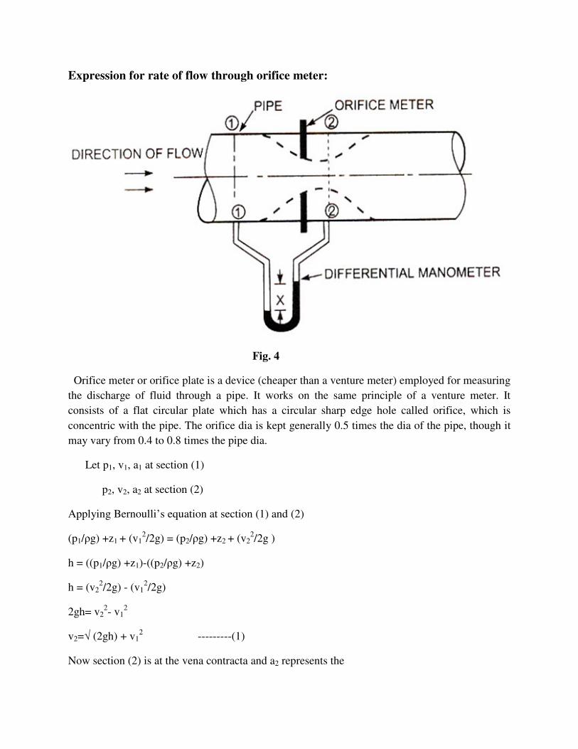
Expression for rate of flow through orifice meter:
Fig. 4
Orifice meter or orifice plate is a device (cheaper than a venture meter) employed for measuring
the discharge of fluid through a pipe. It works on the same principle of a venture meter. It
consists of a flat circular plate which has a circular sharp edge hole called orifice, which is
concentric with the pipe. The orifice dia is kept generally 0.5 times the dia of the pipe, though it
may vary from 0.4 to 0.8 times the pipe dia.
Let p1, v1, a1 at section (1)
p2, v2, a2 at section (2)
Applying Bernoulli’s equation at section (1) and (2)
(p1/ρg) +z1 + (v12/2g) = (p2/ρg) +z2 + (v2
2/2g )
h = ((p1/ρg) +z1)-((p2/ρg) +z2)
h = (v22/2g) - (v1
2/2g)
2gh= v22- v1
2
v2=√ (2gh) + v12 ---------(1)
Now section (2) is at the vena contracta and a2 represents the

area at the vena contracta, if a0 is the area of the orifice,
we have, Cc= a2/a0
where Cc=coefficient of contraction
a2= Cc a0 --------(2)
by continuity equation, we have
v1a1= v2a2
v1= a2/a1*v2 = Cc a0 /a1 * v2 [as a2= Cc a0 ] -------(3)
Substitute the value of v1 in eqn.(1)
v2 =√ (2gh) + (Cc a0 /a1 * v2)2
v22= (2gh) + (a0/a1)
2 Cc2 v2
2
v2=√ (2gh)/ √1-(a0/a1)2 Cc
2
Or h = (v22/2g) - (v1
2/2g) => 2gh = (v22 - v1
2)
2gh= v22 –(Cc a0 /a1 * v2)
2
= v22[1–Cc
2 (a0 /a1 )2]
v2=√ (2gh)/ √1-(a0/a1)2 Cc
2 ……3a
Discharge, Q= v2a2= v2 Cc a0 (since a2= Cc a0)
Substitute for V2
Q = Cc a0 √ (2gh)/ √1-(a0/a1)2 Cc
2 -------(4)
Qth = a0 a1√ (2gh)/ √ ( a12- a0
2)
Qact= Cd a0 a1√ (2gh)/ √ ( a12- a0
2)
Where, Cd=coefficient of discharge of orifice meter. The coefficient of discharge for orifice
meter is much smaller than for a venture meter.

Problems on orifice meter:
1)The following data refers to an orifice meter
Dia of the pipe= 240mm
Dia of the orifice=120mm
Specific gravity of oil=0.88
Reading of differential manometer
x = 400 mm of Hg
Coefficient of discharge of the meter,Cd= 0.65
Determine the rate of flow, Q, of oil
Solution:
Dia of the pipe D1=240mm= 0.24m, A1=0.0452m2
Dia of the orifice D0=120mm= 0.12m,A2=0.0113 m2
Coefficient of discharge, Cd= 0.65
Specific gravity of oil, s0= 0.88
Reading of differential manometer, hg=400mm of Hg = 0.4 m 0f Hg
Therefore differential head, h=x [(sh/ s0)-1]
=0.4[(13.6/0.88)-1]= 5.78 m of oil
Discharge, Q=Cd a0 a1√ (2gh)/ √ (a12- a0
2)
Q = 0.65*0.0113*0.0452*√(2*9.81*5.78)/√(0.04522- 0.01132)
=0.08 m3/s
2) An orifice meter with orifice diameter 10 cm is inserted in a pipe of 20 cm diameter. The
pressure gauges fitted upstream and downstream of the orifice meter give reading of 19.26
N/cm2 and 9.81N/cm2 respectively. Co-efficient of discharge for the meter is given as 0.6. Find
the discharge of water through pipe.

Solution.
Given:
Dia. Of orifice. d0 =10 cm
Therefore area, a0 = (π102)/4 =78.54 cm2
Dia. Of pipe, d1=20 cm
Therefore area, a0 = (π202)/4=314.16 cm2
p1= 19.62 N/cm2 =19.62*104N/m2
(p1/ρg)=(19.62*104)/(1000*9.81)
=20 m of water
Similarly (p2/ρg)=(9.81*104)/(1000*9.81)
=10 m of water
Therefore h=(p1/ρg)-(p2/ρg)= 20.0-10.0
=10.0 m of water=1000 cm of water
Cd=0.6
The discharge, Q is given by
Q=Cd*(a0a1/√a12-a0
2)*√2gh
=0.6*(78.54*314.16/√314.162-78.542)*√2*981*1000
=68213.28 cm3/s
=68.21 lit./s
3) An orifice meter with orifice diameter 15 cm is inserted in a pipe of 30 cm diameter, the
pressure difference measured by a mercury oil differential manometer on the two sides of the
orifice meter gives a reading of 50 cm mercury. Find the rate of oil of specific gravity 0.9 when
the co-efficient of discharge of the meter = 0.64.

Solution:
Given:
Dia. of orifice, d0 = 15 cm
Therefore Area, a0=(π152)/4 =176.7cm2
Dia. of pipe, d1 = 30 cm
Therefore Area, a1=(π302)/4 =706.85cm2
Specific gravity of oil, S0 = 0.9
Reading of diff. manometer, x= 50 cm of mercury
Differential head, h= x(sh/s0-1)=50(13.6/0.9-1)
= 50*14.11=705.5 cm of oil
Co-efficient of discharge,Cd = 0.64
Therefore the rate of the flow, Q is given by
Q = Cd*(a0a1/√a12-a0
2)*√2gh
=0.64*(176.7*706.85/√706.852-176.72)*√2*981*1000
=137414.25 cm3/s
= 137.414 lit./s
Pitot tube
Fig. 1

H= depth of tube in liquid
h=rise of liquid in the tube above the free surface
The Pitot tube (named after the French scientist Pitot) is one of the simplest and most useful
instruments ever devised. the tube is a small glass tube bent at right angles and is placed in flow
such that lower end, which is bent through 900 is directed in the upstream direction as shown
in figure. The liquid rises in the tube due to conversion of kinetic energy into potential energy.
The velocity is determined by measuring the rise of liquid in the tube.
Consider two points (1) & (2) at the same level in such a way that the point (2) is just at the
inlet of the pitot tube and point (1) is far away from the tube
Let p1, v1 & p2, v2 are pressure and velocities at point (1) & (2) respectively
H= depth of tube in liquid
h=rise of liquid in the tube above the free surface
Applying Bernoulli’s equation at point (1) & (2) we get
(p1/ρg) +z1 + (v12/2g) = (p2/ρg) +z2 + (v2
2/2g)
But z1= z2 as point 1 & are on the same line and v2=0
p1/ρg= pressure head at (1) =H
p2/ρg = pressure head at (2) =h+H
Substituting these values, we get
H+ v12/2g= h+H
h= v12/2g
or
v1=√2gh (theoretical velocity)
Therefore the actual velocity ( v1 ) act = Cv√2gh)
Cv =coefficient of pitot tube

Fig.2: Types of pitot tubes
Stagnation pressure and dynamic pressure
Bernoulli's equation leads to some interesting conclusions regarding the variation of pressure
along a streamline. Consider a steady flow impinging on a perpendicular plate (figure 3).
Fig.3: Stagnation point flow.

There is one streamline that divides the flow in half: above this streamline all the flow goes over
the plate, and below this streamline all the flow goes under the plate. Along this dividing
streamline, the fluid moves towards the plate. Since the flow cannot pass through the plate, the
fluid must come to rest at the point where it meets the plate. In other words, it ``stagnates.'' The
fluid along the dividing, or ``stagnation streamline'' slows down and eventually comes to rest
without deflection at the stagnation point.
Bernoulli's equation along the stagnation streamline gives
where the point e is for upstream and point 0 is at the stagnation point. Since the velocity at the
stagnation point is zero,
Pitot-Static Tubes
The devices for measuring flow velocity directly is the Pitot-static tube. Figure 4 shows the
principle of operation
Fig.4: Principle of Pitot-Static tube
By applying Bernoulli’s equation to a streamline which meets the tip of the tube. The flow is
steady, so there is no flow in the tube. Thus there is a stagnation point, so u2 = 0. The pressure
difference p2 - p1 is the difference between the impact or stagnation pressure at the tip of the
tube, p2 , and the static pressure in the body of the fluid, p1 . From Bernoulli,

Fig.5- Pitot-Static tube; detail
The most common practical design based upon the above is shown in Figure 5. A pair of
concentric tubes is used: the inner tube measured the impact pressure, the outer tube has a
number of tiny tappings, flush with the tube, to measure the static pressure. Accuracy is crude,
but these devices do provide a very simple and fast estimate of flow velocity.
They are clearly not well suited to dirty flows in which their tappings may become blocked.
Problems on Pitot tube:
1) A pitot-static tube placed in the centre of a 300 mm pipe line has one orifice pointing
upstream and other perpendicular to it. The mean velocity in the pipe is 0.80 of the central
velocity. Find the discharge through the pipe if the pressure difference between the two orifices
is 60 mm of water. Take the co-efficient of Pitot tube as Cv = 0.98.
Solution.
Given:
Dia. of pipe, d = 30 mm = 0.30 m
Diff. of pressure head, h = 60 mm of water
= 0.06 m of water
coefficient of pitot tube,Cv = 0.98
Mean velocity, V = 0.80* central velocity
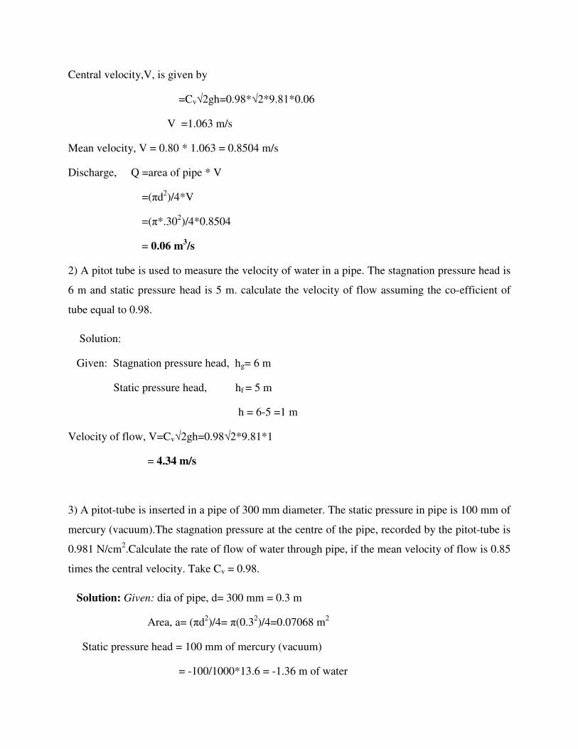
Central velocity,V, is given by
=Cv√2gh=0.98*√2*9.81*0.06
V =1.063 m/s
Mean velocity, V = 0.80 * 1.063 = 0.8504 m/s
Discharge, Q =area of pipe * V
=(πd2)/4*V
=(π*.302)/4*0.8504
= 0.06 m3/s
2) A pitot tube is used to measure the velocity of water in a pipe. The stagnation pressure head is
6 m and static pressure head is 5 m. calculate the velocity of flow assuming the co-efficient of
tube equal to 0.98.
Solution:
Given: Stagnation pressure head, hg= 6 m
Static pressure head, hf = 5 m
h = 6-5 =1 m
Velocity of flow, V=Cv√2gh=0.98√2*9.81*1
= 4.34 m/s
3) A pitot-tube is inserted in a pipe of 300 mm diameter. The static pressure in pipe is 100 mm of
mercury (vacuum).The stagnation pressure at the centre of the pipe, recorded by the pitot-tube is
0.981 N/cm2.Calculate the rate of flow of water through pipe, if the mean velocity of flow is 0.85
times the central velocity. Take Cv = 0.98.
Solution: Given: dia of pipe, d= 300 mm = 0.3 m
Area, a= (πd2)/4= π(0.32)/4=0.07068 m2
Static pressure head = 100 mm of mercury (vacuum)
= -100/1000*13.6 = -1.36 m of water

Stagnation pressure = 0.981 N/Cm2=0.981*104 N/m2
Stagnation pressure head = (0.984*104)/ρg
=(0.984*104)/1000*9.81= 1 m
h =Stagnation pressure head-Stagnation pressure head
= 1.0 - (-1.36) = 1+1.36 = 2.36 m of water
Velocity at centre = Cv √2gh
= 0.98*√2*9.81*2.36 = 6.668 m/s
Mean velocity, = 0.85*6.668 = 5.6678 m/s
Rate of flow of water = mean velocity * area of pipe
= 5.6678*0.07068 m3/s
= 0.4006 m3/s
4) A submarine moves horizontally in sea and has its axis 15m below the surface of water. A
pitot tube properly placed just in front of the submarine and along its axis is connected to the 2
limbs of U-tube containing mercury. The difference in mercury level is found to be 170mm. Find
the speed of the submarine knowing that the specific gravity of mercury is 13.6 and that of sea
water is 1.026 with respect of fresh water.
Solution:
Fig.6: pitot tube

Difference of Hg level, x=170mm=0,17m
Specific gravity of Hg, sh=13.6
Specific gravity of sea water (in pipe) sp=1.026
h=x [(sh/ sp)-1] =[(13.6/1.026)-1]=2.0834m
v=√2gh=√2*9.81*2.0834=6.393 m/s
speed of submarine,v =6.393*60*60/1000 km/hr
v =23.01 km/hr
Notches and weirs:
A notch is a device used for measuring the rate of flow of liquid through a small channel or a
tank. The notch is defined as an opening in the side of the tank or a small channel in such a way
that the liquid surface in the tank or channel is below the top edge of the opening.
A weir is a concrete or masonry structure, placed in an
open channel over which the flow occurs.
Nappe or Vein: The sheet of water flowing through a notch or over a weir is called Nappe or
Vein
Crest or sill: the bottom edge of a notch or a top of a weir over which the water flows, is known
as sill or crest
Classification of notches and weirs
� Rectangular notch/weir
� Triangular notch/weir
� Trapezoidal notch
� Stepped notch

Rectangular notch
Section at crest
Fig.1: rectangular notch
Discharge,Q =2/3 CdL√2gH3/2
where H= head of water
L=length of notch
Triangular notch(V-notch)
Fig. 2: V-notch
Discharge, Q=(8/15)* Cd, tan(θ/2)* √2gH5/2
For right angled V-notch, if Cd=0.6, θ=900, tan(θ/2)=1,
Q=1.417 H5/2

Unit 5: Flow through pipes
Introduction
• Average velocity in a pipe
– Recall - because of the no-slip condition, the velocity at the walls of a pipe or duct
flow is zero
– We are often interested only in Vavg, which we usually call just V (drop the
subscript for convenience)
– Keep in mind that the no-slip condition causes shear stress and friction along the
pipe walls
Friction force of wall on fluid
• For pipes of constant diameter and incompressible flow
– Vavg stays the same down the pipe, even if the velocity profile changes
• Why? Conservation of
Mass

• For pipes with variable diameter, m is still the same due to conservation of mass, but V1 ≠
V2
Laminar and Turbulent Flows
Laminar flow:
• Can be steady or unsteady (steady means the flow field at any instant of time is the same
as at any other instant of time)
• Can be one-, two- or three dimensional
• Has regular, predictable behaviour
• Analytical solutions are possible
• Occurs at low Reynold’s number
Turbulent flow:
• Is always unsteady.
Why? There are always random, swirling motions (vortices or eddies) in a turbulent flow
Note: however a turbulent flow can be steady in the mean. We call this a stationary turbulent
flow.
• Is always three-dimensional.

Why? Again because of random, swirling eddies, which are in all directions.
Note: however, a turbulent flow can be 1-D or 2-D in the mean.
• Has irregular or chaotic behaviour (cannot predict exactly there is some randomness
associated with any turbulent flow.
• No analytical solutions exist! (it is too complicated again because of the 3-D, unsteady,
chaotic swirling eddies.)
• Occurs at high Reynold’s number.
Definition of Reynolds number
Re = (inertial force)/(viscous force)
= (ρVavg2L2)/(µVavgL)
= (ρVavgL)/(µ)
= (VavgL)/(ν)
• Critical Reynolds number (Recr) for flow in a round pipe
Re < 2300 ⇒ laminar
2300 ≤ Re ≤ 4000 ⇒ transitional
Re > 4000 ⇒ turbulent
• Note that these values are approximate.
• For a given application, Recr depends upon
– Pipe roughness
– Vibrations
– Upstream fluctuations, disturbances (valves, elbows, etc. that may disturb the
flow)

– Kin. vis. ν(nu) = µ/ρ =viscosity/ density
Loss of energy (or head) in pipe: When a fluid is flowing through a pipe, the fluid experiences
some resistance to its motion due to which its velocity and ultimately the head of water
available are reduced. This loss of energy or head is classified as follows
Major energy loss:
This is due to friction and it is calculated by the following formula
• Darcy-weisbach equation
• Chezy’s equation
Minor energy loss:
This is due to:
• Sudden enlargement of pipe
• Sudden contraction of pipe
• Bend in pipe
• Pipe fittings
• An obstruction in pipe
Darcy-Weisbach equation for loss of head due to friction in pipes
Fig 1: Uniform horozontal pipe

Let, p1= pressure intensity at section 1-1
v1= velocity of flow at section 1-1
L= length of the pipe between section 1-1 & 2-2
d= diameter of circular pipe
f1= frictional resistance per unit wetted area/unit velocity
hf= loss of head due to friction,
and, p2 and v2= are values of pressure intensity and velocity at section 2-2
Applying Bernoulli’s equation between sections 1-1 & 2-2
Total head at 1-1 = total head at 2-2 + loss of head due to friction between 1-1 & 2-2
(p1/ρg) +z1 + (v12/2g) = (p2/ρg) +z2 + (v2
2/2g)
But, Z1= Z2 as pipe is horizontal
v1= v2 as diameter of pipe is same at 1-1 and 2-2
Therefore (p1/ρg) = {(p2/ρg)+hf} -----(1)
or hf= {(p1/w)-(p2/w)}
But hf is the head lost due to friction and hence intensity of pressure will be reduced in the
direction of flow by frictional resistance.
Now frictional resistance = frictional resistance/unit wetted area/ unit
velocity * wetted area * velocity2
F1=f1*(πdL)*V2 [because wetted area= (πd*L), Velocity=V=V1=V2]
= f1*(P*L)*v2 ----(2) [since πd=perimeter=P]
The forces acting on the fluid between sections 1-1 and 2-2 are:
• Pressure forces at section 1-1 = p1A [A=area of pressure]
• Pressure forces at section 2-2 = p2A
• Frictional force F1 as shown in Fig. 1.
Resolving these forces in horizontal direction,

we have, p1A- p2 A - F1=0
(p1- p2) = F1= [f1*(P*L)*v2]/A [from equation (2)]
F1 = f1 * P* L* V2]
But from equation (1)
p1 – p2 = ρghf
equating the value of (p1 – p2), we get
ρghf = f1 * P*L* V2 / A or
hf = f1 /ρg *P/A * L *V 2 -------(3)
In equation(3) (P/A)= wetted perimeter(πd)/area (πd2)/4 = (4/d)
hf = f1 /ρg * 4/d* * L *V 2 -------(4)
Putting f1/ρg = f/2 where f is known as co efficient of friction
Equation (4) becomes hf = 4*f/2g *L V2/d -----(5)
Some times (5) is written as hf =(f* L V2)/2gd
Then f* is known as friction factor [as f* = 4f]
co efficient of friction f which is function of Reynolds number is given by f = 16/Re for Re <
2000(viscous flow)
= 0.079/Re 1/4
for Re varying from 4000 to 106
Chezy’s formula for loss of head due to friction:
An equilibrium between the propelling force due to pressure difference and the frictional
difference gives
(P1-P2)A=f1PLV2 ÷ through out by w
(P1-P2)A/w = f1PLV2/w
Therefore, Mean velocity, V=√(w/f1) *√(A/P * hf/L)
hf =4fLV2/2gd ….. Darcy-Weisbach equation
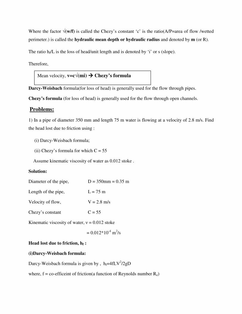
Where the factor √(w/f) is called the Chezy’s constant ‘c’ is the ratio(A/P=area of flow /wetted
perimeter.) is called the hydraulic mean depth or hydraulic radius and denoted by m (or R).
The ratio hf/L is the loss of head/unit length and is denoted by ‘i’ or s (slope).
Therefore,
Darcy-Weisbach formula(for loss of head) is generally used for the flow through pipes.
Chezy’s formula (for loss of head) is generally used for the flow through open channels.
Problems:
1) In a pipe of diameter 350 mm and length 75 m water is flowing at a velocity of 2.8 m/s. Find
the head lost due to friction using :
(i) Darcy-Weisbach formula;
(ii) Chezy’s formula for which C = 55
Assume kinematic viscosity of water as 0.012 stoke .
Solution:
Diameter of the pipe, D = 350mm = 0.35 m
Length of the pipe, L = 75 m
Velocity of flow, V = 2.8 m/s
Chezy’s constant C = 55
Kinematic viscosity of water, ν = 0.012 stoke
= 0.012*10-4 m2/s
Head lost due to friction, hf :
(i)Darcy-Weisbach formula:
Darcy-Weisbach formula is given by , hf=4fLV2/2gD
where, f = co-efficeint of friction(a function of Reynolds number Re)
Mean velocity, v=c√(mi) ���� Chezy’s formula

Re = (v*D) / ν = (2.8*0.35) / 0.012*10-4 = 8.167*105
Therefore f = 0.0719/ (Re)0.25 [use when Re > 4000]
= 0.0719/ (8.167*105)0.25
= 0.00263
Therefore head lost due to friction,
hf=(4* 0.00263*75*(2.8)2) /2*9.81*0.35
hf = 0.9 m
(ii) Chezy’s formula:
mean velocity V = C√(mi)
Where C = 55, m=A /P = (π*D2/4) /(π*D) = D/4 = 0.35/4
= 0.0875 m
Therefore 2.8 = 55√(0.0875*i)
or 0.0875*i = (2.8/55)2 = 0.00259
i = 0.00296
But i = hf/L = 0.0296
Therefore hf/75 = 0.0296
hf = 0.0296*75
hf =2.22 m
2) water flows through a pipe of diameter 300 mm with a velocity of 5 m/s. If the co-efficient of
friction is given by f = 0.015 + (0.08/ (Re)0.3) where Re is the Reynolds number, find the head
lost due to friction for a length of 10 m. Take kinematic viscosity of water as 0.01 stoke.
Solution:
Diameter of the pipe, D = 300mm = 0.30 m
Length of the pipe, L = 10 m
Velocity of flow, V = 5 m/s

Kinematic viscosity of water, ν = 0.01 stoke
= 0.01*10-4 m2/s
Head lost due to friction, hf :
Co-efficient of friction, f = 0.015+ (0.08/ (Re)0.3)
But Reynolds number, Re= ρVD/µ = VD/ν
= 5*0.3/ 0.01*10-4 = 1.5*106
f = 0.015+ (0.08/ (1.5*106)0.3)
= 0.0161
Therefore head lost due to friction,
hf = 4fLV2/2gD=4*0.0161*10*52/(0.3*2*9.81)
hf = 2.735 m
3) Water is to be supplied to the inhabitants of a college campus through a supply pipe. The
following data is given:
Distance of the reservoir from the campus = 3000 m
Number of inhabitants = 4000
Consumption of water per day of each inhabitant = 180 liters
Loss of head due to friction = 18 m
Co-efficient of friction for the pipe, f = 0.007
If the half of the daily supply is pumped in 8 hours, determine the size of the supply main.
Solution:
Distance of the reservoir from the campus = 3000 m
Number of inhabitants = 4000
Consumption of water per day of each inhabitant
= 180 liters = 0.18 m3

Therefore total supply per day = 4000*0.18 = 720 m3
Since half of the daily supply is pumped in 8 hours, therefore maximum flow for which the pipe
is to be designed,
Q = 720/ (2*8*3600)
= 0.0125 m3/s
Loss of head due to friction,
hf = 18 m
and Co-efficient of friction, f = 0.007
Diameter of the supply line, D:
Using the relation:
hf = 4fLV2/2gD
velocity of flow, V = Q/A=0.0125/ (π*D2/4) = 0.0159/D2
By substitution for loss of head due to friction
18=4*0.007*3000*(0.0159/D2)2/D*2*9.81
or D5 = (4*0.007*3000*0.01592)/(18*2*9.81)
= 6.013*10-5
Size of the supply main, D = 0.143 m = 143 mm
4) In a pipe of 300mm dia and 800m length oil of specific gravity 0.8 is flowing at the rate of
0.45 m3/s. find Head lost due to friction, and Power required to maintain the flow. Take
kinematic viscosity of oil as 0.3 stokes.
Solution:
dia of the pipe, D=0.3m
Length of the pipe, L=800m
Specific gravity of oil =0.8
Kinematic viscosity of oil ν=0.3 stokes=0.3*10-4 m2/s

Discharge Q=0.45 m3/s
Head lost due to friction, hf
Velocity, v= Q/area =0.45/(π*0.32/4) =6.366m
Reynolds number, Re=v*D/ν =6.366*0.3/0.3*10-4 =6.366*104
Coefficient of friction, f = 0.0791/(Re)0.25 = 0.0791/(6.366*104)0.25
= 0.00498
hf = 4fLv2/2gD=4* 0.00498*800*6.3662/(0.3*2*9.81) = 109.72 m
Power required ‘P’ =wQhf
w=0.8*9.81=7.848kN/m3
hf=109.72m and Q=0.43 m3/s
P=7.848*0.45*109.72
P = 387.48kW
5) A pipe conveys 0.25 kg/sec of air at 300K under an absolute pressure of 2.25bar. Calculate
minimum diameter of the pipe required if the fluid velocity is limited to 7.5 m/sec.
Solution:
Density of air ρ= P/RT= (2.25*105)/(287*300)= 2.61kg/m3
Mass flow of air, m = ρAV
0.25 =2.61*A*7.5
Min. area (A) = (0.25*1) / (2.61*7.5) = 0.01277 m2
Min. dia. =√(0.01277*4)/π = 0.1275m
= 12.75 mm
6) A closed tank of a fire engine is partly filled with water, the air space above being under
pressure. A 5 cm hose connected to the tank discharges on the roof of building 2 m above the
level of water in tank, the friction losses are 50 cm of water. What air pressure must be
maintained in the tank to deliver 15 lit/sec on a roof.

Solution:
Fig.1
Discharge, Q= 15 lit/sec= 0.015 m3/sec
Velocity in 5cm hose pipe= 0.015/[(π/4)*(0.05)2
= 7.64 m/sec
Applying Bernoulli’s theorem to section 1 and 2, taking water surface level in the tank as datum
(v12 /2g)+(p1/w)+y1 = (v2
2 /2g)+(p2/w)+y2+hf
The velocity v1 at the surface is zero.
0+(p1/w)+0 = [(7.64)2 /(2*9.81)]+0+2.05
(p1/w)= 5.48 m of water
p1 = 0.548 kg f/cm2 (air pressure in tank)
7) Find the head lost due to friction in a pipe of diameter 300mm and length 50m, through which
water is flowing at a velocity of 3m/s
(i) Darcy formula
(ii) Chezy’s formula for which C = 60
Take ν for water = 0.01 stoke.
Solution:
Given
Dia. of pipe, d = 300mm = 0.30 m

Length of pipe, L = 50 m
Velocity of pipe, V = 3 m/s
Chezy’s constant, C = 60
Kinematic viscosity, ν = 0.01 stoke = 0.01cm2/sec
(i) Darcy Formula is given by equation as
Where ‘f’ = co-efficient of friction is a function of Reynolds number, Re
But Re is given by
Value of
Head lost,
(ii) Chezy’s formula. Using equation (4)

Equating the two values of i , we have
8)Find the diameter of a pipe of length 2000m when the rate of flow of water through the pipe is
200 liters/s and the head lost due to friction is 4m.Take the value of c = 50 in chezy’s formulae.
Solution:
Length of pipe,
Discharge,
Head lost due to friction,
Value of chezy’s constant,
Let the diameter of pipe = d
Velocity of flow,
Hydraulic mean depth
Loss of head per unit length.

Chezy’s formula is given by equation (4) as
Substituting the values of V, m, i and C we get
Squaring both sides,
= 0.553 m Or
= 553 mm
9) A crude oil of kinematic viscosity 0.4 stoke is flowing through a pipe of diameter 300mm at
the rate of 300mm litres/s. find the head lost due to friction for a length of 50m of the pipe.
Solution:
given
Kinematic viscosity, v = 0.4 stoke = 0.4 cm2/s = 0.4 x 10⁻⁴ m2/s
Dia. of pipe, d = 300mm = 0.30 m
Discharge, Q = 300 liters/s = 0.3m3/s
Length of pipe, L = 50 m
Velocity of flow,
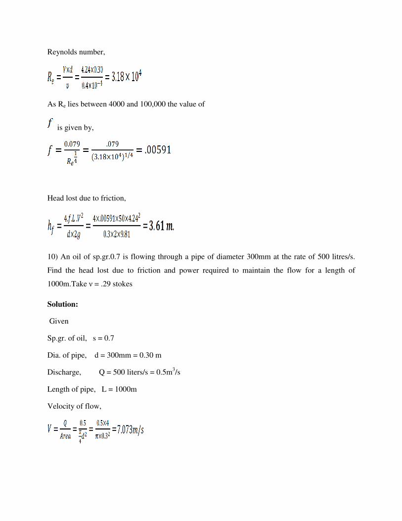
Reynolds number,
As Re lies between 4000 and 100,000 the value of
is given by,
Head lost due to friction,
10) An oil of sp.gr.0.7 is flowing through a pipe of diameter 300mm at the rate of 500 litres/s.
Find the head lost due to friction and power required to maintain the flow for a length of
1000m.Take ν = .29 stokes
Solution:
Given
Sp.gr. of oil, s = 0.7
Dia. of pipe, d = 300mm = 0.30 m
Discharge, Q = 500 liters/s = 0.5m3/s
Length of pipe, L = 1000m
Velocity of flow,

Reynolds number,
Co-efficient of friction,
Co-efficient of friction,
Head lost due to friction,
Where,
Power required P= (700*9.81*0.5*163.18/1000)=560.28 kW
6)Calculate the discharge through a pipe of diameter 200mm when the difference of pressure
head between the two ends of a pipe 500 m apart is 4m of water. Take the value of ‘f’=0.009 in
the formula,
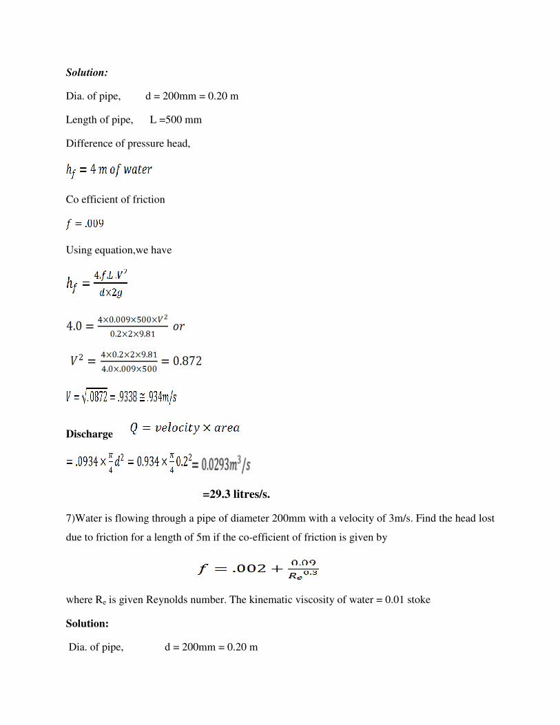
Solution:
Dia. of pipe, d = 200mm = 0.20 m
Length of pipe, L =500 mm
Difference of pressure head,
Co efficient of friction
Using equation,we have
Discharge
=29.3 litres/s.
7)Water is flowing through a pipe of diameter 200mm with a velocity of 3m/s. Find the head lost
due to friction for a length of 5m if the co-efficient of friction is given by
where Re is given Reynolds number. The kinematic viscosity of water = 0.01 stoke
Solution:
Dia. of pipe, d = 200mm = 0.20 m

Length of pipe, L = 5m
Velocity V= 3 m/s
Kinematic viscosity, ν = 0.01 stoke = 0.01 cm2/s
= 0.01*10-4 m2/s
Reynolds number,
Value of
Head lost due to friction,
8)An oil of sp.gr.0.9 and viscosity 0.06 poise is flowing through a pipe of diameter 200 mm at
the rate of 60 liters/s. Find the head lost due to friction for a 500 m length of pipe. Find the
power required to maintain this flow.
Solution:
Given: Sp.gr. of oil, soil = 0.9
Viscosity

Dia. of pipe, d = 200mm = 0.20 m
Discharge,
Length of pipe,
Density,
Reynolds number,
Where
As Re lies between 4000 and 105
The value of co-efficient of friction, f is given by
Head lost due to friction,

Power required =
Minor energy (head) losses:
The minor losses of energy are caused in the velocity of flowing fluid (either in magnitude or
direction).In case of long pipes these losses are usually quite small as compared with the loss of
energy due to friction and hence there are termed minor losses which may even be neglected
without serious error. However in small pipes these losses may sometime overweigh the friction
loss. Some of the losses of energy which may be caused due to the change of velocity are
indicated below,
Loss of head due to sudden enlargement:
he = (v12-v2
2)/2g
Fig.1: sudden enlargement
Loss of head due to sudden contraction:
when Cc given then use hc =v22/2g[vc/v2-1]2
otherwise use hc = 0.5v22/2g

Fig.2: sudden contraction
Loss of energy at the entrance of a pipe:
hi=0.5v2/2g
Loss of head at the exit of a pipe:
ho=v2/2g
Loss of energy due to gradual contraction or enlargement:
hl =k(v1-v2)2/2g
Loss of energy in bends:
hb=kv2/2g
Loss of head in various pipe fittings:
=kv2/2g where V= velocity of flow
k= co efficient
Problems on head loss due to minor losses:
1)Find the loss of head when a pipe of diameter 200mm is suddenly enlarged to a diameter of
400mm. The rate of flow of water through the pipe is 250 liters/s.

Solution:
Given:
Dia. of smaller pipe,
Area
Dia. of large pipe,
Area
Discharge,
Velocity,
Velocity,
Loss of head due to enlargement is given by equation

2) At a sudden enlargement of a water main from 240mm to 480mm diameter, the hydraulic
gradient rises by 10mm. Estimate the rate of flow.
Solution:
Given
Dia. of smaller pipe,
Area
Dia. of large pipe,
Area,
Rise of hydraulic gradient ,i.e.
Let the rate of flow = Q
Applying Bernoulli’s equation to both section,
i.e., smaller pipe section, and large pipe section.
But head loss due to enlargement

………..(2)
From continuity equation, we have
substituting this value in (ii), we get
Now substituting the value of hc and V1 in equation (1)
But hydraulic gradient rise

3) The rate of flow of water through A horizontal pipe is 0.25 m3/sec The pipe of diameter
200mm is suddenly enlarged to a diameter of pressure intensity in the smaller pipe is 11.772
N/cm2 . Determine:
• Loss of head due to sudden enlargement
• Pressure intensity in the larger pipe,
• Power lost due to enlargement.


4)A horizontal pipe of diameter 500 mm is suddenly contracted to a diameter of 250 mm. The
pressure intensities in the large and smaller pipe is given as 13.734 N/cm2 and 11.772 N/cm2
respectively. Find the loss of head due to contraction if Ce=0.62.Aiso determine the rate of flow
of water.
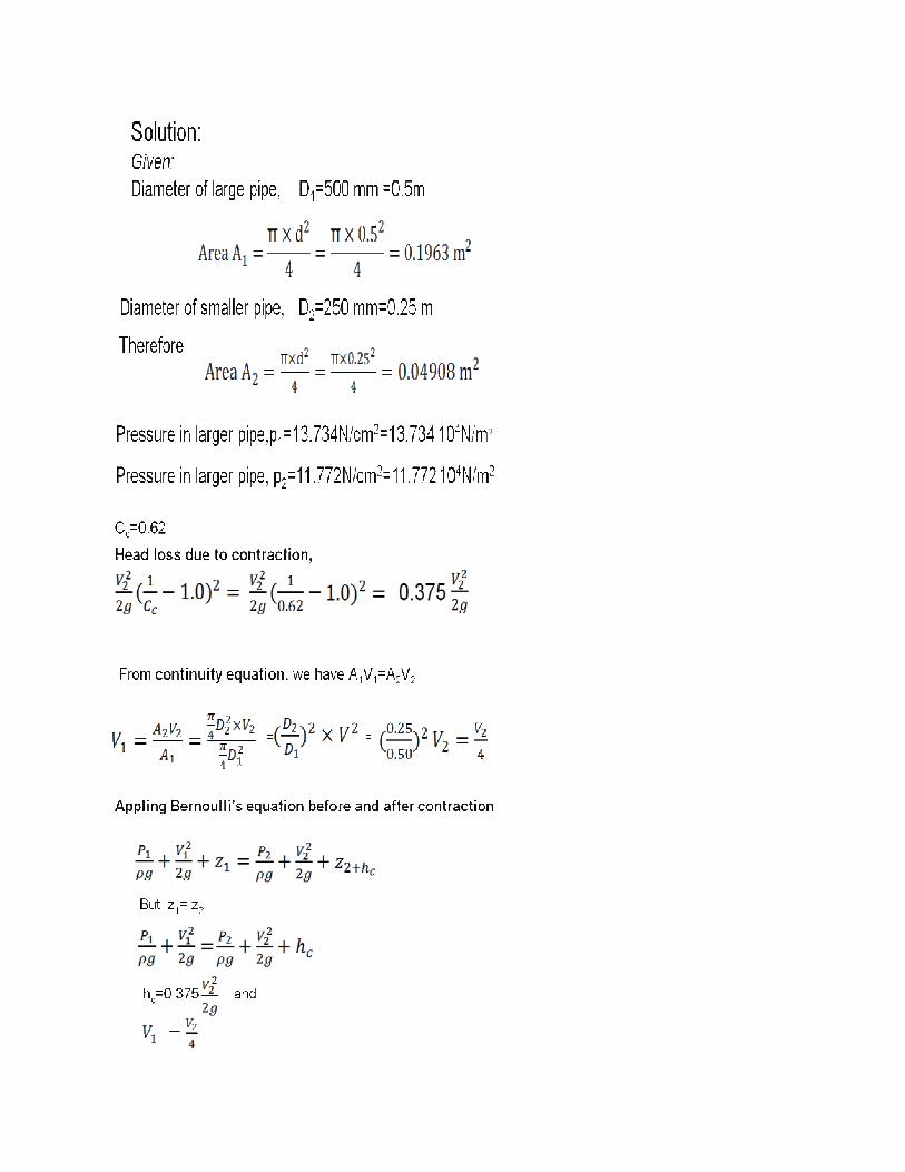

5)If in the previous problem, the rate of flow of water is 300 liters/s, other data reaming the
same, find the value of co-efficient of contraction,cc.
Solution:
Given,
D1=0.5 m, D2=0.25 m
p1=13.734 104N/m2
p2=11.772 104N/m2
Q=300 lit/s=0.3 m3/sec

Also, from the previous problem,
6)150mm diameter pipe reduces in diameter abruptly to 100mm diameter. If the pipe carries
Water at 30 liters per second, calculate the pressure loss across the contraction. Take the co-
efficient of contraction as 0.6.

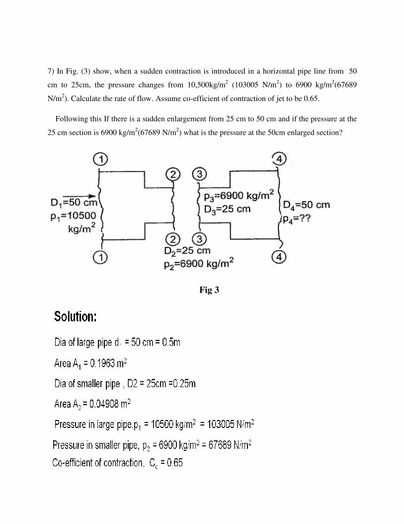
7) In Fig. (3) show, when a sudden contraction is introduced in a horizontal pipe line from 50
cm to 25cm, the pressure changes from 10,500kg/m2 (103005 N/m2) to 6900 kg/m2(67689
N/m2). Calculate the rate of flow. Assume co-efficient of contraction of jet to be 0.65.
Following this If there is a sudden enlargement from 25 cm to 50 cm and if the pressure at the
25 cm section is 6900 kg/m2(67689 N/m2) what is the pressure at the 50cm enlarged section?
Fig 3
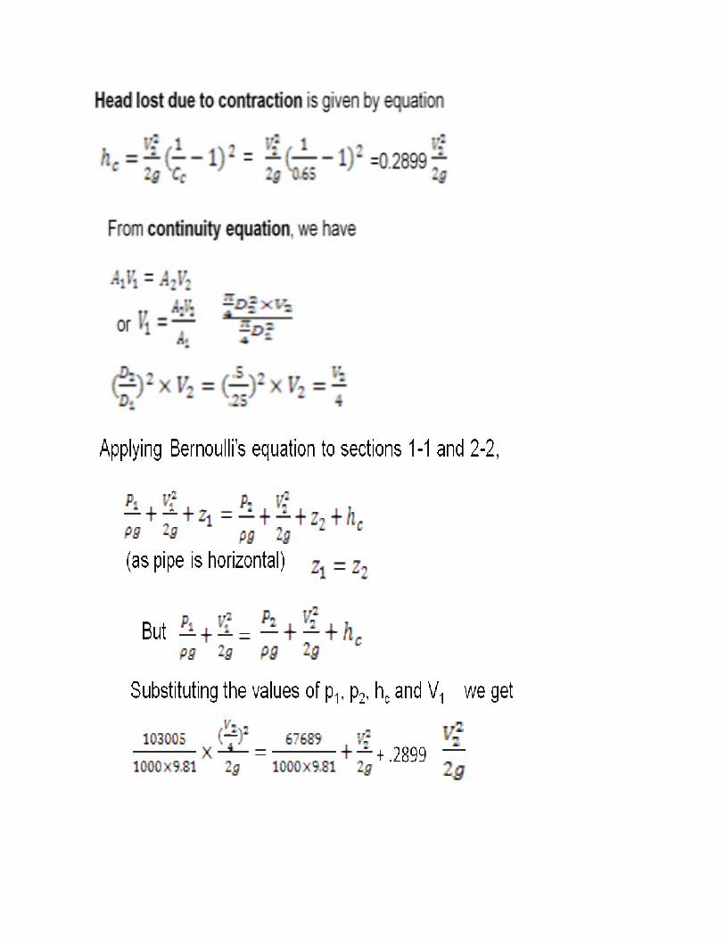

8) Determine the rate of flow of water through a pipe diameter 20 cm and length 50 m when one
end of the pipe is connected to a tank and other end of the pipe is open to the atmosphere. The
pipe is horizontal and the Height of water in the tank is 4 m above the centre of the pipe.
Consider all minor losses and take f=0.009 in the formula,

Fig 4
Solution:
Dia of pipe d = 20cm = 0.20m
Length of pipe L= 50 m
Height of water H=4 m
Co-efficient of friction, f=0.009
Let the velocity of water in the pipe =V m/s
Applying Bernoulli’s equation at the top of water surface in the tank and at the outlet of pipe, we
have [taking point 1 on the top point 2 at the outlet of pipe]
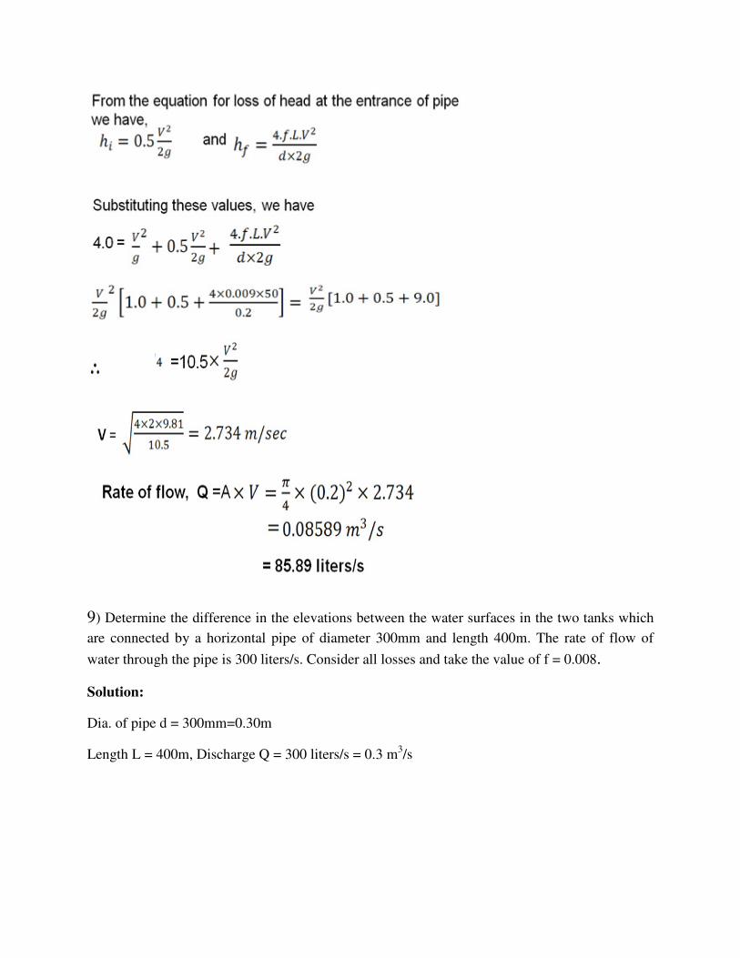
9) Determine the difference in the elevations between the water surfaces in the two tanks which
are connected by a horizontal pipe of diameter 300mm and length 400m. The rate of flow of
water through the pipe is 300 liters/s. Consider all losses and take the value of f = 0.008.
Solution:
Dia. of pipe d = 300mm=0.30m
Length L = 400m, Discharge Q = 300 liters/s = 0.3 m3/s
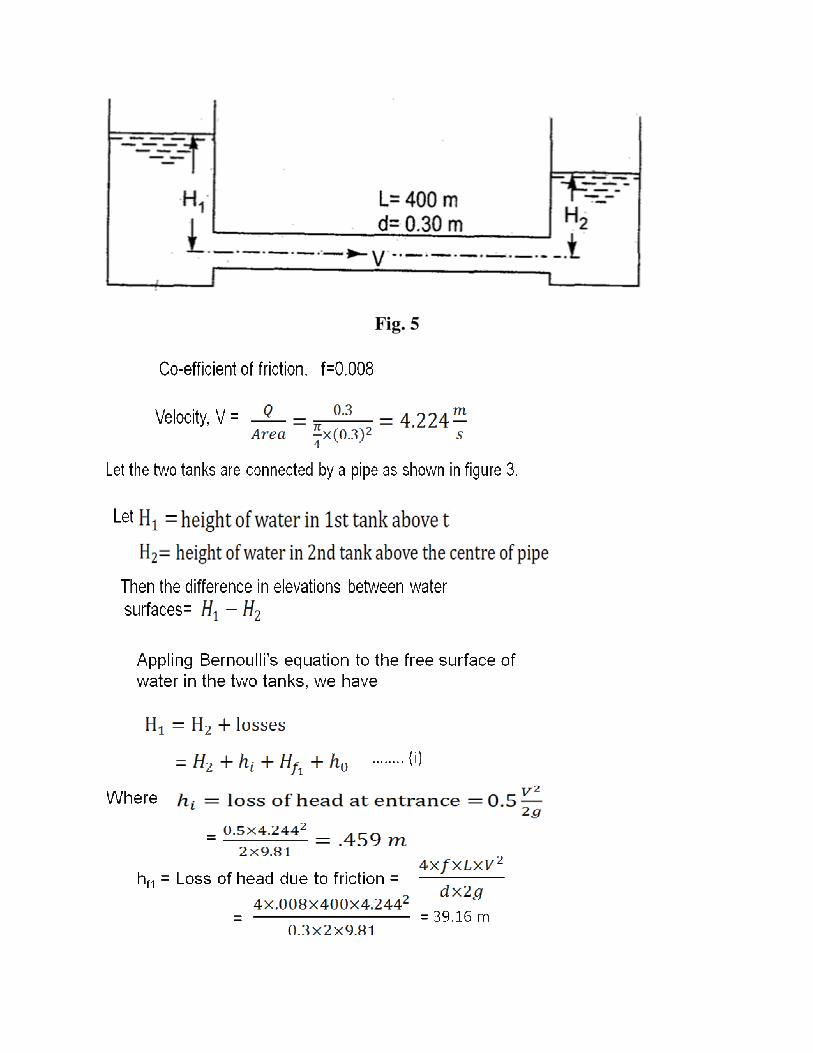
Fig. 5

10) The friction factor for turbulent flow through rough pipes can be determined by karman-
prandtl
Where f = friction factor, R0 = pipe radius, k = average roughness Two reservoirs with a
surface level difference of 20 m are to be connected by 1 m diameter pipe6 km long. What will
be the discharge when a cast iron pipe of roughness k = 0.3 mm is used? What will be the
percentage increase in the discharge if the cast iron pipe is replaced by a steel pipe of Roughness
k = 0.1 mm? Neglect all local losses.
Solution:
Difference in levels, h=20 mm
Dia of pipe, d=1.0 m
Length of pipe, L =6km=6 x 1000=6000m
Roughness of cast iron pipe, k=0.3 mm
Roughness of steel pipe, k=0.1 mm


11).A horizontal pipeline 40m long is connected to a water tank at one end and discharge freely
into the atmosphere at the other end. For the first 25 m of its length from the tank, the pipe is
150mm diameter and its diameter is suddenly enlarged to 300mm. The height of water level in
the tank is 8m above the centre of the pipe. Considering all losses of head which occurs
determine the rate of flow, take f=0.01 for both section of the pipe.
Fig. 6
Solution:
Given:
Total length of pipe, L = 40m
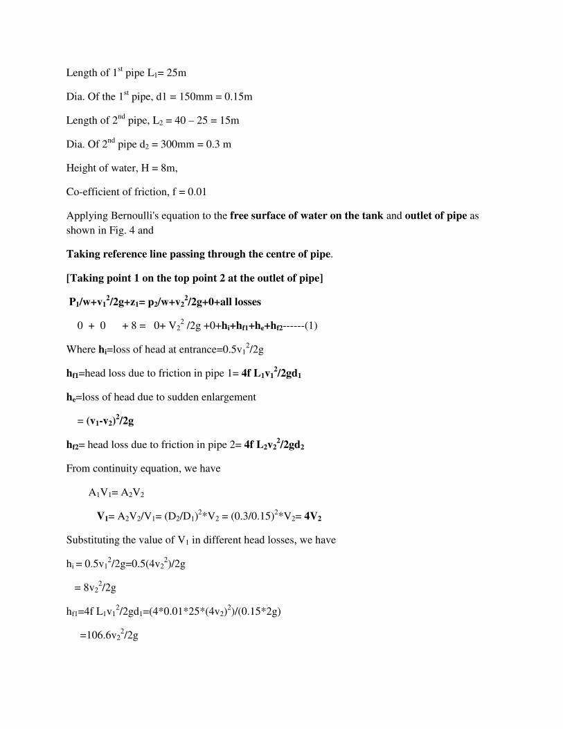
Length of 1st pipe L1= 25m
Dia. Of the 1st pipe, d1 = 150mm = 0.15m
Length of 2nd pipe, L2 = 40 – 25 = 15m
Dia. Of 2nd pipe d2 = 300mm = 0.3 m
Height of water, H = 8m,
Co-efficient of friction, f = 0.01
Applying Bernoulli's equation to the free surface of water on the tank and outlet of pipe as
shown in Fig. 4 and
Taking reference line passing through the centre of pipe.
[Taking point 1 on the top point 2 at the outlet of pipe]
P1/w+v12/2g+z1= p2/w+v2
2/2g+0+all losses
0 + 0 + 8 = 0+ V22 /2g +0+hi+hf1+he+hf2------(1)
Where hi=loss of head at entrance=0.5v12/2g
hf1=head loss due to friction in pipe 1= 4f L1v12/2gd1
he=loss of head due to sudden enlargement
= (v1-v2)2/2g
hf2= head loss due to friction in pipe 2= 4f L2v22/2gd2
From continuity equation, we have
A1V1= A2V2
V1= A2V2/V1= (D2/D1)2*V2 = (0.3/0.15)2*V2= 4V2
Substituting the value of V1 in different head losses, we have
hi = 0.5v12/2g=0.5(4v2
2)/2g
= 8v22/2g
hf1=4f L1v12/2gd1=(4*0.01*25*(4v2)
2)/(0.15*2g)
=106.6v22/2g

he= (v1-v2)2/2g=(4v2-v2)
2/2g
= 9v22/2g
hf2= 4fl2v22/2gd2=4*0.01*15*v2
2/(0.3*2g)
= 2v22/2g
Substituting the value of the losses in equation (1), we get
8=v22/2g+ 8v2
2/2g+106.6v22/2g+9v2
2/2g+2v22/2g
=v22/2g(1+8+106.6+9+2)
=126.6v22/2g
V2=√(8*2g)/126.6
=√(8*2*9.81)/126.6
V2 =1.11 m/s
Hence rate of flow ‘Q’=A2v2=(π*(0.3)2/4)*1.11
Q=0.078m3/s
Q= 78.67 liters/s
12) Design the diameter of a steel pipe to carry water having kinematic viscosity ν =10-6 m2/sec
With a mean velocity of 1 m/s. The head loss is to be limited to 5 m per 100 m length of pipe.
Consider the equivalent sand roughness height of pipe ks= 45 x 10-4 cm. Assume that the
Darcy weisbach friction factor over the whole range of turbulent flow can be expressed as
Solution:
Given:
Kinematic viscosity,
Mean velocity, V =1 m/s.
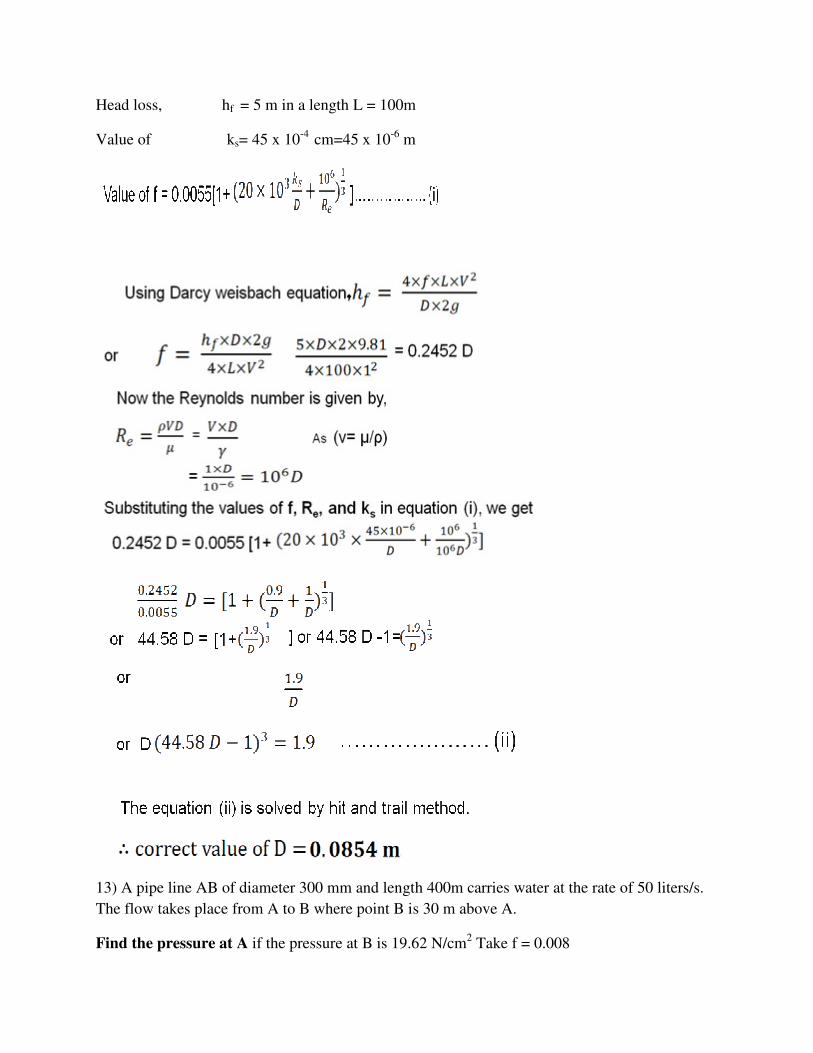
Head loss, hf = 5 m in a length L = 100m
Value of ks= 45 x 10-4 cm=45 x 10-6 m
13) A pipe line AB of diameter 300 mm and length 400m carries water at the rate of 50 liters/s.
The flow takes place from A to B where point B is 30 m above A.
Find the pressure at A if the pressure at B is 19.62 N/cm2 Take f = 0.008

Fig 7
Solution:
Given:
Dia.of pipe, d = 300 mm = 0.30 m
Length of pipe, L = 400 m
Discharge, Q = 50 liters/s = 0.05 m3/sec
Pressure at B, PB = 19.62N/cm2 = 19.62 x 10⁴ N/m2
F = 0.008
Appling Bernoulli’s equation at points A and B
And taking datum line passing through A, we have

Hydraulic gradient line (H.G.L):
It is defined as the line which gives the sum of pressure head (p/w) and datum head (z) of a
flowing fluid in pipe with respect to some reference or it is line which is obtained by joining the
top of all vertical ordinates, showing the pressure head(p/w) of a flowing fluid in a pipe from the
centre of the pipe. The line so obtain is called the H.G.L.
Total energy loss (TEL or EGL)
It is known that the total head (which is also total energy per unit weight) with respect to any
arbitrary datum, is the sum of the elevation (potential) head, pressure head and velocity head.
Total head = P/w+Z+v2/2g
When the fluid flows along the pipe there is loss of head (energy) and the total energy decreases
in the direction of flow. If the total energy at various parts along the axis of the pipe is plotted
and joined by a line, the line so determined is called the Energy gradient (E.G.L) is also called
total energy line (TEL).
Points are worth noting
• Energy gradient like always drops in direction of flow because of loss of head.
• HGL may rise or fall depending upon the pressure change.

• HGL is always below the Energy Gradient
Problems on H.G.L and T.E.L
1) Determine the rate of flow of water through a pipe diameter 20 cm and length 50 m when one
end of the pipe is connected to a tank and other end of the pipe is open to the atmosphere. The
pipe is horizontal and the Height of water in the tank is 4 m above the centre of the pipe.
Consider all minor losses and take f=0.009 in the formula,
Draw the hydraulic gradient line (H.G.L) and total energy line (T.E.L)
Fig 1
Solution:
Dia of pipe d = 20cm = 0.20m
Length of pipe L= 50 m
Height of water H=4 m
Co-efficient of friction, f=0.009
Let the velocity of water in the pipe =V m/s

Applying Bernoulli’s equation at the top of water
Surface in the tank and at the outlet of pipe, we have
[Taking point 1 on the top point 2 at the outlet of pipe]
Considering datum line passing through the centre of pipe
4.0 =
But the velocity in pipe =V,
Therefore V= V2
Therefore
From the equation for loss of head at the entrance of pipe
We have,
and
Substituting these values, we have

Velocity, V through pipe is calculated and its value is V=2.734 m/s.
And
hf = head loss due to friction
(a) Total energy line (T. E. L.). consider three points, A, B, and C on the free surface of
water in the tank, at the inlet of the pipe and at the outlet of the pipe respectively as
shown in the fig. us find total energy at these points, taking the centre of pipe as the
reference line.
1) Total energy at A
A =
2) Total energy at B = Total energy at A- hi
3) Total energy at C,

Hence total energy line will be coinciding with free surface of water in the tank. At the
inlet of the pipe, it will decrease by
hi (=.19 m) from free surface and at outlet of pipe total energy is 0.38 m. Hence in the fig.
• Point D represents total energy at A
• Point E, where DE = hi represents total energy at inlet of the pipe
• Point F, where CF = 0.38 represents total energy at outlet of the pipe
Join D to E and E to F .Then
DFE represents the total energy line.
(b) Hydraulic gradient line (H.G.L.). H.G.L. gives the sum
( ) with reference to the datum- line.
Hence hydraulic gradient line is obtained by subtracting from total energy line. V2/2g
At the outlet of the pipe, total energy is V2/2g By subtracting V2/2g
From total energy at this point, we shall get point C. which lies on the center line of pipe.
From C, draw a line CG parallel to EF.
Then CG represents the hydraulic gradient line.
2)A horizontal pipeline 40m long is connected to a water tank at one end and discharge
freely into the atmosphere at the other end. For the first 25 m of its length from the tank,
the pipe is 150mm diameter and its diameter is suddenly enlarged to 300mm. The height
of water level in the tank is 8m above the centre of the pipe. Considering all losses of
head which occurs determine the rate of flow, take f=0.01 for both section of the pipe.
Draw the hydraulic gradient and total energy line.

Solution:
Given:
Total length of pipe, L = 40m
Length of 1st pipe L1= 25m
Dia. of the 1st pipe, d1 = 150mm = 0.15m
Length of 2nd pipe, L2 = 40 – 25 = 15m
Dia. of 2nd pipe d2 = 300mm = 0.3 m
Height of water, H = 8m,
Co-efficient of friction, f = 0.01
Applying Bernoulli's equation to the free surface of water on the tank and outlet of pipe
as shown in Fig. 4 and
Taking reference line passing through the centre of pipe.
[Taking point 1 on the top point 2 at the outlet of pipe]
P1/w+v12/2g+z1= p2/w+v2
2/2g+0+all losses
0 + 0 + 8 = 0+ V22 /2g +0+hi+hf1+he+hf2------ (1)
Where hi=loss of head at entrance=0.5v12/2g
hf1=head loss due to friction in pipe 1= 4f L1v12/2gd1
he=loss of head due to sudden enlargement
= (v1-v2)2/2g
hf2= head loss due to friction in pipe 2= 4f L2v22/2gd2
From continuity equation, we have
A1V1= A2V2
V1= A2V2/V1= (D2/D1)2*V2 = (0.3/0.15)2*V2= 4V2
Substituting the value of V1 in different head losses, we have
hi = 0.5v12/2g=0.5(4v2
2)/2g
= 8v22/2g
hf1=4f L1v12/2gd1=(4*0.01*25*(4v2)
2)/(0.15*2g)

=106.6v22/2g
he= (v1-v2)2/2g=(4v2-v2)
2/2g
= 9v22/2g
hf2= 4fL2v22/2gd2=4*0.01*15*v2
2/(0.3*2g)
= 2v22/2g
Substituting the value of the losses in equation (1), we get
8=v22/2g+ 8v2
2/2g+106.6v22/2g+9v2
2/2g+2v22/2g
=v22/2g (1+8+106.6+9+2)
=126.6v22/2g
V2=√(8*2g)/126.6
=√ (8*2*9.81)/126.6
V2 =1.11 m/s
Hence rate of flow ‘Q’=A2v2= (π*(0.3)2/4)*1.11
Q=0.078m3/s
Q= 78.67 liters/s
V1 = 4V2 = 4 x 1.113 = 4.452 m/s
The various head losses are
ho =
Total Energy Line
• Point A lies on free surface of water.
• Take AB = hi = 0.5 m
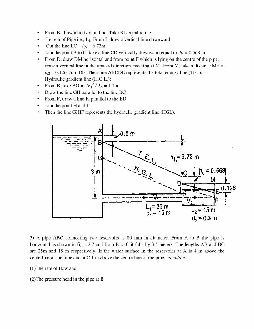
• From B, draw a horizontal line. Take BL equal to the
• Length of Pipe i.e., L1. From L draw a vertical line downward.
• Cut the line LC = hf1 = 6.73m
• Join the point B to C. take a line CD vertically downward equal to he = 0.568 m
• From D, draw DM horizontal and from point F which is lying on the centre of the pipe,
draw a vertical line in the upward direction, meeting at M. From M, take a distance ME =
hf2 = 0.126. Join DE. Then line ABCDE represents the total energy line (TEL).
Hydraulic gradient line (H.G.L.):
• From B, take BG = V12 / 2g = 1.0m
• Draw the line GH parallel to the line BC
• From F, draw a line Fl parallel to the ED.
• Join the point H and I.
• Then the line GHIF represents the hydraulic gradient line (HGL).
3) A pipe ABC connecting two reservoirs is 80 mm in diameter. From A to B the pipe is
horizontal as shown in fig. 12.7 and from B to C it falls by 3.5 meters. The lengths AB and BC
are 25m and 15 m respectively. If the water surface in the reservoirs at A is 4 m above the
centerline of the pipe and at C 1 m above the centre line of the pipe, calculate:
(1)The rate of flow and
(2)The pressure head in the pipe at B

Neglect the loss at the bend but consider all other losses. Also draw the energy and hydraulic
gradient lines. Take Darcy friction factor F = 0.024 and Entrance = 0.5
Solution:
Diameter of the pipe, D = 80 mm = 0.8 m
Area, A = π/4 *0.082 =0.00026 m2
Friction factor (=4f), = 0.024
Kentrance = 0.5
(1) The rate of flow Q:
Applying Bernoulli’s equation between the water surfaces 1 and 2 in the two reservoirs
(considering horizontal plane through C as datum), we get
p1/w + v12/(2g) + z1 = p2/w + v2
2/(2g)+ z2 + loss at entrance + hf (loss due to friction) + v2/(2g)
0+0+(4+3.5–1)=0+0+0+0.5v2/(2g)+{4fLv2/(D*2g)}+v2/(2g)
(Where v = velocity of flow in the pipe)
or 6.5 = 0.5v2/(2g)+ {0.024*(25+15)*v2}/(0.08*2g) + v2/(2g)
= v2/(2g)(0.5+12+1) + 13.5 v2/(2g)
v2 =6.5*2*9.81/13.5= 9.446

v = 3.073 m/s
Therefore, flow rate= A* V = 0.005026*3.073 = 0.01544 m3/s
(2)Pressure head in the pipe at B,
Applying Bernoulli’s equation at 1 and B, we get
p1/w+v12/(2g) +z1 = pB/w+vB
2/(2g)+zB+0.5v2/(2g)+hf
0+0+4 = pB/w+v2/(2g)+z+0.5v2/(2g)+4fLv2/(D*2g)
4 = pB/w+(v2/2g)+(0.5v2/2g)+{0.024*25*v2/(0.08*2g)}
(vB = v = 3.073m/s)
4 = pB/w+(v2/2g)+(0.5v2/2g)+(7.5v2/2g)
= pB/w+(9v2/2g)
pB/w = 4 - (9v2/2g)
= 4 - (9*3.0732/2*9.81)
pB/w = - 0.33 m of water (below atmosphere)
Energy gradient and hydraulic gradient lines (E.G.L. and H.G.L):
For plotting E.G.L and H.G.L., we require the velocity head, (same throughout)
v2/2g = 3.0732/(2*9.81) = 0.481 m
Total energy at B with respect to horizontal datum through C
= 3.5+pB/w+v2/2g = 3.5- 0.33+ 3.0732/(2*9.81)
= 3.65 m
4) A pipe line, 300 mm in diameter and 3200 m long is used to pump up 50kg per second of oil
whose density is 950 kg/m3 and whose kinematic viscosity is 2.1 strokes. The centre of the
pipe line at the upper end is 40m above than that at the lower end. The discharge at the upper
end is atmospheric. Find the pressure at the lower end and draw the hydraulic gradient and
the total energy line.

Solution
Given:
Dia. of pipe. D =300mm = 0.3m
Length of pipe, L = 3200m
Mass, M = 50kg/s = ρ. Q
Density, ρ = 950kg/m3
Discharge, Q = 50/ρ = 50/950 = 0.0523 m3/s
Kinematic viscosity, ν = 2.1 stokes = 2.1 cm2/s
=2.1*10-4 m2/s
Height of upper end = 40m
Pressure at upper end = atmospheric = 0
Reynolds number, Re = V*d/ ν
Where V=Discharge/area= 0.0526/3.14*0.32=0.744 m/s
Re = 0.744*0.30/2.1*10-4=1062.8

Coefficient of friction, f =16/Re=16/1062.8 = 0.015
Head lost due to friction, hf = 4*f*L*V2/d*2g
hf =4*0.015*3200*0.7442/0.3*2*9.81=18.05 m of oil
Applying the Bernoulli’s equation at the lower and upper end of the pipe and taking datum line
passing through the lower end, we have
p2 = 0, hf = 18.05m
But Z1= 0, Z2= 40m, V1=V2 as diameter is same
Substituting these values, we have
=40+18.05=58.05 m of oil
p1 = 58.05*ρ g =58.05*950*9.81 [ρ for oil =950]
= 540997 N/m2 =540997/10-4 N/cm2
= 54.099 N/cm2. Ans
H.G.L and T.E.L
V2/2g = 0.7442 / 2 x 9.81 = 0.0282 m
H.G.L and T.E.L
V2/2g = 0.7442 / 2 x 9.81 = 0.0282 m
P1/ ρg = 58.05 m of oil
P2/ ρg = 0
Draw a horizontal line AX as shown in fig.8 . From A, draw a centre line of the pipe in such a
way that point C is a distance of 40m above the horizontal line. Draw a vertical line AB through
A such that AB = 58.05m. Join B with C. Then BC is the hydraulic gradient line .
Draw a line DE parallel to BC at a height of 0.0282 m above the hydraulic gradient line. Then
DE is the total energy line.

Fig 8
5)Two reservoirs A and C having a difference of level of 15.5 m are connected by a pipe line
ABC the elevation of point B being 4.0 m below the level of water in reservoir A. The length AB
of the pipe line is 250 m, the pipe being made of mild steel having a friction co-efficient f1 ,
while the length BC is 450 m the pipe having made of cast iron having a friction co-efficient f2.
Both the lengths AB and BC have a diameter of 200mm. A partially Closed valve is located BC
at a distance of 150m from reservoir C. If the flow through the pipeline is 3m3/min, the pressure
head at B is 0.5m and the head loss at the valve is 5.0m.
Find the friction co- efficient f1 and f2; Draw the hydraulic grade line of the pipe line and indicate
on the diagram head loss values at significant points. Take into account head loss at entrance and
exit points of the pipeline.
Solution:
Difference of water level between two reservoirs = 15.5m
Diameter of the pipeline ABC, D=200mm=0.2m
Length AB, LAB=250m
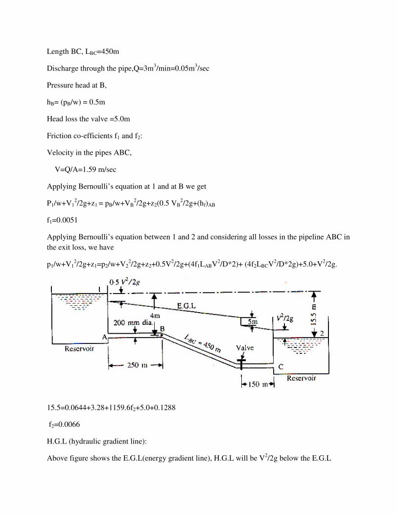
Length BC, LBC=450m
Discharge through the pipe,Q=3m3/min=0.05m3/sec
Pressure head at B,
hB= (pB/w) = 0.5m
Head loss the valve =5.0m
Friction co-efficients f1 and f2:
Velocity in the pipes ABC,
V=Q/A=1.59 m/sec
Applying Bernoulli’s equation at 1 and at B we get
P1/w+V12/2g+z1 = pB/w+VB
2/2g+z2(0.5 VB2/2g+(hf)AB
f1=0.0051
Applying Bernoulli’s equation between 1 and 2 and considering all losses in the pipeline ABC in
the exit loss, we have
p1/w+V12/2g+z1=p2/w+V2
2/2g+z2+0.5V2/2g+(4f1LABV2/D*2)+ (4f2LBCV2/D*2g)+5.0+V2/2g.
15.5=0.0644+3.28+1159.6f2+5.0+0.1288
f2=0.0066
H.G.L (hydraulic gradient line):
Above figure shows the E.G.L(energy gradient line), H.G.L will be V2/2g below the E.G.L

6) The difference in water surface levels in two tanks, which are connected by three pipes in
series of lengths 300m, 170 m and 210 m and of diameters 300 mm, 200 mm and 400 mm
respectively, is 12 m. Determine the rate of flow of water if the co-efficient of friction are 0.005,
0.0052 and 0.0048 respectively, considering:
(i) Minor losses
(ii) Neglecting minor losses
Fig 9
Solution
Given :
Difference of water level, H = 12 m
Length of pipe 1, L1 = 300 m and
dia. of pipe 1, d1 = 300 mm =0.3 m
Length of pipe 2, L2 = 170 m and
dia. of pipe 2 d2 = 200 mm =0.2 m

Length of pipe 3, L3 = 210 m and
dia. of pipe 3, d3 = 400 mm = 0.4 m
Also,
f1 = 0.005, f2 = 0.0052 and f3 = 0.0048
(i) Considering Minor Losses. Let V1, V2 and V3 are the
Velocities in the first second and third pipe respectively
From continuity equation, we have
A1V1 = A2V2 =A3V3
V2 = A1V1/A2 = V1 = (V1)
= (0.3/0.2)2 * V1 = 2.25V1
V3 = A1V1/A3 = d12/d3
2(v1)
= (90.3/0.4)2 V1 =0.5625 V1
The difference in liquid surface levels is equal to the sum of the total head loss in the pipes
H= [ ]
Substituting V2 and V3,
or

12= [118.887]
V1= = 1.407 m/s
Therefore,
Rate of flow, Q = Area * velocity = A1 * V1
= π /4 (d1)2 * V1 = π/4 (0.3 )2 *1.407 = 0.09945 m3/s
Q = 99.45 liters/s.
(ii) Neglecting Minor Losses. Using equation we have
h = 4 x f1 xL1 x v12 / d1 x 2 x 9.81 + 4 x f2 x L 2 x v2
2 / d2 x 2 x 9.81
+ 4 x f3 x L 2 x v22 / d3 x 2 x 9.81
= [20.0+89.505+3.189] =
V1 = = 1.445 m/s
Discharge, Q = V1 *A1
= 1.445 * π / 4 (0.32)
= 0.1021 m3/s
Q = 102.1 litres /s
7) Three pipes of 400 mm, 200 mm and 300 mm diameters have lengths of 400m, 200m and 300
m respectively. They are connected in series to make a compound pipe. The ends of this
compound pipe are connected with two tanks whose difference of water levels is 16 m.
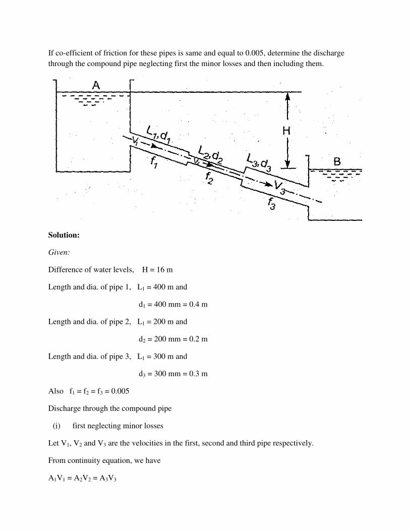
If co-efficient of friction for these pipes is same and equal to 0.005, determine the discharge
through the compound pipe neglecting first the minor losses and then including them.
Solution:
Given:
Difference of water levels, H = 16 m
Length and dia. of pipe 1, L1 = 400 m and
d1 = 400 mm = 0.4 m
Length and dia. of pipe 2, L1 = 200 m and
d2 = 200 mm = 0.2 m
Length and dia. of pipe 3, L1 = 300 m and
d3 = 300 mm = 0.3 m
Also f1 = f2 = f3 = 0.005
Discharge through the compound pipe
(i) first neglecting minor losses
Let V1, V2 and V3 are the velocities in the first, second and third pipe respectively.
From continuity equation, we have
A1V1 = A2V2 = A3V3

= (0.4/0.2)2 V1 = 4V1
= (0.4/0.2)2 V1 = 1.77 V1
Using equation, we have
h = 4 x f1 xL1 x v12 / d1 x 2 x 9.81 + 4 x f2 x L 2 x v2
2 / d2 x 2 x 9.81 + 4 x f3 x L 2 x v22 / d3 x 2 x
9.81
V1 = =0.882 m/s
Therefore, Discharge, Q = A1 * V1 = π / a *( 0.4)2 * 0.882
= 0.1108 m3/s
Discharge through the compound pipe
(ii) Considering minor losses
Minor losses are:
(a) At inlet, hi ( 0.5*V12)/2*g
(b) Between first pipe and second pipe, due to contraction,
hc=(0.5V22)/(2*g)=(0.5*(4V1
2))/(2*g)

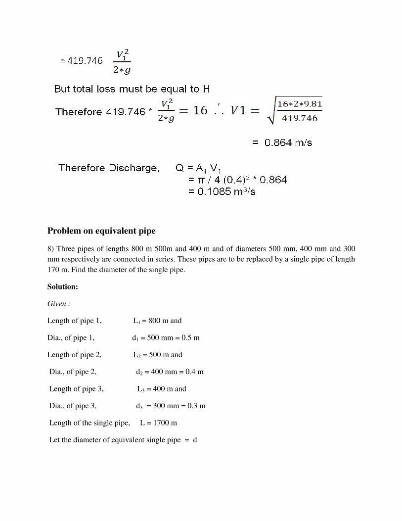
Problem on equivalent pipe
8) Three pipes of lengths 800 m 500m and 400 m and of diameters 500 mm, 400 mm and 300
mm respectively are connected in series. These pipes are to be replaced by a single pipe of length
170 m. Find the diameter of the single pipe.
Solution:
Given :
Length of pipe 1, L1 = 800 m and
Dia., of pipe 1, d1 = 500 mm = 0.5 m
Length of pipe 2, L2 = 500 m and
Dia., of pipe 2, d2 = 400 mm = 0.4 m
Length of pipe 3, L3 = 400 m and
Dia., of pipe 3, d3 = 300 mm = 0.3 m
Length of the single pipe, L = 1700 m
Let the diameter of equivalent single pipe = d

9).A main pipe divided into two parallel pipes which again forms one pipe as shown in fig. 3.
The length and diameter for the first parallel pipe are 2000m and 1.0 m respectively, while the
length and diameter of 2nd parallel pipe are 2000 m and 0.8 m. Find the rate of flow in each
parallel pipe, if total flow in the main is 3.0 m3/s . The co efficient of friction for each parallel
pipe is same and equal to 0.005.

The rate of flow in the main pipe is equal to the sum of rate of flow through branch pipes =
We have,
h = 4 x f1 xL1 x v12 / d1 x 2 x 9.81 + 4 x f2 x L 2 x v2
2 / d2 x 2 x 9.81

10). A pipe line of 0.6 m diameter is 1.5 km long. To increase the discharge, another line of the
same diameter is introduced parallel to the first in the second half of the length. Neglecting
minor losses. Find the increase in discharge if 4f = 0.04. The head at inlet is 300mm.
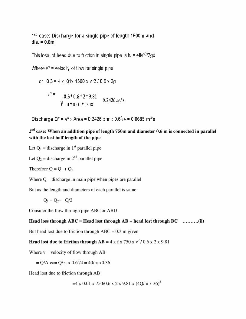
2nd case: When an addition pipe of length 750m and diameter 0.6 m is connected in parallel
with the last half length of the pipe
Let Q1 = discharge in 1st parallel pipe
Let Q2 = discharge in 2nd parallel pipe
Therefore Q = Q1 + Q2
Where Q = discharge in main pipe when pipes are parallel
But as the length and diameters of each parallel is same
Q1 = Q2= Q/2
Consider the flow through pipe ABC or ABD
Head loss through ABC = Head lost through AB + head lost through BC ……….(ii)
But head lost due to friction through ABC = 0.3 m given
Head lost due to friction through AB = 4 x f x 750 x v2 / 0.6 x 2 x 9.81
Where v = velocity of flow through AB
= Q/Area= Q/ π x 0.62/4 = 40/ π x0.36
Head lost due to friction through AB
=4 x 0.01 x 750/0.6 x 2 x 9.81 x (4Q/ π x 36)2

= 31.87 Q2
Head lost due to friction through BC = 4 x f x L1 x v12 / d x 2 x g
=4 x 0.01 x 750/0.6 x 2 x 9.81 [(Q/2 x π/4 x 0.62 ]
( as v1 = Discharge / (π/4(0.6)2 = Q/2 x π/4(0.6)2 )
= 7.969 Q2
11). A pipe of diameter 20 cm and length 2000m connects two reservoirs, having difference of
water levels as 20. Determine the discharge through the pipe. If an additional pipe of diameter 20
cm and length 2000 m is attached to the last 1200m length of the existing pipe, find the increase
in the discharge . Take f = 0.015 and Neglect minor losses
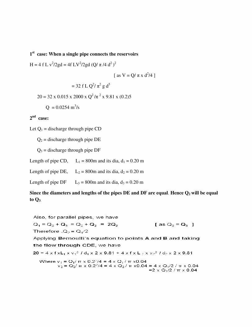
1st case: When a single pipe connects the reservoirs
H = 4 f L v2/2gd = 4f LV2/2gd (Q/ π /4 d2 )2
[ as V = Q/ π x d2/4 ]
= 32 f L Q2/ π2 g d5
20 = 32 x 0.015 x 2000 x Q2 /π 2 x 9.81 x (0.2)5
Q = 0.0254 m3/s
2nd case:
Let Q1 = discharge through pipe CD
Q2 = discharge through pipe DE
Q3 = discharge through pipe DF
Length of pipe CD, L1 = 800m and its dia, d1 = 0.20 m
Length of pipe DE, L2 = 800m and its dia, d2 = 0.20 m
Length of pipe DF L3 = 800m and its dia, d3 = 0.20 m
Since the diameters and lengths of the pipes DE and DF are equal. Hence Q2 will be equal
to Q3.

Flow Through branched pipes
12) Three reservoirs A, B, and C are connected by a pipe system shown in the fig 17.find the
discharge into or from the reservoirs B and C if the rate of flow from reservoirs A is 60 liters/s.
Find the height of water level in the reservoir C. Take f=.006 for all pipes.

Solution:
Given:
Length of pipe AD, L1=1200m
Dia. of pipe AD,
D1 = 30 cm =0.30 m
Discharge through AD, Q1 = 60 liters = 0.06 m3/s
Height of water level in A from reference line, zA = 40m
For pipe DB, length, L2 = 600m, d2 = 20cm=0.20m, ZB = 38.0
For pipe DC, length, L3 = 800m, d3 = 30cm=0.30m
Hence piezometric head at D = 36.482.
but ZB=38m
Hence water flows from B to D.
Appling Bernoulli’s equations to point B and D

Appling Bernoulli’s equations to point D and C,
where, V3 = Q3 / (π /4 x d32)

Unit 7: Intoduction to compressible flow
Introduction :
Consider a ideal gas equation
It seen that density is depends directly on pressure and inversely on temperature. Thus density
changes in the flow can in fact occur . Such flows called compressible flows
Compressible flow is defined as the flow in which the density of the fluid does not remain
constant during flow. This means that the density changes from point to point in compressible
flow. But in case of incompressible flow, the density of the fluid is assumed to be constant. In
fluid flow measurements, flow passed immersed bodies, viscous flow etc,
Attributes of Compressible Flow
• Density can no longer be regarded as constant.
• Bernoulli’s principle doesn’t hold for compressible flow.
• Coupling between Internal energy and Kinetic energy can
no longer be ignored.
• The change in density of a fluid is accompanied by the changes in pressure and
temperature and hence the thermodynamic behavior of the fluid will have to be taken into
consideration
A study of compressible flow is so important because of the wide range examples that exist:
• natural gas piped from producer to consumer,
• high speed flight through air,
• discharging of compressed gas tanks,
• flow of air through compressor,

• flow of gases/steam through turbine, in machines , and many others
• Flow of gases through orifices and nozzles,
• Projectiles and airplanes flying at high altitudes with high
velocities, the density of the fluid changes during the flow.
Basic Thermodynamic Relations
(1)Equation of state- is defined as the equation which gives the relationship between the
pressure, temperature ans specific volume of gas. For the perfect gas, the equation of state is
where
Vs = Specific volume or volume per unit mass = 1/ρ
p = Absolute pressure of gas in kgf/m2 abs
T = Absolute temperature=(t+273)˚C ,absolute =Degrees Kelvin (˚K)
R = Gas constant in kgf-m/kg ˚K or (j/kg K)
• The value of gas constant R is different for each gas. For air having specific weight w
of 1.293 (12.68 ) at a pressure of 760 mm of Hg (or 10,332 kgf/ or 101,300 ) and
temperature 0˚C, the gas constant will be
= = or
Therefore R = 29.27 if the value of R is given as 29.27 kgf-m/kg ˚K for air, value of p and
ρ should be taken Kgf/m2 and kg/m3
• If the weight of gas is known as W, then total volume of the gas is v. Then equation (1)
can be written in the form
………. (2)
In addition to above equation of state, certain other basic relationships of
thermodynamics are also required. They are briefly described below for the purpose of
revision.
2 (a) Isothermal Process - In this process the temperature remains always constant. It
means that when a gas is compressed sufficient time is allowed to dissipate the amount of
heat generated due to compression, to the atmosphere.
Equation of state for this case is
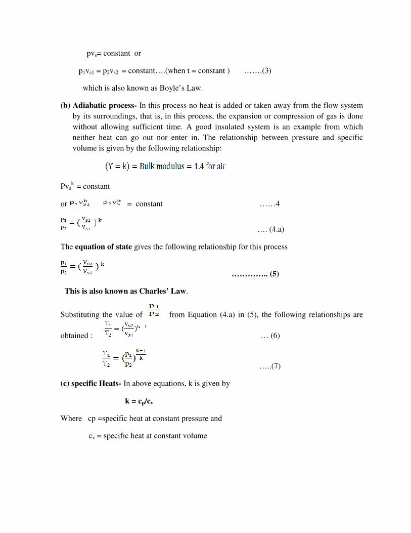
pvs= constant or
p1vs1 = p2vs2 = constant….(when t = constant ) …….(3)
which is also known as Boyle’s Law.
(b) Adiabatic process- In this process no heat is added or taken away from the flow system
by its surroundings, that is, in this process, the expansion or compression of gas is done
without allowing sufficient time. A good insulated system is an example from which
neither heat can go out nor enter in. The relationship between pressure and specific
volume is given by the following relationship:
Pvsk
= constant
or = constant ……4
…. (4.a)
The equation of state gives the following relationship for this process
………….. (5)
This is also known as Charles’ Law.
Substituting the value of from Equation (4.a) in (5), the following relationships are
obtained : … (6)
…..(7)
(c) specific Heats- In above equations, k is given by
k = cp/cv
Where cp =specific heat at constant pressure and
cv = specific heat at constant volume

(a)cp is defined as that amount of heat which is required to change the temperature of a unit
weight of fluid throug 1˚C, when pressure remains constant.
…..(8)
(b) cv is defined as the amount of heat required to change the temperature of a unit weight of
fluid through 1˚C when volume remains constant
……(9)
Physical properties of Various Gases
Gas Chemical
formula
cp cv K
R
Air --- 0.242 0.171 1.4
29.57
Carbon
dioxide
CO2 0.203 0.156 1.3
19.50
Carbon
monoxide
CO 0.244 0.174 1.4
30.64
Hydrogen H2 3.410 2.420 1.41
425.00
oxygen O2 0.217 0.155 1.39
26.80
Nitrogen N2 0.244 0.173 1.4
30.60
Water
vapour
H2O 0.451 0.339 1.33
47.55
Entropy is defined as a property of a gas which measures the availability of heat energy for
conversion into work. It is denoted by S. It cannot be measured by instruments but like moment
of inertia it is quite real and very useful in thermodynamic calculations. Like heat it has no
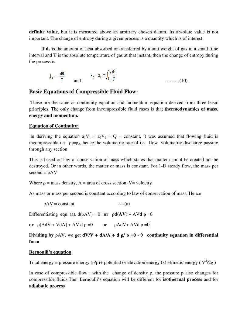
definite value, but it is measured above an arbitrary chosen datum. Its absolute value is not
important. The change of entropy during a given process is a quantity which is of interest.
If dθ is the amount of heat absorbed or transferred by a unit weight of gas in a small time
interval and T is the absolute temperature of gas at that instant, then the change of entropy during
the process is
and ………(10)
Basic Equations of Compressible Fluid Flow:
These are the same as continuity equation and momentum equation derived from three basic
principles. The only change from incompressible fluid cases is that thermodynamics of mass,
energy and momentum.
Equation of Continuity:
In deriving the equation a1V1 = a2V2 = Q = constant, it was assumed that flowing fluid is
incompressible i.e. ρ1=ρ2, hence the volumetric rate of i.e. flow volumetric discharge passing
through any section
This is based on law of conservation of mass which states that matter cannot be created nor be
destroyed. Or in other words, the matter or mass is constant. For 1-D steady flow, the mass per
second = ρAV
Where ρ = mass density, A = area of cross section, V= velocity
As mass or mass per second is constant according to law of conservation of mass, Hence
ρAV = constant ----(a)
Differentiating eqn. (a), d(ρAV) = 0 or ρd(AV) + AVd ρ =0
or ρ[AdV + VdA] + AV d ρ =0 or ρAdV+ AVd ρ =0
Dividing by ρAV, we get dV/V + dA/A + d ρ/ ρ =0 -� continuity equation in differential
form
Bernoulli’s equation
Total energy = pressure energy (p/ρ)+ potential or elevation energy (z) +kinetic energy ( V2/2g )
In case of compressible flow , with the change of density ρ, the pressure p also changes for
compressible fluids.The Bernoulli’s equation will be different for isothermal process and for
adiabatic process

(a) Bernoulli’s equation for Isothermal process:
For isothermal process, the relation between pressure(p) and density(ρ) is given by equation
p/ρ = constant
Finally, p/ρg logep + V2/2g + Z = constant
Bernoulli’s equation for compressible flow under going Isothermal process.
For the two points 1 and 2, this equation is written as
p1/ρ1g logep1 + V12/2g + Z1 = p2/ρ2g logep2 + V2
2/2g + Z2
(b) Bernoulli’s equation for Adiabatic (or Isentropic) Process:
For adiabatic process, the relation between pressure(p) and density(ρ) is given by equation
p/ρk = constant
Finally,
Bernoulli’s equation for compressible flow under going Isothermal process
For the two points 1 and 2, this equation is written as
Momentum Equations:
The momentum per second of a flowing fluid (momentum flux) Is equal to the product of mass
per second and the velocity of the flow.
Mathematically, the momentum per second of a flowing fluid ( compressible or incompressible )
is = ρAV x V, where ρAV = mass per second
The term ρAV is constant at every section of flow due to continuity equation. This means the
momentum per second at any section is equal to the product of a constant quantity and the
velocity. This also implies that momentum per second is independent of compressible effect.
Hence the momentum equation for incompressible and compressible fluid is the same. The
momentum
2
2
2
2
21
2
1
1
1
11ZV
g
p
k
kZV
g
p
k
k++
−=++
− ρρ
2
2
2
2
21
2
1
1
1
11ZV
g
p
k
kZV
g
p
k
k++
−=++
− ρρ
Equation for compressible fluid for any direction may be expressed as,
Net force in the direction of S
= rate of change of momentum in the direction of S
= Mass per second [ change of velocity]
= ρAV [V2 – V1]
where v2 = Final velocity in the direction of S
V1 = Initial velocity in the direction of S
Propagation of Disturbances in Fluid and Sonic Velocity of Flow:
Both solid and fluid as transmitting media consist of molecules with a difference that in case of a
solid the molecules are close together and in a fluid the molecules are relatively apart. Whenever
a minor disturbance takes place, it is transmitted through a solid body instantaneously, but in
case of fluid its molecules change in position before the disturbance is transmitted or propagated.
Thus the propagation of disturbance depends upon the elastic properties of a fluid. This
propagation of disturbance is similar to the propagation of sound through a media. The
speed of propagation of sound in a media is known as acoustic or sonic velocity which is due to
pressure difference. The sonic velocity is considered as an important factor in compressible
flow.
Derivation of sonic velocity:
Consider one-dimensional flow through a long straight cylinder made of rigid material and
having uniform thickness (refer Fig 2). Let a frictionless piston work in the cylinder with
velocity v. It compresses the fluid and produces disturbance propagating along its length in the
form of a pressure wave travelling with the velocity of sound C.
Let A = cross sectional area of the pipe
V = velocity of the piston
p = pressure of the fluid in pipe before movement of the
piston
ρ = Density of fluid before the movement of the piston

Fig 2. One dimensional pressure wave propagation
Let C = Velocity pressure wave or sound wave travelling in fluid
vdt = distance travelled by the piston in time dt
dp = Increase in pressure
Dρ =Increase in fluid density between piston and wave front
dt = A small interval of time with which piston is moved
Neglect friction and heat transfer, if any.
By applying momentum equation
……(a)
Now, ρVA = constant ….Equation of continuity
(neglecting terms of higher order)
i.e
or
(neglecting terms of higher order)

Therefore
Substituting the value of dv in eqn. (a)
Or ….....(b)
Equation (b) gives the velocity of sound wave which is the square root of the ratio of change of
pressure to the change of density of a fluid disturbance
Velocity of sound in terms of bulk modulus.
Bulk modulus k is defined as K = (Increase in pressure/(Decrease in volume/Original volume)
= dp/-(dvs/vs) …(c)
Where dvs = Decrease in volume,
vs= Original volume
Negative sign is taken as with the increase of pressure, volume decreases
Now we know mass of the fluid is constant. Hence ρ * volume = constant (since mass = ρ *
volume) ρ * vs= constant
Differentiating the above equation (ρ and vs are variables)
ρdvs+vsdρ = 0 or ρdvs= -vsdρ or dvs/vs= dp/ρ
substituting the value (-dvs/vs) in equation (c), we get K=dp/(dρ/ρ) = ρ(dp/dρ) or (dp/dρ) = (K/ρ)
the velocity of sound wave is given by
…..(d)
Equation (d) gives the velocity of sound wave in terms of bulk modulus and density. This
equation is applicable for liquids and gases.
ρd
dpC =
ρd
dpC =
ρ
K=

Velocity of sound for isothermal process
For isothermal process , p/ρ = constant
p ρ-1 = constant
Differentiating the above equation, we get
P(-1) ρ-2 dρ + ρ-1 dp = 0
Dividing by ρ-1 , we get –p ρ-1 dρ +dp or –p dρ + dp=0
dp = p/ρ dp or dp/dρ = p/ ρ= RT (as p/ρ = RT…Eqn. of state)
Substituting the value of dp/dρ in equation
We get
Velocity of sound for adiabatic (isentropic process)
p/ρk = constant
p ρ-k = constant
Differentiating the above equation, we get
P(-k) ρ-k-1 dρ + ρ-k dp = 0
Dividing by ρ-k , we get –pk ρ-1 dρ +dp or dp = pk/ρ dρ
dp/dρ = p/ρ k = RTk (as p/ρ = RT…Eqn. of state)
Substituting the value of dp/dρ in equation
We get …….(e)
Note 1. For the propagation of the minor disturbances through air, the process is assumed to be
adiabatic. The velocity of disturbances (pressure wave) through air is very high and hence there
is no time for any appreciable heat transfer.
2. isothermal process is considered for calculation of the velocity of the sound waves (or
pressure waves) only when it is given in the numerical problem that process is isothermal. If no
process is mentioned, it is assumed to be adiabatic.
ρd
dpC =
ρ
KC = RT=
ρd
dpC =
kRTc =

Mach number:
Mach number is defined as the square root of the inertia force of a flowing fluid to
the elastic force.Then,
Mach number =
Thus mach number = M [From Equation eqn. (d)]
Mach number, M = Velocity of fluid or body moving in fluid / Velocity of sound in the
fluid
If the Mach number of fluid flow is less than one(M<1), it is flowing with a velocity which is
less than velocity of sound.Such a flow is called subsonic flow. For M>1, the flow is known as
Supersonic flow. For M=1, the flow is sonic flow.
Problems on Mach number
1)Find the sonic velocity of the following fluid :
(i)Crude oil of specific gravity 0.8 and bulk modulus 153036 N/cm2
(ii)Mercury having a bulk modulus of 2648700 N/cm2
Solution:
Given:
(i) Crude oil: Specific gravity =0.8
Therefore density of oil, ρ =0.8 * 1000=800 kg/m3
Bulk modulus, K = 153036 N/cm2 = 153036 *104 N/m2
Using the equation for sonic velocity, as
C = √(k/ρ) = √((153036 *104)/800)
ceElasticfor
ceInertiaforM =
KA
AV2
ρ=
C
V
K
V
K
V===
ρρ
2
CK
=ρ
Q

= 1383.09 = 1383 m/s
(ii) Mercury: Bulk modulus, K= 2648700 N/cm2 = 2648700 * 104 N/m2
Specific gravity = 13.
Density of mercury, ρ =13.6 * 1000 =13600 kg/m3
The sonic velocity, C is : given by C = √(k/ρ)
= √((2648700 * 104)/13600)
= 1395.55 m/s
2) Find the sonic velocity for the following fluids:
(i) Crude oil of specific gravity 0.8 and bulk modulus 1.5 GN/m2
(ii) Mercury having a bulk modulus of 27 GN/m2
Solution:
Crude oil: Specific gravity =0.8
Therefore density of oil, ρ =0.8 * 1000 =800 kg/m3
Bulk modulus, K = 1.5 GN/m2
Mercury: Bulk modulus, K= 27 GN/m2
Density of mercury, ρ =13.6 * 1000 =13600 kg/m3
Sonic velocity, Coil , CHg :
Sonic velocity is given by the relation :
C = √(k/ρ)
Coil = √((1.5 *109)/800) = 1369.3 m/s
CHg = √((27 *109)/13600) = 1409 m/s
3) Find the speed of the sound wave in air at sea-level where the pressure and temperature are
10.1043 N/cm2 (absolute) and 15oC respectively. Take R =287 J/kg K and k=1.4.

Solution: Given :
Pressure, p =10.1043 N/cm2
= 10.1043 * 104 N/m2
Temperature, t = 15oC
Therefore T = 273+15 = 288 K
R = 287 J/kg K, k=1.4.
For adiabatic process, the velocity of sound is given by
C=√(kRT) = √(1.4 * 287 *288)
= 340.17 m/s
4) Calculate the Mach number at a point on a jet propelled aircraft, which is flying at 1100
km/hour at sea level where air temperature is 20oC. Take k = 1.4 and R = 287 J/kg K.
Solution: Given :
Speed of aircraft,V = 1100 km/hour
= (1100 * 1000)/(60 * 60) = 305.55 m/s
Temperature, t = 20oC
Therefore T = 273+20 = 293 K
k = 1.4, R = 287 J/kg K.
The velocity of sound is given by the equation
C = √(kRT)
= √(1.4 * 287 *293)
= 343.11 m/s
Mach number is given as
M = (V/C) = (305.55/343.11) = 0.89

5) An aero plane is flying at an height of 14 km where the temperature is -50ºC. The speed of the
is corresponding to M = 2.0. Assuming k = 1.4 and R = 287 k/kg K, find the speed of the plane
Solution:
Height of plane, Z = 15 km(extra data)
Temperature, t = -50oC
Therefore, T = -50+273 = 223oC
Mach number, M = 2.0, k = 1.4, R=287 j/kg K
Using equation, we get the velocity of sound as C = √(kRT)
We have Mach number M = V/C
2.0= V/299.33
V = 2.0 x 299.33 = 598.66 m/s
= 598.66 x 60x60/1000 = 2155.17 km/hr
6)Find the Mach number of rocket travelling in standard air with a Speed of 1600 km/hr.
Solution:
Same in MKS and SI units
Standard air has the following values at sea level;
sm /33.2992232874.1 =××=

Nature of propagation of pressure Waves or disturbances) in a compressible Fluid
Whenever any disturbance is produced in a compressible fluid, the disturbance is propagated in
all direction with a Velocity of sound. The nature of propagation of the disturbance depends
upon the Mach number. Let a projectile travel in a straight line with a steady velocity V. It will
produce disturbance propagating in all directions.
With point 3 as center, draw a circle with radius C∆ t, and with point 2 as center, draw another
circle with radius 2c∆t. similarly with point A as center draw circle with radius to 4c ∆t. From
this it will be seen that point B remains within the sphere of radius 4c
Figure 3. Nature of disturbances in compressible flow

(a) M<1, when V is less than the velocity of sound C,which means the projectile lags behind
the pressure wave.
(b) M=1 Since V=C, then circles drawn join to points as shown in Fig 1.2(b). The circle
drawn with center A will pass through B.
(c) M>1, i.e V>C, then the sphere of propagation of disturbance is smaller and the velocity
of projectile is higher.
Drawing the circles as earlier, if tangents are drawn to the circles, the spherical pressure waves
form a cone with its vertex at B. It is known as Mach cone. Half cone angle is known as mach
angle and denoted by and
In such a case the disturbance takes place inside the coneand outside it there is no disturbance
which is then called Silence zone. It is seen that when an aero plane is moving with supersonic
speed, the noise of the plane is heard only after the plane has already passed over us.
When M >1, the effect of the disturbance is felt only in the region Inside the mach cone. This
region is called the zone of action
Stagnation Properties:
When the fluid flowing past an immersed body, and at a point on the body if the resultant
velocity becomes zero, the value of pressure, temperature and density at that point are called
Stagnation point. The values of pressure, temperature and density are called stagnation
pressure, stagnation temperature and stagnation density respectively. They are denoted as ps,
ρs and Ts respectively.
Expression for stagnation pressure (ps)
Consider a compressible fluid flowing past an immersed body under frictionless adiabatic
conditions.
Consider points 1 and 2 on a stream line.
Let p1 = pressure of compressible fluid at point 1
V1 = Velocity of fluid at 1 and
ρ1= Density of fluid at 1
p1, v2 ρ2 = corresponding values of pressure, velocity and density at point 2
By applying Bernoulli’s equation for adiabatic flow by equation at 1 and 2, we get
2
2
2
2
21
2
1
1
1
11ZV
g
p
k
kZV
g
p
k
k++
−=++
− ρρ

Finally
Where Ps =stagnation pressure
Expression for stagnation Density (ρs )
ps/ ρs = RTs
Expression for stagnation (Ts)
Equation fo state is given by ps/ρs= RT
Finally
1) A projectile is travelling in air having pressure and temperature as 88.3 kN/m2 and -2oC. If
the Mach angle is 40o, find the velocity of the projectile. Take k =1.4 and R = 287 J/kg K.
Solution:
Pressure, p= 88.3 kN/m2
Temperature of air, t= -2ºC
T = -2+273 = 271K
Mach angle, α = 40o
k =1.4, R = 287 J/kg K.
L et Velocity of the projectile = V
Sonic velocity, C = √( kRT)
= √(1.4*287 *271)
= 330 m/s
Now, sinα= C/V
−
−+=
12
112
11
k
k
s Mk
pp
−+=
2
112
11 M
kTTs

or sin 40o=330/V
or V= 330/sin40o
V = 513.4 m/s
2) A projectile travels in air of pressure 10.1043 N/cm2 at 10oC at a speed of 1500 km/hour. Find
the Mach number and the Mach angle. Take k = 1.4 and R = 287 J/kg K.
Solution:
Given :
Pressure, p = 10.1043 N/cm2
= 10.1043 * 104 N/m2
Temperature, t = 10oC
T = 10+273 = 283 K
Speed of projectile, V=1500 km/hour
= (1500 * 1000)/(60 * 60) m/s
= 416.67 m/s
k = 1.4, R = 287 J/kg K.
For adiabatic process velocity of sound C is given by
C = √(kRT)
= √(1.4 * 287 *283)
= 337.20 m/s
Therefore Mach number, M = (V/C)
= (416.67/337.20)
= 1.235.
Therefore Mach angle is obtained as
sinα = (C/V)

= (1/M)
= (1/1.235)
= 0.8097
Therefore Mach angle, α = sin-1(0.8097)
= 54.06o
3) Find the velocity of bullet fired in standard air if the Mach angle is 30o. Take R = 287.14 J/kg
k and k = 1.4 for air. Assume temperature as 15oc.
Solution:
Given :
Mach angle α = 30o
R = 287.14 J/kg k
k = 1.4
Temperature, t = 15oC
Therefore T = 15 + 273 = 288 k
Velocity of sound is given as
C = √(kRT)
= √(1.4 * 287.14 * 288)
= 340.25 m/s
Using the relation, sin α = C/V
sin 30o = 340.25/V
V = 340.25/sin 30
= 680.5 m/s

4)An air plane is flying at an altitude of 15 km where the temperature is -50oC. The speed of the
plane corresponds to Mach number of 1.6. Assuming k= 1.4 and R = 287 J/kg K for air. Find
the speed of the plane and Mach angle α.
Solution:
Given :
Height of plane, H = 15 km = 15 * 1000 = 15000 m
Temperature, t = -50oC
therefore T = -50+273 = 223 K
Mach number, M = 1.6, k=1.4 and R = 287 J/kg K
Find : (i) speed of plane (V)
(ii) Mach angle, α
Velocity of sound wave is given as
C = √(kRT) = √(1.4 * 287 * 223) = 229.33 m/s
(ii) Mach angle, α
Using the relation for Mach angle, we get
sin α = C/V = 1/(V/C) =1/M = 1/1.6 = 0.625
α = sin-1 0.625 = 38.68o
(i) Speed of plane, V
We know, M=V/C
1.6 = V/299.33
V = 1.6 * 299.33 = 478.928 m/s
= (478.98 * 3600)/1000 = 1724.14 m/s

5)Find the Mach number when an aeroplane is flying at 1100 km/hour through still air having a
pressure of 7 N/cm2 and temperature -5oC. Wind velocity may be taken as zero. Take R = 287.14
J/kg K. calculate the pressure, temperature and density of air at stagnation point on the
nose of the plane. Take k=1.4.
Solution:
Given :
Speed of aeroplane, V=1100 km/hour
= (1100 * 1000)/(60 *60)
= 305.55 m/s
Pressure of air, p1=7 N/cm2 = 7*104 N/m2
Temperature, t1 = -5oC
Therefore T1 = -5 +273 = 268 K
R = 287.14 J/kg K
K=1.4
Using relation C = √(kRT) for velocity of sound for adiabatic process, we have
C1 = √(1.4 *287.14 *268) = 328.2 m/s
Therefore Mach number, M1 = (V1/C1)
= (305.55/328.20) = 0.9309 = 0.931
Stagnation pressure, ps. using equation for stagnation pressure,
ps= p1[1+((k-1)/2)M12]k/(k-1)
= 7.0 *104[1+((1.4-1)/2)(0.931)2]1.4/(1.4-1)
= 7.0 *104[1+0.1733]1.4/0.4
= 7.0 *104[1.1733]3.5 = 12.24 * 104 N/m2
= 12.24 N/cm2
Stagnation temperature, Ts. using the equation for stagnation temperature,

Ts = T1[1+((k-1)/2) M12]
= 268 [1+((1.4-1)/2) (0.931)2]
= 268 [1.1733] = 314.44 k
Therefore
ts = Ts – 273 = 314.44 – 273 = 41.44 oC
Stagnation density , ρs. Using equation of state for stagnation density, ps/ρs = RTs
ρs = ps/(RTs)
In the above equation given, if R is taken as 287.14 J/kg K, then pressure should be taken in
N/m2 so that the value of ρ is in kg/m3. Hence ps = 12.24 *104 N/m2 and Ts = 314.44 k.
ρs = 12.24 *104/(287.14 * 314.44) = 1.355 kg/m3
6) Calculate the stagnation pressure, temperature, density on the stagnation point on the nose of a
plane, which is flying at 800 km/hour through still air having a pressure 8.0 N/cm2 (abs.) and
temperature -10 0C.Take R=287 J/Kg K and k = 1.4.
Solution:
Given:
Speed of plane, V = 800 km/hour
= (800*1000)/(60*60) = 222.22 m/s
Pressure of air, p1 = 8.0 N/cm2 = 8.0*104 N/cm2
Temperature, t1 = -10 0C
T1 = -10 + 273 = 2630 C
R= 287 J/Kg0 K
k = 1.4
For adiabatic flow, the velocity of sound is given by
C = √(KRT)
= √(1.4*287*263)

=325.07 m/s.
Mach number, M = V/C
= 222.22/325.07 =0.683
This Mach number is the local Mach number and hence equal to M1.
Therefore M1 = 0.683
Using equation for stagnation pressure,
ps = p1 [1+ ((k-1)/2) M12] (k/(k-1))
= 8.0*104[1+((1.4-1.0)/2.0)*(0.683)2](1.4/(1.4-1.0))
=8.0*104[1.0933]3.5 = 10.93*104 N/m2
= 10.93 N/cm2
Using equation for stagnation temperature
Ts = T1 [1+ ((k-1)/2) M12] =263 [1+ ((1.4-1.0)/2.0)*(0.683)2]
=263 [1.0933] =287.5 K
Therefore ts = TS - 273 =287.5 – 723
=14.5 0C
Using equation of state, p/ρ = RT
For stagnation point, ps /ρs=RTS
Therefore ρs= ps / RTS
As R =287 J/Kg K, the value of ps should be taken in N/m2 so that the value of ρs is obtained in
Kg/m3.
ps =10.93*104 N/m2
Therefore Stagnation density,
ρs = (10.93*104) / (287*287.5)
= 1.324 Kg/m3

Area-velocity Relationship for Compressible Flow:
The are velocity relation ship for incompressible fluid is given by the continuity equation as A *
V = constant
From the above equation, it is clear that with the increase of area, velocity decreases. But in case
of compressible fluid, the continuity equation is given by, ρAV = constant ……(i)
Differentiating equation(i), we get
ρd(AV) + Avdρ = 0 or ρ[AdV + VdA] + Avdρ =0
or ρAdV + ρVdA + Avdρ =0
Dividing by ρAV, we get dV/V + dA/A + dρ/ρ =0 …..(ii)
The Euler’s equation for compressible fluid is given by equation, as dp/ρ + VdV +gdZ =0
Neglecting the Z term, the above equation is written as
dp/ρ +VdV =0
This equation can also be written as
dp/ρ x dρ/dρ + VdV = 0
(Dividing and multiplying by dρ)
or dp/dρ x dρ/ρ + VdV = 0
But dp/dρ = C2
Hence above equation becomes as C2 dρ/ρ + VdV = 0
or C2 dρ/ρ = -VdV
or dρ/ρ = VdV/C2
Substituting the value of dρ/ρ in equation (ii), we get
dV/V + dA/A - VdV/C2 = 0
or dA/A = VdV/C2 - dV/V = dV/V[V2/C2 -1]
dA/A = dV/V[M2-1]

Comparison of flow properties in subsonic and supersonic nozzles and diffusers
Pitot-static tube in a compressible flow
The pitot - static tube, when used for determining the velocity at any point in a compressible
fluid, gives only the difference between the stagnation head and static head. From this difference,
the velocity of the incompressible fluid at that point is obtained from the relation
V = √(2gh) , where h = difference in two heads.
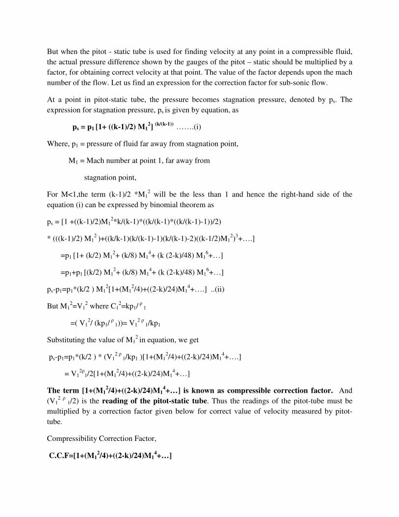
But when the pitot - static tube is used for finding velocity at any point in a compressible fluid,
the actual pressure difference shown by the gauges of the pitot – static should be multiplied by a
factor, for obtaining correct velocity at that point. The value of the factor depends upon the mach
number of the flow. Let us find an expression for the correction factor for sub-sonic flow.
At a point in pitot-static tube, the pressure becomes stagnation pressure, denoted by ps. The
expression for stagnation pressure, ps is given by equation, as
ps = p1 [1+ ((k-1)/2) M12] (k/(k-1)) …….(i)
Where, p1 = pressure of fluid far away from stagnation point,
M1 = Mach number at point 1, far away from
stagnation point,
For M<1,the term (k-1)/2 *M12 will be the less than 1 and hence the right-hand side of the
equation (i) can be expressed by binomial theorem as
ps = [1 +((k-1)/2)M12*k/(k-1)*((k/(k-1)*((k/(k-1)-1))/2)
* (((k-1)/2) M12 )+((k/k-1)(k/(k-1)-1)(k/(k-1)-2)((k-1/2)M1
2)3+….]
=p1 [1+ (k/2) M12+ (k/8) M1
4+ (k (2-k)/48) M16+…]
=p1+p1 [(k/2) M12+ (k/8) M1
4+ (k (2-k)/48) M16+…]
ps-p1=p1*(k/2 ) M12[1+(M1
2/4)+((2-k)/24)M14+….] ..(ii)
But M12=V1
2 where C12=kp1/
ρ 1
=( V12/ (kp1/
ρ 1))= V1
2 ρ 1/kp1
Substituting the value of M12 in equation, we get
ps-p1=p1*(k/2 ) * (V12 ρ
1/kp1 )[1+(M12/4)+((2-k)/24)M1
4+….]
= V12ρ
1/2[1+(M12/4)+((2-k)/24)M1
4+…]
The term [1+(M12/4)+((2-k)/24)M1
4+…] is known as compressible correction factor. And
(V12 ρ
1/2) is the reading of the pitot-static tube. Thus the readings of the pitot-tube must be
multiplied by a correction factor given below for correct value of velocity measured by pitot-
tube.
Compressibility Correction Factor,
C.C.F=[1+(M12/4)+((2-k)/24)M1
4+…]

1) Calculate the numerical factor by which the actual pressure difference shown by the gauge of
a pitot-static tube must be multiplied to allow for compressibility when the value of the Mach
number is 0.9. Take k=1.4
Solution :
Mach number, M1 = 0.9
K = 1.4
Using equation for, Compressibility Correction Factor is
C.C.F =[ 1+(M12/4)+((2-k)/24)M1
4+…] =1+((0.92)/4)+((21.4)/24)(0.9)4 +….
=1.0+0.2025+0.0164+…. = 1.2189.
Numerical factor by which the actual pressure difference is to be multiplied = 1.2189
=============@@@@@@@@@@@@@@====================