fluid flow switch model q-1 - harwilharwil.com/wp-content/uploads/2011/04/flow.pdf · • oil...
TRANSCRIPT

Detects and Signals Flow Change
Typical Working Fluids
Typical Uses: Monitoring flow of coolant water and fluids supplied to:
In Chemical Processing
• Superior Long Term Performance• Continuous Adjustment While Operating • 6 Interchangeable orifices plus 2:1 continuous switch adj.
each orifice. • Line Pressure to 300 psig• Temperature 180°F Continuous• Calibrated Independent of Line Pressure and Temperature
• Maintains Calibration Limits when Subjected to Reasonable Line Hydraulic Hammer or Surge Pulses
• SPDT 15 amp switching capacity model or Dry Circuit Computer/PLC Interface model
• Intrinsically Safe Relay Allows Model Q-1 to be used in Hazardous Areas. (see page 46)
• Maintenance and checkout is a snap for your present personnel using an uncomplicated standard test meter.
Non-Magnetic
Fluid Flow Switch Model Q-10.12 to 8.0 GPM
• Fluid Blending Systems • Heat Transfer Fluids • Liquid Scrubbers • Liquid Transfer• Monitor Filter Clogging
• On/Off Control of Chemical Feed Pumps
• Starting Back-up Pumps • Water Treatment
541 Kinetic Drive, Oxnard, CA 93030Tel (805) 988-6800 Fax (805) 988-6804
Email. [email protected]
Limited Warranty Page 7
• Alcohols• Contaminated Ground Water• Filtered Sewage Water• Glycols• Oils
• Pure Water• Seawater• Soap Solutions• Tap Water
• Air Condition Systems • Brakes and Clutches• Computer Systems • Diffusion Vacuum Pumps • Diodes, SCRs, Triacs, etc. • Electro Magnets • High Power Transistors • Marine and Stationary
Engines
• Oil Supplied to Large Bearing and Gear Systems
• Plastic Molding Equipment • RF and Radar Transmitter• Spot welders• Transformers • Vacuum Systems
MOUNT INANY POSITION
TURBULENT FLOWREDUCTION
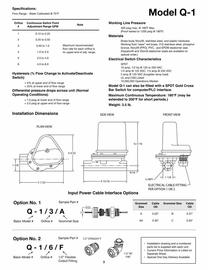
Model Q-1Specifications:Flow Range - Water Calibrated @ 70°F
Orifice #
Continuous Switch Point Adjustment Range GPM Note
1 0.12 to 0.25
Maximum recommended flow rate for each orifice is 4x upper-end of adj. range.
2 0.25 to 0.50
Maximum recommended flow rate for each orifice is 4x upper-end of adj. range.
3 0.50 to 1.0 Maximum recommended flow rate for each orifice is 4x upper-end of adj. range.4 1.0 to 2.0
Maximum recommended flow rate for each orifice is 4x upper-end of adj. range.
5 2.0 to 4.0
Maximum recommended flow rate for each orifice is 4x upper-end of adj. range.
6 4.0 to 8.0
Maximum recommended flow rate for each orifice is 4x upper-end of adj. range.
Hysteresis (% Flow Change to Activate/Deactivate Switch) ≈ 5% at upper end of flow range ≈ 25% at lower end of flow range
Differential pressure drops across unit (Normal Operating Conditions) ≈ 1.0 psig at lower end of flow range ≈ 5.0 psig at upper end of flow range
Working Line Pressure 300 psig max. @ 180˚F Max (Proof tested to 1200 psig @ 180˚F)
Materials Brass body Noryl®, stainless steel, and plastic hardware. Working fluid “sees” red brass, 316 stainless steel, phosphor bronze, Noryl® (PPO), PVC, and EPDM elastomer seal. (Hypalon® and Viton® elastomer seals are available on special order.)
Electrical Switch Characteristics SPDT 15 amp, 1/2 hp @ 125 or 250 VAC 1/2 amp @ 125 VDC, 1/4 amp @ 250 VDC 5 amp @ 125 VAC (tungsten lamp load) UL and CSA Listed 10,000,000 Operations Median
Model Q-1 can also be fitted with a SPDT Gold Cross Bar Switch for computer/PLC interface.Maximum Continuous Temperature: 180°F (may be extended to 200°F for short periods.)Weight: 3.5 lb.
9
• Installation drawing and a numbered parts list is supplied with each unit.
• Current Price Information is Listed on Separate Sheet.
• Special One Day Delivery Available.
Installation Dimensions
Input Power Cable Interface Options
Grommet Size
Cable OD
Grommet Size Cable OD
A 0.25” B 0.37”
AA 0.30” C 0.50”
O.D.
1/2” STRAIGHT F
1/2” 90˚F90˚

Detects and Signals Flow Change
Typical Working Fluids
Typical Uses: Monitoring flow of coolant water and fluids supplied to:
In Chemical Processing
• Superior Long Term Performance• Line Pressure to 300 Psig• Continuous Adjustment While Operating• Temperature 180°F Continuous• Four individual Drag Disk options plus continuous adjustment
provides wide operating range• For use in particle contaminated fluids
• SPDT 15 amp switching capacity model or Dry Circuit Computer/PLC Interface model
• Intrinsically Safe Relay Allows Model Q-4E to be used in Hazardous Areas (see page 46).
• Maintains Calibration Limits When Subjected to Reasonable Line Hydraulic Hammer or Surge Pulses
• Maintenance and checkout is a snap for your present personnel using an uncomplicated standard test meter.
Fluid Flow Switch Model Q-4E4 to 70 GPM
541 Kinetic Drive, Oxnard, CA 93030Tel (805) 988-6800 Fax (805) 988-6804
Email. [email protected]
• Contaminated Groundwater• Fire Sprinkler Flow Alarms• Fluid Blending Systems• Heat Transfer Fluids• Liquid Scrubbers• Liquid Transfer
• Monitor Filter Clogging• On/Off Control of Chemical
Feed Pumps• Starting Back-up Pumps• Water Treatment
Non-Magnetic
10
Limited Warranty Page 7
• Alcohols• Glycols• Hydrocarbons• Oils
• Pure Water• Sea Water• Sewage• Soap Solutions
• Tap Water• Waste Water
MODEL Q-4E/1(USES ORIFICE &
DRAG DISK)
MODELS Q-4E/2, 3 & 4(USE DRAG DISK ONLY)
MOUNT INANY POSITION
TURBULENT FLOWREDUCTION
• Air Condition Systems• Brakes and Clutches• Computer Systems• Diffusion Vacuum Pumps• Diodes, SCR's, Triacs, etc.• Electro Magnets• Fluids for Ceramic Cutting &
Grinding Wheels• Grinding and Polishing Fluids• High Power Transistors• Marine & Stationary Engines
• Plastic Molding Equipment• Pressurized Oil for Floating
Bearings & Ways• Refrigeration Systems• RF and Radar Transmitter• Spot welders• Transformers• Vacuum Systems• Water & Oil Based Cutting
Fluids

Model Q-4ESpecifications:Flow Range - Water Calibrated @ 70°F
Model # Continuous Switch Point Adjustment Range GPM Note
Q-4E/1 4–8 Orifice/Drag Disk
Q-4E/2 6–20 Drag Disk Only
Q-4E/3 15–35 Drag Disk Only
Q-4E/4 25–70 Drag Disk Only
Hysteresis (% Flow Change to Activate/Deactivate Switch) ≈ 5% at upper end of flow range ≈ 25% at lower end of flow range
Differential pressure drops across unit (Normal Operating Conditions) ≈ 1.0 psig at lower end of flow range ≈ 5.0 psig at upper end of flow range
Working Line Pressure 300 psig max. @ 180˚F Max (Proof tested to 1200 psig @ 180˚F)
Materials Brass body, Noryl®, stainless steel, and plastic hardware. Working fluid “sees” red brass, 316 stainless steel, phosphor bronze and EPDM elastomer seal. (Hypalon® and Viton® Elastomer Seals are available on special order.)
Electrical Switch Characteristics SPDT 15 amp, 1/2 hp @ 125 or 250 VAC 1/2 amp @ 125 VDC, 1/4 amp @ 250 VDC 5 amp @ 125 VAC (tungsten lamp load) UL and CSA Listed 10,000,000 Operations Median
Model Q-4E can also be fitted with a SPDT Gold Cross Bar Switch for computer/PLC interface.Maximum Continuous Temperature: 180°F (may be extended to 200°F for short periods.)Weight: 5 lb.
11
Installation Dimensions
• Installation drawing and a numbered parts list is supplied with each unit.
• Current Price Information is Listed on Separate Sheet.
• Special One Day Delivery Available.
Input Power Cable Interface Options
Grommet Size
Cable OD
Grommet Size Cable OD
A 0.25” B 0.37”
AA 0.30” C 0.50”
O.D.
1/2” STRAIGHT F
1/2” 90˚F90˚
Grommet Size
Option No. 1Basic Model #
Sample Part #
Orifice/Drag Disk #
Q - 4E / 1 / B
½” Flexible Conduit Fitting
Option No. 2Basic Model #
Sample Part #
Orifice/Drag Disk #
Q - 4E / 3 / F
Detects and Signals Flow Change
Typical Working Fluids
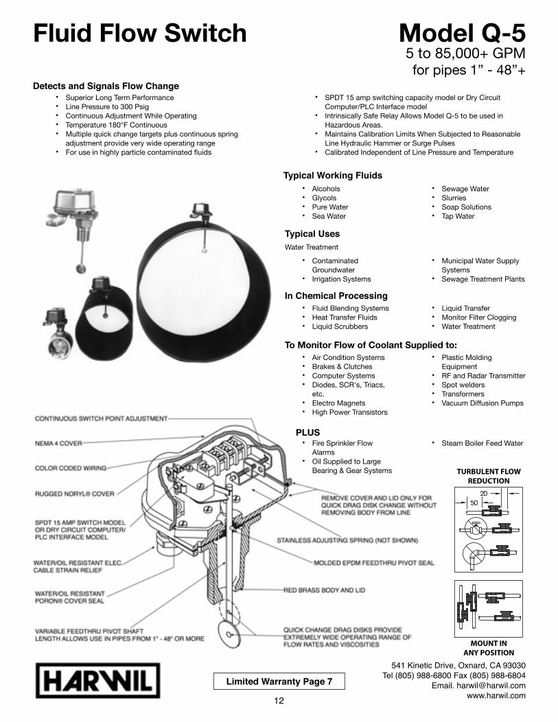
! ! !Typical UsesWater Treatment
In Chemical Processing
To Monitor Flow of Coolant Supplied to:
PLUS
Fluid Flow Switch Model Q-55 to 85,000+ GPMfor pipes 1” - 48”+
• Fluid Blending Systems• Heat Transfer Fluids• Liquid Scrubbers
• Liquid Transfer• Monitor Filter Clogging• Water Treatment
• Air Condition Systems• Brakes & Clutches• Computer Systems• Diodes, SCR's, Triacs,
etc.• Electro Magnets• High Power Transistors
• Plastic Molding Equipment
• RF and Radar Transmitter• Spot welders• Transformers• Vacuum Diffusion Pumps
• Fire Sprinkler Flow Alarms
• Oil Supplied to Large Bearing & Gear Systems
• Steam Boiler Feed Water
541 Kinetic Drive, Oxnard, CA 93030Tel (805) 988-6800 Fax (805) 988-6804
Email. [email protected]
• Contaminated Groundwater
• Irrigation Systems
• Municipal Water Supply Systems
• Sewage Treatment Plants
• Alcohols• Glycols• Pure Water• Sea Water
• Sewage Water• Slurries• Soap Solutions• Tap Water
12
• Superior Long Term Performance• Line Pressure to 300 Psig• Continuous Adjustment While Operating• Temperature 180°F Continuous• Multiple quick change targets plus continuous spring
adjustment provide very wide operating range• For use in highly particle contaminated fluids
• SPDT 15 amp switching capacity model or Dry Circuit Computer/PLC Interface model
• Intrinsically Safe Relay Allows Model Q-5 to be used in Hazardous Areas.
• Maintains Calibration Limits When Subjected to Reasonable Line Hydraulic Hammer or Surge Pulses
• Calibrated Independent of Line Pressure and Temperature
Limited Warranty Page 7
MOUNT INANY POSITION
TURBULENT FLOWREDUCTION
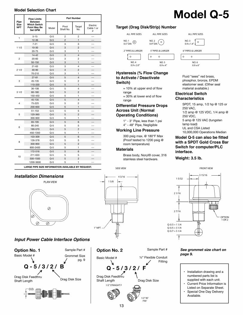
Model Q-5Model Selection Chart
Pipe Size NPT
Flow Limits Between
Which Switch Point May Be
Set GPM
Part NumberPart NumberPart NumberPart NumberPipe Size NPT
Flow Limits Between
Which Switch Point May Be
Set GPMModel Pivot
Shaft No.Target
No.Electric
Cable 1 or 2
15-15 Q-5 2 2 ---
112-36 Q-5 2 1 ---
1 1/2
7-21 Q-5 3 3 ---
1 1/2 10-30 Q-5 3 2 ---1 1/2
20-75 Q-5 3 1 ---
2
14-42 Q-5 3 4 ---
2 20-60 Q-5 3 2 ---2
50-150 Q-5 3 1 ---
2 1/2
21-63 Q-5 3 4 ---
2 1/2 30-90 Q-5 3 2 ---2 1/2
70-210 Q-5 3 1 ---
3
27-81 Q-5 5 4 ---
3 45-135 Q-5 5 2 ---3
110-330 Q-5 5 1 ---
3 1/2
36-108 Q-5 5 4 ---
3 1/2 60-180 Q-5 5 2 ---3 1/2
150-450 Q-5 5 1 ---
4
45-135 Q-5 5 4 ---
4 75-225 Q-5 5 2 ---4
200-600 Q-5 5 1 ---
5
51-153 Q-5 5 5 ---
5 120-360 Q-5 5 2 ---5
300-900 Q-5 5 1 ---
6
65-195 Q-5 5 6 ---
680-240 Q-5 5 5 ---
6190-570 Q-5 5 2 ---
6
450-1350 Q-5 5 1 ---
8
103-309 Q-5 5 6 ---
8126-378 Q-5 5 5 ---
8300-900 Q-5 5 2 ---
8
800-2400 Q-5 5 1 ---
10
172-516 Q-5 5 6 ---
10211-633 Q-5 5 5 ---
10500-1500 Q-5 5 2 ---
10
1200-3600 Q-5 5 1 ---
LARGE PIPE SIZE INFORMATION AVAILABLE BY REQUEST.LARGE PIPE SIZE INFORMATION AVAILABLE BY REQUEST.LARGE PIPE SIZE INFORMATION AVAILABLE BY REQUEST.LARGE PIPE SIZE INFORMATION AVAILABLE BY REQUEST.LARGE PIPE SIZE INFORMATION AVAILABLE BY REQUEST.LARGE PIPE SIZE INFORMATION AVAILABLE BY REQUEST.
13
Hysteresis (% Flow Change to Activate / Deactivate Switch)
≈ 10% at upper end of flow range≈ 30% at lower end of flow range
Differential Pressure Drops Across Unit (Normal Operating Conditions)
1" - 3" Pipe, less than 1 psi4" - 48" Pipe, Negligible
Working Line Pressure300 psig max. @ 180°F Max(Proof tested to 1200 psig @ room temperature)
MaterialsBrass body, Noryl® cover, 316 stainless steel hardware.
Fluid “sees” red brass, phosphor, bronze, EPDM elastomer seal. (Other seal material available.)
Electrical Switch Characteristics
SPDT, 15 amp, 1/2 hp @ 125 or 250 VAC,1/2 amp @ 125 VDC, 1/4 amp @ 250 VDC,5 amp @ 125 VAC (tungsten lamp load)UL and CSA Listed10,000,000 Operations Median
Model Q-5 can also be fitted with a SPDT Gold Cross Bar Switch for computer/PLC interface.Weight: 3.5 lb.
ALL PIPE SIZES ALL PIPE SIZES ALL PIPE SIZES
NO. 40.9 x 2.0”
NO. 50.9 x 4”
NO. 60.9 x 6”
2” PIPES & LARGER 5” PIPES & LARGER 6” PIPES & LARGER
NO. 10.5” DIA
NO. 20.9” DIA
NO. 30.9 x 1.4”
Target (Drag Disk/Strip) Number
PLAN VIEW
1" NPT
4 3/16
SIDE VIEW
1 5/8
OPTION1 OR 2
Q-5/3 = 1 1/4Q-5/5 = 3 1/4Q-5/7 = 5 1/4
2 1/16
FRONT VIEW
2 7/16
3 15/161 5/32
Installation Dimensions
Q - 5 / 3 / 2 / B
Basic Model #
Drag Disk Size
• Installation drawing and a numbered parts list is supplied with each unit.
• Current Price Information is Listed on Separate Sheet.
• Special One Day Delivery Available.
Input Power Cable Interface Options
O.D.1/2” STRAIGHT F
1/2” 90˚F90˚
Grommet Sizepg. 9
Option No. 1Basic Model #
Sample Part #
Drag Disk SizeDrag Disk Feedthru Shaft Length
½” Flexible Conduit Fitting
Option No. 2 Sample Part #
Drag Disk Feedthru Shaft Length
Q - 5 / 3 / 2 / F
See grommet size chart on page 9.
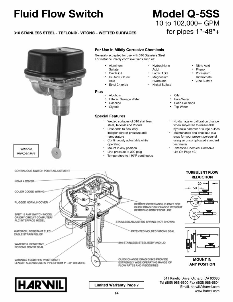
316 STAINLESS STEEL - TEFLON® - VITON® - WETTED SURFACES
For Use in Mildly Corrosive ChemicalsGenerally accepted for use with 316 Stainless SteelFor instance, mildly corrosive fluids such as:
Plus
Special Features
Fluid Flow Switch Model Q-5SS10 to 102,000+ GPM
for pipes 1”-48”+
• Aluminum Sulfate
• Crude Oil• Diluted Sulfuric
Acid • Ethyl Chloride
• Hydrochloric Acid
• Lactic Acid• Magnesium
Hydroxide• Nickel Sulfate
• Nitric Acid• Phenol• Potassium
Dichromate• Zinc Sulfate
• Alcohols• Filtered Sewage Water• Gasoline• Glycols
• Oils• Pure Water• Soap Solutions• Tap Water
541 Kinetic Drive, Oxnard, CA 93030Tel (805) 988-6800 Fax (805) 988-6804
Email. [email protected]
• Wetted surfaces of 316 stainless steel, Teflon® and Viton®
• Responds to flow only, independent of pressure and temperature
• Continuously adjustable while operating
• Mount in any position• Line pressure to 300 psig• Temperature to 180°F continuous
• No damage or calibration change when subjected to reasonable hydraulic hammer or surge pulses
• Maintenance and checkout is a snap for your present personnel using an uncomplicated standard test meter
• Extensive Chemical Corrosive List On Page 49.
14
Limited Warranty Page 7
MOUNT INANY POSITION
TURBULENT FLOWREDUCTION
Reliable, Inexpensive
Q - 5SS / 3 / 2 / B
Basic Model #
Drag Disk Size
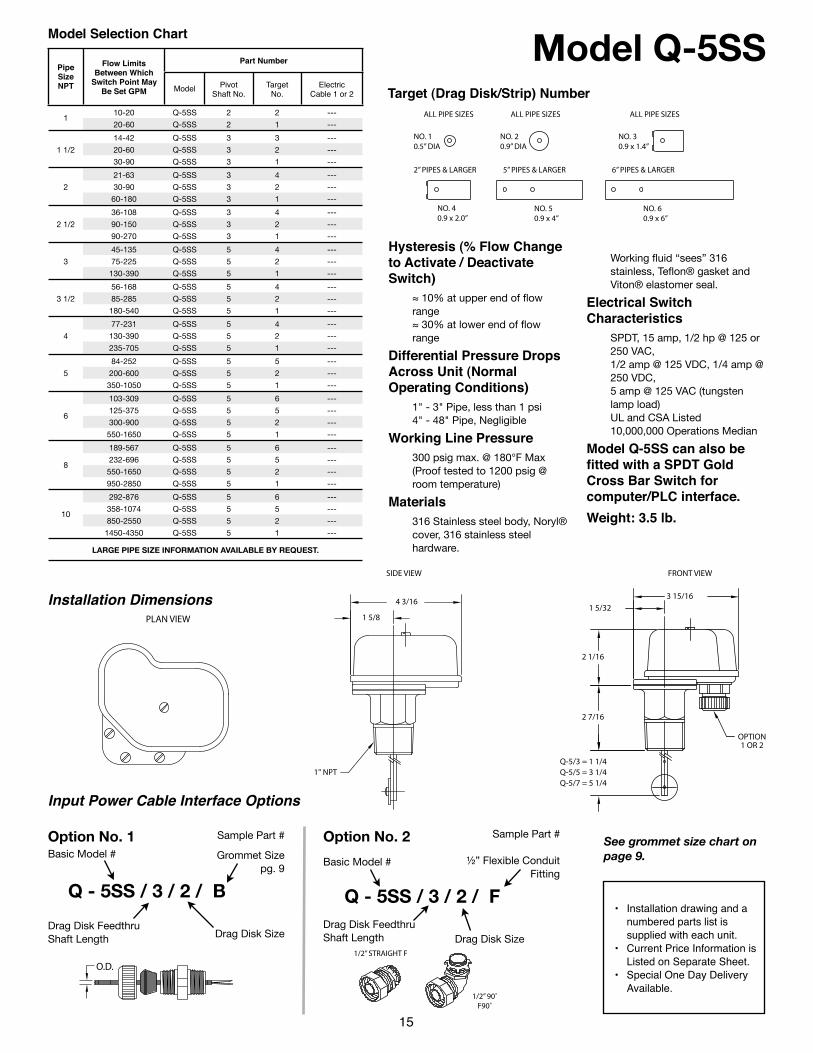
Model Q-5SSModel Selection Chart
Pipe Size NPT
Flow Limits Between Which
Switch Point May Be Set GPM
Part NumberPart NumberPart NumberPart NumberPipe Size NPT
Flow Limits Between Which
Switch Point May Be Set GPM Model Pivot
Shaft No.Target
No.Electric
Cable 1 or 2
110-20 Q-5SS 2 2 ---
120-60 Q-5SS 2 1 ---
1 1/2
14-42 Q-5SS 3 3 ---
1 1/2 20-60 Q-5SS 3 2 ---1 1/2
30-90 Q-5SS 3 1 ---
2
21-63 Q-5SS 3 4 ---
2 30-90 Q-5SS 3 2 ---2
60-180 Q-5SS 3 1 ---
2 1/2
36-108 Q-5SS 3 4 ---
2 1/2 90-150 Q-5SS 3 2 ---2 1/2
90-270 Q-5SS 3 1 ---
3
45-135 Q-5SS 5 4 ---
3 75-225 Q-5SS 5 2 ---3
130-390 Q-5SS 5 1 ---
3 1/2
56-168 Q-5SS 5 4 ---
3 1/2 85-285 Q-5SS 5 2 ---3 1/2
180-540 Q-5SS 5 1 ---
4
77-231 Q-5SS 5 4 ---
4 130-390 Q-5SS 5 2 ---4
235-705 Q-5SS 5 1 ---
5
84-252 Q-5SS 5 5 ---
5 200-600 Q-5SS 5 2 ---5
350-1050 Q-5SS 5 1 ---
6
103-309 Q-5SS 5 6 ---
6125-375 Q-5SS 5 5 ---
6300-900 Q-5SS 5 2 ---
6
550-1650 Q-5SS 5 1 ---
8
189-567 Q-5SS 5 6 ---
8232-696 Q-5SS 5 5 ---
8550-1650 Q-5SS 5 2 ---
8
950-2850 Q-5SS 5 1 ---
10
292-876 Q-5SS 5 6 ---
10358-1074 Q-5SS 5 5 ---
10850-2550 Q-5SS 5 2 ---
10
1450-4350 Q-5SS 5 1 ---
LARGE PIPE SIZE INFORMATION AVAILABLE BY REQUEST.LARGE PIPE SIZE INFORMATION AVAILABLE BY REQUEST.LARGE PIPE SIZE INFORMATION AVAILABLE BY REQUEST.LARGE PIPE SIZE INFORMATION AVAILABLE BY REQUEST.LARGE PIPE SIZE INFORMATION AVAILABLE BY REQUEST.LARGE PIPE SIZE INFORMATION AVAILABLE BY REQUEST.
Hysteresis (% Flow Change to Activate / Deactivate Switch)
≈ 10% at upper end of flow range≈ 30% at lower end of flow range
Differential Pressure Drops Across Unit (Normal Operating Conditions)
1" - 3" Pipe, less than 1 psi4" - 48" Pipe, Negligible
Working Line Pressure300 psig max. @ 180°F Max(Proof tested to 1200 psig @ room temperature)
Materials316 Stainless steel body, Noryl® cover, 316 stainless steel hardware.
Working fluid “sees” 316 stainless, Teflon® gasket and Viton® elastomer seal.
Electrical Switch Characteristics
SPDT, 15 amp, 1/2 hp @ 125 or 250 VAC,1/2 amp @ 125 VDC, 1/4 amp @ 250 VDC,5 amp @ 125 VAC (tungsten lamp load)UL and CSA Listed10,000,000 Operations Median
Model Q-5SS can also be fitted with a SPDT Gold Cross Bar Switch for computer/PLC interface.Weight: 3.5 lb.
15
Target (Drag Disk/Strip) Number
• Installation drawing and a numbered parts list is supplied with each unit.
• Current Price Information is Listed on Separate Sheet.
• Special One Day Delivery Available.
Input Power Cable Interface Options
O.D.1/2” STRAIGHT F
1/2” 90˚F90˚
Grommet Sizepg. 9
Option No. 1Basic Model #
Sample Part #
Drag Disk SizeDrag Disk Feedthru Shaft Length
½” Flexible Conduit Fitting
Option No. 2 Sample Part #
Drag Disk Feedthru Shaft Length
Q - 5SS / 3 / 2 / F
See grommet size chart on page 9.
PLAN VIEW
1" NPT
4 3/16
SIDE VIEW
1 5/8
OPTION1 OR 2
Q-5/3 = 1 1/4Q-5/5 = 3 1/4Q-5/7 = 5 1/4
2 1/16
FRONT VIEW
2 7/16
3 15/161 5/32
Installation Dimensions
ALL PIPE SIZES ALL PIPE SIZES ALL PIPE SIZES
NO. 40.9 x 2.0”
NO. 50.9 x 4”
NO. 60.9 x 6”
2” PIPES & LARGER 5” PIPES & LARGER 6” PIPES & LARGER
NO. 10.5” DIA
NO. 20.9” DIA
NO. 30.9 x 1.4”
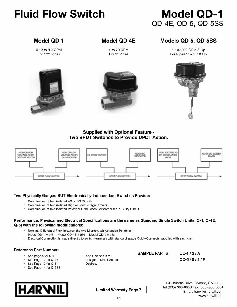
Model QD-1 Model QD-4E Models QD-5, QD-5SS0.12 to 8.0 GPMFor 1/2” Pipes
4 to 70 GPMFor 1” Pipes
5-102,000 GPM & UpFor Pipes 1” - 48” & Up
Two Physically Ganged BUT Electronically Independent Switches Provide:• Combination of two isolated AC or DC Circuits. • Combination of two isolated High or Low Voltage Circuits. • Combination of two isolated Power or Gold Cross Bar computer/PLC Dry Circuit.
Performance, Physical and Electrical Specifications are the same as Standard Single Switch Units (Q-1, Q-4E, Q-5) with the following modifications:
• Nominal Differential Flow between the two Microswitch Actuation Points is - Model QD-1 ≈ 5% Model QD-4E ≈ 5% Model QD-5 ≈ 5%
• Electrical Connection is made directly to switch terminals with standard spade Quick-Connects supplied with each unit.
Reference Part Number:
Fluid Flow Switch Model QD-1QD-4E, QD-5, QD-5SS
Supplied with Optional Feature - Two SPDT Switches to Provide DPDT Action.
541 Kinetic Drive, Oxnard, CA 93030Tel (805) 988-6800 Fax (805) 988-6804
Email. [email protected]
• See page 8 for Q-1• See Page 10 for Q-4E• See Page 12 for Q-5• See Page 14 for Q-5SS
• Add D to part # to designate DPDT Action Desired.
Limited Warranty Page 7
SAMPLE PART #: ! QD-1 / 3 / A! ! ! QD-5 / 5 / 3 / F
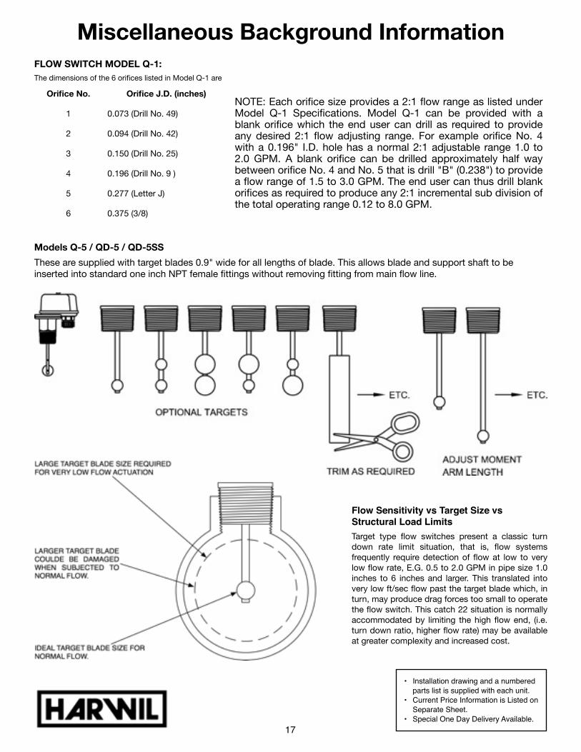
FLOW SWITCH MODEL Q-1:The dimensions of the 6 orifices listed in Model Q-1 are
Orifice No. Orifice J.D. (inches)NOTE: Each orifice size provides a 2:1 flow range as listed under Model Q-1 Specifications. Model Q-1 can be provided with a blank orifice which the end user can drill as required to provide any desired 2:1 flow adjusting range. For example orifice No. 4 with a 0.196" I.D. hole has a normal 2:1 adjustable range 1.0 to 2.0 GPM. A blank orifice can be drilled approximately half way between orifice No. 4 and No. 5 that is drill "B" (0.238") to provide a flow range of 1.5 to 3.0 GPM. The end user can thus drill blank orifices as required to produce any 2:1 incremental sub division of the total operating range 0.12 to 8.0 GPM.
1 0.073 (Drill No. 49)NOTE: Each orifice size provides a 2:1 flow range as listed under Model Q-1 Specifications. Model Q-1 can be provided with a blank orifice which the end user can drill as required to provide any desired 2:1 flow adjusting range. For example orifice No. 4 with a 0.196" I.D. hole has a normal 2:1 adjustable range 1.0 to 2.0 GPM. A blank orifice can be drilled approximately half way between orifice No. 4 and No. 5 that is drill "B" (0.238") to provide a flow range of 1.5 to 3.0 GPM. The end user can thus drill blank orifices as required to produce any 2:1 incremental sub division of the total operating range 0.12 to 8.0 GPM.
2 0.094 (Drill No. 42)
NOTE: Each orifice size provides a 2:1 flow range as listed under Model Q-1 Specifications. Model Q-1 can be provided with a blank orifice which the end user can drill as required to provide any desired 2:1 flow adjusting range. For example orifice No. 4 with a 0.196" I.D. hole has a normal 2:1 adjustable range 1.0 to 2.0 GPM. A blank orifice can be drilled approximately half way between orifice No. 4 and No. 5 that is drill "B" (0.238") to provide a flow range of 1.5 to 3.0 GPM. The end user can thus drill blank orifices as required to produce any 2:1 incremental sub division of the total operating range 0.12 to 8.0 GPM.
3 0.150 (Drill No. 25)
NOTE: Each orifice size provides a 2:1 flow range as listed under Model Q-1 Specifications. Model Q-1 can be provided with a blank orifice which the end user can drill as required to provide any desired 2:1 flow adjusting range. For example orifice No. 4 with a 0.196" I.D. hole has a normal 2:1 adjustable range 1.0 to 2.0 GPM. A blank orifice can be drilled approximately half way between orifice No. 4 and No. 5 that is drill "B" (0.238") to provide a flow range of 1.5 to 3.0 GPM. The end user can thus drill blank orifices as required to produce any 2:1 incremental sub division of the total operating range 0.12 to 8.0 GPM.
4 0.196 (Drill No. 9 )
NOTE: Each orifice size provides a 2:1 flow range as listed under Model Q-1 Specifications. Model Q-1 can be provided with a blank orifice which the end user can drill as required to provide any desired 2:1 flow adjusting range. For example orifice No. 4 with a 0.196" I.D. hole has a normal 2:1 adjustable range 1.0 to 2.0 GPM. A blank orifice can be drilled approximately half way between orifice No. 4 and No. 5 that is drill "B" (0.238") to provide a flow range of 1.5 to 3.0 GPM. The end user can thus drill blank orifices as required to produce any 2:1 incremental sub division of the total operating range 0.12 to 8.0 GPM.
5 0.277 (Letter J)
NOTE: Each orifice size provides a 2:1 flow range as listed under Model Q-1 Specifications. Model Q-1 can be provided with a blank orifice which the end user can drill as required to provide any desired 2:1 flow adjusting range. For example orifice No. 4 with a 0.196" I.D. hole has a normal 2:1 adjustable range 1.0 to 2.0 GPM. A blank orifice can be drilled approximately half way between orifice No. 4 and No. 5 that is drill "B" (0.238") to provide a flow range of 1.5 to 3.0 GPM. The end user can thus drill blank orifices as required to produce any 2:1 incremental sub division of the total operating range 0.12 to 8.0 GPM.
6 0.375 (3/8)
NOTE: Each orifice size provides a 2:1 flow range as listed under Model Q-1 Specifications. Model Q-1 can be provided with a blank orifice which the end user can drill as required to provide any desired 2:1 flow adjusting range. For example orifice No. 4 with a 0.196" I.D. hole has a normal 2:1 adjustable range 1.0 to 2.0 GPM. A blank orifice can be drilled approximately half way between orifice No. 4 and No. 5 that is drill "B" (0.238") to provide a flow range of 1.5 to 3.0 GPM. The end user can thus drill blank orifices as required to produce any 2:1 incremental sub division of the total operating range 0.12 to 8.0 GPM.
Models Q-5 / QD-5 / QD-5SS
These are supplied with target blades 0.9" wide for all lengths of blade. This allows blade and support shaft to be inserted into standard one inch NPT female fittings without removing fitting from main flow line.
Miscellaneous Background Information
• Installation drawing and a numbered parts list is supplied with each unit.
• Current Price Information is Listed on Separate Sheet.
• Special One Day Delivery Available.17
Flow Sensitivity vs Target Size vs Structural Load LimitsTarget type flow switches present a classic turn down rate limit situation, that is, flow systems frequently require detection of flow at low to very low flow rate, E.G. 0.5 to 2.0 GPM in pipe size 1.0 inches to 6 inches and larger. This translated into very low ft/sec flow past the target blade which, in turn, may produce drag forces too small to operate the flow switch. This catch 22 situation is normally accommodated by limiting the high flow end, (i.e. turn down ratio, higher flow rate) may be available at greater complexity and increased cost.

Noryl® Engineering Plastic (PPO) Polyphenylene OxideDuring normal operations flow switches increase efficiency, save time and money by the continuous monitoring of deviations from optimum flow rates. During emergency conditions flow switches signal system malfunctions such as line breakage, pump failure, incorrect valve opening or closing, pipe, valve or filter clogging, etc.
Typical Working Fluids• For use in corrosive liquids such as mild acid and base solutions and related fluids.• Extensive chemical list is available (see page 49).
For use in highly particle-contaminated liquids such as:
Special Features
Fluid Flow Switch Model Q-8N (PPO)8 to 1900 GPM & Up
for pipes 1”- 10” & Up
541 Kinetic Drive, Oxnard, CA 93030Tel (805) 988-6800 Fax (805) 988-6804
Email. [email protected]
• Contaminated Groundwater• Medium Slurries• Rusty Coolant Water
• Sea Water• Sewage• Waste Water
• Particle contamination resistance is provided by a single convolute elastomeric seal which is continually flushed by working fluid flow.
• Wetted surfaces of Noryl®, 316 Stainless Steel, EPDM Elastomeric Standard (Viton® Special Order.)
• Continuous adjustment while operating
• Responds to flow only, independent of line pressure, temperature, environment
• Temperature to 150°F continuous
• Line pressure to 50 psig operating - 100 psig non-operating
• SPDT 15 amp switching capacity model or Dry Computer/PLC Interface model
• Maintenance and checkout is a snap for your present personnel using an uncomplicated standard test meter.
• Maximum flow range flexibility is provided by three adjustment options:• Option 1 - Continuous
adjustment while operating via FORCE/BALANCE spring
• Option 2 - Step incremental adjustment via drag disk size change
• Option 3 - Continuous adjustment via drag disk moment arm change
Available with Optional Filter Boot For Use In Highly Particle Contaminated Liquids
Reliable, Inexpensive
18
Limited Warranty Page 7
MOUNT INANY POSITION
TURBULENT FLOWREDUCTION
COMPONENT RECOGNIZED (E85349)

Model Q-8NFlow Range Water Calibrated @ 70˚FModel Selection Chart
Pipe Size
Flow Limits Between Which Switch Point May Be Set GPM
Model Part Number(Power Cable Interface Option 1 or 2)
18-13 Q-8N /1 /2 /---
118-28 Q-8N /1 /1 /---
1 1/215-30 Q-8N /2 /3 /---
1 1/225-50 Q-8N /2 /1 /---
215-50 Q-8N /2 /3 /---
250-105 Q-8N /2 /1 /---
2 1/240-80 Q-8N /2 /3 /---
2 1/280-155 Q-8N /2 /1 /---
340-90 Q-8N /3 /3 /---
390-180 Q-8N /3 /1 /---
475-155 Q-8N /3 /3 /---
4155-310 Q-8N /3 /1 /---
5120-245 Q-8N /3 /3 /---
5245-480 Q-8N /3 /1 /---
6180-350 Q-8N /3 /3 /---
6350-700 Q-8N /3 /1 /---
8300-600 Q-8N /3 /3 /---
8600-1200 Q-8N /3 /1 /---
10500-950 Q-8N /3 /3 /---
10950-1900 Q-8N /3 /1 /---
LARGE PIPE SIZE INFORMATION AVAILABLE BY REQUEST.LARGE PIPE SIZE INFORMATION AVAILABLE BY REQUEST.LARGE PIPE SIZE INFORMATION AVAILABLE BY REQUEST.
A Four Part Model # Completely Defines Each Unit
Basic Model #
Drag Disk Arm Length (See X)
Drag Disk Size
Input Power Cable Interface Option
Q-8N 1 or 2 or 3 1 or 2 or 3 1 or 2
1=1.15” 1=0.5” dia. SEE BELOW
2=1.85” 2=0.83” dia.
3=3.31” 3=1.0” dia.
Q-8N / / / Q-8N / / / Q-8N / / / Q-8N / / /
Hysteresis (% Flow Change to Activate/Deactivate Switch)• ≈ 10% @ upper end of range• ≈ 30% @ lower end of range
Differential pressure drops across unit(Normal Operating Conditions)
• 1" - 3" pipe - less than 0.5 psi• 4 - 10" pipe - negligible
Working Line Pressure• 50 psig max. @ 180°F Max operating• 100 psig @ 180°F Max non-operating
Wetted Surfaces• Noryl® - (10% glass fibers)• 316 Stainless Steel Standard• EPDM Elastomer (Viton® Special Order)
Electrical Switch Characteristics SPDT UL and CSA listed 15 amp, 1/2 HP @ 125 or 250 VAC 1/2 amp @ 125 VDC (Tungsten lamp load) 10,000,000 operations median
Model Q-8N can also be fitted with a SPDT Gold Cross Bar Switch for computer/PLC interface.Maximum Continuous Temperature: 180°F Optional Filter Boot Available in EPDM, (Viton® Special Order)Weight: 1/2 lb.
19
• Installation drawing and a numbered parts list is supplied with each unit.
• Current Price Information is Listed on Separate Sheet.
• Special One Day Delivery Available.
Input Power Cable Interface Options
Grommet Size
Cable OD
Grommet Size Cable OD
A 0.25” B 0.37”
AA 0.30” C 0.50”
Option No. 1 Sample Part #
Q - 8N / 1 / 1 / B
Basic Model # & Body Material
Grommet Size
Drag Disk Arm Length Drag Disk Size
Option No. 2½” NPT Female
Thread
Q - 8N / 1 / 1 / F
Basic Model # & Body Material
Drag Disk Arm Length Drag Disk Size
Sample Part # Conduit fitting available at additional cost.
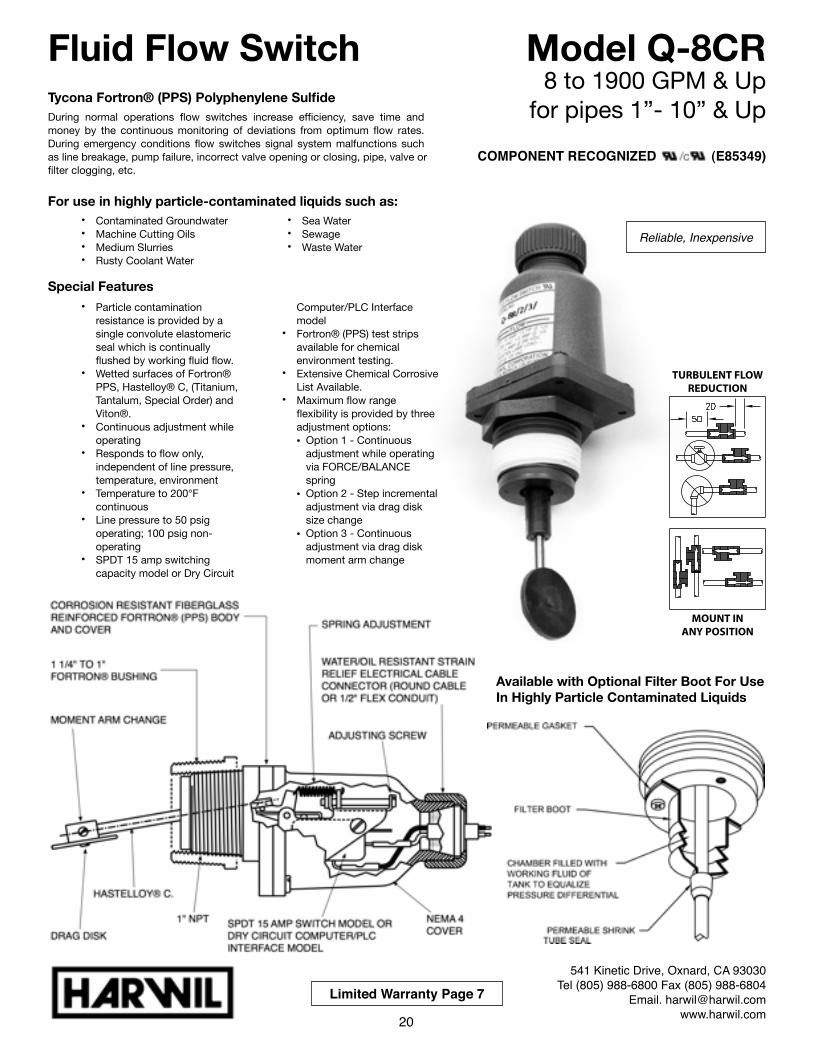
Tycona Fortron® (PPS) Polyphenylene SulfideDuring normal operations flow switches increase efficiency, save time and money by the continuous monitoring of deviations from optimum flow rates. During emergency conditions flow switches signal system malfunctions such as line breakage, pump failure, incorrect valve opening or closing, pipe, valve or filter clogging, etc.
For use in highly particle-contaminated liquids such as:
Special Features
MOUNT INANY POSITION
TURBULENT FLOWREDUCTION
Fluid Flow Switch Model Q-8CR8 to 1900 GPM & Up
for pipes 1”- 10” & Up
541 Kinetic Drive, Oxnard, CA 93030Tel (805) 988-6800 Fax (805) 988-6804
Email. [email protected]
• Contaminated Groundwater• Machine Cutting Oils• Medium Slurries• Rusty Coolant Water
• Sea Water• Sewage• Waste Water
• Particle contamination resistance is provided by a single convolute elastomeric seal which is continually flushed by working fluid flow.
• Wetted surfaces of Fortron® PPS, Hastelloy® C, (Titanium, Tantalum, Special Order) and Viton®.
• Continuous adjustment while operating
• Responds to flow only, independent of line pressure, temperature, environment
• Temperature to 200°F continuous
• Line pressure to 50 psig operating; 100 psig non-operating
• SPDT 15 amp switching capacity model or Dry Circuit
Computer/PLC Interface model
• Fortron® (PPS) test strips available for chemical environment testing.
• Extensive Chemical Corrosive List Available.
• Maximum flow range flexibility is provided by three adjustment options:• Option 1 - Continuous
adjustment while operating via FORCE/BALANCE spring
• Option 2 - Step incremental adjustment via drag disk size change
• Option 3 - Continuous adjustment via drag disk moment arm change
20
Limited Warranty Page 7
Available with Optional Filter Boot For Use In Highly Particle Contaminated Liquids
COMPONENT RECOGNIZED (E85349)
Reliable, Inexpensive
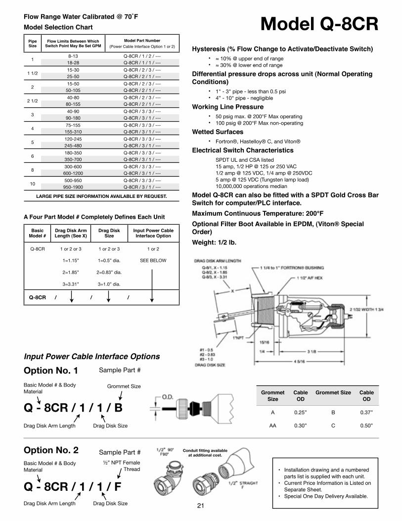
Model Q-8CRFlow Range Water Calibrated @ 70˚FModel Selection Chart
Pipe Size
Flow Limits Between Which Switch Point May Be Set GPM
Model Part Number(Power Cable Interface Option 1 or 2)
18-13 Q-8CR / 1 / 2 / ---
118-28 Q-8CR / 1 / 1 / ---
1 1/215-30 Q-8CR / 2 / 3 / ---
1 1/225-50 Q-8CR / 2 / 1 / ---
215-50 Q-8CR / 2 / 3 / ---
250-105 Q-8CR / 2 / 1 / ---
2 1/240-80 Q-8CR / 2 / 3 / ---
2 1/280-155 Q-8CR / 2 / 1 / ---
340-90 Q-8CR / 3 / 3 / ---
390-180 Q-8CR / 3 / 1 / ---
475-155 Q-8CR / 3 / 3 / ---
4155-310 Q-8CR / 3 / 1 / ---
5120-245 Q-8CR / 3 / 3 / ---
5245-480 Q-8CR / 3 / 1 / ---
6180-350 Q-8CR / 3 / 3 / ---
6350-700 Q-8CR / 3 / 1 / ---
8300-600 Q-8CR / 3 / 3 / ---
8600-1200 Q-8CR / 3 / 1 / ---
10500-950 Q-8CR / 3 / 3 / ---
10950-1900 Q-8CR / 3 / 1 / ---
LARGE PIPE SIZE INFORMATION AVAILABLE BY REQUEST.LARGE PIPE SIZE INFORMATION AVAILABLE BY REQUEST.LARGE PIPE SIZE INFORMATION AVAILABLE BY REQUEST.
A Four Part Model # Completely Defines Each Unit
Basic Model #
Drag Disk Arm Length (See X)
Drag Disk Size
Input Power Cable Interface Option
Q-8CR 1 or 2 or 3 1 or 2 or 3 1 or 2
1=1.15” 1=0.5” dia. SEE BELOW
2=1.85” 2=0.83” dia.
3=3.31” 3=1.0” dia.
Q-8CR / / / Q-8CR / / / Q-8CR / / / Q-8CR / / /
Hysteresis (% Flow Change to Activate/Deactivate Switch)• ≈ 10% @ upper end of range• ≈ 30% @ lower end of range
Differential pressure drops across unit (Normal Operating Conditions)
• 1" - 3" pipe - less than 0.5 psi• 4” - 10" pipe - negligible
Working Line Pressure• 50 psig max. @ 200°F Max operating• 100 psig @ 200°F Max non-operating
Wetted Surfaces• Fortron®, Hastelloy® C, and Viton®
Electrical Switch Characteristics SPDT UL and CSA listed 15 amp, 1/2 HP @ 125 or 250 VAC 1/2 amp @ 125 VDC, 1/4 amp @ 250VDC 5 amp @ 125 VDC (Tungsten lamp load) 10,000,000 operations median
Model Q-8CR can also be fitted with a SPDT Gold Cross Bar Switch for computer/PLC interface.Maximum Continuous Temperature: 200°F Optional Filter Boot Available in EPDM, (Viton® Special Order)Weight: 1/2 lb.
21
• Installation drawing and a numbered parts list is supplied with each unit.
• Current Price Information is Listed on Separate Sheet.
• Special One Day Delivery Available.
Input Power Cable Interface Options
Grommet Size
Cable OD
Grommet Size Cable OD
A 0.25” B 0.37”
AA 0.30” C 0.50”
Option No. 1 Sample Part #
Q - 8CR / 1 / 1 / B
Basic Model # & Body Material
Grommet Size
Drag Disk Arm Length Drag Disk Size
Option No. 2 Sample Part #
Q - 8CR / 1 / 1 / F
Basic Model # & Body Material
Drag Disk Arm Length Drag Disk Size
½” NPT Female Thread
Conduit fitting available at additional cost.
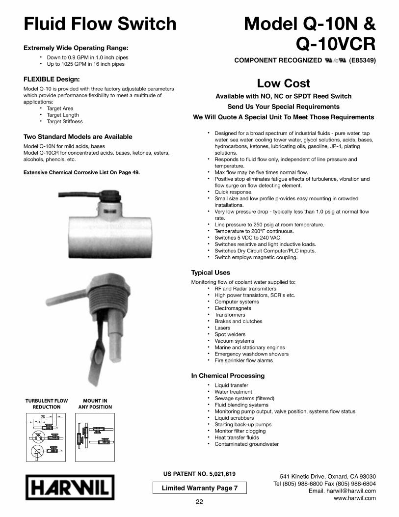
Extremely Wide Operating Range:• Down to 0.9 GPM in 1.0 inch pipes• Up to 1025 GPM in 16 inch pipes
FLEXIBLE Design:Model Q-10 is provided with three factory adjustable parameters which provide performance flexibility to meet a multitude of applications:
• Target Area• Target Length• Target Stiffness
Two Standard Models are AvailableModel Q-10N for mild acids, basesModel Q-10CR for concentrated acids, bases, ketones, esters, alcohols, phenols, etc.
Extensive Chemical Corrosive List On Page 49.
Fluid Flow Switch Model Q-10N & Q-10VCR
541 Kinetic Drive, Oxnard, CA 93030Tel (805) 988-6800 Fax (805) 988-6804
Email. [email protected]
US PATENT NO. 5,021,619
Low CostAvailable with NO, NC or SPDT Reed Switch
Send Us Your Special RequirementsWe Will Quote A Special Unit To Meet Those Requirements
• Designed for a broad spectrum of industrial fluids - pure water, tap water, sea water, cooling tower water, glycol solutions, acids, bases, hydrocarbons, ketones, lubricating oils, gasoline, JP-4, plating solutions.
• Responds to fluid flow only, independent of line pressure and temperature.
• Max flow may be five times normal flow.• Positive stop eliminates fatigue effects of turbulence, vibration and
flow surge on flow detecting element.• Quick response.• Small size and low profile provides easy mounting in crowded
installations.• Very low pressure drop - typically less than 1.0 psig at normal flow
rate.• Line pressure to 250 psig at room temperature.• Temperature to 200°F continuous.• Switches 5 VDC to 240 VAC.• Switches resistive and light inductive loads.• Switches Dry Circuit Computer/PLC inputs.• Switch employs magnetic coupling.
Typical UsesMonitoring flow of coolant water supplied to:
• RF and Radar transmitters• High power transistors, SCR's etc.• Computer systems• Electromagnets• Transformers• Brakes and clutches• Lasers• Spot welders• Vacuum systems • Marine and stationary engines• Emergency washdown showers• Fire sprinkler flow alarms
In Chemical Processing• Liquid transfer • Water treatment• Sewage systems (filtered)• Fluid blending systems• Monitoring pump output, valve position, systems flow status• Liquid scrubbers• Starting back-up pumps• Monitor filter clogging• Heat transfer fluids• Contaminated groundwater
22
Limited Warranty Page 7
MOUNT INANY POSITION
TURBULENT FLOWREDUCTION
COMPONENT RECOGNIZED (E85349)
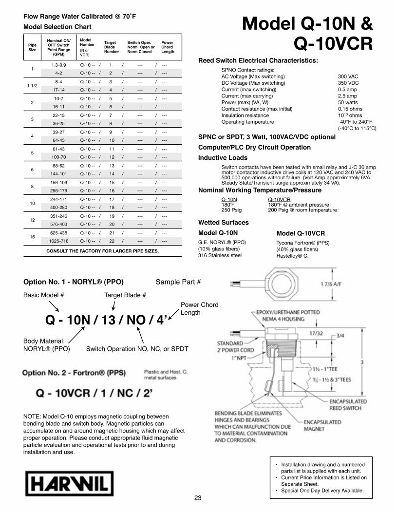
Model Q-10N & Q-10VCR
Flow Range Water Calibrated @ 70˚FModel Selection Chart
Pipe Size
Nominal ON/OFF Switch Point Range
(GPM)
Model Number(N or VCR)
Target Blade Number
Switch Oper. Norm. Open or Norm Closed
Power Chord Length
11.3-0.9 Q-10 -- / 1 / --- / --- Q-10 -- / 1 / --- / --- Q-10 -- / 1 / --- / --- Q-10 -- / 1 / --- / ---
14-2 Q-10 -- / 2 / --- / --- Q-10 -- / 2 / --- / --- Q-10 -- / 2 / --- / --- Q-10 -- / 2 / --- / ---
1 1/28-4 Q-10 -- / 3 / --- / --- Q-10 -- / 3 / --- / --- Q-10 -- / 3 / --- / --- Q-10 -- / 3 / --- / ---
1 1/217-14 Q-10 -- / 4 / --- / --- Q-10 -- / 4 / --- / --- Q-10 -- / 4 / --- / --- Q-10 -- / 4 / --- / ---
210-7 Q-10 -- / 5 / --- / --- Q-10 -- / 5 / --- / --- Q-10 -- / 5 / --- / --- Q-10 -- / 5 / --- / ---
216-11 Q-10 -- / 6 / --- / --- Q-10 -- / 6 / --- / --- Q-10 -- / 6 / --- / --- Q-10 -- / 6 / --- / ---
322-15 Q-10 -- / 7 / --- / --- Q-10 -- / 7 / --- / --- Q-10 -- / 7 / --- / --- Q-10 -- / 7 / --- / ---
336-25 Q-10 -- / 8 / --- / --- Q-10 -- / 8 / --- / --- Q-10 -- / 8 / --- / --- Q-10 -- / 8 / --- / ---
439-27 Q-10 -- / 9 / --- / --- Q-10 -- / 9 / --- / --- Q-10 -- / 9 / --- / --- Q-10 -- / 9 / --- / ---
464-45 Q-10 -- / 10 / --- / --- Q-10 -- / 10 / --- / --- Q-10 -- / 10 / --- / --- Q-10 -- / 10 / --- / ---
561-43 Q-10 -- / 11 / --- / --- Q-10 -- / 11 / --- / --- Q-10 -- / 11 / --- / --- Q-10 -- / 11 / --- / ---
5100-70 Q-10 -- / 12 / --- / --- Q-10 -- / 12 / --- / --- Q-10 -- / 12 / --- / --- Q-10 -- / 12 / --- / ---
688-62 Q-10 -- / 13 / --- / --- Q-10 -- / 13 / --- / --- Q-10 -- / 13 / --- / --- Q-10 -- / 13 / --- / ---
6144-101 Q-10 -- / 14 / --- / --- Q-10 -- / 14 / --- / --- Q-10 -- / 14 / --- / --- Q-10 -- / 14 / --- / ---
8156-109 Q-10 -- / 15 / --- / --- Q-10 -- / 15 / --- / --- Q-10 -- / 15 / --- / --- Q-10 -- / 15 / --- / ---
8256-179 Q-10 -- / 16 / --- / --- Q-10 -- / 16 / --- / --- Q-10 -- / 16 / --- / --- Q-10 -- / 16 / --- / ---
10244-171 Q-10 -- / 17 / --- / --- Q-10 -- / 17 / --- / --- Q-10 -- / 17 / --- / --- Q-10 -- / 17 / --- / ---
10400-280 Q-10 -- / 18 / --- / --- Q-10 -- / 18 / --- / --- Q-10 -- / 18 / --- / --- Q-10 -- / 18 / --- / ---
12351-246 Q-10 -- / 19 / --- / --- Q-10 -- / 19 / --- / --- Q-10 -- / 19 / --- / --- Q-10 -- / 19 / --- / ---
12576-403 Q-10 -- / 20 / --- / --- Q-10 -- / 20 / --- / --- Q-10 -- / 20 / --- / --- Q-10 -- / 20 / --- / ---
16625-438 Q-10 -- / 21 / --- / --- Q-10 -- / 21 / --- / --- Q-10 -- / 21 / --- / --- Q-10 -- / 21 / --- / ---
161025-718 Q-10 -- / 22 / --- / --- Q-10 -- / 22 / --- / --- Q-10 -- / 22 / --- / --- Q-10 -- / 22 / --- / ---
CONSULT THE FACTORY FOR LARGER PIPE SIZES.CONSULT THE FACTORY FOR LARGER PIPE SIZES.CONSULT THE FACTORY FOR LARGER PIPE SIZES.CONSULT THE FACTORY FOR LARGER PIPE SIZES.CONSULT THE FACTORY FOR LARGER PIPE SIZES.CONSULT THE FACTORY FOR LARGER PIPE SIZES.
23
Reed Switch Electrical Characteristics: SPNO Contact ratings: AC Voltage (Max switching) 300 VAC DC Voltage (Max switching) 350 VDC Current (max switching) 0.5 amp Current (max carrying) 2.5 amp Power (max) (VA, W) 50 watts Contact resistance (max initial) 0.15 ohms Insulation resistance 1010 ohms Operating temperature -40°F to 240°F (-40°C to 115°C)
SPNC or SPDT, 3 Watt, 100VAC/VDC optional Computer/PLC Dry Circuit Operation Inductive Loads Switch contacts have been tested with small relay and J-C 30 amp motor contactor inductive drive coils at 120 VAC and 240 VAC to 500,000 operations without failure. (Volt Amp approximately 6VA. Steady State/Transient surge approximately 34 VA).
Nominal Working Temperature/Pressure Q-10N Q-10VCR 180˚F 180°F @ ambient pressure 250 Psig 200 Psig @ room temperature
Wetted SurfacesModel Q-10NG.E. NORYL® (PPO)(10% glass fibers)316 Stainless steel
Model Q-10VCRTycona Fortron® (PPS)(40% glass fibers)Hastelloy® C.
• Installation drawing and a numbered parts list is supplied with each unit.
• Current Price Information is Listed on Separate Sheet.
• Special One Day Delivery Available.
NOTE: Model Q-10 employs magnetic coupling between bending blade and switch body. Magnetic particles can accumulate on and around magnetic housing which may affect proper operation. Please conduct appropriate fluid magnetic particle evaluation and operational tests prior to and during installation and use.
Option No. 1 - NORYL® (PPO) ! Sample Part #
Q - 10N / 13 / NO / 4ʼ
Basic Model # Target Blade #
Body Material: NORYL® (PPO) Switch Operation NO, NC, or SPDT
Power Chord Length

VERY LOW COSTMiniature 1/2" NPT UnitAvailable in SPDT, NO or NC Switch Operation
True Flow Switch Performance Independent of Pressure and Temperature.
Flexible Design• Target area• Target Length• Target stiffness
Which provide performance and flexibility to meet a multitude of pipe sizeand flow rate applications.
Typical Uses
In Chemical Processing
Fluid Flow Switch Model Q-12N & Q-12CR
541 Kinetic Drive, Oxnard, CA 93030Tel (805) 988-6800 Fax (805) 988-6804
Email. [email protected]
US PATENT NO. 5,021,619
24
Limited Warranty Page 7
• Extremely Wide Operating Range:• Down to 0.4 GPM in 3/4 inch pipes• Up to 590 GPM in 8 inch pipes• Many more switch points and pipe sizes
available, consult factory for free analysis.
Send Us Your Special Requirements - We Will Quote A Special Unit To Meet Those Requirements
• Designed for a broad spectrum of industrial fluids - pure water, tap water, sea water, cooling tower water, glycol solutions, acids, bases, hydrocarbons, ketones, lubricating oils, gasoline, JP-4, plating solutions.
• Max flow may be five times normal flow.
• Positive stop essentially eliminates fatigue effects of turbulence, vibration and flow surge on flow detecting element.
• Very low pressure drop - typically less than 1.0 psig at normal flow rate.
• Line pressure to 200 psig.• Temperature to 180°F
continuous.• Switches 5 VDC to 240 VAC.• Power the driving coil of small
ice cube relays as well as some 30 amp power relays.
• Provides dry circuit interface with computer and PLC modules.
• Small size and low profile provides easy mounting in crowded installations.
• Brakes and clutches• Computer systems• Electromagnets• Emergency wash down showers• Fire sprinkler flow alarms• High power transistors, SCR's
etc.• Lasers• Marine and stationary engines
• Monitoring flow and temperature of coolant water supplied to:
- RF and Radar transmitters- Sea water & Fresh water
systems- Spot welders- Transformers- Vacuum systems
• Liquid transfer• Starting back-up pumps• Sewage systems• Fluid blending systems• Monitoring pump output, valve
position, systems flow status
• Liquid scrubbers• Water treatment• Monitor filter clogging• Heat transfer fluidsMOUNT IN
ANY POSITIONTURBULENT FLOW
REDUCTION
NOTE: Model Q-12N employs magnetic coupling between float arm and switch body. Magnetic particles can accumulate on and around magnetic housing which may affect proper operation. Please conduct appropriate fluid magnetic particle evaluation and operational tests prior to and during installation and use.
COMPONENT RECOGNIZED (E85349)
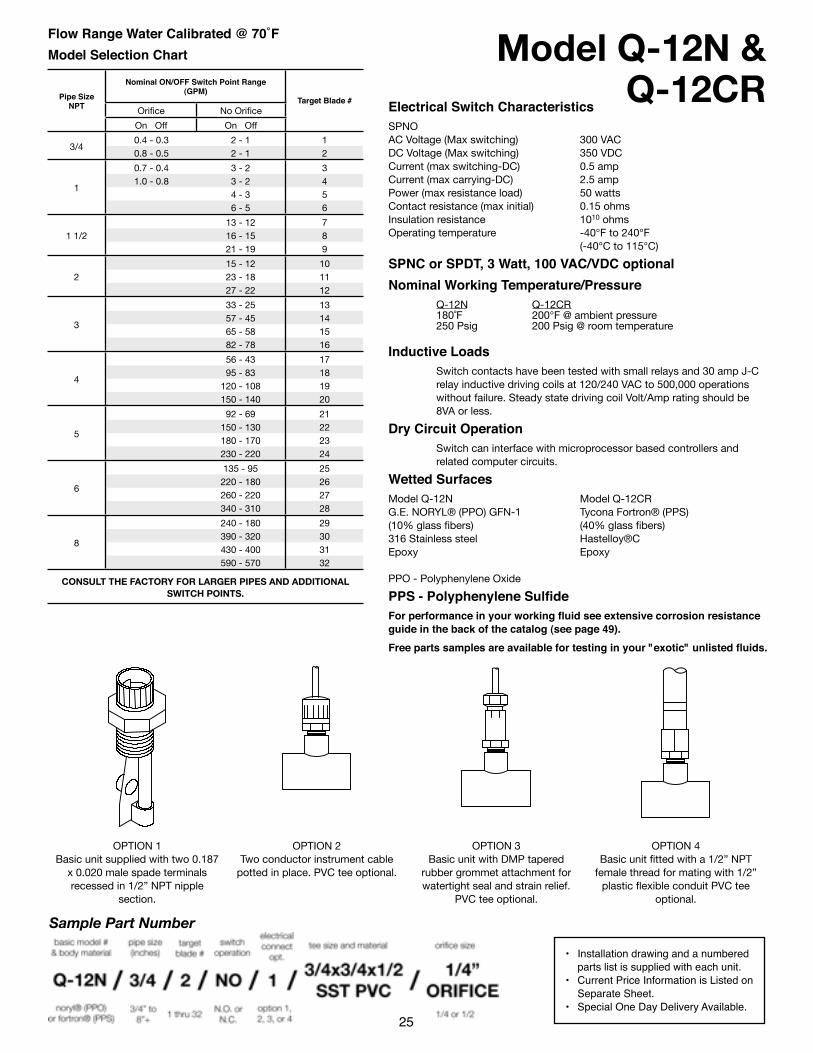
OPTION 1Basic unit supplied with two 0.187
x 0.020 male spade terminals recessed in 1/2” NPT nipple
section.
OPTION 2Two conductor instrument cable
potted in place. PVC tee optional.
OPTION 3Basic unit with DMP tapered
rubber grommet attachment for watertight seal and strain relief.
PVC tee optional.
OPTION 4Basic unit fitted with a 1/2” NPT
female thread for mating with 1/2” plastic flexible conduit PVC tee
optional.
Model Q-12N & Q-12CR
Flow Range Water Calibrated @ 70˚FModel Selection Chart
Pipe Size NPT
Nominal ON/OFF Switch Point Range (GPM)
Nominal ON/OFF Switch Point Range (GPM)
Target Blade #Pipe Size NPT Orifice No Orifice
Target Blade #Pipe Size NPT
On Off On Off
Target Blade #
3/40.4 - 0.3 2 - 1 1
3/40.8 - 0.5 2 - 1 2
1
0.7 - 0.4 3 - 2 3
11.0 - 0.8 3 - 2 4
14 - 3 5
1
6 - 5 6
1 1/213 - 12 7
1 1/2 16 - 15 81 1/221 - 19 9
215 - 12 10
2 23 - 18 11227 - 22 12
3
33 - 25 13
357 - 45 14
365 - 58 15
3
82 - 78 16
4
56 - 43 17
495 - 83 18
4120 - 108 19
4
150 - 140 20
5
92 - 69 21
5150 - 130 22
5180 - 170 23
5
230 - 220 24
6
135 - 95 25
6220 - 180 26
6260 - 220 27
6
340 - 310 28
8
240 - 180 29
8390 - 320 30
8430 - 400 31
8
590 - 570 32
CONSULT THE FACTORY FOR LARGER PIPES AND ADDITIONALSWITCH POINTS.
CONSULT THE FACTORY FOR LARGER PIPES AND ADDITIONALSWITCH POINTS.
CONSULT THE FACTORY FOR LARGER PIPES AND ADDITIONALSWITCH POINTS.
CONSULT THE FACTORY FOR LARGER PIPES AND ADDITIONALSWITCH POINTS.
Electrical Switch CharacteristicsSPNOAC Voltage (Max switching) 300 VACDC Voltage (Max switching) 350 VDCCurrent (max switching-DC) 0.5 ampCurrent (max carrying-DC) 2.5 ampPower (max resistance load) 50 wattsContact resistance (max initial) 0.15 ohmsInsulation resistance 1010 ohmsOperating temperature -40°F to 240°F (-40°C to 115°C)
SPNC or SPDT, 3 Watt, 100 VAC/VDC optionalNominal Working Temperature/Pressure Q-12N Q-12CR 180˚F 200°F @ ambient pressure 250 Psig 200 Psig @ room temperature
Inductive Loads Switch contacts have been tested with small relays and 30 amp J-C relay inductive driving coils at 120/240 VAC to 500,000 operations without failure. Steady state driving coil Volt/Amp rating should be 8VA or less.
Dry Circuit Operation Switch can interface with microprocessor based controllers and related computer circuits.
Wetted SurfacesModel Q-12N Model Q-12CRG.E. NORYL® (PPO) GFN-1 Tycona Fortron® (PPS)(10% glass fibers) (40% glass fibers)316 Stainless steel Hastelloy®CEpoxy Epoxy
PPO - Polyphenylene Oxide
PPS - Polyphenylene SulfideFor performance in your working fluid see extensive corrosion resistance guide in the back of the catalog (see page 49).Free parts samples are available for testing in your "exotic" unlisted fluids.
• Installation drawing and a numbered parts list is supplied with each unit.
• Current Price Information is Listed on Separate Sheet.
• Special One Day Delivery Available.25
Sample Part Number