fluid flow effects in ald for semiconductor...
TRANSCRIPT

Fluid Flow Effects in ALD for
Semiconductor Manufacturing
Juan Pablo Trelles1 and Sandy Liao2
1 Design and Technology Solutions, Intel Corporation, Hillsboro, OR 97124, U. S. A.;
[email protected] Portland Technology Development, Intel Corporation, Hillsboro, OR 97124, U. S. A.;
11th International Conference on Atomic Layer Deposition (ALD 2011)
Cambridge, MA - June 28, 2011
1

ALD @ Intel
2
• Moore’s Law and the Semiconductor Research Roadmap
1. M. Bohr, Silicon Technology for 32 nm and Beyond System-on-Chip Products, IDF 2009
2. Intel Technology Journal, ISSN 1535-864X DOI 10.1535/itj.1202.01
• Since High-k Metal Gate ALD technology enabler
• ALD for High-Volume Manufacturing (HVM)o cost (precursors, equipment, throughput),
o control, reliability, yield, …
2
1st gen high-k metal gate
2nd gen high-k metal gate
1
3-D tri-gate transistors (22 nm)

)()()()()(
)()()( )()(
2
1
bAgCsBsAgB
bBgCsAsBgA
k
k
precursors surface termination bi-products film
ALD Chemistry
3
inject A insert B
inject B insert A
time
B(b) in A(b) inbi-prod out
bulk
AB film
bi-prod out
+ D(g), dilutant always present
• “Complementary Self-Limiting Surface Reactions”
• “Canonical” ideal ALD of A-B film
(g): gas, (s): surface, (b): bulk
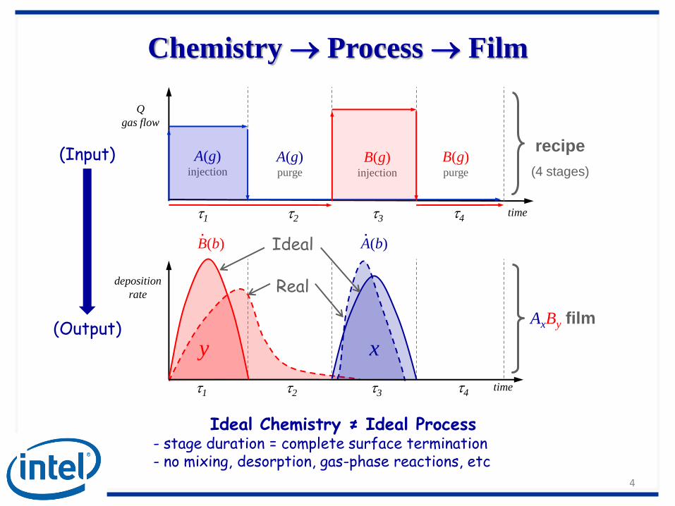
Chemistry Process Film
4
(Input)
(Output)
Ideal Chemistry ≠ Ideal Process- stage duration = complete surface termination- no mixing, desorption, gas-phase reactions, etc
A(g)injection
B(g)injection
A(g)purge
B(g)purge
time
Q
gas flow
t1 t2 t3 t4
recipe
(4 stages)
Real
AxBy film
t1 t2 t3 t4time
deposition
rate
Ideal
y x
B(b).
A(b).

exhaust
Qin
wafer stack
Qout
ALD Reactor for HVM
• Multi-substrate batch reactor: 1 inlet (injector), 1 outlet (exhaust), 4 wafers
5
injector
Qin
Flow effects limit ideal ALD
dissimilar flow
resistance
non-uniform injection
recirculation
stagnation

Patterned Surfaces & ALD Chemistry
• ALD in semiconductor technology: (geometric) Multi-Scale
6
• Patterned topography increases substrate areao Process from “diffusion limited” to “reaction limited”
• Need to model effect of patterns in ALD process, e.g. Site Density ()
1. Intel Press Release, Intel First to Demonstrate Working 45nm Chips, 2006
blank
blank
pattern
patternblankpatternA
Af )(
ratio area
1
~ 10 cm
~ 1 cm ~ 1 um
wafer 1die pattern feature
~ 10 nm

Deposition ProcessConditions:
• Ideal A-B chemistry
• k1 = k2
• rB = 1.2 rA
• pattern = 5blank
• rQin const.
• 100% B(s) initial surf. term.
• D(g) pressure loading
• P ~ Torr (Kn << 1)
7
B(b) depositionB(s) consumptionA(g) transport +
A(g)
Qin

A(g) 1
2
3
4
5
6
7
Precursor Transport
8
A(g)
2 73 5 64
stagnant precursor residual deposition
non-uniform injection different deposition

Stagnation & Recirculation
9
Fluid Flow effects limit applicability of “estimates” in recipe formulation
1 2
recirculation inside injector:non-uniform injection, mixing
1A(g)
stagnant bi-products:reduce available Pv
1
2
C(g)
C(g)
dragging of stagnant gas: mixing, non-ALD growth
2B(g)
A(g)

Reactor Filling
10
reactor
inj. tube
• delay Pmax inj. line – reactor
• Pmin line Pmax reactor
Helmholtz resonator
delay• Pressure: line vs. reactor
• loading > 1 cycle
• by-product limits deposition
ideal = no bi-products
• Gas mass fraction:
loading bi-product

ALD Recipe
11
CaseTime
Total Cycle
Time
Purge/Total
Growth
rate
Max
A(s)
I 50% T 1/2 59% 65%
II 50% T 2/3 63% 67%
III 75% T 2/3 93% 99%
IV 100% T 2/3 100% 100% complete
~ optimal
non-ALD
non-ALD
ALD
non-ALD
A(s) fractional coverage • inj. time growth rate• purge time ALD• purge time > 2/3 cycle• “optimal” recipe limited by flow effects
• optimal:+25% shorter cycle-7% growth rate

Summary
• ALD for HVM challenges: Fluid Flow Effects– Recirculation, Stagnation, Dissimilar Transport, etc.
– Increasing process throughput limits “ideal ALD”
• Patterned substrates affect process performance
– Increases effective area
• Bi-products detrimental
– Bi-product pressure <> precursor vapor pressure
• Steady-State driven by pressure oscillations (i.e., Helmholtz resonator)
• Most time spent in purges (i.e., no deposition, termination)
– 2/3 cycle time typical
– room for improvement? … <1/2 cycle possible?
12
Thank You