fluence z.e. driver’s handbook - renaultie.e-guide.renault.com/.../fluence_ze_-_914-4_eng.pdf ·...
TRANSCRIPT

FLUENCEFLUENCE Z.E.Z.E.
DRIVER’S HANDBOOKDRIVER’S HANDBOOK

0.1
Translated from French. Copying or translation, in part or in full, is forbidden unless prior written permission has been obtained from the vehicle manu-facturer.
This driver’s handbook contains the information necessary:– for you to familiarise yourself with your vehicle, to use it to its best advantage and to benefit fully from the all the functions and
the technical developments it incorporates.– to ensure that it always gives the best performance by following the simple, but comprehensive advice concerning regular main-
tenance.– to enable you to deal quickly with minor faults not requiring specialist attention.It is well worth taking a few minutes to read this handbook to familiarise yourself with the information and guidelines it contains about the vehicle and its functions and new features. If certain points are still unclear, our Network technicians will be only too pleased to provide you with any additional information.The following symbol will help you when reading this handbook:
Welcome to your new electric vehicle
The descriptions of the models given in this handbook are based on the technical specifications at the time of writing. This hand-book covers all items of equipment (both standard and optional) available for these models but whether or not these are fitted to the vehicle depends on the version, options selected and the country where the vehicle is sold.This handbook may also contain information about items of equipment to be introduced later in the model year.Throughout the manual, the “approved Dealer” is your RENAULT Dealer.
To indicate a hazard, danger or safety recommendation.
Enjoy driving your new vehicle.

0.2

0.3
Getting to know your vehicle ...............................
Driving ...................................................................
Your comfort .........................................................
Maintenance .........................................................
Practical advice ....................................................
Technical specifications ......................................
Alphabetical index ...............................................
Sections
1
C O N T E N T S
2
3
4
5
6
7

0.4

1.1
Section 1: Getting to know your vehicle
Electric vehicle: introduction . . . . . . . . . . . . . . . . . . . . . . . . . . . . . . . . . . . . . . . . . . . . . . . . . . . . . . . 1.2Important recommendations . . . . . . . . . . . . . . . . . . . . . . . . . . . . . . . . . . . . . . . . . . . . . . . . . . . . . . . 1.7Electric vehicle: charging . . . . . . . . . . . . . . . . . . . . . . . . . . . . . . . . . . . . . . . . . . . . . . . . . . . . . . . . . . 1.8Traction battery quick change system . . . . . . . . . . . . . . . . . . . . . . . . . . . . . . . . . . . . . . . . . . . . . . . . 1.14Key, radio frequency remote control: general information, use, deadlocking . . . . . . . . . . . . . . . . . . 1.15Doors . . . . . . . . . . . . . . . . . . . . . . . . . . . . . . . . . . . . . . . . . . . . . . . . . . . . . . . . . . . . . . . . . . . . . . . . . 1.17Automatic locking when driving . . . . . . . . . . . . . . . . . . . . . . . . . . . . . . . . . . . . . . . . . . . . . . . . . . . . . 1.21Headrests - Seats . . . . . . . . . . . . . . . . . . . . . . . . . . . . . . . . . . . . . . . . . . . . . . . . . . . . . . . . . . . . . . . 1.22Seat belts. . . . . . . . . . . . . . . . . . . . . . . . . . . . . . . . . . . . . . . . . . . . . . . . . . . . . . . . . . . . . . . . . . . . . . 1.26Methods of restraint in addition to the child seat belts. . . . . . . . . . . . . . . . . . . . . . . . . . . . . . . . . . . . 1.29
in addition to the rear seat belts . . . . . . . . . . . . . . . . . . . . . . . . . . . . . . . . . . . . . . . . . . . . . . . 1.33side protection . . . . . . . . . . . . . . . . . . . . . . . . . . . . . . . . . . . . . . . . . . . . . . . . . . . . . . . . . . . . 1.34
Steering wheel/Power-assisted steering . . . . . . . . . . . . . . . . . . . . . . . . . . . . . . . . . . . . . . . . . . . . . . 1.36Child safety: general information . . . . . . . . . . . . . . . . . . . . . . . . . . . . . . . . . . . . . . . . . . . . . . . . . . . . 1.37
Choosing a child seat mounting . . . . . . . . . . . . . . . . . . . . . . . . . . . . . . . . . . . . . . . . . . . . . . . 1.40fitting a child seat . . . . . . . . . . . . . . . . . . . . . . . . . . . . . . . . . . . . . . . . . . . . . . . . . . . . . . . . . . 1.42deactivating, activating the front passenger airbag . . . . . . . . . . . . . . . . . . . . . . . . . . . . . . . . 1.46
Clock and exterior temperature . . . . . . . . . . . . . . . . . . . . . . . . . . . . . . . . . . . . . . . . . . . . . . . . . . . . . 1.49Driving position . . . . . . . . . . . . . . . . . . . . . . . . . . . . . . . . . . . . . . . . . . . . . . . . . . . . . . . . . . . . . . . . . 1.50Warning lights . . . . . . . . . . . . . . . . . . . . . . . . . . . . . . . . . . . . . . . . . . . . . . . . . . . . . . . . . . . . . . . . . . 1.54Displays and indicators . . . . . . . . . . . . . . . . . . . . . . . . . . . . . . . . . . . . . . . . . . . . . . . . . . . . . . . . . . . 1.57On-board computer . . . . . . . . . . . . . . . . . . . . . . . . . . . . . . . . . . . . . . . . . . . . . . . . . . . . . . . . . . . . . . 1.59Vehicle settings personalisation menu . . . . . . . . . . . . . . . . . . . . . . . . . . . . . . . . . . . . . . . . . . . . . . . 1.68Door mirrors . . . . . . . . . . . . . . . . . . . . . . . . . . . . . . . . . . . . . . . . . . . . . . . . . . . . . . . . . . . . . . . . . . . . 1.69Audible and visual signals . . . . . . . . . . . . . . . . . . . . . . . . . . . . . . . . . . . . . . . . . . . . . . . . . . . . . . . . . 1.70Exterior lighting and signals. . . . . . . . . . . . . . . . . . . . . . . . . . . . . . . . . . . . . . . . . . . . . . . . . . . . . . . . 1.71Adjusting the headlight beam height . . . . . . . . . . . . . . . . . . . . . . . . . . . . . . . . . . . . . . . . . . . . . . . . . 1.74Windscreen washers and wipers . . . . . . . . . . . . . . . . . . . . . . . . . . . . . . . . . . . . . . . . . . . . . . . . . . . . 1.75

1.2
1 Electric motor2 Electric charging connections3 Traction battery4 Orange electrical power cables5 12 volt battery
3
4
5
1 2
2
ELECTRIC VEHICLE: introduction (1/5)

1.3
ELECTRIC VEHICLE: introduction (2/5)Electric vehicles have special features, but operate in a similar manner to con-ventional vehicles.The main difference in electric vehicles is the exclusive use of electric energy instead of fuel, as used in convention vehicles.We therefore recommend that you read these instructions describing your elec-tric vehicle carefully.
Connected services(depending on vehicle)Your electric vehicle has connected services which enable it to determine the charge status, among other things, using mobile phones 7 or your compu-ter 8. This information is also available directly on the instrument panel 6 of your vehicle.For further information, please contact an authorised dealer.
You can subscribe to a connected service or extend it at any time by consulting an authorised dealer.
6 7
8
1.4
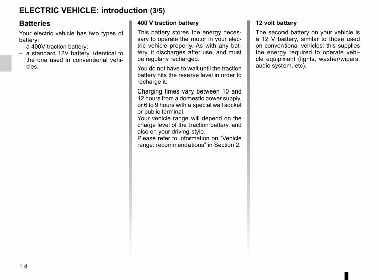
BatteriesYour electric vehicle has two types of battery:– a 400V traction battery;– a standard 12V battery, identical to
the one used in conventional vehi-cles.
400 V traction batteryThis battery stores the energy neces-sary to operate the motor in your elec-tric vehicle properly. As with any bat-tery, it discharges after use, and must be regularly recharged.You do not have to wait until the traction battery hits the reserve level in order to recharge it.Charging times vary between 10 and 12 hours from a domestic power supply, or 6 to 9 hours with a special wall socket or public terminal.Your vehicle range will depend on the charge level of the traction battery, and also on your driving style.Please refer to information on “Vehicle range: recommendations” in Section 2.
12 volt batteryThe second battery on your vehicle is a 12 V battery, similar to those used on conventional vehicles: this supplies the energy required to operate vehi-cle equipment (lights, washer/wipers, audio system, etc).
ELECTRIC VEHICLE: introduction (3/5)

1.5
The vehicle drive system in an electric vehicle uses an alternating voltage of ap-proximately 400 volts. This
system can get hot during and after switching off the ignition. Respect warning messages given on the labels in the vehicle.All interventions or modifications to the 400V electrical system (com-ponents, cables, connectors, trac-tion battery) are strictly prohibited due to the risks they present to your safety. Please contact an authorised dealer.The risk of serious burns or elec-tric shocks can lead to death.
A
ELECTRIC VEHICLE: introduction (4/5)
The A symbol denotes the electrical elements of your vehicle which may present health risks.
4
400 volt electrical circuitThe 400V electrical circuit is denoted by orange cables 4 and parts bearing the � symbol.

1.6
ELECTRIC VEHICLE: introduction (5/5)
NoiseElectric vehicles are particularly quiet. You will not yet necessarily be used to it, and neither will other road users. It is difficult for them to hear the vehicle when it is moving. We recommend that you take this into account, especially when driving in urban environments and when performing manoeuvres.As the motor is silent, you will hear noises that you are not used to hearing (aerodynamic noises, tyre noise, etc.)When charging, the vehicle may emit noises (fan, relays, etc).
Your electric vehicle is very quiet. When getting out of the vehicle, always check that the gear selector is
at P, engage the handbrake and switch off the ignition.RISK OF SERIOUS INJURY
The engine brake should under no circumstances be used as a substitute for the brake pedal.
DrivingAs with a car with an automatic gear-box, you will have to get used to not using your left foot, and not using this foot to brake.When driving, if you lift your foot off the accelerator pedal or depress the brake pedal, the motor generates electrical current during deceleration, and this energy is used to brake the vehicle and recharge the traction battery. Please refer to the information on the “Charge meter” in Section 2.An electric motor generates a greater engine brake than in a petrol or diesel engine vehicle.
Special conditionsAfter a maximum charge of the battery and during the first few miles of using the vehicle, the engine brake will be temporarily reduced. Please adapt your driving style appropriately.
Bad weather, flooded roads:
Do not drive through floods if the depth of water is above the lower edge of the wheel rims.
Obstructions to the driverOn the driver’s side, only use mats suitable for the vehicle, attached with the
pre-fitted components, and check the fitting regularly. Do not lay one mat on top of another.There is a risk of wedging the pedals

1.7
IMPORTANT RECOMMENDATIONS
Please read these instructions carefully. Failure to follow these instructions may lead to a risk of fire, serious injury or electric shock which may present a risk to life.
In the event of an accident or impactIn the event of an accident or an impact to the underside of the vehicle (e.g.: striking a post, raised kerb or other street furni-ture), this may damage the electric circuit or the traction battery.Have the vehicle checked by an authorised dealer.Never touch the “400 volt” components or orange cables which are exposed and visible inside or outside the vehicle.In the event of serious damage to the traction battery, leaks may occur:– never touch the liquids (fluids, etc.) coming from the traction battery;– in the event of contact with the body, wash the affected area with plenty of water and consult a doctor as soon as possible.In the event of an impact, even slight, against the charging flap and/or valve, have them checked by an authorised dealer as soon as possible.
In the event of fireIn the event of fire, make everyone evacuate the vehicle immediately and contact the emergency services, informing them that this is an electric vehicle.Only use extinguishing agents ABC or BC that are permitted for use with electrical fires. Do not use water or other extinguish-ing agents.In the event of damage to the electrical circuit, please call an authorised dealer.
All towing operationsPlease refer to the information on “Towing, breakdowns” in Section 5.
Washing the vehicleNever wash the engine compartment, the charging connection or the traction battery with a high-pressure jet.This risks damaging the electric circuit.Never wash the vehicle while it is charging. Risk of electric shock and a risk to life.

1.8
ELECTRIC VEHICLE: charging (1/6)
Charging schematic diagram1 Electric charging connections2 Specific wall socket or recharging ter-
minal3 Charging cord
1
If you have any questions regarding the equipment needed for charging, please ask an authorised dealer.
2
31

1.9
ELECTRIC VEHICLE: charging (2/6)
Important recommendations for charging your vehiclePlease read these instructions carefully. Failure to follow these instructions may lead to a risk of fire, serious injury or electric shocks which could result in death.Installation for using a standard charging cord
Have a special wall socket installed by a qualified professional.Installation for using an occasional charging cordHave a qualified professional check that each socket you intend to use with the occasional charging cord complies with the standards and regulations in force in your country, especially that they have:– a Type A residual differential current of 30 mA;– a device to protect against overvoltage (16A fuse or circuit breaker for the socket used);– protection against overvoltage relating to lightning in exposed areas.You are recommended to test the residual differential current device every month.You are recommended to check regularly the domestic power supply as well as the special wall socket. In the event of dete-rioration (corrosion, browning, etc.), do not use it.Please read the instructions that come with the occasional charging cord carefully to learn about usage precautions and how to use the cord.
ChargingDo not do anything to the vehicle during charging (washing, working in the engine compartment, etc.).In the event of the presence of water, signs of corrosion or foreign bodies in the charging cord connector or in the vehicle charg-ing socket, do not charge the vehicle. Fire hazard.Do not attempt to touch the cord contacts, the domestic socket or the vehicle charging socket, or introduce objects into them.Never plug the charging cord into a multiple socket or an extension lead.Do not remove or change the vehicle charging socket or the charging cord. Fire hazard.Do not modify the installation during charging.In the event of an impact, even slight, against the charging socket or valve, have them checked by an authorised dealer as soon as possible.Take care of the cord: do not tread on it, immerse it in water or pull on it or let anything knock against it. Check regularly that the charging cord is in good condition. In the event of deterioration (corrosion, browning, cuts, etc.), do not use it.

1.10
Never leave the socket hanging by the cord. Use points 5 to hold it.
ELECTRIC VEHICLE: charging (3/6)
Charging cord for standard
charging 3This cord, designed specifically for wall sockets or public terminals, enables a full recharge of the traction battery in around 6 to 9 hours.
Occasional usage charging cord 4(depending on vehicle)This occasional charging cord 4, for do-mestic sockets, enables a full recharge of the traction battery in around 10 to 12 hours.This cord 4 should only be used for oc-casional charges in accordance with the installation conditions set out above.
In the event of a problem, we rec-ommend that you replace it with an identical cord. Please see an au-thorised dealer.
5
5
4
Do not use an extension lead, multiple socket or adapter.Fire hazard.
You are recommended to use cord 3 as a priority for charging the traction battery.
3
4
Charging cords 3 and 4 are stored in a bag in the boot of the vehicle.

1.11
ELECTRIC VEHICLE: charging (4/6)
Charging sockets 1The vehicle has a charging socket on each side of the vehicle.
Do not connect a cord at both ve-hicle charging sockets at the same time.
1
Avoid charging and parking your ve-hicle in extreme temperatures (hot or cold).When the vehicle is parked in tempera-tures lower than around -25°C, the bat-tery cannot be charged.Favour charging the traction battery after driving and/or in mild tempera-tures. Otherwise, charging may take a longer period of time or even become impossible.
In the absence of any protection against overvoltage, you are recom-mended not to charge the vehicle in stormy weather (lightning, etc).
Recommendations– In high temperatures, try to park and
recharge the vehicle in a shaded/covered location.
– Charging can be performed in the rain or snow.
Note:If in a snowy environment, remove snow from the vehicle charging area before plugging in or disconnecting. Snow in the socket may block the in-sertion of the charging cord plug.

1.12
ELECTRIC VEHICLE: charging (5/6)
86
7
9
– open charging flap 6;– open valve 7;– grab handle 9;– plug in the vehicle cord;– make sure you have clicked the
charging cord in properly. To check the locks, pull on the handle with moderate force 9 without pressing button 8.
Warning light � comes on the instru-ment panel.If you wish, you can then lock your ve-hicle. This will make it impossible to unplug the cord from your vehicle.
Recharging the traction batterySwitch the ignition off and unlock the opening elements:– take the charging cord located in the
boot of your vehicle;– remove it from its storage bag;– plug in the end of the cord to the
power supply (terminal, domestic plug socket, etc);
When charging commences, the hazard warning lights will flash five times. A message on the instrument panel will tell you the remaining charging time.You do not need to wait until the charge is at reserve levels to recharge your ve-hicle.
Precautions to take when removing from the socket– Check that the opening elements are
unlocked;– grab handle 9 and press button 8;– unplug the charging cord from the
vehicle while holding down button 8. Warning light � goes out on the instrument panel;
– close valve 7 then flap 6;– unplug the cord from the power
supply;– store the cord in its storage bag and
put away in the boot.
The charging cord cannot be plugged in or removed while the opening elements are locked.
NB: It does not matter about the order of plugging in/unplugging of the charging cord between the vehi-cle and the power supply.

1.13
ELECTRIC VEHICLE: charging (6/6)
Operation notice regarding the occasional charging cord socket 4
4
10
11
12
Warning lights
ReadingREADY 10Green
CHARGE 11Orange
FAULT 12Red
Switched on 0.5 seconds
Switched on0.5 seconds
Switched on0.5 seconds
When switching on, the warning lights go on for half a second to check that they are operating cor-rectly.
Switched on Switched off Switched off The charging cord is plugged in to the domestic plug socket and the traction battery has finished charg-ing.
Switched on Switched on Switched off The traction battery is charging.
Switched on Switched off Switched on or flashing
Operating fault. Unplug the cord and contact an authorised dealer.
Switched off Switched off Switched off No electrical power has been de-tected at the domestic power socket. Check your electrical installation (circuit breaker, etc.) and start again.If the problem persists, unplug the cord and contact an authorised dealer.

1.14
TRACTION BATTERY QUICK CHANGE SYSTEM
At an exchange point, it is possible to change the traction battery of the vehi-cle with a charged battery, as shown in the schematic diagram above.Do not forget to switch off the ignition when replacing the traction battery.
Follow the instructions given at the exchange point. Messages will be displayed on the instrument panel if these instructions are not followed.Risk of damage to the vehicle.

1.15
KEY/RADIO FREQUENCY REMOTE CONTROL: general information
41
2
3
5
Radio frequency remote control operating rangeThis varies according to the surround-ings: please take care not to lock or unlock the doors by inadvertently press-ing the buttons on the remote control.InterferenceThe presence of certain objects (metal objects, mobile telephones, or an area with strong electromagnetic radiation, etc.) close to the key may create inter-ference and affect the operation of the system.
Radio frequency remote control 1 Locking the doors and tailgate. 2 Unlocking the doors and tailgate. 3 Driver’s door and ignition key. 4 To release the key from its hous-
ing, press button 4. It will be re-leased automatically.
To reinsert it in its housing, press button 4 and guide the key into the storage position.
5 Unlocking/Locking the boot only.
The key must not be used for any function other than those described in the handbook (removing the cap from a bottle, etc.).
For replacement, or if you require an additional remote controlIf you lose your remote control or require another, you can obtain one from an approved Dealer.If a remote control is replaced, it will be necessary to take the vehi-cle and all of its remote controls to an approved Dealer to initialise the system.You may use up to four remote con-trol units per vehicle.
Remote control unit failureMake sure that the correct battery type is being used, and that the battery is in good condition and in-serted correctly. These batteries have a service life of approximately two years.Refer to the information on “Radio frequency remote control: Batteries” in Section 5.
AdviceAvoid leaving the remote control in hot, cold or humid areas.

1.16
Unlocking the doorsPress button 2 to unlock.The hazard warning lights and indica-tor lights flash once to indicate that the doors have unlocked.NB: unlocking the doors will unlock the vehicle charging cord.
KEY/RADIO FREQUENCY REMOTE CONTROL: use
Locking the doorsPress locking button 1.The indicator lights and hazard warning lights flash twice to indicate that the doors have locked:If an opening element (door or boot) is open or not properly closed, the open-ing elements quickly lock then unlock and the hazard warning lights and indi-cator lights do not flash.NB: while charging the traction battery, locking the opening elements will lock the vehicle charging cord.
3
1
2
Unlocking/locking the boot only(for some countries)Press button 3 to unlock or lock the boot.The hazard warning lights and indica-tor lights flash once to indicate that the tailgate is unlocked if the vehicle doors are locked.The hazard warning lights and indica-tor lights flash twice to indicate that the luggage compartment lid is locked if the vehicle doors are locked.
Driver’s responsibilityNever leave your vehi-cle with the key inside and never leave a child (or a
pet) unsupervised, even for a short while.They may pose a risk to themselves or to others by starting the engine, activating equipment such as the electric windows or by locking the doors.Risk of serious injury.
The card buttons are deactivated when the engine is running.The flashing status of the hazard warning lights informs you of the ve-hicle status:– one flash indicates that the vehi-
cle is completely unlocked;– two flashes indicate that the ve-
hicle is completely locked.
1.17
OPENING AND CLOSING THE DOORS (1/2)
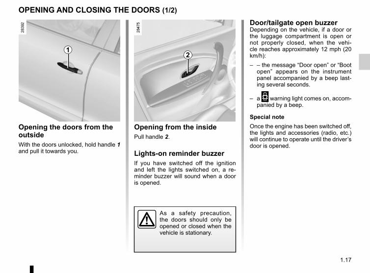
Opening the doors from the outsideWith the doors unlocked, hold handle 1 and pull it towards you.
Opening from the insidePull handle 2.
Lights-on reminder buzzerIf you have switched off the ignition and left the lights switched on, a re-minder buzzer will sound when a door is opened.
Door/tailgate open buzzerDepending on the vehicle, if a door or the luggage compartment is open or not properly closed, when the vehi-cle reaches approximately 12 mph (20 km/h):– – the message “Door open” or “Boot
open” appears on the instrument panel accompanied by a beep last-ing several seconds.
– a 2 warning light comes on, accom-panied by a beep.
Special noteOnce the engine has been switched off, the lights and accessories (radio, etc.) will continue to operate until the driver’s door is opened.
12
As a safety precaution, the doors should only be opened or closed when the vehicle is stationary.

1.18
OPENING AND CLOSING THE DOORS (2/2)
Driver’s responsibility when parking or stopping the vehicleNever leave an animal,
child or adult who is not self-suffi-cient alone on your vehicle, even for a short time.They may pose a risk to themselves or to others by starting the engine, activating equipment such as the electric windows or by locking the doors.Also, in hot and/or sunny weather, please remember that the tempera-ture inside the passenger compart-ment increases very quickly.RISK OF DEATH OR SERIOUS INJURY.
Child safety
Ç Vehicle with switch 3Press switch 3 to enable the
rear doors to be opened. If the vehicle is equipped with electric rear windows, this action will also enable their use.The indicator light in the switch lights up to confirm that the locks have been ac-tivated.
Safety of rear occupantsThe driver can enable op-eration of the rear doors and, depending on the ve-
hicle, the electric windows by press-ing switch 3 on the side with the il-lustration.Depending on the vehicle, in the event of a fault:– a beep sounds;– a message is displayed on the in-
strument panel;– the integrated indicator does not
light up.If the battery has been discon-nected, press switch 3 on the side with the symbol to lock the rear doors.
3

1.19
LOCKING/UNLOCKING THE DOORS (1/2)
Locking/Unlocking the doors from the outsidePlease refer to the information on the “Key/Radio frequency remote control” in Section 1.In some cases, the radio frequency remote control will not operate, or its access area will be modified:– the remote control battery is old
or the vehicle 12 V battery is dis-charged.
– the vehicle is located in a high elec-tromagnetic radiation zone.
It is then possible:– to use the key integrated in the radio
frequency remote control to unlock the front left-hand door;
– to lock each of the doors manually;– to use the interior door locking/un-
locking control (refer to the following pages).
Using the keyInsert key 1 into the lock A of the driv-er’s door to lock or unlock the door.
Locking the doors manuallyTurn screw 2 with the door open (using the end of the key) and close the door.This means that the doors are then locked from the outside.The doors may then only be opened from the inside or by using the key in the driver’s door.
A2
1

1.20
LOCKING/UNLOCKING THE DOORS (2/2)
Interior locking/unlocking door controlSwitch 3 simultaneously controls the doors and the boot.If a door or the tailgate is open or not closed properly, the doors and tailgate lock/unlock quickly.If you need to transport objects with the boot open, the other opening elements can still be locked: with the engine stopped, press switch 3 for more than five seconds to lock the other opening elements.
Locking the opening elements without the radio frequency remote controlFor example, in the event of a dis-charged battery or the radio frequency remote control temporarily not working.With the engine switched off and an opening element (door or boot) open, press and hold switch 3 for more than five seconds.When the door is closed, all the doors and the tailgate will be locked.The vehicle can only be locked from the outside using the radio frequency remote control.
Door and tailgate status indicatorWith the ignition on, the indicator light integrated in the switch 3 informs you of the status of the opening elements:– when the light is on, the opening ele-
ments are locked;– indicator light off, the doors and tail-
gate are unlocked.When you lock the doors, the indicator light remains lit and then goes out.
3
Driver’s responsibilityNever leave your vehicle with the key or remote con-trol inside.
If you decide to keep the doors locked when you are driving, re-member that it may be more diffi-cult for those assisting you to gain access to the passenger compart-ment in the event of an emergency.

1.21
AUTOMATIC LOCKING WHEN DRIVINGActivating/deactivating the functionDepending on the vehicle:– Please refer to the information on
the “Vehicle settings customisation menu” in Section 1; “Auto door lock-ing while driving”:
= function activated
< function deactivated.– With the engine running, press
button 1 for approximately 5 seconds until you hear a beep.
Operating principleAfter the vehicle is started, the system automatically locks the doors when you are driving at approximately 6 mph (10 km/h) and over.The door can be unlocked:– by pressing the door unlocking
button 1.– by opening a front door (vehicle sta-
tionary).NB: if a door is opened or closed, it will automatically lock again when the vehicle reaches a speed of 6 mph (10 km/h).
Operating faultsIf you experience an operating fault (no automatic locking, the indicator light incorporated in button 1 does not light up when trying to lock the open-ing elements, etc.), firstly check that the opening elements are properly closed. If they are properly closed, contact an authorised dealer.
1
Driver’s responsibilityIf you decide to keep the doors locked when you are driving, remember that it
may be more difficult for those as-sisting you to gain access to the passenger compartment in the event of an emergency.

1.22
FRONT HEADRESTS (1/2)
HeadrestATo raise the headrestPull the headrest upwards to the de-sired height.
To lower the headrestPress button 2 and guide the headrest down to the desired height.
To adjust the angle of the headrestDepending on the vehicle, push back or draw the headrest 4 nearer to you until the desired position.
To remove the headrestRaise the headrest to its highest po-sition (tilt the seatback backwards if necessary). Press button 1 and lift the headrest to release it.
To refit the headrestPull out the headrest rods 3 as far as possible by pulling from the top. Take care to ensure they are clean and cor-rectly aligned and, if there are any prob-lems, check that the notches are facing forwards.Insert the headrest rods into the holes (tilt the seatback backwards if neces-sary).Lower the headrest until it locks, press button 1 and lower the headrest as far as possible.Check that each headrest rod 3 is se-curely locked in the seatback by trying to pull them up or push them down.
The headrest is important for safety. Ensure that it is in place and in the correct po-sition: The top of the head-
rest should be as close as possible to the crown of the head and the dis-tance between your head and the headrest should be the least pos-sible.
2
3
A
1
The three upper positions can be manipulated without pressing button 2. However, it is preferable to press this button to lower the head-rest.
4

1.23
Headrest BTo raise the headrestPull the headrest upwards to the de-sired height.
To lower the headrestPress button 5 and guide the headrest down to the desired height.
To remove the headrestRaise the headrest to its highest po-sition (tilt the seatback backwards if necessary). Press button 5 and lift the headrest to release it.
To refit the headrestPull the headrest rods fully out 6 by pull-ing from the top. Take care to ensure they are clean and correctly aligned and, if there are any problems, check that the notches are facing forwards.Insert the headrest rods into the holes (tilt the seatback backwards if neces-sary).Lower the headrest until it locks, press button 5 and lower the headrest as far as it will go.Check that each headrest rod 6 is se-curely locked in the seatback by trying to pull them up or push them down.
FRONT HEADRESTS (2/2)
B5
6
The headrest is important for safety. Ensure that it is in place and in the correct po-sition: The top of the head-
rest should be as close as possible to the crown of the head and the dis-tance between your head and the headrest should be the least pos-sible.

1.24
REAR HEADRESTS
Position for useRaise or lower the headrest while pull-ing it towards the front of the vehicle.
To remove the headrestPress tabs A on catches 1 and 2 and remove the headrest.
To refit the headrestInsert the headrest rods into the sleeves, and lower the headrest to the first notch.
Storage positionLower the headrest as far as possi-ble, then press tab 2 and lower it com-pletely.When the headrest is set at the lowest position (position B), this is for storage only: it should not be in this position when a seat is occupied.
The headrest is a safety component, check that it is fitted and in the correct po-sition.
B1
2
A

1.25
FRONT SEATS WITH MANUAL CONTROL
To move the seat forwards or backLift handle 1 to unlock. Release the handle once the seat is in the correct position and ensure that the seat is fully locked into position.
To raise or lower the seat baseMove lever 2 as many times as neces-sary upwards or downwards.
To tilt the seatbackTurn control knob 3 to the required po-sition.
For safety reasons, carry out any adjustments when the vehicle is not being driven.We would advise you not to recline the seatbacks too far to ensure that the effectiveness of the seat belts is not reduced.
No object should be placed on the floor (in front of the driver). Nothing should be placed around the driver’s feet as such objects may slide under the pedals during sudden braking manoeuvres and obstruct their use.
1
32
4
To adjust the lumbar support on the driver’s seat(depending on vehicle)Lower handle 4 to increase the support and lift it to decrease it.

1.26
Always wear your seat belt when trav-elling in your vehicle. You must also comply with the legislation of the par-ticular country you are in.
Incorrectly adjusted or twisted seat belts may cause injuries in the event of an accident.
Use one seat belt per person, whether child or adult.Even pregnant women should wear a seat belt. In this case, ensure that the lap belt is not exerting too much pressure on the abdomen, but do not allow any slack.
Before starting, first adjust your driv-ing position, then ask all occupants to adjust their seat belts to ensure optimum protection.
Adjusting your driving position– Sit well back in your seat (having
removed your coat or jacket etc.). This is essential to ensure your back is positioned correctly;
– adjust the distance between the seat and the pedals. Your seat should be as far back as possible while still allowing you to fully de-press the pedals. The seatback should be adjusted so that your arms are slightly bent when you hold the steering wheel;
– adjust the position of your head-rest. For maximum safety, your head must be as close as possible to the headrest;
– Adjust the height of the seat. This adjustment allows you to select the seat position which offers you the best possible view.
– adjust the position of the steering wheel.
Adjusting the seat beltsSit with your back firmly against the seatback.The shoulder strap 1 should be as close as possible to the base of the neck but not on it.Lap belt 2 should be worn flat over the thighs and against the pelvis.The seat belt must be worn as close to the body as possible. Eg: avoid wearing heavy clothing or keeping bulky objects under the belts, etc.
SEAT BELTS (1/3)
1
2

1.27
UnfasteningPress button 4 and the seat belt will be rewound by the inertia reel. Guide the belt into position.
™ Front seat belt reminder warning light
It lights up on the central display when the engine is started and, if the driv-er’s seat belt is not fastened, the light flashes and a beep sounds for about two minutes when the vehicle reaches a speed of approximately 12 mph (20 km/h).NB: an object placed on the passenger seat cushion may activate the warning light in some cases.
SEAT BELTS (2/3)
LockingUnwind the belt slowly and smoothly and ensure that buckle 3 locks into catch 5 (check that it is locked by pull-ing on buckle 3). If the belt jams, allow it to return slightly before attempting to unwind it again.If your seat belt is completely jammed, pull slowly, but firmly, so that just over 3 cm unwinds. Allow it to return slightly before attempting to unwind it again.If there is still a problem, contact an ap-proved dealer.
1
53
45
Adjusting the front seat belt heightPress button 6 to adjust the seat belt height so that the shoulder strap 1 is worn as shown previously:– to lower the seat belt, press button 6
and lower the seat belt at the same time;
– to raise the seat belt, press button 6 and raise the seat belt at the same time.
Make sure that the seat belt is locked in position correctly after you have ad-justed it.
6

1.28
Rear seat belt guideSeat belt guide 7 can be used to obtain a better seat belt position.
SEAT BELTS (3/3)The following information applies to the vehicle’s front and rear seat belts.
– No modification may be made to the component parts of the originally fitted restraint system: belts, seats and their mountings. For special op-erations (e.g. fitting child seats) contact an authorised dealer.
– Do not use devices which allow any slack in the belts (e.g. clothes pegs, clips, etc.): a seat belt which is worn too loosely may cause injury in the event of an accident.
– Never wear the shoulder strap under your arm or behind your back.– Never use the same belt for more than one person and never hold a baby or
child on your lap with your seat belt around them.– The belt should never be twisted.– Following an accident, have the seat belts checked and replaced if necessary.
Always replace your seat belts as soon as they show any signs of wear.– Make sure that the buckle is inserted into the appropriate catch.– Ensure that no objects are placed in the area around the seat belt catch as
they could prevent it from being properly secured.– Make sure the seat belt catch is properly positioned (it should not be hidden
away, crushed or flattened by people or objects).
7

1.29
METHODS OF RESTRAINT IN ADDITION TO THE FRONT SEAT BELTS (1/4)Depending on the vehicle, they are composed of:– seat belt inertia reel pretension-
ers;– lap belt pretensioners;– chest-level load limiters;– front airbags for driver and front
passenger.These systems are designed to act in-dependently or together when the vehi-cle is subjected to a frontal impact.Depending on the severity of the impact, the system can trigger:– seat belt locking;– the seat belt inertia reel pretensioner
(which engages to correct seat belt slack);
– the low volume front air bag;– the lap seat belt pretensioners to
hold the occupant in his seat;– the large volume front air bag.
PretensionersThe pretensioners hold the seat belt against the body, holding the occupant more securely against the seat, thus in-creasing the seat belt’s efficiency.In the event of a severe frontal impact and if the ignition is switched on, the system may engage the following de-pending on the force of the impact:– seat belt inertia reel pretensioner 1
which instantly retracts the seat belt;– the lap pretensioner 2 on the front
seats.
– Have the entire restraint system checked following an accident.
– No operation whatso-ever is permitted on any part of the system (pretensioners, air bags, computers, wiring) and the system components must not be reused on any other vehicle, even if identical.
– To avoid incorrect triggering of the system which may cause injury, only qualified personnel from an approved dealer may work on the pretensioner and air bag system.
– The electric trigger system may only be tested by a specially trained technician using special equipment.
– When the vehicle is scrapped, contact an approved dealer for disposal of the pretensioner and air bag gas generators.
1 2

1.30
METHODS OF RESTRAINT IN ADDITION TO THE FRONT SEAT BELTS (2/4)
Load limiterAbove a certain severity of impact, this mechanism is used to limit the force of the belt against the body so that it is at an acceptable level.
Air bags for driver and front passengerFitted to the driver and passenger side.Depending on the vehicle, the pres-ence of this equipment is indicated by the word “Airbag” on the steering wheel, dashboard (air bag zone A) and a symbol on the lower section of the windscreen.Each air bag system consists of:– an air bag and gas generator fitted
on the steering wheel for the driver and in the dashboard for the front passenger;
– an electronic unit for system monitor-ing which controls the gas generator electrical trigger system;
– remote sensors;
– a single warning light å on the instrument panel.
A
The air bag system uses pyrotechnic principles. This explains why, when the air bag inflates, it will gener-
ate heat, produce smoke (this does not mean that a fire is about to start) and make a noise upon detonation. In a situation where an air bag is required, it will inflate immediately and this may cause some minor, su-perficial grazing to the skin or other problems.

1.31
METHODS OF RESTRAINT IN ADDITION TO THE FRONT SEAT BELTS (3/4)
OperationThis system is only operational when the ignition is switched on.In a severe frontal impact, the air bags inflate rapidly, cushioning the impact of the driver’s head and chest against the steering wheel and the front pas-senger against the dashboard. The air bags then deflate immediately so that the passengers are not in any way hin-dered from leaving the vehicle.
Special feature of the front air bagAfter a violent impact, it has two deploy-ment volumes and integrates a ventila-tion system:– small volume air bag, this is the first
stage of operation;– large volume air bag, the air bag
seams rip so that a larger volume of gas is released into the bag (for the most severe impacts).

1.32
METHODS OF RESTRAINT IN ADDITION TO THE FRONT SEAT BELTS (4/4)
Warnings concerning the driver’s air bag– Do not modify the steering wheel or the steering wheel boss.– Do not cover the steering wheel boss under any circumstances.
– Do not attach any objects (badge, logo, clock, telephone holder, etc.) to the steering wheel boss.– The steering wheel must not be removed (except by qualified personnel from our Network).– When driving, do not sit too close to the steering wheel. Sit with your arms slightly bent (see the information on “Adjusting
your driving position” in Section 1). This will allow sufficient space for the air bag to deploy correctly and be fully effective.
Warnings concerning the passenger air bag– Do not attach or glue any objects (badge, logo, clock, telephone holder, etc.) to the dashboard on or near the air bag.– Do not place anything between the dashboard and the passenger (pet, umbrella, walking stick, parcels, etc.).– The passenger must not put his or her feet on the dashboard or seat as there is a risk that serious injuries may occur. In
general, parts of the body should be kept away from the dashboard (knees, hands, head, etc.).– The devices in addition to the front passenger seat belt should be reactivated as soon as a child seat is removed, to ensure
the protection of the passenger in the event of an impact.A REAR-FACING CHILD SEAT MUST NOT BE FITTED TO THE FRONT PASSENGER SEAT UNLESS
THE ADDITIONAL RESTRAINT SYSTEMS, I.E. THE PASSENGER AIR BAG, ARE DEACTIVATED.(refer to the information on “Child safety: deactivating/activating the front passenger air bag” in Section 1)
All of the warnings below are given so that the air bag is not obstructed in any way when it is inflated and also to prevent the risk of serious injuries caused by items which may be dislodged when the air bag inflates.

1.33
METHODS OF RESTRAINT IN ADDITION TO THE REAR SEAT BELTSForce limiterAbove a certain severity of impact, this mechanism is used to limit the force of the belt against the body so that it is at an acceptable level.
– Have the entire restraint system checked following an accident.
– No operation whatsoever is permitted on any part of the system (air bags, electronic con-trol units, wiring) and the system components must not be reused on any other vehicle, even if iden-tical.
– Only qualified personnel from our Network may work on the air bags; otherwise the system may trigger accidentally and cause injury.

1.34
SIDE PROTECTION DEVICES
Warnings concerning the side air bag– Fitting seat covers: seats equipped with an air bag require covers specifically designed for your vehicle. Contact an approved Dealer to find out if these covers are available. The use of any covers other than those
designed for your vehicle (and including those designed for another vehicle) may affect the operation of the air bags and reduce your protection.
– Do not place any accessories, objects or even pets between the seatback, the door and the internal fittings. Do not cover the seatback with any items such as clothes or accessories. This may prevent the air bag from operating correctly or cause injury when the air bag is deployed.
– No work or modification whatsoever may be carried out on the seat or internal fittings, except by qualified personnel from an approved dealer.
– The area between the rear bench seatback and the trim is the area of air bag operation: no objects must be placed here.
Side air bagsThese air bags are fitted to the front seats and are activated at the sides of the seats (door side) to protect the oc-cupants in the event of a severe side impact.
Curtain air bagsThese are air bags fitted along the sides of the vehicle in the ceiling which trigger along the front and rear side windows to protect the passengers in case of a severe side impact.
Depending on the vehicle, a mark-ing on the windscreen informs you of the presence of additional means of restraint (airbags, pretensioners, etc.) in the passenger compartment.

1.35
ADDITIONAL METHODS OF RESTRAINT
The air bag is designed to complement the action of the seat belt. Both the air bags and seat belts are integral parts of the same protection system. It is therefore essential to wear seat belts at all times. If seat belts are not worn, the occupants are exposed to the risk of serious injury in
the event of an accident. It may also increase the risk of minor superficial injuries occurring when the air bag is deployed, although such minor injuries are always possible with air bags.If the vehicle should overturn or suffer a rear impact, however severe, the pre-tensioners and air bags are not always triggered. Shocks to the underbody of the vehicle, e.g. from pavements, potholes or stones, can all trigger these systems.– No work or modification whatsoever may be carried out on any part of the air
bag system (air bags, pretensioners, computer, wiring harness, etc.), except by qualified personnel from an approved dealer.
– To ensure that the system is in good working order and to avoid accidental trig-gering of the system which may cause injury, only qualified Network personnel may work on the air bag system.
– As a safety precaution, have the air bag system checked if your vehicle has been involved in an accident, or is stolen or broken into.
– When selling or lending the vehicle, inform the user of these points and hand over this driver’s handbook with the vehicle.
– When scrapping your vehicle, contact your approved dealer for disposal of the gas generator(s).
Operating faults
This warning light 1 å will light up on the instrument panel when the igni-tion is switched on and then go out after a few seconds.If it does not come on when the ignition is switched on, or if it comes on when the engine is running, there is a fault with the system (airbags, pretension-ers, etc.) in the front and/or rear seats.Contact your approved dealer as soon as possible. Your protection will be re-duced until this fault is rectified.
1All of the warnings below are given so that the air bag is not obstructed in any way when it is inflated and also to prevent the risk of serious injuries caused by items which may be dislodged when the air bag inflates.

1.36
Power-assisted steeringThe variable power-assisted steering system is equipped with an electronic control system which alters the level of assistance to suit the vehicle speed.Steering is made easier during parking manoeuvres (for added comfort) whilst the force needed to steer increases progressively as the speed rises (for enhanced safety at high speeds).
STEERING WHEEL/POWER-ASSISTED STEERING
Steering wheelAdjusting the height.Pull lever 1 and move the steering wheel to the required position; Then, push the lever back fully, beyond the point of resistance to lock the steer-ing wheel.Make sure that the steering wheel is correctly locked.
For safety reasons, only adjust the steering wheel when the vehicle is station-ary.
1
Never switch off the igni-tion when travelling down-hill, and avoid doing so in normal driving (assistance
is not provided).
Never leave the steering wheel on full lock when the vehicle is station-ary.With the engine switched off, or if there is a system fault, it is still pos-sible to turn the steering wheel. The force required will be greater.A noise may be heard when the steering wheel is moved quickly. This is normal.

1.37
CHILD SAFETY: General information (1/2)
Carrying childrenChildren, and adults, must be correctly seated and strapped in for all journeys. The children being carried in your vehi-cle are your responsibility.A child is not a miniature adult. Children are at risk of specific injuries as their muscles and bones have not yet fin-ished growing. The seat belt alone would not provide suitable protection. Use an approved child seat and ensure you use it correctly.
A collision at 30 mph (50 km/h) is the same as fall-ing a distance of 10 metres. Transporting a child without
a restraint is the equivalent of allow-ing him or her to play on a fourth-floor balcony without railings.Never travel with a child held in your arms. In the event of an accident, you will not be able to keep hold of the child, even if you yourself are wearing a seat belt.If your vehicle has been involved in a road accident, replace the child seat and have the seat belts and ISOFIX anchorage points checked.
To prevent the doors being opened, use the “Child safety” device (refer to the information on “Opening
and closing the doors” in Section 1).
Driver’s responsibility when parking or stopping the vehicleNever leave an animal,
child or adult who is not self-suffi-cient alone on your vehicle, even for a short time.They may pose a risk to themselves or to others by starting the engine, activating equipment such as the electric windows or by locking the doors.Also, in hot and/or sunny weather, please remember that the tempera-ture inside the passenger compart-ment increases very quickly.RISK OF DEATH OR SERIOUS INJURY.

1.38
CHILD SAFETY: General information (2/2)
Using a child seatThe level of protection offered by the child seat depends on its ability to re-strain your child and on its installation. Incorrect installation compromises the protection it offers the child in the event of harsh braking or an impact.Before purchasing a child seat, check that it complies with the regulations for the country you are in and that it can be fitted in your vehicle. Consult an ap-proved dealer to find out which seats are recommended for your vehicle.Before fitting a child seat, read the manual and respect its instructions. If you experience any difficulties during installation, contact the manufacturer of the equipment. Keep the instructions with the seat.
Set a good example by always fas-tening your seat belt and teaching your child:– to strap themselves in correctly;– to always get in and out of the car
at the kerb, away from busy traf-fic.
Do not use a second-hand child seat or one without an instruction manual.Check that there are no objects in the vicinity of the child seat which could impede its operation.
Never leave a child unat-tended in the vehicle.Check that your child is always strapped in and that
the belt or safety harness used is correctly set and adjusted. Avoid wearing bulky clothing which could cause the belts to slacken.Never let your child put their head or arms out of the window.Check that the child is in the correct position for the entire journey, espe-cially if asleep.

1.39
CHILD SAFETY: choosing a child seat
Rear-facing child seatsA baby’s head is, proportionally, heavier than that of an adult and its neck is very fragile. Transport the child in this po-sition for as long as possible (until the age of 2 at the very least). It supports both the head and the neck.Choose a bucket type seat for best side protection and change it as soon as the child’s head is higher than the shell.
Forward-facing child seatsThe child’s head and abdomen need to be protected as a priority. A forward-fac-ing child seat which is firmly attached to the vehicle will reduce the risk of impact to the head. Ensure your child travels in a forward-facing seat with a harness or buckle for as long as their size permits.Choose a bucket type seat for optimum side protection.w
Booster cushionsFrom 15 kg or 4 years, the child can travel using a booster seat, which will enable the seat belt to be adapted to suit his/her size and shape. The booster seat cushion must be fitted with guides to position the seat belt on the child’s thighs rather than the stomach. It is recommended that you use a seat-back fitted with a belt strap guide which can be adjusted in terms of height to position the seat belt in the centre of the shoulder. It must never rest on the neck or on the arm.Choose a bucket type seat for optimum side protection.

1.40
CHILD SAFETY: choosing a child/baby seat mounting (1/2)There are two ways of attaching child seats: via the seat belt or using the ISOFIX system.
Attachment via the seat beltThe seat belt must be adjusted to ensure that it is effective in the event of harsh braking or an impact.Ensure that the strap paths indicated by the child seat manufacturer are re-spected.Always check that the seat belt is cor-rectly fastened by pulling it up, then pulling it out fully whilst pressing on the child seat.Check that the seat is correctly held by moving it from side to side and back to front: the seat should remain firmly fixed.Check that the child seat has not been installed at an angle and that it is not resting against a window.
Attachment using the ISOFIX systemAuthorised ISOFIX child seats are ap-proved in accordance with regulation ECE-R44 in one of the three following scenarios:– ISOFIX universal 3-point forwardfac-
ing seat– ISOFIX semi-universal 2-point seat– specificFor the latter two, check that your child seat can be installed by consulting the list of compatible vehicles.Attach the child seat with the ISOFIX locks, if these are provided. The ISOFIX system allows quick, easy, safe fitting.The ISOFIX system consists of 2 rings and, in some cases, a third ring.
Before using an ISOFIX child seat that you pur-chased for another vehicle, check that its installation is
authorised. Consult the list of ve-hicles which can be fitted with the seat from the equipment manufac-turer.
No modifications may be made to the component parts of the restraint system (ISOFIX seat belts, seats
and their mountings) originally fitted.
The seat belt must never be twisted or the tension relieved. Never pass the shoulder strap under the
arm or behind the back.Check that the seat belt has not been damaged by sharp edges.If the seat belt does not operate nor-mally, it will not protect the child. Consult an approved dealer. Do not use this seat until the seat belt has been repaired.
Do not use the child seat if it may unfasten the seat belt restraining it: the base of the seat must not rest on
the buckle and/or catch of the seat belt.
1.41
CHILD SAFETY: choosing a child/baby seat mounting (2/2)
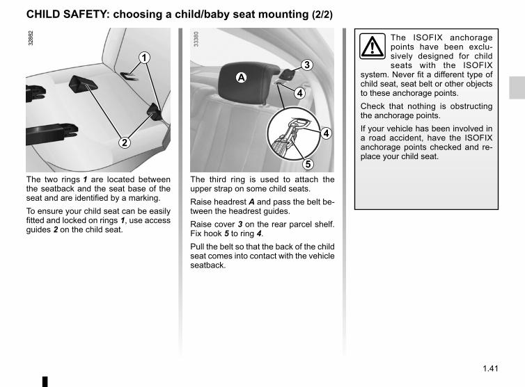
The ISOFIX anchorage points have been exclu-sively designed for child seats with the ISOFIX
system. Never fit a different type of child seat, seat belt or other objects to these anchorage points.Check that nothing is obstructing the anchorage points.If your vehicle has been involved in a road accident, have the ISOFIX anchorage points checked and re-place your child seat.
The third ring is used to attach the upper strap on some child seats.Raise headrest A and pass the belt be-tween the headrest guides.Raise cover 3 on the rear parcel shelf. Fix hook 5 to ring 4.Pull the belt so that the back of the child seat comes into contact with the vehicle seatback.
The two rings 1 are located between the seatback and the seat base of the seat and are identified by a marking.To ensure your child seat can be easily fitted and locked on rings 1, use access guides 2 on the child seat.
1
2
3
4
4
A
5

1.42
Some seats are not suitable for fitting child seats. The diagram on the follow-ing page shows you how to attach a child seat.The types of child seats indicated may not be available. Before using a differ-ent child seat, check with the manufac-turer that it can be fitted.
CHILD SAFETY: fitting a child seat (1/4)In the rear side seatA carrycot can be installed across the vehicle and will take up at least two seats. Position the child with his or her feet nearest the door.Move the front seat as far forward as possible to install a rear-facing child seat, then move back the seat in front as far as it will go, although without al-lowing it to come into contact with the child seat.For the safety of the child in the for-ward-facing seat, do not move the seat in front back past the middle of the runner, do not tilt the seatback too far (maximum of 25°) and raise the seat as much as possible.Check that the forward-facing child seat is resting against the back of the vehi-cle seat and that the headrest of the ve-hicle is not obstructing its use.
In the front seatThe laws concerning children travel-ling in the front passenger seat differ in every country. Consult the legislation in force and follow the indications on the diagram on the following page.Before fitting a child seat in this seat (if authorised):– lower the seat belt as far as possible;– move the seat as far back as possi-
ble;– gently tilt the seatback away from
vertical (approximately 25°);– on equipped vehicles, raise the seat
base as far as possible.Do not change these settings after the child seat is installed.
RISK OF DEATH OR SERIOUS INJURY: before installing a rear-facing child seat in this seat, check that
the airbag has been deactivated (refer to “Child safety: front passen-ger airbag deactivation/activation” Section 1).
Fit the child seat in a rear seat wherever possible.Check that when installing the child seat in the vehicle
it is not at risk of coming loose from its base.If you have to remove the headrest, check that it is correctly stored so that it does not come loose under harsh braking or impact.Always attach the child seat to the vehicle even if it is not in use so that it does not come loose under harsh braking or impact.
Make sure that the child seat or the child’s feet do not prevent the front seat from locking correctly. Refer
to the information on the “Front seat” in Section 1.

1.43
² Seat not suitable for fitting child seats.Child seat attached using the belt
¬Seat which allows a child seat with “Universal” approval to be at-tached by a seat belt.
−Seat which only allows a rear-facing standardised “Universal” seat to be installed using a seat belt.
³ Check the status of the air bag before fitting a child seat or allowing a passenger to use the seat.
RISK OF DEATH OR SERIOUS INJURY: Before fitting a rear-facing child seat on the front passenger
seat, check that the airbag has been deactivated (refer to the information on “Child safety: deactivating/acti-vating the front passenger airbag” at the end of the section).
Child seat attached using the ISOFIX mounting
ü Seat which allows an ISOFIX child seat to be fitted.
± The rear seats are fitted with an anchorage point which allows a forward-facing ISOFIX child seat with universal approval to be fitted. The an-chorage points are located in the lug-gage compartment and are visible.The size of the ISOFIX child seat is in-dicated by a letter:– A, B and B1: for forward-facing seats
in group 1 (9 to 18 kg);– C: rear-facing seats in group 1 (9 to
18 kg);– D and E: shell seat or rear-facing
seats in group 0 or 0+ (less than 13 kg);
– F and G: carrycots in group 0 (less than 10 kg).
Using a child safety system which is not approved for this vehicle will not correctly protect the baby or child. They risk serious or even fatal injury.
CHILD SAFETY: fitting a child seat (2/4)

1.44
CHILD SAFETY: fitting a child seat (3/4)The table below summarises the information already shown on the diagram on the previous page, to ensure the regula-tions in force are respected.
Type of child seat Weight of the child Seat size Front passenger
seat (1) (2) Rear side seats Rear centre seat
Carrycot fitted across the ve-hicleGroup 0
< 10 kg F, G X U - IL (3) U (3)
Rear-facing shell seatGroup 0 or 0+
< 13 kg and 9 to 18 kg E, D U U - IL (4) U (4)
rear-facing seatGroup 0+ and 1 9 to 18 kg C U U - IL (4) U (4)
Forward-facing seatGroup 1 9 to 18 kg A, B, B1 X U - IUF - IL (5) U (5)
Booster seatGroup 2 and 3
15 to 25 kg and 22 to 36 kg - X U (5) U (5)
(1) RISK OF DEATH OR SERIOUS INJURY: before installing a child seat on the front passenger seat, check that the airbag has been deactivated (refer to “Child safety: front passenger airbag deactivation/activation” Section 1).

1.45
X = Seat not suitable for fitting child seats.U = Seat which allows a child seat with “Universal” approval to be installed using a seat belt; check that it can be fitted.IUF/IL = On equipped vehicles, seat which allows an approved “Universal/semi-universal or vehicle specific” child seat to be at-
tached using the ISOFIX system; check that it can be fitted.(2) Only a rear-facing child seat can be fitted in this seat: raise the seat to the maximum and position it as far back as possible,
tilting the seatback slightly (approximately 25°).(3) A carrycot can be installed across the vehicle and will take up at least two seats. Position the child with his or her feet nearest
the door.(4) Move the front seat as far forward as possible to install a rear-facing child seat, then move back the seat in front as far as it will
go, although without allowing it to come into contact with the child seat.(5) Forward-facing child seat; position the seatback of the child seat in contact with the seatback of the vehicle seat. Adjust the
headrest, or remove it if necessary. Do not push the front seat more than halfway back on its runners and do not recline the seatback more than 25°.
CHILD SAFETY: fitting a child seat (4/4)

1.46
Deactivating the front passenger air bags(on equipped vehicles)You must deactivate certain devices in addition to the front passenger seat belt before fitting a child seat in the front passenger seat.
To deactivate the airbags: when the vehicle is stationary, push and turn lock 1 to position OFF.With the ignition on, you must check
that warning light 2 ¹ is lit on the central display and, depending on the vehicle, that the message “Passenger airbag off” is displayed.This light remains permanently lit to let you know that you can fit a child seat.
CHILD SAFETY: deactivating, activating the front passenger airbag (1/3)
1
The passenger air bag must only be deactivated or acti-vated with the ignition off.If it is interfered with when
the vehicle is being driven, indicator
lights å and © will come on.Switch the ignition off then on again to reset the air bag in accordance with the lock.
2

1.47
3
CHILD SAFETY: deactivating, activating the front passenger airbag (2/3)
A
A
The markings on the dashboard and labels A on each side of the passen-ger sun visor 3 (for example, the labels shown above) will remind you of these instructions.
A
DANGERSince front passenger airbag triggering and the position of a rear-facing
child seat are incompatible, NEVER use a restraining device for rear-facing children on a seat with an ACTIVATED AIRBAG in front of it. This provides a risk of DEATH or SERIOUS INJURY to the CHILD.

1.48
CHILD SAFETY: deactivating, activating the front passenger airbag (3/3)
Operating faultsIt is forbidden to fit a rear-facing child seat to the front passenger seat if the air bag activation/deactivation system is faulty.Allowing any other passenger to sit in that seat is not recommended.Contact your approved dealer as soon as possible.
Activating the front passenger air bagsYou should reactivate the air bag as soon as you remove the child seat from the front passenger seat to ensure the protection of the front passenger in the event of an impact.Reactivating the airbags: when the vehicle is stationary, push and turn lock 1 to position ON.With the ignition on, you must check
that the warning light 2 ¹ is off.
1
The passenger air bag must only be deactivated or acti-vated with the ignition off.If it is interfered with when
the vehicle is being driven, indicator
lights å and © will come on.Switch the ignition off then on again to reset the air bag in accordance with the lock.
2 DANGERSince front passenger airbag triggering and the position of a rear-facing
child seat are incompatible, NEVER use a restraining device for rear-facing children on a seat with an ACTIVATED AIRBAG in front of it. This provides a risk of DEATH or SERIOUS INJURY to the CHILD.

1.49
With the ignition on, the time and, depending on the vehicle, the exterior temperature are displayed.
Resetting the clock 1Vehicles equipped with a navigation system, radio, etc.Refer to the equipment instructions for the special features.
External temperature indicatorAs ice formation is related to climatic exposure, local
air humidity and temperature, the external temperature alone is not sufficient to detect ice.
CLOCK AND EXTERIOR TEMPERATUREExternal temperature indicatorSpecial note:When the outside temperature is – 3°C to + 3°C, the °C characters flash (sig-nalling a risk of ice on the road).
1

1.50
DRIVING POSITION: LEFT-HAND DRIVE (1/2)
1 2 3 4 5 6 8 9 10 11
121314
16
21
19
15
7
17
20
25 2224 2326
18

1.51
DRIVING POSITION: LEFT-HAND DRIVE (2/2)The equipment fitted, described below, DEPENDS ON THE VERSION AND COUNTRY.
1 Side air vent.2 Side window demister outlet.3 Stalk for:
– direction indicator lights,– exterior lights,– front fog lights,– rear fog light.
4 Instrument panel.5 Driver’s air bag and horn location.6 – Windscreen wiper/washer stalk,
– Trip computer information read-out control and vehicle settings personalisation menu.
7 – Display (depending on the vehi-cle) of time, temperature, radio information, navigation system in-formation, etc.
– Driver and front passenger seat belt unfastened and passenger airbag deactivated warning lights.
8 Centre air vents.9 Location for passenger air bag.10 Side window demister outlet.11 Side air vent.12 Glove box.13 Air-conditioning control.14 Location for radio, navigation
system, etc.15 Cigarette lighter.16 Gearstick.17 Multimedia control.18 Cruise control/speed limiter control.19 Handbrake.
20 Audio connection socket.21 Central door locking/unlocking con-
trols and hazard warning lights switch.
22 Key ignition switch23 Cruise control/speed limiter controls24 Control for adjusting steering wheel
height.25 Bonnet release control.26 Controls for:
– headlight beam height remote ad-justment;
– lighting dimmer for control instru-ments;
– activation/deactivation of the trac-tion control system.

1.52
DRIVING POSITION: RIGHT-HAND DRIVE (1/2)
2 3 7 8
18
11
23
6 10
1617 122621
9
25 14
54
15
1
22
20
1324
19

1.53
DRIVING POSITION: RIGHT-HAND DRIVE (2/2)The equipment fitted, described below, DEPENDS ON THE VERSION AND COUNTRY.
1 Side air vent.2 Side window demister outlet.3 Location for passenger air bag.4 – Display (depending on the vehi-
cle) of time, temperature, radio information, navigation system in-formation, etc.
– Driver and front passenger seat belt unfastened and passenger airbag deactivated warning lights.
5 Centre air vents.6 Stalk:
– direction indicator lights,– exterior lights,– front fog lights,– rear fog light.
7 Location for driver’s air bag and horn.
8 Instrument panel.
9 – Windscreen wiper/washer stalk,– Trip computer information read-
out control and vehicle settings personalisation menu.
10 Side window demister outlet.11 Side air vent.12 Controls for:
– headlight beam height remote ad-justment;
– lighting dimmer for control instru-ments;
– activation/deactivation of the trac-tion control system.
13 Key ignition switch.14 Cruise control/speed limiter controls.
15 Control for adjusting steering wheel height.
16 Central door locking/unlocking con-trols and hazard warning lights switch.
17 Location for radio, navigation system, etc.
18 Multimedia control.19 Cruise control/speed limiter control.20 Handbrake.21 Gearstick.22 Audio connection socket.23 Cigarette lighter.24 Air-conditioning control.25 Glove box.26 Bonnet release control.

1.54
Instrument panel A: lights up when the headlamps are switched on. The brightness can be adjusted by turning the control knob 1.In some cases, the appearance of a warning light is accompanied by a mes-sage.
WARNING LIGHTS (1/3)
The © warning light means you should drive very carefully to an approved dealer as soon as pos-sible. If you fail to follow this recom-mendation, you risk damaging your vehicle.
A
å Air bag warning lightThis comes on when the igni-
tion is switched on and goes out after a few seconds.If it does not light up when the ignition is switched on, or if it lights up when the engine is running, it indicates a fault in the system.Contact your approved Dealer as soon as possible.
� Vehicle ready for driving warning light
This comes on when the engine is started.
ð Not used
u Side light tell-tale light
á Main beam headlight tell-tale light
k Dipped beam headlight tell-tale light
g Front fog light tell-tale light
f Rear fog light tell-tale light
c Left-hand direction indicator tell-tale light
b Right-hand direction indica-tor tell-tale light
2 Door status warning lightIf it lights up with the ignition on, a
door or the tailgate is open or not prop-erly closed.
If no lights or sounds are ap-parent, this indicates a fault in the instrument panel. This indicates that it is essential
to stop immediately (as soon as traf-fic conditions allow). Ensure that the vehicle is correctly immobilised and contact an approved Dealer.
Warning light ® re-quires you to stop immedi-ately, for your own safety,
as soon as traffic conditions allow. Switch off the engine and do not re-start it. Contact an approved Dealer.
1
The presence and operation of the warning lights DEPEND ON THE EQUIPMENT AND COUNTRY.

1.55
WARNING LIGHTS (2/3)
®STOP lightThis lights up when the ignition
is switched on and goes out as soon as the engine is started. It comes on with other warning lights and/or messages, and is accompanied by a beep.It requires you to stop immediately, for your own safety, as soon as traffic con-ditions allow. Switch off the engine and do not restart it.Contact an approved Dealer.
D Brake circuit fault warning light
If it comes on during braking and is ac-companied by the ® warning light and a beep, it indicates that the fluid level in the circuit is low or that there is a braking system fault. Stop as soon as traffic conditions allow and contact an approved Dealer.
Ú 12 V battery charge warning light
If it comes on together with the ® warning light and a beep, it indicates that the electrical circuit is overcharged or undercharged.
©Warning lightThis lights up when the ignition
is switched on and goes out as soon as the engine is started. It can light up in conjunction with other warning lights and/or messages on the instrument panel.It means you should drive very care-fully to an approved dealer as soon as possible. If you fail to follow this recom-mendation, you risk damaging your ve-hicle.
The presence and operation of the warning lights DEPEND ON THE EQUIPMENT AND COUNTRY.
ß Front seat belt reminder warning light
It lights up on the central display when the engine is started and, if the driv-er’s seat belt is not fastened, the light flashes and a beep sounds for about two minutes when the vehicle reaches a speed of approximately 12 mph (20 km/h).
Î Ï Cruise control and speed limiter indica-
tor lightsRefer to the information on “Cruise con-trol/speed limiter” in Section 2.
� Charging cord plugged in warning light
This comes on when the charging cord is plugged into the vehicle.
A

1.56
� Electrotechnical system warning light
When the blue warning light comes on, this means that the traction battery tem-perature is too low.When the orange warning light comes on, this means the traction battery or the motor temperature is too high. Opt for a calmer driving style.If either of these warning lights come on, this may lead to reduced vehicle performance.
� Low traction battery level warning light
This comes on when the traction bat-tery charge level has reached the re-serve threshold. Please see the infor-mation on “Displays and indicators” in Section 1.
WARNING LIGHTS (3/3)
� Electrotechnical system warning light
If it lights up while driving, this means there is an electrotechnical fault in the “400 Volt” electrical circuit. Please see an authorised dealer as soon as pos-sible.
ù Electronic Stability Program and traction control system
warning lightThere are several reasons for the warn-ing light coming on: please refer to the information on “Driver correction de-vices and aids” in Section 2.
x Anti-lock braking warning light
This lights up when the ignition is switched on and goes out after a few seconds.If it does not go out after the ignition is switched on, or lights up when driving, there is a fault with the ABS. Braking will then be as normal, without the ABS. Contact an approved Dealer as soon as possible.
The presence and operation of the warning lights DEPEND ON THE EQUIPMENT AND COUNTRY.
A

1.57
DISPLAYS AND INDICATORS (1/2)
Charge level 2The gauge indicates the level of energy remaining.
Reserve level 1This indicates that the battery is at ap-proximately 12% charge. Warning light � comes on, along with a beep.To optimise your range, please see the information on “Recommendations: saving energy” in Section 2.
Imminent immobilisation level 3This indicates that the battery is at less than 6% charge. A beep is repeated every 20 seconds and warning light � flashes. The message “Limited performance” is displayed on the instru-ment panel.Motor performance gradually de-creases until the vehicle comes to a stop.Please see the information on “Towing: in the event of energy loss” in Section 5.
The presence and operation of the display and indicators DEPENDS ON THE LEVEL OF EQUIPMENT AND THE COUNTRY.
Speedometer 4Vehicle speed is limited to approxi-mately 80 mph (135 km/h).
43
1
2

1.58
DISPLAYS AND INDICATORS (2/2)
Multifunction display 5Please refer to the information on the “Trip computer: general information” in Section 1.
The presence and operation of the display and indicators DEPENDS ON THE LEVEL OF EQUIPMENT AND THE COUNTRY.
Charge meter 6Please refer to the information on the “Charge meter” in Section 2.
“Energy recovery” usage zone AThe needle tells you that the vehicle is generating energy and the traction bat-tery is being recharged (under braking or going downhill).
A CB
6
5 Position B “neutral”The needle tells you that you are at nil consumption (the vehicle is at a stand-still without consuming energy).
“Consumption” usage range CThe needle tells you the energy con-sumption (vehicle moving on a flat sur-face, for example).
6

1.59
TRIP COMPUTER: general information (1/2)
Trip computer 1Depending on the vehicle, this includes the following functions:– distance travelled;– journey parameters;– information messages;– operating fault messages (con-
nected to the warning light ©);– warning messages (connected to the ® warning light);
– vehicle settings customisation menu.All these functions are described on the following pages.
Display selection keys 2 and 3Scroll through the following information upwards (key 2) or downwards (key 3) by pressing briefly and successively (the display depends on the vehicle equipment and country).a) total mileage and trip mileage re-
corder;
b) journey parameters:– total energy consumption since
the last reset;– average energy consumption;– current energy consumption;– total energy consumption since
the vehicle first entered into serv-ice;
– estimated range;– distance travelled;– average speed.
c) mileage before service;e) vehicle settings customisation menu;f) trip log, operating faults and informa-
tion message readout.
3
2
1

1.60
TRIP COMPUTER: general information (2/2)
Trip mileage resettingWith “trip mileage recorder” selected on the display, press button 2 or 3 until the mileage recorder resets to zero.
Resetting the journey parameters (reset button)with the display showing one of the journey parameters, press button 2 or 3 until the display is reset.
Reading energy consumption valuesSome vehicle equipment items con-sume energy: the energy consumed by the vehicle may therefore differ from the energy consumed on the electric counter.
Interpreting some of the values displayed after resettingThe values showing average energy consumption and average speed will become more stable and reliable the further you have travelled since the last time the Reset button was pressed.
Automatic resetting of the journey parametersResetting occurs automatically when the maximum value of any of the pa-rameters is exceeded.
3
2

1.61
TRIP COMPUTER AND WARNING SYSTEM: journey parameters (1/4)
Examples of selections Interpreting the display selected
a) Total mileage and trip mileage recorder.101778 km
112.4 km
Consumptionb) Journey parameters.
Energy consumed since the last reset.20 kWh
AverageAverage energy consumption since the last reset.The value is displayed after having travelled at least 400 metres since the last reset. 18,5 kWh/100km
Current energy consumption.
The display of information shown below DEPENDS ON THE VEHICLE EQUIPMENT AND COUNTRY.

1.62
TRIP COMPUTER AND WARNING SYSTEM: journey parameters (2/4)
Examples of selections Interpreting the display selected
Range Estimated range with remaining energy.Value estimated based on average energy usage over the last 125 miles (200 km).118 km
Distance
Distance travelled since the last reset.522 km
AverageAverage speed since the last reset.The value is displayed after driving 400 metres.
48 km/h
Consumption
Total energy usage since vehicle first entered service.487 kWh
The display of information shown below DEPENDS ON THE VEHICLE EQUIPMENT AND COUNTRY.
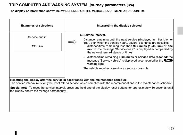
1.63
TRIP COMPUTER AND WARNING SYSTEM: journey parameters (3/4)
Examples of selections Interpreting the display selected
Service due inc) Service interval.
Distance remaining until the next service (displayed in miles/kilome-tres), then when the service nears, several scenarios are possible:– distance/time remaining less than 900 miles (1,500 km) or one
month: the message “Service due in” is displayed accompanied by the nearest term (distance or time);
– distance/time remaining 0 km/miles or service date reached: the message “Service vehicle” is displayed accompanied by the © warning light.
The vehicle requires a service as soon as possible.
1936 km
Resetting the display after the service in accordance with the maintenance schedule.The service interval must only be reset after a service which complies with the recommendations in the maintenance schedule.Special note: To reset the service interval, press and hold one of the display reset buttons for approximately 10 seconds until the display shows the mileage permanently.
The display of information shown below DEPENDS ON THE VEHICLE EQUIPMENT AND COUNTRY.

1.64
TRIP COMPUTER AND WARNING SYSTEM: journey parameters (4/4)The display of information shown below DEPENDS ON THE VEHICLE EQUIPMENT AND COUNTRY.
Examples of selections Interpreting the display selected
d) Vehicle settings customisation menu.Enables certain vehicle functions to be set (instrument panel language, parking distance control, etc.). Refer to the information on “Vehicle set-tings customisation menu” in Section 1.
SETTINGS MENUpress and hold
Speed limiter
e) Cruise control/speed limiter programmed speed.Refer to the information on the “Speed limiter” and “Cruise control” in Section 2.
90 km/h
Cruise control
90 km/h
No message available
f) Trip log.Successive display:– information messages (passenger airbag OFF etc);– operating fault messages.

1.65
TRIP COMPUTER AND WARNING SYSTEM: information messages
Examples of messages Interpreting the display selected
“Charge remain. 02:10" Indicates the time remaining before a full charge.
“Checking control functions” Displayed with the ignition on when the vehicle is running self-diagnostics.
“Traction control off” Indicates that you have deactivated the ASR function.
“No message available” No warning is stored.
“Steering wheel not locked” Indicates that the steering column has not been locked.
“Performance limited” Indicates deterioration of vehicle performance.
“Brake the vehicle” Follow these instructions: risk of damage to the motor.
These can help in the vehicle starting phase, or give information about a selection or a driving status.Examples of information messages are given in the following pages.

1.66
TRIP COMPUTER AND WARNING SYSTEM: operating fault messages
These appear with the © warning light and mean that you should drive very carefully to an authorised dealer as soon as possible. If you fail to follow this recommendation, you risk damaging your vehicle.They disappear when the display selection key is pressed or after several seconds and are stored in the computer log. The © warning light stays on. Examples of operating fault messages are given in the following pages.
Examples of messages Interpreting the display selected
« Check airbag » Indicates a fault in the restraint system in addition to the seat belts. In the event of an accident, it is possible that they may not be triggered.
« Elec. System to check » Indicates a fault on one of the pedal sensors or in the 12 V battery management system.
« Check braking system » Indicates wear or the need to check the braking system.
« Service required » Indicates that the system linked to the fast traction battery replacement should be checked.
« Elec. System to check » Indicates a fault in the traction system.
« Battery charge impossible » Indicates a fault on the traction battery recharge system.

1.67
TRIP COMPUTER AND WARNING SYSTEM: warning message
These appear with the ® warning light and require you to stop immediately, for your own safety, as soon as traffic conditions allow. Stop your engine and do not restart it. Contact an approved Dealer.Examples of warning messages are given in the following pages. Note: the messages appear on the display either individually or alternately (when there are several messages to be displayed), and may be accompanied by a warning light and/or a beep.
Examples of messages Interpreting the display selected
“Braking system fault” Indicates a fault in the braking system.
« Power steering fault » Indicates a fault in the steering.
« Electrical motor fault » Indicates that the vehicle is losing power.
« Electrical fault danger » Indicates a fault in the electric system.

1.68
VEHICLE SETTINGS CUSTOMISATION MENU
Adjusting the settingsPress button 2 or 3 to select a function to change:a) Auto door locking while driving ;b) Auto dipped-beam headlights ;c) Rear parking sensor ;d) Parking sensor volume ;e) LANGUAGE.
= function activated
< function deactivated
On equipped vehicles, this function, which is integrated in the trip compu-ter 1, allows you to activate/deactivate some of the vehicle’s functions.
Accessing the settings customisation menuWith the vehicle stopped, press button 2 or 3 several times until the message “Settings menu: press and hold” is shown on display 1. Press either button 2 or 3 for longer than 2 seconds to enter the menu.
Once a line has been selected, keep pressing button 2 or 3 to change the function: If you select either “Parking sensor volume” or “LANGUAGE”, you will have to make a further selection (sound volume of the parking distance control or instrument panel language). In this case, make your selection and confirm it by holding either button 2 or 3, the value selected is shown by a
~ in front of the line.To exit the menu, select “EXIT” or “BACK” then confirm by keeping either button 2 or 3 pressed. It may be nec-essary to carry out this operation more than once.
2
3
1
The vehicle settings personalisation menu cannot be used when driving. The display automatically switches back to trip computer mode.

1.69
REAR-VIEW MIRRORS
Door mirrorsAdjustmentSelect the door mirror using switch 2, then use button 1 to adjust it to the de-sired position.
Heated door mirrors(depending on the vehicle)Mirror de-icing is carried out at the same time as rear screen de-icing.
The driver’s door mirror may have two clearly de-fined zones. Zone B shows what can normally be seen
in an ordinary rear-view mirror. Zone A increases rear side visibility.The objects in zone A look much further away than they really are.
1
A B
2
3
Interior rear view mirrorIts position can be adjusted.
Rear view mirror with lever 3For night driving, to avoid being dazzled by the headlights of the car behind you, flip the small lever 3 located behind the rear view mirror.
Rear view mirror without lever 3The rear view mirror darkens automati-cally at night if you are being followed by a vehicle with its lights on.

1.70
AUDIBLE AND VISUAL SIGNALS
HornPress on the sides of the steering wheel boss A.
Headlight flasherPull stalk 1 towards you to flash the headlights.
é Hazard warning lightsPress switch 2. This switch il-
luminates all four direction indicators and the side-mounted indicator lights simultaneously. It must only be used in an emergency to warn drivers of other vehicles that you have had to stop in an area where stopping is prohibited or unexpected or that you are obliged to drive under special conditions.Depending on the vehicle, the hazard warning lights may come on automati-cally under heavy deceleration. You can switch them off by pressing switch 2.
Direction indicatorsMove stalk 1 parallel to the steering wheel and in the direction you are going to turn it.When driving on the motorway, the steering wheel is not often turned enough to return the stalk automatically to 0. There is an intermediate position in which the switch may be held when changing lanes.When the stalk is released, it automati-cally returns to 0.
A
2
1
0

1.71
á Main beam headlights
With the dipped beam headlights lit, pull stalk 1 towards you. This indicator light on the instrument panel comes on.To return to the dipped headlight posi-tion, pull the stalk 1 towards you again.
Before driving at night: check the electrical equip-ment is operating correctly and adjust your headlights
(if your vehicle is not carrying its normal load). As a general precau-tion, check that the lights are not obscured (by dirt, mud, snow or ob-jects being transported).
EXTERIOR LIGHTING AND SIGNALS (1/3)
31
u Side lightsTurn the ring 2 until the symbol
is opposite mark 3.
k Dipped beam headlights
Manual operationTurn the ring 2 until the symbol is oppo-site mark 3. This indicator light on the instrument panel comes on.
Automatic operationTurn ring 2 until the AUTO symbol is op-posite mark 3: with the engine running, the dipped beam headlights switch on or off automatically depending on the brightness of the light outside, without any action on stalk 1.
2

1.72
EXTERIOR LIGHTING AND SIGNALS (2/3)
Switching off the lightsThere are two possibilities:– manually, move ring 2 to position 0;– the lights will go out automatically
when the engine is switched off, the driver’s door is opened or the vehicle is locked. In this case, the next time the engine is started the lights will be switched back on according to the position of the ring 2.
NB: if the fog lights are lit, the lights are not switched off automatically.
“See-me-home lighting” functionDepending on the vehicle, this func-tion allows you to briefly switch on the dipped beam headlights (to provide light when opening a gate, etc.).With the engine and lights off and ring 2 in the 0 position, pull stalk 1 to-wards you: the dipped beam head-lights light up for approximately thirty seconds. To increase this duration, you may pull the stalk up to four times (total time restricted to two minutes). Depending on the vehicle, the message “See-me-home _ _ _” accompanied by the lighting time is displayed on the in-strument panel to confirm the action.To switch off the lights before they go out automatically, turn ring 2 to any po-sition, then return it to position 0.
Lights-on reminder buzzerIf the lights are on after the engine is switched off, a warning beep sounds when the driver’s door is opened to warn you that the lights are still on.
1 2

1.73
EXTERIOR LIGHTING AND SIGNALS (3/3)
When driving in fog or snow, or when transporting objects which are higher than the roof, the headlights do not come on automatically.The driver remains in full control of switching on the fog lights: the indi-cator lights on the instrument panel inform you whether the fog lights are lit (indicator light on) or not (indi-cator light off).
f Rear fog lightTurn centre ring 4 on the stalk
until the symbol faces mark 5, then re-lease it.Operation of the fog lights depends on the exterior lighting selected, and an in-dicator light will light up on the instru-ment panel.To avoid inconveniencing other road users, remember to switch off the rear fog light when it is no longer needed.
Turning off the fog lightsTurn ring 4 again until mark 5 is oppo-site the symbol for the fog light you wish to switch off. The corresponding indi-cator light goes out on the instrument panel.The front and rear fog lights switch off when the exterior lights are switched off.
1 4 5
g Front fog lightsTurn centre ring 4 on the
stalk 1 until the symbol faces mark 5, then release it.Operation of the fog lights depends on the exterior lighting position selected, and an indicator light will light up on the instrument panel.

1.74
On vehicles fitted with this function, control A allows you to adjust the height of the beams according to the load.Turn control A downwards to lower the headlights and upwards to raise them.For vehicles not fitted with control A, adjustment is automatic.
ELECTRICAL ADJUSTMENT OF THE DIPPED BEAM HEADLIGHTS
A
For manual settingExamples of positions for adjusting
control A according to the load.
Driver alone or with front passenger 0
Driver with one front passenger and one rear passenger 0
Driver with one front passenger and two or three rear passengers
1
Driver with one front passenger, three rear passengers and luggage
3

1.75
Vehicle fitted with front windscreen wiper rain sensor
A park
B automatic wiper function.When this position is selected, the system detects water on the wind-screen and triggers the wipers at a suitable wiping speed. It is possi-ble to change the triggering thresh-old and the time sweeps by turning ring 2:
– E : minimum sensitivity– F : maximum sensitivityNB: in foggy weather or during snowfalls, the wiping is not automati-cally triggered and remains under the driver’s control.
C normal wiping speed
D fast wiping speed
Special noteWhen driving the vehicle, the wiping speed slows down whenever the ve-hicle stops. For example, fast wiping speed will slow to normal wiping speed. As soon as the vehicle moves off, wiping will return to the speed originally selected.If stalk 1 is operated, it overrides and cancels the automatic function.
Vehicle fitted with intermittent windscreen wipers
A park
B intermittent wipingThe wipers will pause for several seconds between sweeps. It is possible to change the time be-tween sweeps by turning ring 2.
C normal wiping speed
D fast wiping speed
WINDSCREEN WASH/WIPE (1/2)
1 1
ABC
D
E
F2
For all vehicles, position C can be accessed with the ignition on and positions B and D can only be ac-cessed with the engine running.

1.76
Windscreen washerWith the ignition on, pull stalk 1 then release.A brief pull will trigger a single sweep of the wipers, in addition to the wind-screen washer.A longer pull will trigger three sweeps of the wipers followed, a few seconds later, by a fourth, in addition to the wind-screen washer.
WINDSCREEN WASH/WIPE (2/2)
1
In freezing or snowy weather, ensure they are not stuck to the windscreen (including the central area located behind the interior rear-view mirror) and the rear screen before starting the wipers (risk of motor overheat-ing).
1
A
When working in the engine compartment, ensure that the windscreen wiper stalk is in position A (off).
Risk of injury.
Before any action on the windscreen (washing the vehicle, de-icing, cleaning the windscreen, etc.) return
stalk 1 to position A (off).Risk of injury and/or damage.
2.1
Section 2: Driving(Advice on use relating to fuel economy and the environment)
Starting, stopping the engine . . . . . . . . . . . . . . . . . . . . . . . . . . . . . . . . . . . . . . . . . . . . . . . . . . . . . . . 2.2Gear control . . . . . . . . . . . . . . . . . . . . . . . . . . . . . . . . . . . . . . . . . . . . . . . . . . . . . . . . . . . . . . . . . . . . 2.3Handbrake . . . . . . . . . . . . . . . . . . . . . . . . . . . . . . . . . . . . . . . . . . . . . . . . . . . . . . . . . . . . . . . . . . . . . 2.4Vehicle range: recommendations . . . . . . . . . . . . . . . . . . . . . . . . . . . . . . . . . . . . . . . . . . . . . . . . . . . 2.5Environment . . . . . . . . . . . . . . . . . . . . . . . . . . . . . . . . . . . . . . . . . . . . . . . . . . . . . . . . . . . . . . . . . . . 2.7Charge meter. . . . . . . . . . . . . . . . . . . . . . . . . . . . . . . . . . . . . . . . . . . . . . . . . . . . . . . . . . . . . . . . . . . 2.8Driving correction devices . . . . . . . . . . . . . . . . . . . . . . . . . . . . . . . . . . . . . . . . . . . . . . . . . . . . . . . . . 2.9Speed limiter . . . . . . . . . . . . . . . . . . . . . . . . . . . . . . . . . . . . . . . . . . . . . . . . . . . . . . . . . . . . . . . . . . . 2.13Cruise control . . . . . . . . . . . . . . . . . . . . . . . . . . . . . . . . . . . . . . . . . . . . . . . . . . . . . . . . . . . . . . . . . . 2.16Parking distance control . . . . . . . . . . . . . . . . . . . . . . . . . . . . . . . . . . . . . . . . . . . . . . . . . . . . . . . . . . 2.20

2.2
Start position DStarting the engine– Move the gear lever to position P
only ;– turn the key to position D and re-
lease it.
Warning light � may flash on the in-strument panel, along with a beep. As soon as light � stops flashing and the beep stops, the vehicle is ready to drive.
“Stop and steering lock” position StTo unlock: turn the key and the steering wheel slightly.To lock: remove the key and turn the steering wheel until the steering column locks.
“Accessories” position AWhen the ignition is switched off, any accessories (radio, etc.) will continue to function.
“On” position MThe ignition is switched on:
STARTING, STOPPING THE ENGINE
Driver’s responsibilityNever leave your vehi-cle with the key inside and never leave a child (or a
pet) unsupervised, even for a short while.There is a risk that they could start the engine or operate electrical equipment (electric windows etc.) and trap part of their body (neck, arms, hands, etc.).Risk of serious injury.Never switch off the ignition before the vehicle has stopped completely. Once the engine has stopped, the brake servo, power-assisted steer-ing, etc., and the passive safety de-vices such as the airbags and pre-tensioners will no longer operate.
The vehicle can only be started if the charging cord is unplugged from the vehicle.The vehicle can only be started if the selection lever is at P. Please see the information on “Gear con-trol” in Section 2.
Stopping the engineBring the key to “Stop” position. Warning light � goes out.

2.3
DrivingPut lever 1 in position D.The vehicle moves forward once you release the brake pedal (without press-ing on the accelerator pedal).While driving, press the accelerator pedal to achieve the desired speed.
ReversePut lever 1 in position R.The reversing lights will come on as soon as reverse gear is selected (with the ignition on).
GEAR CONTROL (1/2)
3
2
14
56
7
8
Operates similar to an automatic gear-box.
Selector lever 1The display 3 on the instrument panel indicates the gear lever position.4: P: park5: R: reverse gear6 : N : neutral7 : D : forward8 : display of gear lever position
OperationWith your foot on the brake pedal, the selection lever 1 in P, switch on the ig-nition.Start the motor.To move out of position P, you must de-press the brake pedal before pressing unlocking button 2.With the foot on the brake pedal (warn-ing light c on the display 3 goes out), move the lever out of position P.Only engage D or R when the vehi-cle is stopped, with your foot on the brake and the accelerator pedal re-leased.
The vehicle can only start of the gear selector is in position P.The vehicle can only be started if the charging cord is unplugged from the vehicle.

2.4
Parking the vehicleWhen the vehicle is at a standstill, place the lever in position P: the drive wheels are mechanically locked by the transmission.Apply the handbrake.
GEAR CONTROL (2/2)/HANDBRAKE
When setting off, if the lever is locked in position P even though you are de-pressing the brake pedal and pressing unlocking button 2, the lever can be re-leased manually. To do this, press the button by inserting an object into the hole 10 and simultaneously press un-locking button 2 located on the lever.
10
2
In the event an impact to the underside of the vehicle (e.g.: striking a post, raised kerb or other street furni-
ture) this may result in damage to the vehicle (e.g.: twisted axle), the electrical circuit or the traction bat-tery.Do not touch the circuit elements or any fluids or liquids.To prevent any risk of accident, have your vehicle checked by an authorised dealer.Risk of serious injury or electric shock and risk to life.
HandbrakeTo release:Pull the lever 11 up slightly, press button 12 and then lower the lever to the floor.
To apply:Pull lever 11 upwards and make sure the vehicle is immobilised.
When stationary and de-pending on the slope and/or vehicle load, it may be nec-essary to pull up the hand-
brake at least two extra notches and engage position P.
Make sure that the hand-brake is properly released when driving (red indicator light off), otherwise over-
heating may occur.
12
11

2.5
VEHICLE RANGE: recommendations (1/2)The vehicle range is approved for a mixed NEDC cycle (New European Driving Cycle).In real usage, the range of an electric vehicle may vary depending on several factors over which you have partial con-trol, which may make a considerable difference to the vehicle range. These factors are:– speed and driving style;– type of road;– heating level;– tyres;– vehicle loading.
Speed and driving styleHigh speeds will reduce your vehicle’s range.A “sporty” driving style reduces your vehicle range: opt for a “lighter” driving style.Drive at a constant speed.Adapt your driving to avoid exces-sive energy consumption. Please refer to the “Charge meter” information in Section 2.
Anticipate traffic changes by lifting your foot off the accelerator pedal in order to recover energy. Please refer to the “Charge meter” information in Section 2.
Road typeDo not try to maintain the same speed up a hill, accelerate no more than you would on the level. Keep your foot in the same position on the accelerator pedal.

2.6
VEHICLE RANGE: recommendations (2/2)
Heating levelsThe use of heating or air-conditioning reduces vehicle range.Before using the vehicle, you are rec-ommended to favour “programmable heating” mode to help maintain the ve-hicle’s optimum range (please refer to the information on “Air-conditioning: programming” in Section 3).Keep your usage of heating or air-con-ditioning down to a minimum while driv-ing. Favour ECO mode - please see the information on “Automatic air-condition-ing” in Section 3.
TyresAn under-inflated tyre increases energy consumption. Comply with the speci-fied tyre pressures for your vehicle.When driving, use tyres made by the same manufacturer, with the same di-mensions, type and structure as the original tyres. The use of non-regula-tion tyres significantly reduces vehicle range.Please see the information on “Tyre pressure” in Section 4.
Vehicle loadingAvoid pointlessly overloading your ve-hicle.

2.7
ENVIRONMENTEmissionsYour vehicle has been designed to emit fewer greenhouse gases (CO2) while in use, and therefore to consume less fuel (eg. 140 g/km, equivalent to 5.3 l/100 km for a diesel vehicle).Our vehicles are also equipped with a particle filter system including a cata-lytic converter, an oxygen sensor and an active carbon filter (the latter pre-vents vapour from the fuel tank being released into the open air).For certain diesel vehicles, this system also has a particle filter to reduce the volume of soot particles emitted.
Please make your own contribution towards protecting the environment too– Worn parts replaced in the course of
routine vehicle maintenance (vehi-cle battery, oil filter, air filter, batter-ies, etc.) and oil containers (empty or filled with used oil) must be disposed of through specialist organisations.
– At the end of the vehicle’s service life, it should be sent to approved centres to ensure that it is recycled.
– In all cases, comply with local legis-lation.
RecyclingYour vehicle is 85% recyclable and 95% recoverable.To achieve these objectives, many of the vehicle components have been de-signed to enable them to be recycled. The materials and structures have been carefully designed to allow these components to be easily removed and reprocessed by specialist companies.In order to preserve raw material re-sources, this vehicle incorporates nu-merous parts made from recycled plas-tics or renewable materials (vegetable or animal-derived materials such as cotton or wool).
Your vehicle has been designed with respect for the environment in mind for its entire service life: during production, use and at the end of its life.This commitment is illustrated by the of the manufacturer eco² signature.
ManufactureYour vehicle has been manufactured at a factory which complies with a policy to reduce the environmental impact on the surrounding areas (reduction of water and energy consumption, visual and noise pollution, atmospheric emis-sions and waste water; sorting and re-using waste).

2.8
CHARGE METER
A
BC
D
A CD
The traction battery supplies the elec-trical energy required for the motor to move the vehicle.When you lift your foot off the accelera-tor pedal, the motor generates electri-cal current during deceleration, and this energy is used to recharge the traction battery.
“Energy recovery” usage zone AIndicates that the vehicle is generating energy and recharging the battery.
Energy recovery featuresThe motor generates a more significant engine brake than a conventional vehi-cle.After a maximum charge for the traction battery and during the first few miles when driving the vehicle, the engine brake is temporarily reduced. Please adapt your driving style appropriately.
Position B “neutral”Indicates nil consumption.
“Recommended consumption” usage zone CIndicates “economical” energy con-sumption.
“Consumption not recommended” usage zone DIndicates high energy consumption.

2.9
ABS (anti-lock braking system)Under heavy braking, the ABS prevents the wheels from locking, allowing the stopping distance to be managed and keeping control of the vehicle.Under these circumstances, the vehi-cle can be steered to avoid an obstacle whilst braking. In addition, this system can increase stopping distances, par-ticularly on roads with low surface grip (wet ground etc.).You will feel a pulsation through the brake pedal each time the system is activated. The ABS does not in any way improve the vehicle’s physical perform-ance relating to the road surface and roadholding. It is still essential to follow the rules of good driving practice (such as driving at a safe distance from the vehicle in front etc.).
These include:– the ABS (anti-lock braking
system);– the electronic stability program
ESP with understeer control and traction control ASR;
– emergency brake assist with, de-pending on the vehicle, braking anticipation.
In an emergency, apply firm and continuous pressure to the brake pedal. There is no need to pump it repeatedly. The ABS will modu-late the force applied in the braking system.
These functions are an ad-ditional aid in the event of critical driving conditions, enabling the vehicle behav-
iour to be adapted to suit the driving conditions.However, the functions do not take the place of the driver. They do not increase the vehicle’s limits and should not encourage you to drive more quickly. Therefore, they can under no circumstances replace the vigilance or responsibil-ity of the driver when manoeuvring the vehicle (the driver must always be ready for sudden incidents which may occur when driving).
Your braking systems are partially operational. However, it is dangerous to brake suddenly and
it is essential to stop immediately, as soon as traffic conditions allow. Contact an approved dealer.
Operating faults:
– © and x lit up on the in-strument panel alongside, depend-ing on the vehicle, messages “Check ABS”, “Check braking system” and “Check ESP”: ABS, ESP and emer-gency brake assist are deactivated. Braking is always enabled;
– x, D, © and ® lit up on the instrument panel alongside the message “Braking system fault”: this indicates a fault in the braking system.
In both cases, consult an approved Dealer.
DRIVER CORRECTION DEVICES/AIDS (1/4)
2.10
Electronic stability program ESP with understeer control and traction control ASRElectronic stability program ESPThis system helps you to keep control of the vehicle in critical driving condi-tions (avoiding an obstacle, loss of grip on a bend, etc.).
Operating principleA sensor in the steering wheel detects the direction selected by the driver.Other sensors throughout the vehicle measure the actual direction.The system compares driver input to the actual trajectory of the vehicle and corrects the trajectory if necessary by controlling the braking of certain wheels and/or engine power. In the event that the system is engaged, indicator light
ù flashes on the instrument panel.
Understeer controlThis system optimises the action of the ESP in the case of pronounced unders-teering (loss of front axle road holding).
Traction control ASRThis system helps to limit wheelspin of the drive wheels and to control the ve-hicle when pulling away accelerating or decelerating.Operating principleUsing the wheel sensors, the system measures and compares the speed of the drive wheels at all times and slows down their over-rotation. If a wheel is starting to slip, the system brakes au-tomatically until the drive supplied be-comes compatible with the level of grip under the wheel again.
Operating faultsWhen the system detects an operat-ing fault the message “Check ESP” and warning light © appear on the in-strument panel. In this case, the ESP and ASR are deactivated.Consult an approved dealer.
DRIVER CORRECTION DEVICES/AIDS (2/4)

2.11
The traction control ASR offers addi-tional safety, it is recommended that you do not drive with the function disa-bled. Correct this as soon as possible by pressing switch 1 again.NB: the function is reactivated auto-matically when the ignition is switched on or when a speed of approximately 24 mph (40 km/h) is exceeded.
Emergency brake assistThis system supplements the ABS and helps reduce vehicle stopping dis-tances.
Operating principleThe system is for detecting an emer-gency braking situation. In this case, the braking assistance immediately de-velops maximum power and may trig-ger ABS regulation.ABS braking is maintained as long as the brake pedal is applied.
Hazard warning lights switching onThese may light up in the event of rapid deceleration.
Operating faultsWhen the system detects an operat-ing fault the message “Check brak-ing system” appears on the instrument panel along with the © warning light.Consult an approved dealer.
Braking anticipationDepending on the vehicle, when you rapidly release the accelerator, the system anticipates the braking ma-noeuvre in order to reduce stopping distances.Special casesWhen using the cruise control:– if you use the accelerator, when you
release it, the system may be trig-gered;
– if you do not use the accelerator, the system will not be triggered.
Disabling the ASR functionIn some situations (driving on very wet ground: snow, mud, etc. or driving with snow chains fitted), the system may reduce the engine output to limit wheel-spin. If this is not required, it is possible to deactivate the function by pressing switch 1.The message “Traction control off” is displayed on the instrument panel to inform you.
1
DRIVER CORRECTION DEVICES/AIDS (3/4)
2.12
DRIVER CORRECTION DEVICES/AIDS (4/4)
Hill start assistanceThis function assists the driver when starting on hills. It prevents the vehicle from rolling backwards, depending on the slope, by automatically applying the brakes when the driver lifts his/her foot off the brake pedal to depress the ac-celerator pedal.
System operationIt only operates when the gear lever is in a position other than neutral (other than N or P) and the vehicle is completely stationary (brake pedal depressed).The system holds the vehicle for ap-proximately 2 seconds. The brakes are then gradually released (the vehicle will move according to the slope).
The hill start assistance system cannot completely prevent the vehicle from rolling backwards in all sit-
uations (extremely steep gradients, etc.).In all cases, the driver may depress the brake pedal to prevent the vehi-cle from rolling backwards.The hill start assistance function should not be used for prolonged stops: use the brake pedal.This function is not designed to im-mobilise the vehicle permanently.If necessary, use the brake pedal to stop the vehicle.The driver must remain particularly vigilant when driving on slippery or low-grip surfaces and/or on hills.Risk of serious injury.

2.13
The speed limiter function helps you stay within the driving speed limit that you choose, known as the limit speed.
Controls1 Main “On/Off” switch.2 Limit speed activation, storage and
increase switch (+).3 Decrease limit speed (-).4 Speed limiter function standby (with
limited speed memory) (O).5 Activation and recall of stored limit
speed (R).
2 3 54
Switching onPress switch 1 on side �. Indicator light 6 comes on, lit orange, and the message “Speed limiter” appears on the instrument panel, accompanied by dashes to indicate that the speed lim-iter function is activated and waiting to store a limit speed.To store the current speed, press switch 2 (+): the limit speed will replace the dashes.The minimum stored speed is 20 mph (30 km/h).
6
CRUISE CONTROL, SPEED LIMITER: speed limiter (1/3)
1

2.14
Varying the limit speedThe limit speed may be changed by re-peatedly pressing:– switch 2 (+) to increase speed;– switch 3 (-) to reduce speed.
The speed limiter function is in no way linked to the brak-ing system.
CRUISE CONTROL, SPEED LIMITER: speed limiter (2/3)
DrivingWhen a limited speed has been stored and this speed is not reached, driving is similar to driving a vehicle without the speed limiter function.Once you have reached the stored speed, no effort on the accelera-tor pedal will allow you to exceed the programmed speed except in an emergency (refer to information on “Exceeding the limit speed”).
Exceeding the limit speedIt is possible to exceed the limit speed at any time. To do this: press the accel-erator pedal firmly and fully (beyond the resistance point).While the speed is being exceeded, the programmed speed displayed on the instrument panel flashes.Then, release the accelerator: the speed limiter function will return as soon as you reach a speed lower than the stored speed.
Limited speed cannot be maintainedIf driving up or down a steep gradient, the system is unable to maintain the limit speed: the stored speed will flash on the instrument panel information dis-play to inform you of this situation.
2 3 54

2.15
CRUISE CONTROL, SPEED LIMITER: speed limiter (3/3)
Putting the function on standbyThe speed limiter function is sus-pended when you press switch 4 (O). In this case, the limit speed remains stored and the message “Memorised” accompanied by this speed appears on the instrument panel.
Recalling the limit speedIf a speed has been saved, it can be re-called by pressing switch 5 ((R)).
When the speed limiter is put on standby, pressing switch 2 (+) re-activates the function without taking into account the stored speed: it is the speed at which the vehicle is moving that is taken into account.
Switching off the functionThe speed limiter function is deac-tivated if you press switch 1: in this case a speed is no longer stored. The orange instrument panel warning light � goes out, confirming that the func-tion is stopped.
2 3 54
1

2.16
CRUISE CONTROL, SPEED LIMITER: cruise control function (1/4)
The cruise control function helps you to maintain your driving speed at a speed that you choose, called the cruising speed.This cruising speed may be set at any speed above 20 mph (30 km/h).
The cruise control function is in no way linked to the braking system.
This function is an addi-tional driving aid. However, the function does not take the place of the driver.
Therefore, it can under no circum-stances replace the driver’s respon-sibility to respect speed limits and to be vigilant (the driver must always be ready to brake). Cruise control must not be used in heavy traffic, on undulating or slippery roads (black ice, aquaplaning, gravel) and during bad weather (fog, rain, side winds etc.).There is a risk of accidents.
Controls
1 Main “On/Off” switch. 2 Limit speed activation, storage and
increase switch (+). 3 Decrease cruising speed (-). 4 Switch the function to standby
(with cruising speed saved) (O). 5 Activation with recall of stored gov-
erned cruising speed (R).
1
2 3 54

2.17
CRUISE CONTROL, SPEED LIMITER: cruise control function (2/4)
Switching onPress switch 1 side �.Indicator light 6 comes on, lit green, and the message “Cruise control” ap-pears on the instrument panel, accom-panied by dashes to indicate that the cruise control function is activated and waiting to store a cruising speed.
Activating cruise controlAt a steady speed (above 18 mph (30 km/h approximately)) press switch 2 or (+): the function is activated and the current speed is saved.The cruising speed replaces the dashes and the cruise control is confirmed by the appearance of warning light 7 lit green, as well as warning light 6.
DrivingOnce a cruising speed is stored and the cruise control function is active, you may lift your foot off the accelera-tor pedal.
Important: you are never-theless advised to keep your feet close to the pedals in order to react if neces-
sary.
6
7
1
2 3 54
7

2.18
CRUISE CONTROL, SPEED LIMITER: cruise control function (3/4)
The cruise control function is in no way linked to the braking system.
Adjusting the cruising speedThe cruising speed may be changed by pressing the following repeatedly:– switch 2 (+) to increase the speed,– switch 3 (-) to decrease the speed.
Exceeding the cruising speedThe cruising speed may be exceeded at any time by depressing the accelera-tor pedal. While it is being exceeded, the cruising speed flashes on the in-strument panel.Then, release the accelerator: after a few seconds, the vehicle will automati-cally return to its set cruising speed.
Cruising speed cannot be maintainedWhen driving down a steep gradient, the system is unable to maintain the cruising speed: the stored speed will flash on the instrument panel informa-tion display to inform you of this situ-ation.
2 3 54

2.19
CRUISE CONTROL, SPEED LIMITER: cruise control function (4/4)
When the cruise control function is put on standby, pressing switch 2 (+) reactivates the cruise control function without taking into account the stored speed: it is the speed at which the vehicle is moving that is taken into account.
Putting the cruise control on standby or switching it off does not cause a rapid reduction in speed: you
must brake by depressing the brake pedal.
Putting the function on standbyThe function is set to standby if you:– use the switch 4 (O);– the brake pedal;– move to neutral position.In all three cases, the cruising speed remains stored and the message “Memorised” appears on the instrument panel.Standby is confirmed when indicator light � goes out.
Returning to the cruising speedIf a speed is stored, it can be recalled, once you are sure that the road con-ditions are suitable (traffic, road sur-face, weather conditions, etc.). Press switch 5 (R) if the vehicle speed is above 20 mph (30 km/h).When the stored speed is recalled, acti-vation of the cruise control is confirmed by the illumination of the � warning light.NB: if the speed previously stored is much higher than the current speed, the vehicle will accelerate more rapidly to reach this threshold.
Switching off the functionThe cruise control function is deacti-vated if you press switch 1: in this case a speed is no longer stored. The two in-strument panel warning lights � and � go out to confirm that the function is deactivated.
2 3 54
1

2.20
Operating principleUltrasonic detectors fitted in the vehi-cle’s rear bumper measure the distance between the vehicle and an obstacle whilst reversing.When reversing, most objects located less than approximately 1.5 metres away from the rear of the vehicle are detected and a beep is emitted.This measurement is indicated by beeps which become more frequent the closer you come to the obstacle, until they become a continuous beep when the vehicle is approximately 25 centi-metres from the obstacle.
PARKING DISTANCE CONTROL (1/2)Automatic activation/deactivation of the rear parking distance controlThe system deactivates:– when the handbrake is engaged;– when the vehicle speed is above ap-
proximately 4 mph (7 km/h);– when the vehicle is stationary for
more than approximately five sec-onds and an obstacle is detected (such as when in a traffic jam etc.);
– when you are in positions N and P.
This function is an additional aid that indicates the distance between the vehicle and an obstacle whilst reversing, using sound signals.Under no circumstances should it replace the driver’s care or responsibil-ity whilst reversing.
The driver should always look out for sudden hazards during driving: always ensure that there are no moving obstacles (such as a child, animal, pram or bi-cycle, etc.) or small, narrow objects such as stones or posts in your path when manoeuvring.
In the event an impact to the underside of the vehicle (e.g.: striking a post, raised kerb or other street furni-
ture) this may result in damage to the vehicle (e.g.: twisted axle), the electrical circuit or the traction bat-tery.To avoid any risk of accident, have your vehicle checked by an ap-proved dealer.

2.21
Adjusting the parking distance control volumeFrom the vehicle settings customi-sation menu (refer to the informa-tion on “Vehicle customisation menu” in Section 1), select the line “Parking sensor volume” to adjust the parking distance control volume and confirm by pressing key 1 or 2.
PARKING DISTANCE CONTROL (2/2)
Prolonged deactivation of the systemFrom the vehicle settings personalisa-tion menu (refer to the information on the “Vehicle settings personalisation menu” in Section 1), select the line “Rear parking sensor” then activate or deactivate the system:
< function deactivated;
= function activated.
Operating faultsDepending on the vehicle, when the system detects an operating fault, the message “check parking distance con-trol” appears on the instrument panel, accompanied by the © warning light and a beep lasting approximately 5 seconds. Please see an authorised dealer.
Special featuresMake sure that the ultrasonic sensors are not obscured (by dirt, mud, snow, etc.).
1
2
When the vehicle is being driven at a speed below approximately 4 mph (7 km/h), certain noises (motorcy-cle, lorry, pneumatic drill, etc.) may trigger the beeping sound.

2.22

3.1
Section 3: Your comfort
Air vents. . . . . . . . . . . . . . . . . . . . . . . . . . . . . . . . . . . . . . . . . . . . . . . . . . . . . . . . . . . . . . . . . . . . . . . 3.2Automatic climate control . . . . . . . . . . . . . . . . . . . . . . . . . . . . . . . . . . . . . . . . . . . . . . . . . . . . . . . . . 3.4Air conditioning: programming . . . . . . . . . . . . . . . . . . . . . . . . . . . . . . . . . . . . . . . . . . . . . . . . . . . . . . 3.9Air conditioning: information and advice on use . . . . . . . . . . . . . . . . . . . . . . . . . . . . . . . . . . . . . . . . 3.11Electric windows . . . . . . . . . . . . . . . . . . . . . . . . . . . . . . . . . . . . . . . . . . . . . . . . . . . . . . . . . . . . . . . . 3.12Interior lighting . . . . . . . . . . . . . . . . . . . . . . . . . . . . . . . . . . . . . . . . . . . . . . . . . . . . . . . . . . . . . . . . . . 3.14Sun visor . . . . . . . . . . . . . . . . . . . . . . . . . . . . . . . . . . . . . . . . . . . . . . . . . . . . . . . . . . . . . . . . . . . . . . 3.15Passenger compartment storage space and fittings . . . . . . . . . . . . . . . . . . . . . . . . . . . . . . . . . . . . . 3.16Accessories socket . . . . . . . . . . . . . . . . . . . . . . . . . . . . . . . . . . . . . . . . . . . . . . . . . . . . . . . . . . . . . . 3.19Ashtray – Cigarette lighter . . . . . . . . . . . . . . . . . . . . . . . . . . . . . . . . . . . . . . . . . . . . . . . . . . . . . . . . . 3.19Luggage compartment. . . . . . . . . . . . . . . . . . . . . . . . . . . . . . . . . . . . . . . . . . . . . . . . . . . . . . . . . . . . 3.20Roof bars . . . . . . . . . . . . . . . . . . . . . . . . . . . . . . . . . . . . . . . . . . . . . . . . . . . . . . . . . . . . . . . . . . . . . . 3.21Multimedia equipment . . . . . . . . . . . . . . . . . . . . . . . . . . . . . . . . . . . . . . . . . . . . . . . . . . . . . . . . . . . . 3.22

3.2
AIR VENTS: air outlets (1/2)
Depending on the vehicle:1 side air vent.2 side window demister outlet.3 windscreen demisting vents.4 centre air vents.5 side demister outlet.6 side air vent.
7 passenger footwell heater outlets.8 centre console air vents.9 air conditioning control panel
1
2
3
7
7
9
8
4 5
6

3.3
AIR VENTS: air outlets (2/2)
Air flowTurn control knob 2 (beyond the point of resistance).To the right: opened to maximum.To the left: closed.Turn control knob 3 (beyond the point of resistance).Upwards: opened to maximum.Down: closed.
DirectionRight/left: move tabs 1 to the right or left.Up/down: lower or raise tabs 1.
1
23
1
To remove bad odours from your ve-hicles, only use the systems designed for this purpose. Consult an approved Dealer.
Do not add anything to the vehicle’s ventilation circuit (for example, to remove bad odours).
There is a risk of damage or of fire.

3.4
AUTOMATIC CLIMATE CONTROL (1/5)
Automatic modeThe automatic climate control system guarantees comfort in the passen-ger compartment and good visibility (except in the event of extreme condi-tions), whilst optimising consumption. The system controls the ventilation speed, air distribution, air recircula-tion, and starting and stopping the air conditioning and air temperature. This mode consists of a choice of three pro-grammes:ECO : Limits the electricity consump-tion of the air-conditioning system to optimise vehicle range. The tempera-ture is too low - Press button 2. This mode sets the passenger temperature control as the driver’s temperature con-trol.AUTO: allows the selected comfort level to be best attained, depending on the exterior conditions. Press button 3.FAST : emphasises the actions of the system to reach the desired comfort level more quickly. Press button 4.
12
4
9 De-icing/demisting of the rear screen and, depending on the vehicle, the door mirrors.
10 “Clear View” function.11 Air recirculation.12 Adjusting the fan speed until the
system switches off.13 Display.
1 6
7891011
32
The controls1 and 6 Air temperature.2, 3 and 4 Automatic programmes.5 Distribution of air in the passenger
compartment.7 Activating, deactivating the air-con-
ditioning programming.8 Air conditioning.
13
5

3.5
AUTOMATIC CLIMATE CONTROL (2/5)
Varying the ventilation speedIn automatic mode, the system uses the most suitable amount of air to reach and maintain the desired comfort level.You can still adjust the ventilation speed by pressing buttons 12 to increase or reduce the ventilation speed.In this case, the ventilation speed, which is no longer controlled automat-ically, appears in zone A on the dis-play 13.
Some buttons have an operating tell-tale which indicates the operat-ing status.
121
3
Temperature adjustmentPress button 1 or 6 to raise or lower the left-hand 1 or right-hand 6 temperature. Pressing button 3 for more than 2 sec-onds sets the passenger temperature to the driver’s temperature.Special note: the highest and lowest settings allow the system to produce maximum hot or cold temperature levels (“LO” and “HI” on display 13).
6
A13
Clear View functionPress button 10: the integrated indica-tor light comes on.This function quickly demists and de-ices the windscreen, the rear screen, the front side windows, and the door mirrors (depending on the vehicle). The air conditioning and rear screen de-ic-ing functions must be activated.Press button 9 to stop the heated rear screen operating; the integrated indica-tor goes out.You can change the fan speed: press buttons 12.To exit this function, press:– button 10 again,– one of either button 2, 3 or 4.
10 9
2 4

3.6
The displayed temperature values show a comfort level.When starting the engine, increas-ing or decreasing the value dis-played will not allow the com-fort level to be reached any more quickly. The system will always op-timise the temperature increase or decrease (the ventilation system does not start instantly at maximum speed: it gradually increases). This may take several minutes.Generally speaking, unless there is a particular reason not to, the dash-board air vents should remain open.
Favour the use of automatic mode, selecting one of the automatic pro-grammes ECO, AUTO or FAST.In automatic mode (indicator light for button 3 on), all heating and air conditioning functions are controlled by the system.You can also change the system selection, in this case, indicator light for button 3 will go out and the changed function, which is no longer controlled by the system, is shown on display 13.To return to automatic mode, press one of programmes: ECO, AUTO or FAST.
AUTOMATIC CLIMATE CONTROL (3/5)
Switching air conditioning on or offIn automatic mode, the system switches the air conditioning system on or off, depending on the climate conditions.Press button 8 to switch off the air conditioning; the integrated indicator comes on and “AC OFF” is shown on display 13.
3
813

3.7
AUTOMATIC CLIMATE CONTROL (4/5)
Rear screen de-icing/demistingPress button 9: the integrated indica-tor light comes on. This function per-mits rapid demisting/de-icing of the rear screen and de-icing of the door mirrors (on equipped vehicles).To exit this function, press button 9 again. Demisting automatically stops by default.
12
W The air flow is directed to the windscreen and the front side
window demisting vents.
× The air flow is distributed be-tween all the air vents, the
front side window demisting vents, the windscreen demisting vents and the footwells.
¿ The air flow is directed mainly towards the footwells.
¾ The air flow is directed towards the dashboard vents and the
footwells.
½ All the air flow is directed to the dashboard vents.
In this situation, the distribution of air in the passenger compartment, which is no longer automatically controlled, ap-pears on the display.
9
Adjusting the distribution of air in the passenger compartmentThere are five air distribution options. Press switch 5 to scroll through them. The arrows located in area B on the display 13 combine to show you the distribution selected:
5
B13

3.8
Manual usePressing button 11 allows air recircula-tion to be forced, in this case, the inte-grated indicator comes on.Prolonged use of this position may lead to odours, caused by non-renewal of air, and the formation of condensation on the windows.We therefore advise you to return to au-tomatic mode as soon as the air recir-culation function is no longer required, by pressing button 11 again.
Stopping the systemPress button 12 to switch off the system; in this case “OFF” is shown on display 13. To switch the system on, press one of switches 2, 3 or 4.
RecyclingThis function is controlled automati-cally, but it can also be activated manu-ally.
NB:– during recirculation, air is taken from
the passenger compartment and is recycled, with no air being taken from outside the vehicle;
– air recirculation allows the external atmosphere to be cut off (when driv-ing in polluted areas, etc.);
– lowering the passenger compart-ment temperature as quickly as pos-sible.
AUTOMATIC CLIMATE CONTROL (5/5)
The demisting/de-icing will still take priority over the air recirculation.
11
2 3 4
12 13

3.9
AIR CONDITIONING: programming (1/2)
Adjusting the programmingThis function enables the electric net-work (and the not the traction battery) to be used under certain conditions, in order to obtain a comfortable tempera-ture prior to using the vehicle.
21
Operating conditions– the ignition must be switched off;– the traction battery charging must
have finished for the function to be triggered;
– programming must be done at least 1 hour prior to triggering the function;
and– the vehicle must be connected to a
power supply.
The programmable air-conditioning is triggered the hour before the pro-grammed hour in order to reach a com-fortable temperature.
The � symbol and the AUTO button warning light are displayed on the air-conditioning control panel.

3.10
Activating the function– With the ignition switched on and the
air-conditioning operating (please refer to the information on “Automatic air-conditioning” in Section 3);
– press button 2 � until the � or � symbol is displayed on dis-play 1;
– switch off the ignition;– put your vehicle on charge.The function is triggered one hour prior to the programmed time to reach a comfortable temperature.
Automatically switching off the function– about 30 minutes after the pro-
grammed time;– if the charging socket is discon-
nected;– if the � or � no longer appear
on display 1 when you press button 2 �.
AIR CONDITIONING: programming (2/2)– hold down button A or B - the hours
flash;– press buttons A and B to set the
hour;– hold down button A or B to confirm
the hour setting;– the minutes flash - press buttons A
and B to set the minutes;– hold down button A or B to confirm
the minutes setting. Your settings are now saved.
3
4
B
Programming the function start timeTwo different times can be pro-grammed.– to programme the start tie, hold
down button A or B on stalk 4 until the message “Settings menu” ap-pears on display 3;
– scroll down the menu using but-tons A and B until the � or � symbol appears;
A
The two programmed times cannot be activated simultaneously.

3.11
AIR CONDITIONING: information and advice on use.
Do not open the refriger-ant fluid circuit. The fluid may damage eyes or skin.
Advice on useIn some situations, (air conditioning off, air recirculation activated, ventila-tion speed at zero or low, etc.) you may notice that condensation starts to form on the windows and windscreen.If there is condensation, use the “Clear View” function to remove it, then use the air conditioning in automatic mode to stop it forming again. If the conden-sation does not clear, use the FAST programme.
RangeIt is normal to notice an increase in energy usage when the air conditioning is operating.
Recommendations for reducing consumption and therefore helping to preserve the environment:Drive with the air vents open and the windows closed.If the vehicle has been parked in the sun, open the doors for a few moments to let the hot air escape before starting the engine.
MaintenanceRefer to the Maintenance Document for your vehicle for the inspection fre-quency.
Operating faultsAs a general rule, contact your ap-proved dealer in the event of an oper-ating fault.– Reduction in de-icing, demisting
or air conditioning performance. This may be caused by the passen-ger compartment filter cartridge be-coming clogged.
– No cold air is being produced. Check that the controls are set cor-rectly and that the fuses are sound. Otherwise, switch off the system.
Presence of water under the vehicle. After prolonged use of the air condi-tioning system, it is normal for water to be present under the vehicle. This is caused by condensation.
3.12
These systems operate with the igni-tion on or off, until one of the front doors is opened (limited to about 3 minutes).
From the driver’s seat, use switch: 1 for the driver’s side; 2 for the front passenger side; 3 and 5 for the rear passengers.From the passenger seats, use switch 6.Front window features: If the window detects resistance when closing (e.g. fingers, etc.) it stops and then lowers again by a few centimetres.
ELECTRIC WINDOWS (1/2)
Electric windowsPress the window switch down or pull it up to lower or raise the window to the desired height: the rear windows do not open fully.
One-touch modeThis mode works in addition to the operation of the electric windows de-scribed previously. It either operates on the front windows only, or on all the win-dows.Briefly press or pull the window switch fully: the window is fully lowered or raised. Pressing the switch again stops the window moving.
1
2
34
5
6
Safety of rear occupantsThe driver can disable op-eration of the electric win-dows and, depending on
the vehicle, the rear doors, by pressing switch 4. The indicator light integrated in the switch lights up to confirm that the locks have been ac-tivated.Driver’s responsibilityNever leave your vehicle with the key inside and never leave a child (or a pet) unsupervised, even for a short while. They may pose a risk to themselves or to others by start-ing the engine, activating equipment such as the electric windows or by locking the doors. If a body part gets trapped, reverse the direction of travel of the window as soon as possible by pressing the relevant switch.Risk of serious injury.
Avoid resting any objects against a half-open window: there is a risk that the electric window could be damaged.

3.13
ELECTRIC WINDOWS (2/2)
Operating faultsIn case of a fault when closing a window, the system reverts to normal mode: pull the switch concerned up as often as necessary to fully close the window (the window will close gradually), hold the switch (still on the closure side) for three seconds then lower and raise the window fully to reinitialise the system.If necessary, contact your approved Dealer.
Closing windows can cause serious injury.
Usage precautionsClean the seal every three months with products selected by our Technical Department.

3.14
INTERIOR LIGHTING (1/2)
When the doors or luggage com-partment are unlocked and opened the courtesy and footwell lights come on temporarily.
1 2 3
Courtesy lightTilt switch 2 to move it to the position for:– permanent lighting;– lighting controlled by opening one
of the doors. This switches off after a time delay, once the doors con-cerned have been closed correctly;
– immediate switching off.
Map reading lightsMove switches 1 or 3.
Front door lightsLight 4 comes on when the door is opened.
4
Glove box lightLight 5 comes on when the cover is opened.
5

3.15
Luggage compartment lightLight 6 comes on when the boot is opened.
INTERIOR LIGHTING (2/2)/SUN VISOR
6
Sun visorLower the sun visor 7 over the wind-screen or unclip it and turn it over the side window.
Courtesy mirrorsSlide cover 8, depending on the vehi-cle, and the mirror is lit.
7 8

3.16
Cup holder 2Front door storage compartments 1
PASSENGER COMPARTMENT STORAGE, FITTINGS (1/3)
1
No object should be placed on the floor (in front of the driver). Such objects may slide under the pedals
during sudden braking manoeuvres and obstruct their use.
When turning corners, accelerating or braking, ensure that the recepta-cle being held by the cup
holder is not dislodged.There is a risk of burning if hot liquid escapes.
Ensure that no hard, heavy or pointed objects are placed in the “open” storage compartments in such a
way that they may fall onto passen-gers during sudden turning, braking or in the event of an accident.
2

3.17
PASSENGER COMPARTMENT STORAGE, FITTINGS (2/3)
Glove boxPull handle 6 to open it.It can hold A4 size documents, a large bottle of water, etc.
6
6
Ensure that no hard, heavy or pointed objects are placed in the “open” storage compartments in such a
way that they may fall onto passen-gers during sudden turning, braking or in the event of an accident.
Sun visor storage 5This can be used for storing motorway tickets, cards, etc.
5
Rear door storage compartment 7
7

3.18
PASSENGER COMPARTMENT STORAGE, FITTINGS (3/3)
Rear armrest storagePull down the armrest 8.
810
9
Grab handle 9This offers support and can be held when the vehicle is being driven.Do not use it for getting into or out of the vehicle.
Clothes hooks 10When turning corners, accelerating or braking, ensure that the recepta-cle being held by the cup
holder is not dislodged.There is a risk of burning if hot liquid escapes.
11
Front seat storage pockets 11

3.19
Ashtray 1To open, lift the cover. To empty, pull the ashtray towards you and it will be re-leased from its housing.
Cigarette lighter 2With the ignition on, push in cigarette lighter 2 - it will spring back with a click when it is ready. Pull it out to use. After use, replace it without pushing it all the way in.
ASHTRAY, CIGAR LIGHTER, ACCESSORIES SOCKET
Accessories socketsYou may use cigarette lighter recess 2 or socket 3 (depending on the vehicle). They are designed for connecting ac-cessories with a maximum power rating of 120 Watts (voltage: 12V) which have been approved by our Technical Department.
If your vehicle is not fitted with a cigar lighter and an ashtray, these can be ob-tained from an approved Dealer.
2
1
3
Connect accessories with a maximum power of 120 Watts only.Fire hazard.

3.20
TAILGATE
OpeningPress button 1 and lift the boot lid
ClosingLower the boot lid using handle 3 inside the boot (depending on the vehicle) to assist you.
1
Transporting objectsLashing hookHook 2 enables loads to be secured.
Storage traySituated under the luggage compart-ment carpet - “lift the carpet using strap 3”
2
3
Always position the heavi-est items directly on the floor. The luggage should be loaded in such a way
that no items will be thrown forward and strike the occupants if the driver has to brake suddenly.

3.21
ROOF BARS: access to fixing points
Open the doors to access the fixing points 1.
For information on the range of equipment adapted to your vehi-cle, we advise you to consult an ap-proved Dealer.Refer to the fitting instructions for in-formation on how to fit roof bars and conditions of use.Please keep these instructions with the rest of the vehicle documenta-tion.Maximum permissible load on roof rack: refer to Section 6 “Weights”.
If original roof bars, ap-proved by our Technical Department, are supplied with screws, only use these
screws for attaching the roof bars to the vehicle.
1

3.22
MULTIMEDIA EQUIPMENTThe presence and location of this equipment depends on the vehicle’s multimedia equipment.1 Radio;2 Display;3 Multimedia control;4 Steering column control;5 Microphone.
Hands-free telephone integrated controlOn equipped vehicles, use micro-phone 5 and steering column control 4.
To operate this equipment: please refer to the instructions for the equip-ment which should be kept with the other vehicle documentation.
15
4
Using the telephoneWe remind you of the need to conform to the legislation in force concerning the use
of such equipment.
2
3

4.1
Section 4: Maintenance
Bonnet . . . . . . . . . . . . . . . . . . . . . . . . . . . . . . . . . . . . . . . . . . . . . . . . . . . . . . . . . . . . . . . . . . . . . . . . 4.2Levels . . . . . . . . . . . . . . . . . . . . . . . . . . . . . . . . . . . . . . . . . . . . . . . . . . . . . . . . . . . . . . . . . . . . . . . . 4.4
coolant . . . . . . . . . . . . . . . . . . . . . . . . . . . . . . . . . . . . . . . . . . . . . . . . . . . . . . . . . . . . . . . . . . 4.4brake fluid . . . . . . . . . . . . . . . . . . . . . . . . . . . . . . . . . . . . . . . . . . . . . . . . . . . . . . . . . . . . . . . . 4.5windscreen washer reservoir . . . . . . . . . . . . . . . . . . . . . . . . . . . . . . . . . . . . . . . . . . . . . . . . . 4.5
12 volt battery . . . . . . . . . . . . . . . . . . . . . . . . . . . . . . . . . . . . . . . . . . . . . . . . . . . . . . . . . . . . . . . . . . 4.6Tyre pressure. . . . . . . . . . . . . . . . . . . . . . . . . . . . . . . . . . . . . . . . . . . . . . . . . . . . . . . . . . . . . . . . . . . 4.8Bodywork maintenance . . . . . . . . . . . . . . . . . . . . . . . . . . . . . . . . . . . . . . . . . . . . . . . . . . . . . . . . . . . 4.9Interior trim maintenance . . . . . . . . . . . . . . . . . . . . . . . . . . . . . . . . . . . . . . . . . . . . . . . . . . . . . . . . . . 4.11

4.2
Opening the bonnetLift the bonnet, release stay 4 from its holder 5. For your safety, always fix it in location 3 on the bonnet.
BONNET (1/2)
1
2
The engine may be hot when carrying out opera-tions in close proximity. In addition, the engine cooling
fan can come on at any moment.Risk of injury.
In the event of even a slight impact involving the radia-tor grille or bonnet, have the bonnet lock checked by an
authorised dealer as soon as pos-sible.
3
4
5
Do not do any work under the bonnet when the vehicle is charging or when the igni-tion is switched on.
Unlocking the bonnet catchTo release it, lift tab 2.
To open, pull handle 1, located on the left-hand side of the dashboard.

4.3
BONNET (2/2)
Closing the bonnetCheck that nothing has been left in the engine compartment.To close the bonnet, replace stay 4 back into its holder 5, hold the bonnet in the middle and lower it to 30cm above the closed position, then release it. It will latch automatically under its own weight.
After carrying out any work in the engine compart-ment, check that nothing has been left behind (cloth,
tools, etc.). Otherwise, this may lead to engine damage.
Ensure that the bonnet is properly locked.Ensure that nothing is pre-venting locking (grit, cloths,
etc.).

4.4
Replacement intervalsRefer to the Maintenance Document for your vehicle.
LEVELS (1/2)
CoolantThe level is checked with the engine switched off and on flat ground. The level when cold must be between the “MIN” and “MAX” marks on coolant res-ervoirs 1 and 2.Top this level up when cold before the “MINIMUM” mark is reached.
Checking intervalsCheck the coolant level regularly (very severe damage is likely to be caused to the engine if it runs out of coolant).If the level needs to be topped up, only use products approved by our Technical Department which ensure:– protection against freezing;– anticorrosion protection of the cool-
ing system.
No operations should be carried out on the cooling circuit when the engine is hot.
Risk of burns.
Consult your approved dealer at once if you notice an abnormal or repeated drop in any of the fluid levels.
1 2
Do not do any work under the bonnet when the vehicle is charging or when the igni-tion is switched on.
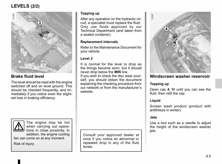
4.5
Windscreen washer reservoirTopping upOpen cap 4, fill until you can see the fluid, then refit the cap.
LiquidScreen wash product (product with antifreeze in winter).
JetsUse a tool such as a needle to adjust the height of the windscreen washer jets.
43
Brake fluid levelThe level should be read with the engine switched off and on level ground. This should be checked frequently, and im-mediately if you notice even the slight-est loss in braking efficiency.
Consult your approved dealer at once if you notice an abnormal or repeated drop in any of the fluid levels.
Topping upAfter any operation on the hydraulic cir-cuit, a specialist must replace the fluid.Only use fluids approved by our Technical Department (and taken from a sealed container).
Replacement intervalsRefer to the Maintenance Document for your vehicle.
Level 3It is normal for the level to drop as the linings become worn, but it should never drop below the MIN line.If you wish to check the disc wear your-self, you should obtain the document explaining the checking procedure from our network or from the manufacturer’s website.
LEVELS (2/2)
The engine may be hot when carrying out opera-tions in close proximity. In addition, the engine cooling
fan can come on at any moment.Risk of injury.

4.6
MaintenanceRefer to the Maintenance Document for your vehicle. The battery is a specific
type, please ensure it is replaced with the same type. Consult an approved
dealer.Handle the battery with care as it contains sulphuric acid, which must not come into contact with eyes or skin. If
it does, wash the affected area with plenty of cold water. If necessary, consult a doctor.Ensure that naked flames, red hot objects and sparks do not come into contact with the battery as there is a risk of explosion.
12 VOLT BATTERY (1/2)The charge status of the 12 volt bat-tery 1 can decrease, especially if you use your vehicle:– when the outside temperature drops;– after extended use of energy-con-
suming devices (radio etc.) with the engine switched off.
ReplacementAs this operation is complex, we advise you to contact an approved Dealer.
1
Do not work on the 12 volt battery (charging, replac-ing, etc.):– without switching off the
ignition;– if your traction battery is charging Please refer to the information on “Electric vehicle: charging” in Section 1.Risk of serious injury.
Replacing the 12 volt bat-tery:For your own safety, you must respect the replace-
ment intervals (without exceeding them) as stated in the maintenance document.

4.7
12 VOLT BATTERY (2/2)
Label AObserve the indications on the battery:– 2 naked flames and smoking are for-
bidden;– 3 eye protection required;– 4 keep away from children;– 5 explosive materials;– 6 refer to the handbook;– 7 corrosive materials.
The engine may be hot during operations in close proximity. In addition, the engine cooling fan may
start at any moment.Risk of injury.
A 2 3 4
567

4.8
B : dimension of the tyres fitted to the vehicle.C : tyre pressures for the front wheels.D : tyre pressures for the rear wheels.
TYRE PRESSURE
Label AOpen the driver’s door to read it.Tyre pressures should be checked when the tyres are cold.If the tyre pressures cannot be checked when the tyres are cold, increase the pressures from 0.2 to 0.3 bar (or 3 PSI). Never deflate a hot tyre.
C D
A
A
When they need to be re-placed, only tyres of the same make, size, type and profile should be used.
They must: either be identical to those fitted originally or conform to those recommended by your authorised dealer.
B
Tyre safety and use of snow chains: Refer to the information on “Tyres” in Section 5 for the servicing conditions and, depending on the version, the use of chains.
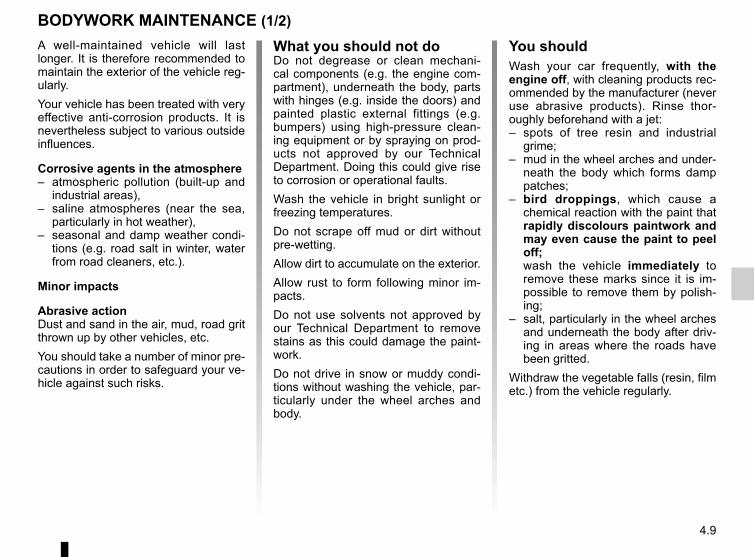
4.9
BODYWORK MAINTENANCE (1/2)
What you should not doDo not degrease or clean mechani-cal components (e.g. the engine com-partment), underneath the body, parts with hinges (e.g. inside the doors) and painted plastic external fittings (e.g. bumpers) using high-pressure clean-ing equipment or by spraying on prod-ucts not approved by our Technical Department. Doing this could give rise to corrosion or operational faults.Wash the vehicle in bright sunlight or freezing temperatures.Do not scrape off mud or dirt without pre-wetting.Allow dirt to accumulate on the exterior.Allow rust to form following minor im-pacts.Do not use solvents not approved by our Technical Department to remove stains as this could damage the paint-work.Do not drive in snow or muddy condi-tions without washing the vehicle, par-ticularly under the wheel arches and body.
A well-maintained vehicle will last longer. It is therefore recommended to maintain the exterior of the vehicle reg-ularly.Your vehicle has been treated with very effective anti-corrosion products. It is nevertheless subject to various outside influences.
Corrosive agents in the atmosphere– atmospheric pollution (built-up and
industrial areas),– saline atmospheres (near the sea,
particularly in hot weather),– seasonal and damp weather condi-
tions (e.g. road salt in winter, water from road cleaners, etc.).
Minor impacts
Abrasive actionDust and sand in the air, mud, road grit thrown up by other vehicles, etc.You should take a number of minor pre-cautions in order to safeguard your ve-hicle against such risks.
You shouldWash your car frequently, with the engine off, with cleaning products rec-ommended by the manufacturer (never use abrasive products). Rinse thor-oughly beforehand with a jet:– spots of tree resin and industrial
grime;– mud in the wheel arches and under-
neath the body which forms damp patches;
– bird droppings, which cause a chemical reaction with the paint that rapidly discolours paintwork and may even cause the paint to peel off;
wash the vehicle immediately to remove these marks since it is im-possible to remove them by polish-ing;
– salt, particularly in the wheel arches and underneath the body after driv-ing in areas where the roads have been gritted.
Withdraw the vegetable falls (resin, film etc.) from the vehicle regularly.

4.10
Using a roller type car washReturn the windscreen wiper stalk to the Park position (refer to the informa-tion on the “Windscreen washer, wiper” in Section 1). Check the mounting of external accessories, additional lights and mirrors, and ensure that the wiper blades are secured with adhesive tape.Remove the radio aerial mast if your vehicle is fitted with this equipment. Remember to remove the tape and refit the antenna after washing.
Observe the vehicle stopping distances when driving on gravelled surfaces to prevent paint damage.Repair, or have repaired quickly, areas where the paint has been damaged, to prevent corrosion spreading.Remember to visit the body shop pe-riodically in order to maintain your anti-corrosion warranty. Refer to the Maintenance Document.Respect local regulations about wash-ing vehicles (e.g. do not wash your ve-hicle on a public highway).If it is necessary to clean mechani-cal components, hinges, etc., spray them with products approved by our Technical Department to protect them after they have been cleaned.
BODYWORK MAINTENANCE (2/2)
Cleaning the headlightsAs the headlights are made of plastic “glass”, use a soft cloth or cotton wool to clean them. If this does not clean them properly, moisten the cloth with soapy water, then wipe clean with a soft damp cloth or cotton wool.Finally, carefully dry off with a soft dry cloth.Cleaning products containing alco-hol must not be used.
Vehicles with a matte paint finishThis type of paint requires certain pre-cautions.Do not do the following– use wax-based products (polishing);– rub too hard;– wash the vehicle in a roller-type car
wash;– wash the vehicle using a high-pres-
sure device;– attach stickers to the paintwork (risk
of leaving marks).You should do the followingWash the vehicle by hand using plenty of water, using a soft cloth or a gentle sponge.
We have selected special products to care for your vehicle and you can obtain these from the manufactur-er’s accessory outlets.
Washing the vehicleNever wash the engine compartment, the charging connection or the traction
battery with a high-pressure jet.This risks damaging the electric cir-cuit.Never wash the vehicle while it is charging.Risk of electric shock and a risk to life.

4.11
Glass instrument panel(e.g. instrument panel, clock, exterior temperature display, radio display, etc.)Use a soft cloth (or cotton wool).If this does not clean it properly, use a soft cloth (or cotton wool) slightly mois-tened with soapy water and then wipe clean with a soft damp cloth or cotton wool.Finally, carefully dry off with a soft dry cloth.Cleaning products containing alco-hol must not be used under any cir-cumstances.
Seat beltsThese must be kept clean.Use products selected by our Technical Department (Approved outlets) or warm, soapy water and a sponge and wipe with a dry cloth.Detergents or dyes must not be used under any circumstances.
INTERIOR TRIM MAINTENANCE (1/2)
Textiles (seats, door trim, etc)Vacuum-clean the textiles regularly.
Liquid stainUse soapy water.Dab lightly (never rub) with a soft cloth, rinse and remove the excess.
Solid or pasty stainCarefully remove the excess solid or pasty material immediately with a spatula (working from the edges to the centre to avoid spreading the stain).Clean as for a liquid stain.
Special instructions for sweets or chewing gumPut an ice cube on the stain to solidify it, then proceed as for a solid stain.
A well-maintained vehicle will last longer. It is therefore recommended to maintain the interior of the vehicle regu-larly.A stain should always be dealt with swiftly.Whatever type of stain is on the trim, use cold (or warm) soapy water with natural soap.Detergents (washing-up liquid, pow-dered products, alcohol-based prod-ucts) should not be used.Use a soft cloth.Rinse and soak up the excess.
For further recommendations for maintaining the interior, and/or for any unsatisfactory results, please see an authorised dealer.

4.12
You are strongly recom-mended not to use high-pressure or spray cleaning equipment inside the pas-
senger compartment: use of such equipment could impair the correct functioning of the electrical or elec-tronic components in the vehicle, or have other detrimental effects.
INTERIOR TRIM MAINTENANCE (2/2)
You should not:You are strongly advised not to po-sition objects such as deodorants, scents, etc. near air vents, as this could damage your dashboard trim.
Removal/replacing removable equipment originally fitted in the vehicleIf you need to remove equipment in order to clean the passenger com-partment (for example, mats), always ensure that they are correctly refitted and are the right way around (the driv-er’s mat should be fitted on the driver’s side, etc.) and fit them with the compo-nents supplied with the equipment (for example, the driver mat should always be fixed using the pre-fitted mounting components).With the vehicle stationary, ensure that nothing will impede driving (anything obstructing the pedals, heel wedged by the mat, etc.).

5.1
Section 5: Practical advice
Tool kit . . . . . . . . . . . . . . . . . . . . . . . . . . . . . . . . . . . . . . . . . . . . . . . . . . . . . . . . . . . . . . . . . . . . . . . . 5.2Wheel trim . . . . . . . . . . . . . . . . . . . . . . . . . . . . . . . . . . . . . . . . . . . . . . . . . . . . . . . . . . . . . . . . . . . . . 5.3Tyre inflation kit . . . . . . . . . . . . . . . . . . . . . . . . . . . . . . . . . . . . . . . . . . . . . . . . . . . . . . . . . . . . . . . . . 5.4Changing a wheel . . . . . . . . . . . . . . . . . . . . . . . . . . . . . . . . . . . . . . . . . . . . . . . . . . . . . . . . . . . . . . . 5.9Tyres (tyre and wheel safety, use in winter) . . . . . . . . . . . . . . . . . . . . . . . . . . . . . . . . . . . . . . . . . . . 5.11Headlights (changing bulbs) . . . . . . . . . . . . . . . . . . . . . . . . . . . . . . . . . . . . . . . . . . . . . . . . . . . . . . . 5.14Rear lights (changing bulbs) . . . . . . . . . . . . . . . . . . . . . . . . . . . . . . . . . . . . . . . . . . . . . . . . . . . . . . . 5.17Indicator lights (changing bulbs) . . . . . . . . . . . . . . . . . . . . . . . . . . . . . . . . . . . . . . . . . . . . . . . . . . . . 5.18Interior lights (changing bulbs) . . . . . . . . . . . . . . . . . . . . . . . . . . . . . . . . . . . . . . . . . . . . . . . . . . . . . 5.19Fuses . . . . . . . . . . . . . . . . . . . . . . . . . . . . . . . . . . . . . . . . . . . . . . . . . . . . . . . . . . . . . . . . . . . . . . . . . 5.2112 volt battery: breakdowns. . . . . . . . . . . . . . . . . . . . . . . . . . . . . . . . . . . . . . . . . . . . . . . . . . . . . . . . 5.23Radio frequency remote control unit: battery. . . . . . . . . . . . . . . . . . . . . . . . . . . . . . . . . . . . . . . . . . . 5.25Accessories . . . . . . . . . . . . . . . . . . . . . . . . . . . . . . . . . . . . . . . . . . . . . . . . . . . . . . . . . . . . . . . . . . . . 5.26Wipers (replacing blades) . . . . . . . . . . . . . . . . . . . . . . . . . . . . . . . . . . . . . . . . . . . . . . . . . . . . . . . . . 5.27Towing/breakdown . . . . . . . . . . . . . . . . . . . . . . . . . . . . . . . . . . . . . . . . . . . . . . . . . . . . . . . . . . . . . . . 5.28Operating faults . . . . . . . . . . . . . . . . . . . . . . . . . . . . . . . . . . . . . . . . . . . . . . . . . . . . . . . . . . . . . . . . . 5.31

5.2
TOOL KIT (1/2)
the tool kit contains tools and the tyre inflation kit. It is located in the boot.To get to it:– remove strap 1 and attach it 2.– position your hands at A and B;– pull the kit 3 towards you.To use the tyre inflation kit, please refer to “Tyre inflation kit” in Section 5. Do not leave the tools un-
secured inside the vehicle as they may come loose under braking. After use,
check that all the tools are correctly clipped into the tool kit, then position it correctly in its housing: there is a risk of injury.
1
2
B
A3
Inflation kitTo use the tyre inflation kit, please refer to “Tyre inflation kit” in Section 5.

5.3
TOOL KIT (2/2)/TRIM
ToolsThe composition of the tool kit varies according to the vehicle.
Rear lights key 4Used to unscrew the rear lights.
Front headlight key 5Used to unscrew the headlights.
Wheelbrace 6
Never leave tools unsecured in the vehicle: there is a risk that they may be thrown about during braking. After use, check that all the tools are correctly clipped into the tool kit, then position it correctly in its housing: there is a risk of injury.
Jack 7When replacing the jack, fold it cor-rectly and position the wheelbrace cor-rectly before replacing it in its position.
7
6
8
9
10
4
The jack is designed for wheel changing purposes only. Under no circum-stances should it be used
for carrying out repairs underneath the vehicle or to gain access to the underside of the vehicle.
Hubcap tool 8This tool is used to remove the wheel trims.
Wheel bolt guide 9To finish loosening or starting to tighten the wheel bolts.
Tow eye 10Refer to the information on “Towing” in Section 5.
Wheel trimRemove it using the hubcap tool 8 by connecting the hook in the recess pro-vided next to the valve 11 (to attach the metal clip).To refit the wheel trim, align it with valve 11. Push the retaining hooks in fully, starting with side C near the valve, followed by D and E, finishing at F op-posite the valve.NB: if you are using anti-theft bolts, refer to the information on “Changing a wheel”.
11
C
DE
F
5
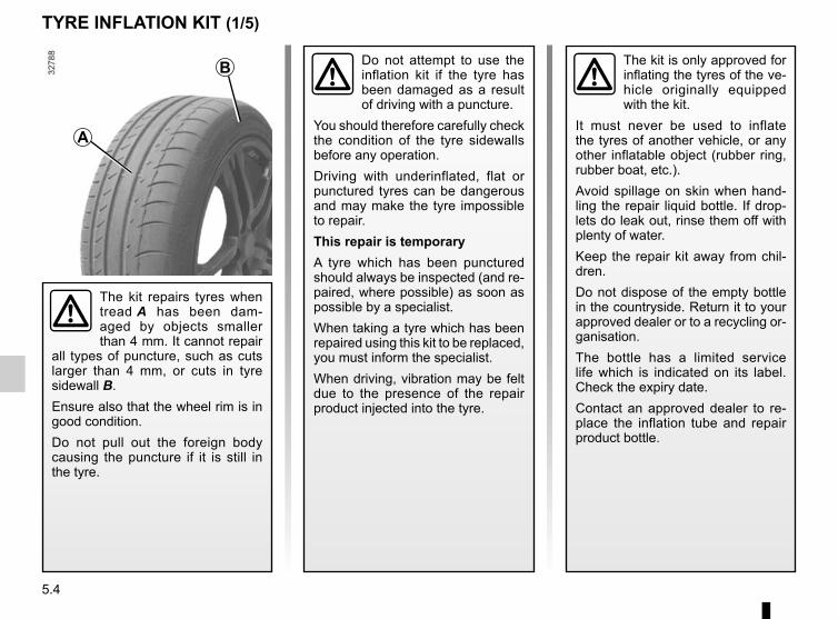
5.4
TYRE INFLATION KIT (1/5)
The kit is only approved for inflating the tyres of the ve-hicle originally equipped with the kit.
It must never be used to inflate the tyres of another vehicle, or any other inflatable object (rubber ring, rubber boat, etc.).Avoid spillage on skin when hand-ling the repair liquid bottle. If drop-lets do leak out, rinse them off with plenty of water.Keep the repair kit away from chil-dren.Do not dispose of the empty bottle in the countryside. Return it to your approved dealer or to a recycling or-ganisation.The bottle has a limited service life which is indicated on its label. Check the expiry date.Contact an approved dealer to re-place the inflation tube and repair product bottle.
A
B
The kit repairs tyres when tread A has been dam-aged by objects smaller than 4 mm. It cannot repair
all types of puncture, such as cuts larger than 4 mm, or cuts in tyre sidewall B.Ensure also that the wheel rim is in good condition.Do not pull out the foreign body causing the puncture if it is still in the tyre.
Do not attempt to use the inflation kit if the tyre has been damaged as a result of driving with a puncture.
You should therefore carefully check the condition of the tyre sidewalls before any operation.Driving with underinflated, flat or punctured tyres can be dangerous and may make the tyre impossible to repair.This repair is temporaryA tyre which has been punctured should always be inspected (and re-paired, where possible) as soon as possible by a specialist.When taking a tyre which has been repaired using this kit to be replaced, you must inform the specialist.When driving, vibration may be felt due to the presence of the repair product injected into the tyre.
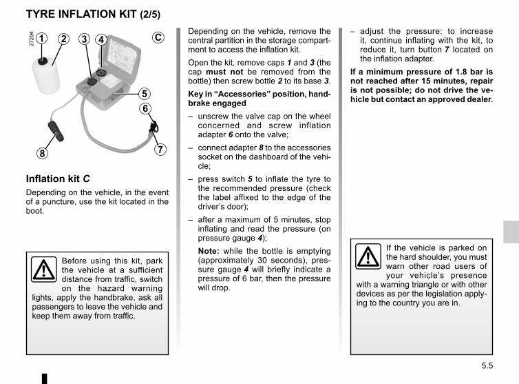
5.5
TYRE INFLATION KIT (2/5)
1 43
56
78
2Depending on the vehicle, remove the central partition in the storage compart-ment to access the inflation kit.Open the kit, remove caps 1 and 3 (the cap must not be removed from the bottle) then screw bottle 2 to its base 3.Key in “Accessories” position, hand-brake engaged– unscrew the valve cap on the wheel
concerned and screw inflation adapter 6 onto the valve;
– connect adapter 8 to the accessories socket on the dashboard of the vehi-cle;
– press switch 5 to inflate the tyre to the recommended pressure (check the label affixed to the edge of the driver’s door);
– after a maximum of 5 minutes, stop inflating and read the pressure (on pressure gauge 4);Note: while the bottle is emptying (approximately 30 seconds), pres-sure gauge 4 will briefly indicate a pressure of 6 bar, then the pressure will drop.
– adjust the pressure: to increase it, continue inflating with the kit, to reduce it, turn button 7 located on the inflation adapter.
If a minimum pressure of 1.8 bar is not reached after 15 minutes, repair is not possible; do not drive the ve-hicle but contact an approved dealer.
Inflation kit CDepending on the vehicle, in the event of a puncture, use the kit located in the boot.
Before using this kit, park the vehicle at a sufficient distance from traffic, switch on the hazard warning
lights, apply the handbrake, ask all passengers to leave the vehicle and keep them away from traffic.
If the vehicle is parked on the hard shoulder, you must warn other road users of your vehicle’s presence
with a warning triangle or with other devices as per the legislation apply-ing to the country you are in.
C

5.6
TYRE INFLATION KIT (3/5)
9
8
– affix driving recommendation label 9 to the dashboard where it can easily be seen by the driver;
– store the kit;– after the first inflation procedure the
tyre will still be leaking; it is vital to drive in order to plug the hole;
– start immediately and drive at be-tween 12 and 40 mph (20 and 60 km/h) in order to distribute the product evenly in the tyre and, after driving for 2 miles, stop and check the pressure;
– If the pressure is greater than 1.3 bar but less than the recommended pressure, readjust it (please refer to the label affixed to the edge of the driver’s door). Otherwise, please contact an authorised dealer: the tyre cannot be repaired.
Note: after using the inflation kit, you should visit an approved Dealer to re-place the inflation hose and the bottle of repair product.
Precautions when using the kitThe kit should not be operated for more than 15 consecutive minutes.
Nothing should be placed around the driver’s feet as such objects may slide under the pedals during
sudden braking manoeuvres and obstruct their use.
Once the tyre is inflated correctly:– stop using the kit;– close the integrated cap on the bottle
again;– disconnect adapter 8;
Following repair with the kit, do not travel further than 120 miles (200 km). In addi-tion, reduce your speed and
under no circumstances exceed 48 mph (80 km/h). The sticker, which you must affix in a prominent position on the dashboard, reminds you of this.Depending on the country or local legislation, a tyre repaired with the inflation kit may need to be replaced.
Please be aware that a poorly tightened or miss-ing valve cap can make the tyres less airtight and lead
to pressure loss.Always use valve caps identical to those fitted originally and tighten them fully.

5.7
TYRE INFLATION KIT (4/5)
Inflation kit DDepending on the vehicle, in the event of a puncture, use the kit located in the boot.
Before using this kit, park the vehicle at a sufficient distance from traffic, switch on the hazard warning
lights, apply the handbrake, ask all passengers to leave the vehicle and keep them away from traffic.
1314
1017
11
12
16
15
DWith the engine running and the parking brake applied,– unroll the hose from the container;– connect the compressor hose 12 to
the container’s inlet 17;– depending on the vehicle, connect
the container 17 to the compressor from the container recess 16;
– unscrew the valve cap on the rel-evant wheel and screw on the con-tainer’s inflation adapter 10;
– adapter 11 must be connected to the vehicle accessories socket;
– press switch 13 to inflate the tyre to the recommended pressure (please refer to the information in the section on “Tyre pressure”);
– after a maximum of 15 minutes, stop inflating and read the pressure (on pressure gauge 14).Note: while the container is empty-ing (approximately 30 seconds), the pressure gauge 14 will briefly indi-cate a pressure of up to 6 bar. The pressure will then drop.
– adjust the pressure: to increase it, continue inflation with the kit; to reduce it, press button 15.
If a minimum pressure of 1.8 bar is not reached after 15 minutes, repair is not possible; do not drive the ve-hicle but contact an approved dealer.
If the vehicle is parked on the hard shoulder, you must warn other road users of your vehicle’s presence
with a warning triangle or with other devices as per the legislation apply-ing to the country you are in.

5.8
TYRE INFLATION KIT (5/5)
Once the tyre is correctly inflated, remove the kit: slowly unscrew the in-flation adapter 10 to prevent any repair product from escaping and store the container in plastic packaging to pre-vent the product from escaping.
– Affix the driving recommendation label to the dashboard where it can easily be seen by the driver;
– Put the kit away.– At the end of this initial inflation op-
eration, air will still escape from the tyre. You must drive a short distance in order to seal the hole.
– Start immediately and drive at be-tween 12 and 40 mph (20 and 60 km/h) in order to distribute the product evenly in the tyre and, after driving for 2 miles (3 km), stop and check the pressure.
– If the pressure is greater than 1.3 bar but less than the recommended pressure (refer to the label affixed to the edge of the driver’s door), read-just it. Otherwise, please contact an authorised dealer: the tyre cannot be repaired.
Precautions when using the kitThe kit should not be operated for more than 15 consecutive minutes.
Nothing should be placed around the driver’s feet as such objects may slide under the pedals during
sudden braking manoeuvres and obstruct their use.
10
Please be aware that a poorly tightened or miss-ing valve cap can make the tyres less airtight and may
lead to pressure loss.Always use valve caps identical to those fitted originally and tighten them fully.
Following repair with the kit, do not travel further than 120 miles (200 km). In addi-tion, reduce your speed and
under no circumstances exceed 48 mph (80 km/h). The sticker, which you must affix in a prominent position on the dashboard, reminds you of this.Depending on the country or local legislation, a tyre repaired with the inflation kit may need to be replaced.

5.9
Vehicles equipped with a jack and wheelbraceIf necessary, remove the wheel trim.– Use the wheelbrace 3 to slacken off
the wheel bolts. Position it so as to be able to push from above;
– place the jack 4 horizontally; the jack head must be lined up with the sill 1 closest to the wheel concerned, as shown by arrow 2.
– start cranking the jack up by hand to align the base plate (which should be pushed slightly under the vehicle);
– turn the wheelbrace until the wheel lifts off the ground;
– undo the bolts and take off the wheel;– fit the emergency spare wheel on the
central hub and turn it to locate the mounting holes in the wheel and the hub.
CHANGING A WHEEL (1/2)
Switch on the hazard warn-ing lights.Keep the vehicle away from traffic and on a level sur-
face where it will not slip (if neces-sary, place a solid support under the jack base).Engage the handbrake and put the gearstick in position P.Ask all the passengers to leave the vehicle and keep them away from traffic.
3
4
1 2
To prevent any risk of injury or damage to the vehi-cle, raise the jack until the wheel you are replacing is
a maximum of 3 centimetres off the ground.
If the vehicle is not equipped with a jack or wheelbrace, you can obtain these from your authorised dealer.If the vehicle is parked on
the hard shoulder, you must warn other road users of your vehicle’s presence
with a warning triangle or with other devices as per the legislation apply-ing to the country you are in.

5.10
CHANGING A WHEEL (2/2)
If you have a puncture, re-place the wheel as soon as possible.A tyre which has been punc-
tured should always be inspected (and repaired, where possible) by a specialist.
Anti-theft boltIf you use anti-theft bolts, fit these nearest the valve (wheel embel-lisher may not be able to fit).
With the wheel on the ground, tighten the bolts fully and have the tightness of the bolts checked (tightening torque: 110 N.m) and the emergency spare wheel pressure checked as soon as possible.

5.11
TYRES (1/3)
Maintaining the tyresThe tyres must be in good condition and the tread form must have sufficient depth; tyres approved by our Technical Department have wear warning strips 1 that are indicators moulded into the tread at several points.
Tyre and wheel safetyThe tyres are the only contact between the vehicle and the road, so it is essen-tial to keep them in good condition.You must make sure that your tyres conform to local road traffic regulations.
When the tyre tread has been worn to the level of the wear indicators, they become visible 2: it is then necessary to replace your tyres because the tread rubber is no more than 1.6 mm deep, resulting in poor roadholding on wet roads.An overloaded vehicle, long journeys by motorway, particularly in very hot weather, or continual driving on poorly surfaced minor roads will lead to more rapid tyre wear and affect safety.
When they need to be re-placed, only tyres of the same make, size, type and profile should be used.
Tyres fitted to the vehicle should either be identical to those fitted originally or conform to those recommended by your approved dealer.
Incidents which occur when driving, such as striking the kerb, may damage the tyres and wheel rims, and could
also lead to misalignment of the front or rear axle geometry. In this case, have the condition of these checked by an approved dealer.
2
1

5.12
TYRES (2/3)
Tyre pressuresAdhere to the tyre pressures. The tyre pressures should be checked at least once a month and additionally before any long journey (refer to the label af-fixed to the edge of the driver’s door).Please refer to the information on “Tyre pressures” in Section 4.
Pressures should be checked when the tyres are cold; ignore higher pressures which may be reached in hot weather or following a fast journey.If tyre pressures cannot be checked when the tyres are cold, the normal pressures must be increased by 0.2 to 0.3 bar (or 3 PSI).Never deflate a hot tyre.
Special noteDepending on the vehicle, there may be an adapter which needs to be posi-tioned on the valve before air is added.
Fitting new tyres
Incorrect tyre pressures lead to abnormal tyre wear and unusually hot running. These are factors which
may seriously affect safety and lead to:– poor road holding,– risk of bursting or tread separa-
tion.The pressure depends on the load and the speed of use. Adjust the pressure according to the condi-tions of use (refer to the label affixed to the edge of the driver’s door).
Please be aware that a poorly tightened or miss-ing valve cap can make the tyres less airtight and lead
to pressure loss.Always use valve caps identical to those fitted originally and tighten them fully.
For safety reasons, this op-eration must be carried out by a specialist.Fitting different tyres may
change your vehicle as follows:– It may mean that your vehicle no
longer conforms to current regu-lations;
– It may change the way it handles when cornering;
– It may cause the steering to be heavy;
– It may affect the use of snow chains.

5.13
TYRES (3/3)
Use in winterChainsFor safety reasons, fitting snow chains to the rear axle is strictly for-bidden.Chains cannot be fitted to tyres which are larger than those originally fitted to the vehicle.Snow or Winter tyresWe would recommend that these be fitted to all four wheels to ensure that your vehicle retains maximum adhe-sion.Warning: These tyres sometimes have a specific direction of rotation and a maximum speed index which may be lower than the maximum speed of your vehicle.
Chains may only be fitted to tyres of the same size as those originally fitted to your vehicle.
Chains may be fitted, provided that they are specific chains. We would advise you to consult an approved Dealer. In all cases, we would recommend
that you contact an approved dealer who will be able to advise you on the choice of equipment which is most suitable for your vehicle.
Studded tyresThis type of equipment may only be used for a limited period and as laid down by local legislation. It is neces-sary to observe the speed specified by current legislation.These tyres must, at a minimum, be fitted to the two front wheels.
NB:The use of snow tyres, winter tyres or studded tyres significantly reduces the vehicle range.

5.14
FRONT HEADLIGHTS: changing bulbs (1/2)
Direction indicatorsRemove cover B, unscrew bulb holder 2 a quarter of a turn and un-screw the bulb a quarter of a turn.Bulb type: PY21W.
The bulbs detailed below can be re-placed. However, we recommend that these be replaced by an approved dealer if this proves difficult. After open-ing the bonnet, unscrew the screws 1 using standard tools or, depending on the vehicle, using the spanners pro-vided in the tool kit.Pull the headlight as far as possible in the direction shown by the arrow.Note: the headlight cannot be pulled out completely. Avoid pulling too hard, as this could damage the connections.
B C D 2 431
Obtain an emergency kit containing a set of spare bulbs and fuses from an approved Dealer.
Do not do any work under the bonnet when the vehicle is charging or when the igni-tion is switched on.

5.15
FRONT HEADLIGHTS: replacing bulbs (2/2)
Dipped beam headlights CRemove cover C, then unclip bulb con-nector 3.Press the top of clip 6, remove the as-sembly from its housing and take out the bulb.Bulb type: H7.It is essential to use anti U.V. 55W bulbs so as not to damage the plastic on the headlights.Do not touch the bulb glass.When the bulb has been changed, make sure you refit the cover correctly.
B C D 2 543
6
The bulbs are under pres-sure and can break when replaced.Risk of injury.
The engine may be hot when carrying out opera-tions in close proximity. In addition, the engine cooling
fan can come on at any moment.Risk of injury.
Main beam headlightsUnscrew cover D a quarter of a turn and remove connector 4 with the bulb.Remove the lamp from the connector.Bulb type: H7.
Side lightsUnscrew cover D a quarter of a turn, pull bulb holder 5 and take out the bulb.Bulb type: W5W.

5.16
FRONT HEADLIGHTS: front fog lights, additional lightsAdditional lightsIf you wish to fit fog lights or long range headlights to your vehicle, consult an authorised dealer.
Any operation on (or modi-fication to) the electrical system must be performed by an approved dealer
since an incorrect connection might damage the electrical equipment (harness, components and in partic-ular the alternator). In addition, your Dealer has all the parts required for fitting these units.
Front fog lights 1However, because the front bumper needs to be removed, you are advised to have your bulbs replaced by an approved dealer.
The bulbs are under pres-sure and can break when replaced.Risk of injury.
1

5.17
Direction indicator lights 4Bulb type: PY21W.
Side light and brake light 5Bulb type: P21/5W.
Direction indicator lights/brake and side lights– Open the boot and unscrew bolts 1
using the rear lights key (refer to the information on the “Tool kit” in Section 5), then take out the light unit by pulling it back.
– Release clips 3 to remove bulb holder 2.
– Unscrew bulb holder 4 or 5 and re-place the bulb.
Note: ensure that the cable is in place before inserting the light unit.
REAR LIGHTS AND SIDE LIGHTS: changing bulbs (1/2)
4
5
RefittingTo refit, proceed in the reverse order, taking care not to damage the wiring.
13
2
The bulbs are under pres-sure and can break when replaced.Risk of injury.

5.18
REAR LIGHTS AND SIDE LIGHTS: changing bulbs (2/2)
Reversing light or rear fog light 7 or 8Please see an authorised dealer.
High-level brake light 6Consult an approved Dealer.
Side indicator lights 11– Unclip indicator light 11 (using a flat-
blade screwdriver type tool posi-tioned at A to move the indicator light towards the front of the vehicle);
– Turn the bulb holder a quarter of a turn and take out the bulb.
Bulb type: W5W.
Number plate lights 10– Unclip light 10 by pressing tab 9;– remove the light cover to gain access
to the bulb.Bulb type: W5W.
11
A
The bulbs are under pres-sure and can break when replaced.Risk of injury.
6
8
7
910

5.19
INTERIOR LIGHTING: changing bulbs (1/2)
The bulbs are under pres-sure and can break when replaced.Risk of injury.
Courtesy light– Position the 3 switches in the central
position;– move the courtesy light backwards
(movement A) then tilt the front downwards (movement B);
– when removing the courtesy light, ensure that you do not pull the elec-trical wires;
– unclip the lens 1;Note: to remove the defective bulb, you can use a flat-blade screwdriver or sim-ilar.Bulb type: W5W.
Glove box lightOpen the access cover 3, you can then unclip the bulb holder more easily 4.Bulb type: C5W.
Door lightsUnclip light 2 (using a flat-blade screw-driver or similar).Turn the bulb holder a quarter of a turn and take out the bulb.Bulb type: W5W.
2
4
B
A
3
1

5.20
INTERIOR LIGHTING: replacing bulbs (2/2)
The bulbs are under pres-sure and can break when replaced.Risk of injury.
Luggage compartment lightUnclip the light 5 (using a tool such as a flat-blade screwdriver).
Disconnect the light.Press tab 6 to release the lens 8 and access bulb 7.Bulb type: W5W.
6 7 8
5

5.21
Fuse boxIf any electrical component does not work, check the condition of the fuses.Unclip flap A for left-hand drive vehicles or B for right-hand drive vehicles.
Tweezers 1Remove the fuse using tweezers 1, lo-cated at the back of cover A or B.To remove the fuse from the tweezers, slide the fuse to the side.It is not advisable to use the free fuse locations.
Check the fuse in question and replace it, if neces-sary, by a fuse of the same rating.
If a fuse is fitted where the rating is too high, it may cause the electrical circuit to overheat (risk of fire) in the event of an item of equipment using an excessive amount of current.
FUSES (1/2)
1
A
B
In accordance with local legislation or as a precautionary measure:Obtain an emergency kit containing a set of spare bulbs and fuses from an approved Dealer.
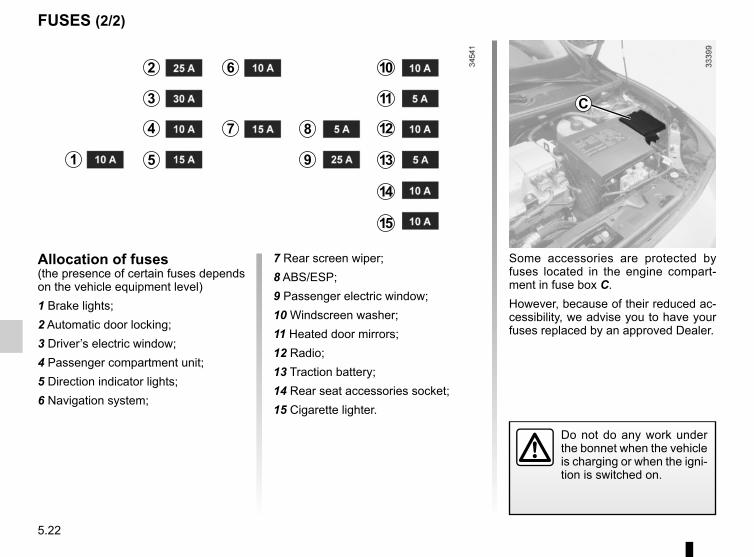
5.22
FUSES (2/2)
Some accessories are protected by fuses located in the engine compart-ment in fuse box C.However, because of their reduced ac-cessibility, we advise you to have your fuses replaced by an approved Dealer.
Allocation of fuses(the presence of certain fuses depends on the vehicle equipment level)1 Brake lights;2 Automatic door locking;3 Driver’s electric window;4 Passenger compartment unit;5 Direction indicator lights;6 Navigation system;
7 Rear screen wiper;8 ABS/ESP;9 Passenger electric window;10 Windscreen washer;11 Heated door mirrors;12 Radio;13 Traction battery;14 Rear seat accessories socket;15 Cigarette lighter.
C
1
2
3
4
5
6
7 8
9
10
11
12
13
14
15
Do not do any work under the bonnet when the vehicle is charging or when the igni-tion is switched on.

5.23
To avoid all risk of sparks:– Switch off the vehicle ignition.– Ensure that any electrical consumers
(courtesy lights, etc.) are switched off before disconnecting or recon-necting the battery.
– When charging, stop the charger before connecting or disconnecting the battery.
– Do not place metal objects on the battery to avoid creating a short cir-cuit between the terminals.
– Make sure that you reconnect the battery terminals after refitting.
12 VOLT BATTERY: breakdown recovery (1/2)
Connecting a battery chargerThe battery charger must be com-patible with a battery with nominal voltage of 12 volts.Before disconnecting the battery, check that:– the ignition is switched off;– the gear control should be in posi-
tion P (please refer to the information on the “Gear control” in Section 2;
– the charging cable is disconnected.
Special procedures may be required to charge some batteries. Contact your ap-proved dealer.
Avoid all risk of sparks which may cause an immediate explosion, and charge the battery in a well-venti-lated area. Risk of serious injury.
Handle the battery with care as it contains sulphuric acid, which must not come into contact with eyes or skin. If
it does, wash the affected area with plenty of cold water. If necessary, consult a doctor.Ensure that naked flames, red hot objects and sparks do not come into contact with the battery as there is a risk of explosion.The engine may be hot when car-rying out operations in close prox-imity. In addition, the engine cooling fan can come on at any moment.Risk of injury.
Disconnect the leads connected to both battery terminals, starting with the negative terminal.Follow the instructions given by the manufacturer of the battery charger you are using.
Do not work on the 12 volt battery (charging, replac-ing, etc.):– without switching off the
ignition;– if your traction battery is charg-
ing. Please refer to the information on “Electric vehicle: charging” in Section 1.Risk of serious injury.

5.24
Attach positive lead A to mounting 1 attached to (+) terminal 2 then to (+) terminal 3 of the battery supplying the current.Attach the negative lead B to the (– ) terminal 4 of the battery supplying the current, then to the (–) terminal 5 of the discharged battery.
Starting the vehicle using the battery from another vehicleIf you have to use the battery from an-other vehicle to start, obtain suitable jump leads (with a large cross section) from an approved dealer or, if you al-ready have jump leads, ensure that they are in perfect condition.The two batteries must have an iden-tical nominal voltage of 12 volts. The battery supplying the current should have a capacity (amp-hours, Ah) which is at least the same as that of the dis-charged battery.Switch off your vehicle ignition. Ensure that there is no risk of contact between the two vehicles (risk of short circuiting when the positive terminals are con-nected) and that the discharged battery is properly connected.Start the engine of the vehicle supply-ing the current and run it at an interme-diate engine speed.
12 VOLT BATTERY: breakdown recovery (2/2)
2
34
5
A
B1
Check that there is no con-tact between leads A and B and that the positive lead A is not touching any metal
parts on the vehicle supplying the current.Risk of injury and/or damage to the vehicle.
251
Do not use your electric vehicle to restart the 12 volt battery in a conventional vehicle. The 12 volt electric power of an electric vehicle is not enough to perform such an operation. Risk of damage to vehicle
As soon as it starts, disconnect cables A and B in reverse order (5 - 4 - 3 - 2).

5.25
RADIO FREQUENCY REMOTE CONTROL: battery
Replacing the batteryOpen the case at slot 1 using a coin, and replace battery 2, observing the polarity shown on the back of the cover.
Note: It is not advisable to touch the electrical circuit in the key cover when replacing the battery.Do not touch the battery or the contact strips with your fingers. Use a soft cloth.
Do not dispose of your used batteries in the countryside. Give them to an organisa-tion that collects and recy-
cles used batteries.
Batteries can be obtained from your approved Dealer.These batteries should have a serv-ice life of approximately two years.
When refitting, ensure that the cover is correctly clipped into place.
12

5.26
ACCESSORIES
Electrical and electronic accessoriesBefore installing this type of accessory, make sure it is compatible with your vehicle. You can get advice from an au-thorised dealer.To install an accessory requiring intervention with the vehicle’s 12 V electrical circuit, please follow these instructions:
– disconnect the charging cord from the traction battery;– switch off the ignition;– disconnect the 12 V battery.Risk of serious injury.Connect accessories with a maximum power of 120 watts only. Fire hazard.No work may be carried out on the vehicle’s electrical or radio circuits, except by authorised dealers: an incorrectly connected system may result in damage being caused to the electrical equipment and/or the components connected to it.If the vehicle is fitted with any aftermarket electrical equipment, make sure that the installation is correctly protected by a fuse. Establish the rating and position of this fuse.
Use of transmission/receiving devices (telephones, CB equipment etc.).Telephones and CB equipment with integrated aerials may cause interference to the electronic systems originally fitted to the vehicle: it is advisable only to use equipment with an external aerial. Furthermore, we remind you of the need to conform to the legislation in force concerning the use of such equipment.
Fitting after-market accessoriesIf you wish to install accessories on the vehicle: please contact an authorised dealer. Also, to ensure the correct operation of your vehicle, and to avoid any risk to your safety, we recommend that you use only accessories specifically designed for your vehicle, which are the only accessories for which the manufacturer will provide a warranty.If you are using an anti-theft device, only attach it to the brake pedal.Obstructions to the driverOn the driver’s side, only use mats suitable for the vehicle, attached with the pre-fitted components, and check the fitting regu-larly. Do not lay one mat on top of another. There is a risk of wedging the pedals

5.27
WINDSCREEN WIPER BLADES
Replacing wiper blades 1With the ignition on and the engine switched off, lower the windscreen wiper stalk completely: they stop slightly away from the bonnet.Lift wiper arm 3, pull tab 2 (move-ment A) and push the blade upwards.
To refitSlide the blade along the arm until it clips on. Make sure that the blade is correctly locked in position. Return the windscreen wiper stalk to the park po-sition.
1
2
3
Keep monitoring the condition of the wiper blades. How long they last de-pends on you:– clean the blades and the wind-
screen regularly with soapy water;
– do not use them when the wind-screen is dry;
– free them from the windscreen when they have not been used for a long time.
A
– In frosty weather, make sure that the wiper blades are not stuck by ice (to avoid the risk of the motor
overheating).– Check the condition of the wiper
blades.They should be replaced as soon as they become less efficient: ap-proximately once a year.
When changing the blade, when it has been removed, do not let the wiper arm fall against the window: risk of breaking the window.

5.28
TOWING, BREAKDOWN (1/3)
Choice of breakdown serviceIn the event of an energy faultIn the event of a fully discharged trac-tion battery, any type of towing is per-mitted: towing on a flatbed truck or towing on the road using the tow eye (please see following pages).
All other casesOnly towing on a flatbed truck is per-mitted.
Before repairs, insert the key in the igni-tion to unlock the steering column. Turn it to position M.The regulations in force for breakdown recovery must always be observed.
Towing on a flatbed truckBreakdown recovery must be per-formed on a flat surface under all cir-cumstances except where the vehicle is immobilised following a full discharge of the traction battery. In the event of a total energy loss, please see the follow-ing pages.
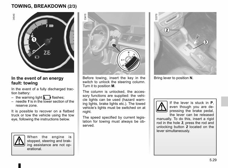
5.29
Bring lever to position N.In the event of an energy fault: towingIn the event of a fully discharged trac-tion battery:– the warning light � flashes;– needle 1 is in the lower section of the
reserve zone.It is possible to recover on a flatbed truck or tow the vehicle using the tow eye, following the instructions below.
Before towing, insert the key in the switch to unlock the steering column. Turn it to position M.The column is unlocked, the acces-sory functions are supplied: the vehi-cle lights can be used (hazard warn-ing lights, brake lights etc.). The towed vehicle’s lights must be switched on at night.The speed specified by current legis-lation for towing must always be ob-served.
TOWING, BREAKDOWN (2/3)
When the engine is stopped, steering and brak-ing assistance are not op-erational.
If the lever is stuck in P, even though you are de-pressing the brake pedal, the lever can be released
manually. To do this, insert a rigid rod in the hole 3, press the rod and unlocking button 2 located on the lever simultaneously.
2
31

5.30
TOWING, BREAKDOWN (3/3)
Access to towing pointsOnly use the front 6 and rear 7 towing points.These towing points may only be used for towing: never use them for lifting the vehicle directly or indirectly.
Unclip cover 5 or 8 by inserting a flat-blade screwdriver or similar under the cover.Tighten towing hitch 4 fully: as much as possible by hand at first, then finish tightening it using the wheelbrace.Only use the tow hitch 4 and the wheel-brace located under the boot carpet in the tool kit (please refer to the para-graph entitled “Tool kit”).
Do not leave the tools unse-cured inside the vehicle as they may come loose under braking.
After use, check that all the tools are correctly clipped into the tool kit, then, depending on the vehicle, po-sition it correctly in its housing.Risk of injury.
67
4
45
8
Do not remove the key from the ignition when the vehi-cle is being towed.

5.31
OPERATING FAULTS (1/4)The following advice will enable you to carry out quick, temporary repairs. For safety reasons you should always contact an approved dealer as soon as possible.
FAULTS POSSIBLE CAUSES WHAT TO DO
Impossible to charge the traction bat-tery.
No electrical current in domes-tic sockets or poor connection of cable to domestic socket.
Check your installation (circuit breaker, pro-grammer, etc.).Check the connections (socket, etc.). Please refer to the information on “Electric vehicle: charging” in Section 1.
The outdoor temperature is lower than -26°C.
Recharge your vehicle in a more suitable environment. If necessary, refer to the para-graph on “Towing, breakdown” in Section 5.
The cord is defective. Please see an authorised dealer to replace it.
The programmable air conditioning fails to work.
One of the usage conditions is not complied with (the traction battery is not charged, etc).
Please refer to the information on “Air-conditioning: programming” in Section 3.

5.32
OPERATING FAULTS (2/4)
FAULTS POSSIBLE CAUSES WHAT TO DO
The remote control does not lock or unlock the doors.
The remote control battery is flat. Use the emergency key.
Use of appliances operating on the same frequency as the remote control (mobile phone, etc.).
Stop using the devices or use the key.
Vehicle located in a high electro-magnetic radiation zone.Discharged battery.
Replace the battery. You can still lock/unlock and start your vehicle (refer to the in-formation on “Locking, unlocking the open-ing elements” in Section 1 and “Starting, stopping the engine” in Section 2).
The steering column remains locked. Steering wheel locked. To unlock, move the key and the steering wheel (please refer to the information on “Starting, stopping the engine” in Section 2).
Vibrations. Tyres not inflated to correct pres-sures, incorrectly balanced or dam-aged.
Check the tyre pressures. If this is not the problem, have them checked by an ap-proved Dealer.

5.33
Electrical equipment POSSIBLE CAUSES ACTION REQUIREDThe wipers do not work. Wiper blades stuck. Free the blades before using the wipers.
Broken windscreen wiper fuse. Consult an approved dealer.
Motor fault. Consult an approved dealer.
The wiper does not stop. Faulty electrical controls. Consult an approved dealer.
Direction indicators flashing more quickly. Blown bulb. Replace the bulb.
The indicators are not working.
On one side only: – blown bulb, Replace the bulb.Consult an approved dealer.
On both sides: – fuse blown, Replace it.
– faulty flasher unit. Needs replacing: please see an author-ised dealer.
OPERATING FAULTS (3/4)
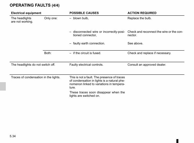
5.34
OPERATING FAULTS (4/4)
Electrical equipment POSSIBLE CAUSES ACTION REQUIREDThe headlightsare not working.
Only one: – blown bulb, Replace the bulb.
– disconnected wire or incorrectly-posi-tioned connector,
Check and reconnect the wire or the con-nector.
– faulty earth connection. See above.
Both: – if the circuit is fused. Check and replace if necessary.
The headlights do not switch off. Faulty electrical controls. Consult an approved dealer.
Traces of condensation in the lights. This is not a fault. The presence of traces of condensation in lights is a natural phe-nomenon linked to variations in tempera-ture.These traces soon disappear when the lights are switched on.

6.1
Section 6: Technical specifications
Vehicle identification plates . . . . . . . . . . . . . . . . . . . . . . . . . . . . . . . . . . . . . . . . . . . . . . . . . . . . . . . . 6.2Engine identification plate . . . . . . . . . . . . . . . . . . . . . . . . . . . . . . . . . . . . . . . . . . . . . . . . . . . . . . . . . 6.3Engine specification. . . . . . . . . . . . . . . . . . . . . . . . . . . . . . . . . . . . . . . . . . . . . . . . . . . . . . . . . . . . . . 6.3Weights . . . . . . . . . . . . . . . . . . . . . . . . . . . . . . . . . . . . . . . . . . . . . . . . . . . . . . . . . . . . . . . . . . . . . . . 6.4Dimensions . . . . . . . . . . . . . . . . . . . . . . . . . . . . . . . . . . . . . . . . . . . . . . . . . . . . . . . . . . . . . . . . . . . . 6.5Replacement parts and repairs . . . . . . . . . . . . . . . . . . . . . . . . . . . . . . . . . . . . . . . . . . . . . . . . . . . . . 6.6Service sheets . . . . . . . . . . . . . . . . . . . . . . . . . . . . . . . . . . . . . . . . . . . . . . . . . . . . . . . . . . . . . . . . . . 6.7Anti-corrosion check . . . . . . . . . . . . . . . . . . . . . . . . . . . . . . . . . . . . . . . . . . . . . . . . . . . . . . . . . . . . . 6.13

6.2
VEHICLE IDENTIFICATION PLATES
A
B
A
The information shown on the ve-hicle identification plate should be quoted on all correspondence or orders.
Vehicle identification plate A 1 Manufacturer name. 2 EC design number or approval
number. 3 Identification number.
Depending on the vehicle, this information is also given on marking B.
4 MAM (Maximum Authorised Mass) for front axle.
5 GTW (Gross train weight: vehicle fully loaded, with trailer).
6 MPAW (Maximim Permissible Weight) for front axle.
7 MPAW on rear axle.
8 Reserved for related or additional entries.
9 Paint reference (colour code).
78
9 65432
1

6.3
ENGINE IDENTIFICATION PLATE/ENGINE SPECIFICATION
Engine identification plateThe information on the engine plate (or label) C should be quoted on all your correspondence or orders.(Location varies depending on engine) 1 Engine type. 2 Engine suffix. 3 Engine number.
C2
3
1
C
Engine specificationEngine type 1: 5AM

6.4
WEIGHTS (in kg)The weights indicated for a basic vehicle without options: they vary depending on the your vehicle’s equipment. Consult your approved Dealer.
Maximum permissible all-up weight (MMAC)Total train weight (MTR)
Weights are indicated on the vehicle identification plate (refer to the information on “Vehicle identification plates” in Section 6)
Braked Trailer Weight Prohibited
Unbraked Trailer Weight Prohibited
Permissible nose weight Prohibited
Permissible load on the roof with the carrying device 80 kg (including the carrying device)

6.5
DIMENSIONS (in metres)
0,907 2,701 1,140 1,545
4,748
1,462*
1.563
2,037* Unladen

6.6
Original parts are based on strict specifications and are subject to highly-specialised tests. Therefore, they are of at least the same level of quality as the parts fitted originally.If you always fit genuine replacement parts to your vehicle, you will ensure that it performs well. Furthermore, repairs carried out within the manufacturer’s Network using original parts are guaranteed according to the conditions set out on the reverse of the repair order.
REPLACEMENT PARTS AND REPAIRS

6.7
Date: Miles (Km): Invoice number: Comments/miscellaneousType of operation: StampService □....................................... □Anti-corrosion check:OK □ Not OK* □*See specific page
Date: Miles (Km): Invoice number: Comments/miscellaneousType of operation: StampService □....................................... □Anti-corrosion check:OK □ Not OK* □*See specific page
Date: Miles (Km): Invoice number: Comments/miscellaneousType of operation: StampService □....................................... □Anti-corrosion check:OK □ Not OK* □
*See specific page
VIN: ..................................................................................
SERVICE SHEETS (1/6)

6.8
SERVICE SHEETS (2/6)
VIN: ..................................................................................
Date: Miles (Km): Invoice number: Comments/miscellaneousType of operation: StampService □....................................... □Anti-corrosion check:OK □ Not OK* □*See specific page
Date: Miles (Km): Invoice number: Comments/miscellaneousType of operation: StampService □....................................... □Anti-corrosion check:OK □ Not OK* □*See specific page
Date: Miles (Km): Invoice number: Comments/miscellaneousType of operation: StampService □....................................... □Anti-corrosion check:OK □ Not OK* □
*See specific page
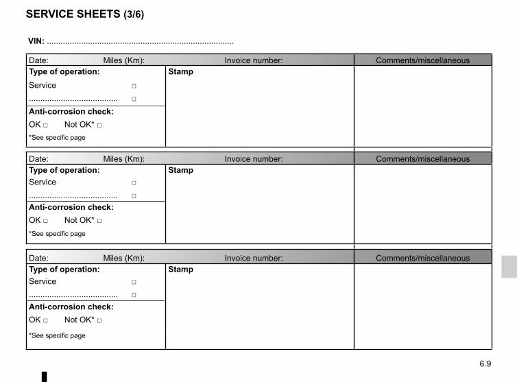
6.9
SERVICE SHEETS (3/6)
VIN: ..................................................................................
Date: Miles (Km): Invoice number: Comments/miscellaneousType of operation: StampService □....................................... □Anti-corrosion check:OK □ Not OK* □*See specific page
Date: Miles (Km): Invoice number: Comments/miscellaneousType of operation: StampService □....................................... □Anti-corrosion check:OK □ Not OK* □*See specific page
Date: Miles (Km): Invoice number: Comments/miscellaneousType of operation: StampService □....................................... □Anti-corrosion check:OK □ Not OK* □
*See specific page

6.10
SERVICE SHEETS (4/6)
VIN: ..................................................................................
Date: Miles (Km): Invoice number: Comments/miscellaneousType of operation: StampService □....................................... □Anti-corrosion check:OK □ Not OK* □*See specific page
Date: Miles (Km): Invoice number: Comments/miscellaneousType of operation: StampService □....................................... □Anti-corrosion check:OK □ Not OK* □*See specific page
Date: Miles (Km): Invoice number: Comments/miscellaneousType of operation: StampService □....................................... □Anti-corrosion check:OK □ Not OK* □
*See specific page

6.11
SERVICE SHEETS (5/6)
VIN: ..................................................................................
Date: Miles (Km): Invoice number: Comments/miscellaneousType of operation: StampService □....................................... □Anti-corrosion check:OK □ Not OK* □*See specific page
Date: Miles (Km): Invoice number: Comments/miscellaneousType of operation: StampService □....................................... □Anti-corrosion check:OK □ Not OK* □*See specific page
Date: Miles (Km): Invoice number: Comments/miscellaneousType of operation: StampService □....................................... □Anti-corrosion check:OK □ Not OK* □
*See specific page

6.12
VIN: ..................................................................................
Date: Miles (Km): Invoice number: Comments/miscellaneousType of operation: StampService □....................................... □Anti-corrosion check:OK □ Not OK* □*See specific page
Date: Miles (Km): Invoice number: Comments/miscellaneousType of operation: StampService □....................................... □Anti-corrosion check:OK □ Not OK* □*See specific page
Date: Miles (Km): Invoice number: Comments/miscellaneousType of operation: StampService □....................................... □Anti-corrosion check:OK □ Not OK* □
*See specific page
SERVICE SHEETS (6/6)

6.13
ANTICORROSION CHECK (1/6)
If the continuation of the warranty is subject to repair, it is indicated below.
VIN: ..........................................................
Corrosion repair operation to be carried out:
Stamp
Date of repair:
Repair to be carried out: Stamp
Date of repair:
Repair to be carried out: Stamp
Date of repair:
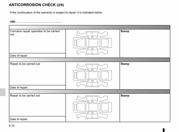
6.14
ANTICORROSION CHECK (2/6)
If the continuation of the warranty is subject to repair, it is indicated below.
VIN: ..........................................................
Corrosion repair operation to be carried out:
Stamp
Date of repair:
Repair to be carried out: Stamp
Date of repair:
Repair to be carried out: Stamp
Date of repair:

6.15
ANTICORROSION CHECK (3/6)
If the continuation of the warranty is subject to repair, it is indicated below.
VIN: ..........................................................
Corrosion repair operation to be carried out:
Stamp
Date of repair:
Repair to be carried out: Stamp
Date of repair:
Repair to be carried out: Stamp
Date of repair:

6.16
ANTICORROSION CHECK (4/6)
If the continuation of the warranty is subject to repair, it is indicated below.
VIN: ..........................................................
Corrosion repair operation to be carried out:
Stamp
Date of repair:
Repair to be carried out: Stamp
Date of repair:
Repair to be carried out: Stamp
Date of repair:

6.17
ANTICORROSION CHECK (5/6)
If the continuation of the warranty is subject to repair, it is indicated below.
VIN: ..........................................................
Corrosion repair operation to be carried out:
Stamp
Date of repair:
Repair to be carried out: Stamp
Date of repair:
Repair to be carried out: Stamp
Date of repair:

6.18
ANTICORROSION CHECK (6/6)
If the continuation of the warranty is subject to repair, it is indicated below.
VIN: ..........................................................
Corrosion repair operation to be carried out:
Stamp
Date of repair:
Repair to be carried out: Stamp
Date of repair:
Repair to be carried out: Stamp
Date of repair:
7.1
ALPHABETICAL INDEX (1/5)AABS .........................................................................2.9 → 2.12accessories........................................................................ 5.26accessories socket ............................................................ 3.19additional methods of restraint .....................1.29 → 1.32, 1.35
side protection ............................................................. 1.34to the front seat belts .......................................1.29 → 1.32to the rear seat belts ........................................1.29 → 1.33
adjusting your driving position ....................... 1.22 – 1.23, 1.26air bag....................................................................1.29 → 1.35
activating the front passenger air bags ........................ 1.48deactivating the front passenger air bags .................... 1.46
air conditioning .................................................3.4 → 3.8, 3.11air vents ...................................................................... 3.2 – 3.3anti-corrosion check ..............................................6.13 → 6.18anti-corrosion protection ...................................................... 4.9anti-lock braking system: ABS .................................2.9 → 2.12armrest:
front .............................................................................. 3.17ashtray ............................................................................... 3.19ASR (traction control) ..............................................2.9 → 2.12audible and visual signals.................................................. 1.70
Bbattery................................................................................ 1.5512 volt battery
breakdown recovery ......................................... 5.23 – 5.24maintenance ......................................................... 4.6 – 4.7
12 volt battery ........................1.2 → 1.6, 4.6 – 4.7, 5.23 – 5.24battery (remote control) ..................................................... 5.25bonnet......................................................................... 4.2 – 4.3brake fluid ............................................................................ 4.5bulbs
changing ..........................................................5.14 → 5.18
Ccentral door locking ...............................................1.19 → 1.21changing a bulb .....................................................5.14 → 5.18changing a wheel...................................................... 5.9 – 5.10changing gear ............................................................. 2.3 – 2.4charge meter .............................................................. 1.58, 2.8charging cord ...........................................................1.8 → 1.13charging flap ............................................................1.7 → 1.13charging socket .....................................1.2 → 1.6, 1.8 → 1.13child restraint/seat .............................1.37 – 1.38, 1.40 → 1.48child safety.......................1.15, 1.37 – 1.38, 1.40 → 1.48, 3.12child seats..........................................1.37 – 1.38, 1.40 → 1.45children ...................................... 1.15, 1.17 – 1.18, 1.37 – 1.38children (safety) ................................................................. 3.12cigar lighter ........................................................................ 3.19cleaning:
inside the vehicle .............................................. 4.11 – 4.12clock .................................................................................. 1.49closing the doors ...................................................1.17 → 1.20connected services .............................................................. 1.3control instruments ................................................1.54 → 1.60controls ..................................................................1.50 → 1.53coolant ................................................................................. 4.4courtesy light ...................................... 3.14 – 3.15, 5.19 – 5.20courtesy mirrors ................................................................. 3.15cruise control ................................................1.55, 2.13 → 2.19cruise control-speed limiter....................................2.13 → 2.19customised vehicle settings .............................................. 1.68customising the vehicle settings ....................................... 1.68
Ddashboard..............................................................1.50 → 1.53daytime running lights........................................................ 1.71display ...................................................................1.54 → 1.58doors.............................................................. 1.17 – 1.18, 1.21doors/tailgate ................................................. 1.17 – 1.18, 1.21

7.2
ALPHABETICAL INDEX (2/5)driver’s position .....................................................1.50 → 1.56driving ....................................................2.2 → 2.6, 2.9 → 2.21driving position
settings ............................................................1.26 → 1.28
Eelectric beam height adjustment ........................................ 1.74»400 volt» electrical circuit ........................................1.2 → 1.7electric vehicle
vehicle range ........................................................ 2.5 – 2.6noise .............................................................................. 1.6charge ................................................................1.8 → 1.13driving ............................................................ 1.6, 2.5 – 2.6quick change of traction battery ................................... 1.14presentation .........................................................1.2 → 1.6important recommendations ................................... 1.7, 1.9
electric windows ..................................................... 3.12 – 3.13electrical installation ............................................................ 1.9Electronic Stability Program: ESP ...........................2.9 → 2.12emergency brake assist...........................................2.9 → 2.12emergency braking ..................................................2.9 → 2.12energy
recovery ......................................................................... 2.8saving ............................................................................ 2.5charge meter (function) .................................................. 2.8consumption .................................................................. 2.8
energy saving ............................................................. 2.5 – 2.6energy consumption ............................... 1.57 – 1.58, 2.5 – 2.6energy recovery ................................................................... 2.5engine specifications ........................................................... 6.3environment ......................................................................... 2.7ESP: Electronic Stability Program ...........................2.9 → 2.12external temperature ......................................................... 1.49
Ffaults
operating faults ................................................5.31 → 5.34fittings ....................................................................3.16 → 3.18fog lights ............................................................................ 5.16front passenger air bag deactivation ................................. 1.46front seat adjustment ......................................................... 1.25front seats
adjustment ...................................1.22 – 1.23, 1.25 → 1.28with manual controls .................................................... 1.25
fuses ....................................................................... 5.21 – 5.22
Ggear lever.................................................................... 2.3 – 2.4glove box ........................................................................... 3.18
Hhandbrake............................................................................ 2.4hands-free telephone integrated control ............................ 3.22hazard warning lights signal ................................... 1.70 – 1.71headlight beam adjustment ............................................... 1.74headlight flashers .............................................................. 1.70headlight washer ............................................................... 1.76headrest.................................................................1.22 → 1.24heating and air conditioning system .................................. 3.11heating, air conditioning: programming ............. 2.6, 3.9 – 3.10heating system ........................................................3.4 → 3.10heating/air conditioning programming ...................... 3.9 – 3.10horn ................................................................................... 1.70horn:
flash ............................................................................. 1.70sounding the horn ........................................................ 1.70
hubcap tool .......................................................................... 5.3
Iindicators .................................................................. 1.70, 5.14

7.3
ALPHABETICAL INDEX (3/5)indicators:
direction indicators ....................................................... 1.70exterior temperature indicator ...................................... 1.49instrument panel ..............................................1.54 → 1.60
instrument panel ...........................................1.54 → 1.67, 1.71instrument panel messages...................................1.59 → 1.67interior trim
maintenance ..................................................... 4.11 – 4.12
Jjack ...................................................................................... 5.3
Kkeys ........................................................................ 1.15 – 1.16
Llevels:
brake fluid ...................................................................... 4.5coolant ........................................................................... 4.4windscreen washer reservoir ......................................... 4.5
lifting the vehiclechanging a wheel ................................................ 5.9 – 5.10
lighting:exterior .............................................................1.71 → 1.73instrument panel .......................................................... 1.71interior ........................................... 3.14 – 3.15, 5.19 – 5.20
lightsadditional ..................................................................... 5.16adjustment ................................................................... 1.74changing bulbs .................................................. 5.14 – 5.15fog lights ...................................................................... 5.16front ................................................................... 5.14 – 5.15
lights:adjusting ...................................................................... 1.74brake lights ....................................................... 5.17 – 5.18dipped beam headlights ............................. 1.54, 1.71, 5.15
direction indicators ............................ 1.54, 1.70, 5.14, 5.17fog lights ........................................... 1.54, 1.73, 5.16, 5.18hazard warning ............................................................ 1.70indicator lights .............................................................. 5.18main beam headlights ................................ 1.54, 1.72, 5.15number plate lights ...................................................... 5.18reversing lights ............................................................. 5.18side lights ................................................... 1.71, 5.15, 5.17
locking the doors ..........................................1.15 → 1.18, 1.21
Mmaintenance:
bodywork ............................................................ 4.9 – 4.10interior trim ........................................................ 4.11 – 4.12mechanical .........................................4.2 – 4.3, 6.7 → 6.12
map reading lights .................................................. 3.14 – 3.15menu for customising the vehicle settings ......................... 1.68methods of restraint in addition to the seat belts ...1.29 → 1.35multimedia equipment ....................................................... 3.22
Nnavigation .......................................................................... 3.22navigation system .............................................................. 3.22
Oopening the doors ..................................................1.17 → 1.20operating faults .............................................1.66, 5.31 → 5.34
Ppaintwork
maintenance ....................................................... 4.9 – 4.10parking distance control.......................................... 2.20 – 2.21power-assisted steering..................................................... 1.36practical advice ........................................................... 2.5 – 2.6pretensioners .........................................................1.29 → 1.32puncture.................................................................... 5.9 – 5.10

7.4
ALPHABETICAL INDEX (4/5)QQuickdrop (system) ........................................................... 1.14
Rradio................................................................................... 3.22rear view mirrors ................................................................ 1.69RENAULT ANTI-INTRUDER DEVICE (RAID) ................... 1.21replacement parts ................................................................ 6.6reverse gear
selecting ................................................................ 2.3 – 2.4reversing sensor ..................................................... 2.20 – 2.21roof bars ............................................................................ 3.21roof rack
roof bars ....................................................................... 3.21
Sseat belt pretensioners ..........................................1.29 → 1.32
front seat belt ...................................................1.29 → 1.32seat belts ..................................1.26 → 1.32, 1.34 – 1.35, 1.55see-me-home lighting ............................................... 1.72, 1.74service sheets..........................................................6.7 → 6.12side protection devices ...................................................... 1.34signals and lights ...................................................1.71 → 1.74speed control .............................................................. 2.3 – 2.4speed limiter .................................................1.55, 2.13 → 2.15starting ................................................................................. 2.2starting the engine ............................................................... 2.2steering wheel
adjustment ................................................................... 1.36stopping the engine ............................................................. 2.2storage compartment.............................................3.16 → 3.18storage compartments ...........................................3.16 → 3.18sun visor ............................................................................ 3.15
Ttailgate ............................................................................... 3.20
tanks and reservoirsbrake fluid ...................................................................... 4.5coolant ........................................................................... 4.4
tanks and reservoirs:windscreen washer ........................................................ 4.5
technical specifications ........................................................ 6.6telephone ........................................................................... 3.22temperature regulation ..............................................3.4 → 3.8tool kit ......................................................................... 5.2 – 5.3towing
in the event of energy failure ...........................5.28 → 5.30breakdown .......................................................5.28 → 5.30
towing hitch...................................................... 5.3, 5.29 – 5.30towing rings ............................................................ 1.40 – 1.41traction battery ...........................................................1.2 → 1.7traction battery charge .............................................1.8 → 1.13traction control: ASR ................................................2.9 → 2.12transporting children ..........................1.37 – 1.38, 1.40 → 1.48transporting objects
in the luggage compartment ........................................ 3.20trims ..................................................................................... 5.3trip computer and warning system.........................1.59 → 1.67tyre inflation kit....................................................5.2, 5.4 → 5.8tyre pressure............................................................... 4.8, 5.12tyre pressures ...................................................................... 4.8tyres ................................................................4.8, 5.11 → 5.13
Uunlocking the doors ................................................ 1.19 – 1.20
Vvehicle range .............................................................. 2.5 – 2.6ventilation ..................................................................3.4 → 3.8
Wwarning buzzer ................................................ 1.17, 1.70, 1.72

7.5
ALPHABETICAL INDEX (5/5)warning lights.....................................1.54 → 1.56, 1.59 – 1.60washing .................................................................... 4.9 – 4.10weights ................................................................................ 6.4wheelbrace .......................................................................... 5.3wheels (safety) ......................................................5.11 → 5.13windscreen washer .......................................... 1.75 – 1.76, 4.5windscreen washer/wiper ....................................... 1.75 – 1.76wiper blades ...................................................................... 5.27wipers ..................................................................... 1.75 – 1.76
blades .......................................................................... 5.27


à999106490Rïêìä T0RENAULT S.A.S. SOCIÉTÉ PAR ACTIONS SIMPLIFIÉE AU CAPITAL DE 533 941 113 € / 13-15, QUAI LE GALLO 92100 BOULOGNE-BILLANCOURT R.C.S. NANTERRE 780 129 987 — SIRET 780 129 987 03591 / TÉL. : 0810 40 50 60
NU 914-4 – 99 91 064 90R – 08/2012 – Edition anglaise
FLUENCEFLUENCE Z.E.Z.E.
( www.e-guide.renault.com )