flr300l»l2 - us environmental protection agency. excavation and soil washing by froth flotation, 2....
TRANSCRIPT

WESTON WAYWEST CHESTER, PA 19380PHONE: 215-692-3030TELEX: 83-5348
MANAGES \ S OESX ERS ONSULTANTS
February 3, 1987
Ms. Laura BoornazianU.S. Environmental Protection Agency841 Chestnut Building _6th FloorPhiladelphia, PA 19107
Project: EPA Contract No. 68-01-6939
Document No.: 252-RI2-EP-DWH
Subject: Bench-Scale/Pilot StudiesL. A. Clarke Site
Dear Laura: - — -
Even before the promulgation of SARA, the REM II team waspursuing the use of .Innovative treatment technologies forremediation of the L. A. Clarke site. By way of 1 iteraturereview, in-house research, interviews with companyrepresentatives and technology transfer sessions, we havetargeted several techniques for which bench-scale pilot study iswarranted to establish performance and cost data,
These specific techniques are briefly presented below bytreatment technology category. Further details concerning thesetechniques may be found in the respective company literatureaccompanying this letter.
(3.) In-Situ Soil FlushingThe APS SystemMTA Remedial Resources, Inc.1511 Washington AvenueGolden, CO 80401
The APS (alkaline agents, polymers, surfactants) 'system is aresult of technology transfers from the enhanced oilrecovery business. Alkaline agents are used to 'liberatecontaminants from mineral particles. Polymers are used tocontrol the mobility of the injected flui&/contaminantsolution and surfactants are used to emulsify thecontaminants.
flR300l»l2
Ms. Laura Boornazian February 3, 1987Doc. Control No.: 252-RI2-EP-DWH Page 2
MTARRI conducts a feasibility program culminating in a fieldpilot scale test for approximately $100,000. In such atest, one injection well is installed, fluids injected, anda series of soil borings conducted to monitor results.Approximately 3 months of laboratory work is required priorto on-site testing.
(2) Soil Washing __.MTA Remedial Resources, Inc.1511 Washington AvenueGolden, CO 80401
Contaminant liberation from clays and sands is accomplishedthrough alkaline and surfactant addition which results inclay dispersion and change in the interfacial tension. Afroth floatation machine, common to the mineral business,physically separates .. and ..concentrates the contaminants inthe froth which is skimmed off.
MTARRI will conduct a 2-6 month lab evaluation for$10-$60,000 (plus analytical costs) and establish an on-sitepilot scale facility for $750,000.
(3) SolidificationSoliditech, Inc.99 Detering, Suite 230Houston, Texas 77007
Solidification of materials with high organic content hasbeen a problem. Soliditech has developed a process thatsolidifies a wide range of organic materials. This processutilizes a chemical" reagent and pozzolanic materials such asfly ash, kiln dust, etc., that prevents the "flash" settingthat can occur and enhances the hydration leading higherstructural strength. A sample of solidified L. A. Clarkecreosote-soaked soil was shown to you at our 16 December1986 meeting.
In addition to these promising technologies,, other innovativeschemes are being researched. A recent report on ultrafiltrationof creosote-containing wastewater indicates the possibleapplication of_ this__technique. Other techniques underconsideration include bioreclamation (several firms includingECOVA, LOMA, and REXNORD were contacted and interviewed),
flR300i*J3
Ms. Laura Boornazian February 3, 1987Doc. Control No.: 252-RI2-EP-DWH Page 3
incorporation o'f creosote-contaminated soils in roadway asphaltsand innovative thermal treatments such as the Shirco Infra-redincinerator. And as you are aware, WESTON is about to undertakea bioreclamation bench-scale treatability study.
While these technologies do fall within generic categories (i.e.,solidification, soil flushing, incineration, etc.), they may beproprietary and thus only obtainable from one company. As aresult, procurement would have to be on a sole-source basis.Hopefully this hurdle can be overcome within the BOA-qualifiedsubcontractor process recently established for EPA andadministered by CDM.
It is still unclear what level of cleanup will be required interms of quantity or type of technology. This decision willresult from the iterative process of screening alternativeremediation schemes and on action levels identified in the publichealth ©valuation. However, we feel that it is important toscrutinize these techniques now so that we can incorporate theinformation into the decision process.
Please give me a call, if you have any questions.
Sincerely yours,
ROY F. WESTON, INC.
AShapot
Project Manager
RMS:sd
cc: E. ShoenerG. AnastosG. JohnsonD. DworkinNPMO Document Control
flRSOOMU

MTA Remedial Resources, Inc.1511 Washington Ave., Golden, CO 80401 Telephone (303) 279-4255
November 24, 1986 «<0y f.
Mr. Neil RiversMr, Daniel Dw rkin £)££ | jgocWeston Way -- -Westchester, PA 9380 Rete/Vfd 0y
Dear Nell/Daniel; "HW MgmL
Thank you for taking your time to meet with me and to discuss MTARRI'salternative technologies applicable to creosote contaminated sites.
As I mentioned to you, we have previous experience in creosote contaminantremoval utilizing either one of two systems:
1. excavation and soil washing by froth flotation,
2. in-situ soil wash using the APS system.
Lab testing of both systems has been conducted on 2 different creosotecontaminated sites. Currently, we are designing a field, program using the APSsystem on a 140 acre, 10 ft. deep, creosote/free oil/pentachlorophenal. site inregion VIII. The concept has been presented to the region VIII regulatoryagency. They have not officially signed off but we are proceeding with allindication that they will sign off."
_. . _ - —-3 — -----Assuming 500,QUO yards of contaminated material, 10:ft. deep, the
following parameters are-projected.
Excavation and Soil Wash ... ..... ,
Cleanup: 99+% 3Operating and Capital Cost: $50 ± 25%/yardCleanup time: 5-10 yearsNet Present Value: 10 years, 200 tons per day, 10% IRR = $15.4 million
In-Situ Soil Wash (No Bioreclamation)
Cleanup: 75-95% " 3Operating and Capital Cost: $15 _+ 25%/yardCleanup time: 5 years -Net Present Value: 5 years, $15/yard , 10% IRR = $6.25 million
In-Situ Soil Wash (following by Bioreclamation) ;. . .. .,
Cleanup: 85-99% AOperating and Capital-Cost: $45 _+ 25%/yardCleanup time: 10 years . * - -- —Net Present Value: 10 years, $45/yard , 10% IRR s $15.3 m:
fiRSOOUS
MTARRI
Mr. Heil RiversMr. Daniel DwarkinNovember 24, 1986Page 2
I have included two proposals that were previously prepared for creosotecontaminated sites. The first proposal deals with in-situ soil wash followedby bioreclamation. Depending upon your soil/aquifer conditions, and thedesires of the regulatory agencies, bioreclamation may or may not be necessary.
The second proposal outlines the cleanup using excavation and frothflotation soil wash. Obviously, quality assurance is much greater with thesecond system, however, one has to be careful of the RCRA vs. CERCLAregulations. If RCRA, the soil must be delisted, again that is achievable bysoil wash but dependent on the nature of the soil and contaminants. IF CERCLA,no delisting is necessary and life is easier under a negotiated consent degreeon how clean is clean.
Again, thanks for your time. I will call you 8 December to discuss thedata I've sent and answer any questions you may have.
I believe our past experience in creosote cleanups could greatly assist :your client.
Sincerely,
.al Resources, Inc.
Paul B. Trost
PBT/ct
MTARRI
ABSTRACT
Aquifer Restorationby
Dr. Paul B. TrostKTARRI
Restoration of aquifers contaminated with aromatic, aliphatic,and/or organochlorides can be, significantly sped up and achieved at lesscost through the usage_.o£-.£PA-approved alkaline ..agents, polymers, andsurfactants (the APS* system).
This APS*— system is a result of direct technology transfers fromthe enhanced oil recovery business. Alkaline agents are used to 1)liberate the contaminants from mineral particles, and 2) as a co-surfactant. Surfactants are .used to 1) substitute for the contaminanton the.clay particle, and 2) emulsify the contaminants. Polyr.ers, suchas biodegradable polysaccharides, achieve .mobility control on theinjected fluids-thereby insuring better sweep sufficiency and a sore -thorough, cleanup. - -
By uslrii *xhe APS* syste-V ith'e number c,f- psre vc!u~es of water t<: betre^ied. cac_£-ererallv. be ..decreased ~bv 507. .Thus, a .sicn-lficant cast - ._
Design of- the "APS*-..systemlo_c.ciir.s in the lab and proceeds to a fieldpilot demonstration prior to full field expansion. This minimizes therisks at each step.
MTARRI
ABSTRACT
Removal of Organic ContaminantsThrough "Soil Washing"
byDr. Stan RickardDr. Paul B. Trost
mm :
An on-site volume reduction technique has been developed to remove andconcentrate organic contaminants from soils. Bench scale results have shownthe soil wash process successful at removing 99.4% toluene, 99.5% gasoline,96.7% diesel, 96.1% kerosene, 97.4% TCE, 99.9% tetrachloroethylene, 99.0%creosote-coal tars (PAH's) at $65/ton +/- -25%. ._._.....
Percent contaminant removal and final operating costs are dependent on 1)relative amounts of clay and sand; 2) nature of contaminant; and 3)concentration and type of reagents.
This patent pending soil wash process utilizes technology, transfers .fromboth the mining and enhanced oil recovery fields, to simultaneously remove andconcentrate the contaminants.
Contaminant liberation fror, clays ar.d sands is accomplished throughalkaline and surfactant addition .which results in 1); clay dispersion: and. 2)
an the Interfacisl ter.5ic-".':viA frorh fictation nachine, corsr.or. to_Lhe^.business, physically separates and concentrates, the contaniaants in the
froth which is skinned off.
Detoxified soil (+/- 90% by weight) can be returned to the site and theconcentrated contaminants (+/- 10% by weight) incinerated, landfilled, orsubjected to UV-ozone treatment for ultimate contaminant removal.
Waste streams tested to date include various fuel hydrocarbons (gasoline,diesel, kerosene), solvent (toluene, benzene, trichloroethylene,tetrachloroethylene), creosote (polynuclear aromatics), pesticides .(.endrin,aldrin), and PCS oils in soils, API separator sludges from refineries have also.been tested with 95% +/- 5% removal of the hydrocarbons from the solids. .. -
Froth flotation equipment is available off-the-shelf and no equipmentdevelopment or manufacturing is necessary.
Process flow rates can vary from 10-1000 .tpd and the equipment can be in amobile (modular) or fixed base form. .
MTARRI
ABSTRACT
Removal of Pb, Cd, Cr, CuThrough "Soil Washing"
byDr. Stan RickardDr. Paul B. Trost
HTARRI
Greater than 99+% of Cu , Cd, , Cr , Cr , _Pb _ , Ni has been removedfrom contaminated soils using MTA Remedial Resources, Inc.'s (MTARRI) "soilwash" process, __ - _ . . _ . - - - - - -
The "soil wash" process is a result of. technology transfer from the miningbusiness. Operating rates of 10-5,000 tons per day can be achieved. Projectedoperating and capital costs are $65 +_ $25 per ton.
The . technology : employed,, .counter, cur r eat washing (decantation), utilizes asuitable .solubilizinV^agent" X"lixivant") for the metals, . After the metals ares'. .^bj !i2_e5- cc*jr.ts.r .current tloi:_ in commercially available thickeners is u£ed•_•'• .separate ar.c rer.ove the.solubilized" metals fror. the_soil _~l-p.eral particles.Cli=r£^<?d = i.Ls are" returned to tfce -site. Process crater is recycled during therf: *.it:L£L ;2-.th. ihc .,~eials,. being removed by revirs"e""T;"S s"i~'," l:r. exchange anu""'o:i:
:.re-;:"fri"t£: n.. " ir ^ d'Is-ch arge Vate'r. will meet... l FOES or" sever ..dischargerccjiireTzents. " - '-. "~~-> ; --—T"- — •- ------- - : --;_—_ ———' " " -
All equipment "is" commercially available and are 'off-the-shelf itens.Testing and process development is slightly site.specific, but generally doesnot present a major time/cost factor.
flR300UI9

SOLIDITECH, INC99 DETERINGSUITE 230
HOUSTON, TEXAS 77007
TELEPHONE:713/864-419:
TELEX: 4620087FAX: 713/875-2990
DESCRIPTION OF ?2S SOLIDIFICATION PROCESS
UNITED RESOURCE RECOVERY, INC.
INTRODUCTION
Disposal of hazardous chemical waste in the United Statesin the past has in large part consisted of either burying thewaste streams or placing the wastes in liquid or slurry form inlandfills, pits, ponds or impoundments. The latter practice hasresulted in wide spread pollution and contamination of surfaceand groundwater resources and exposure to people from contact andinhalation. The United States Environmental Protection Agency haspromulgated extensive and comprehensive regulations to control themanagement of hazardous waste, particularly organic wastes, because •of the difficulty of -dealing with the latter waste streams.
SOLIDIFICATION TECHNOLOGY
The 1984 Amendments to the Resource Conservation and RecoveryAct of 1976 contains provisions that no free liquids, particularlyorganic liquids, could be placed in landfills or land disposal fac-ilities. Strict groundwater standards also mandate that no pol-lutants migrate outside the unit boundary at a management facility.
Solidification of organic materials has been a particular chal-lenge to researchers. Recently a process was developed that doessolidify a very broad range of organic materials that utilizesa chemical reagent and pozzolanic matterials such as fly ash, kilndust, steel or lead smelter baghouse dust.
Pozzolanic materials have been used in the past for solidifica-tion purposes but not very successfully with organics. Likewise,Portland cement has been used but with disappointing results withorganics. The present technology uses a chemical reagent that bothprevents some of the disagreeable characteris£ics of pozzolans suchas "flash" setting and yet enhances the agreeable characteristicssuch as hydration and matrix formation leading to-significant struc-tural strength.
HR30Q1+20

The process uses the concept of microblending and micro-encapsulations. Microblending is the process of mixing the re-agent into the waste streams in such a manner that the reagentis thoroughly dispersed throughout. Microencapsulation occursin part by the cross-linking of organic and inorganic particlesin the mass through a five phase cementation process. The mix-ing provides for a coating of the large particles by the cemen-tation products of the pozzolans and the sealing of that portionof the matrix containing micropores and spaces. This sealingprocess results^ in a significant reduction in leaching potential.
The formulation of the reagent can be modified to a specificwaste to optimize the chemical reaction and resulting characterof the solidified waste. Some waste materials will function as achemical reagent in the reaction and actually contribute to thephysical hardening and leaching characteristics. The time forset up of the stream can be controlled to a certain degree by theaddition of retarders or accelerators.
The solidification process has been shown to be an economicalmethod of fixing and stabilizing a difficult class of waste andpreventing it from mobilizing and dispersing into the environment.Coupled with the concept of secure containment either by surround-ing or encapsulating walls such as slurry walls or disposal insecure geologic contamination structures such as salt formations,the technology offers a very secure disposal option for organicmaterials.
flR300l*2

PROPOSAL
lor
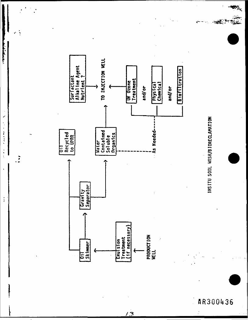
IHSITU SOIL VASH INTEGRATED
VITH INSITU BIORECLAMATION AND ENGINEERED
BIORECLAMATION STUDIES
to
CH2M HILL - UPRR SITE
IN RESPONSE TO
12 AUGUST, 1986 CH2M HILL RPP
Respondents
THE MTARRI TEAK
HTARRI
Keystone Environmental Services
SURTEK
Baski Water Instrument*
flR30Qi*22
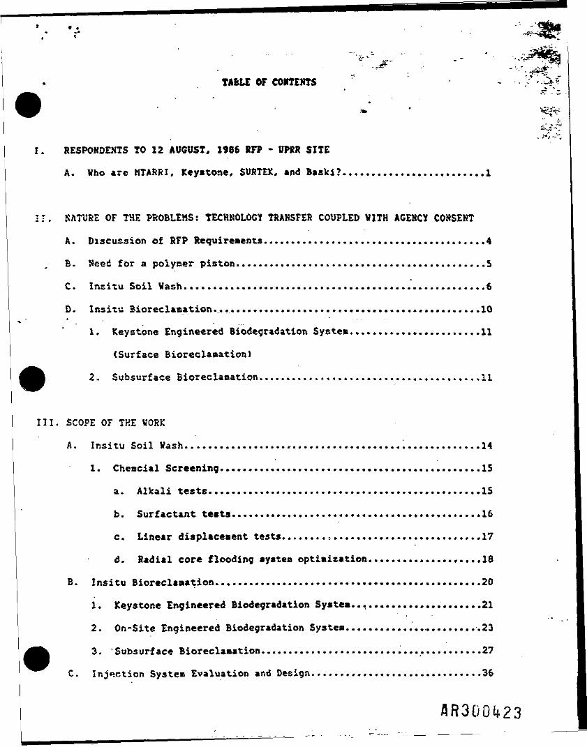
TABLE OF CONTENTS
I. RESPONDENTS TO 12 AUGUST, J986 RFP - UPRR SITE
A. Vho are MTARRI, Keystone, SURTEK, and Baski?.........................1
•I. NATURE OF THE PROBLEMS: TECHNOLOGY TRANSFER COUPLED WITH AGENCY CONSENT
A. Discussion of RFP Requirement*.......................................4
B. Need for a polymer piston............................................S
C. Insitu Soil Vash.....................................................6
D. Insitu Bioreclamation...............................................10
1. Keystone Engineered Biodegradation System.......................11
(Surface Bioreclanation)
2. Subsurface Bioreclamation...................................... .11
III. SCOPE OF THE VORK
A. Insitu Soil Vash....................................................14
1. Chencial Screening..............................................15
a. Alkali tests. ...............................................15
b. Surfactant tests........................................... .16
c. Linear displacement tests..................................17
d. Radial core flooding systea optimization...................,18
B. Insitu Bioreclamation............................................... 20
1. Keystone Engineered Biodegradation System....................... 21
2. On-Site Engineered Biodegradation Systen........................23
3. 'Subsurface Bioreclanation.......................................27
C. Injection Systea Evaluation and Design..............................36

f-V. ADM1HISTRATIOH/OSGAKI2AT10N
A. QA/OC and Safety
B. Project Management
C. Reporting
>
V. COST SECTION................................. ...........................41
VI APPENDICES
A. Schedule
B. Resumes
C. Teas Members
Project Summaries
D. Analytical Methods
• E. OA/QC Plan

Keystone Environmental Resources, Inc., a Delaware corporation, is a full
range environmental services company with consulting, analytical, and remedial
tction capabilities. Keystone is * wholly ovned subsidiary of Coppers Company,
Inc., a *1.6 billion/year corporation with construction material and services,
chemicals, and wood treating business units. Keystone has extensive experience
associated with the environmental situations of wood treating facilities which
include creosote, pentachlorophenol, and copper-arsenic-chrome. Keystone i« a
leader in providing environmental services to the wood treating industry.
Keystone provides project-oriented reaedial action services, based on their
extensive experience of over 200 completed projects, at devising low cost
solutions. Keystone has developed, field tested, and installed proprietary
cleanup techniques utilizing biological, checical, and physical technological
advances to achieve low cost, state-of-the-art cleanups. Please see Keystone's
Stateoent of Qualifications delivered under separate cover.
SURTEK, a Colorado corporation located at 1511 Washington Ave., Golden,
CO, is a recognized leader in the .enhanced oil recovery (EOR) field. SURTEK
has laboratory designed chemical recovery systems for over 250 projects ranging
from consolidated to unconaolidated materials. These chemical designed systeos
are then flow tested in the laboratory utilizing both linear and radial core
floods to simulate actual field conditions. Core flood results are employed to
design a pilot test with reservoir engineers and reservoir geologists input to
insure a successful project. SURTEK'* prior experience in dealing with heavy
oils and tar sands, combined with its knowledge of two phase flow behavior will
provide the maximum technology transfer to this proposed project.

Baski Vattr Instruments, a Lakewood, Colorado based hydrogtology and
manufacturing company, has field operational experience in hydrogeology, a
design and completion of water wells. Baski has shown to bt an industry leader
in the design, manufacturing, and utilization of new and innovative systems tor
veil completions? such as air inflatable packers, and pitless adapters. Baski
will provide veil (or trench) completion techniques for the project team
together with hydrogeological expertise.
Thus, the MTARRI project team will provide personnel experienced in a vide
range of vood treating chemicals (e.g. creosote, pentachlorophenol, CCA) to
achieve CD state-of-the-art technology transfers; (2) successful lab and pilot
test design and execution; (3) engineers experienced in two phase fluid flow
and in bioreclamation to assist, as necessary, with government agency
presentation for the structuring of a consent decree; and £4) successful,
cost execution of the project.
12. NATURE OF THE K081EM: TECHNOLOGY TRANSFER COUPLED WITH AGEKCY CONSENT
CH2M Kill'* KFP of 12 August, 1966 seeks cost effective, technologically
advanced systems to meet ground water protection standards for the unconfined
aquifers contaminated with various hydrocarbons. To achieve these cost3
effective solutions of insitu soil washing and bioreclamation two additional
problems must be defined and then solved: (1) how can the technology transfers
be integrated and achieved at lowest cost and highest probability of success;
and f2> will the regulatory agencies accept the lab and pilot test data to
allow for a final approval or consent decree.
A. Discussion of RFP Requirements
Bench scale and pilot scale studies are to be performed to design and
desonstrate a cost-effective, insitu cleanup prograo for unconsolidated
alluvj.ua contasinated with polynuclear aromatics, aliphatic and aromatic oils,
pentachlorophenols, and possibly polychlorinated dibenzofurans and
dibenzodioxins. But, as previously noted, to achieve these objectives the
technology transfer must be accomplished by experienced personnel organized as
a multi-disciplined project teaa and capable of interpreting the bench and
pilot data and assist, as necessary, in obtaining regulatory approval.
Furthermore, a history of field operational experience is critical to insure
the design paths being initially proposed and followed will ultimately lead to
a low cost, regulatory acceptable, functional solution.
To accoaplish the technology transfers and obtain regulatory agreement for
demonstrating technical and economical insitu soil wash and biodegradation
, the two technologies uuat be integrated. Jntecrjti««-«* <—--•*„ Soil
flR300<*27
II
wash and insitu biodtgradation is absolutely necessary aince the same injection
system and pilot plant facilities will be utilized. Thus the soil wash a
must be designed and engineered to assure the alluvium's physical parameters
(e.g. permeability, well bore skin damage) and the residual chemical system are
not deleterious to subsequent bioreclamation Involving either the bacteria or
their enzymes. This integration and project assurance will be incorporated
into all work plans and development stages of the project and is the critical
task. Bench scale experiments have been designed in this program to test for
the compatibility of the two aystens at a very early stage. This integration
is the critical technical task.
Keystone has extensive experience in negotiating approval and consent
decree frameworks utilizing novel or innovative technologies with the
regulatory agencies. An example of one such situation demonstrates the us
Keystone's computer-based project management systea in negotiating consent
decree tise frames. If the client so desires this system would be available.
B. Keed for t PolvBcr Piston
The WTAKRI team recognizes CH2M Hill's concerns of: (1) loss of
permeability through pore throat plugging of the aquifer; and (2) possible
negative effect on subsequent insitu bioreclamation if a polymer is utilized.
However, in the teams opinion, the probability of success for insitu soil wash
using a biodegradable food additive polyner will be increased very
significantly. It is difficult to push a steel beaa with a pencil; similar
it is difficult to push the viscous heavy oil with water.
"7

Xanthan gum, a polysaccharidt, is the polymer of choice. Ketchup,
mayonnaise and many other foods contain this polymer as a thickening agent.
Concentration ranges of the xanthan gum would be 500 - 10000 ppm.
The first bench scale test will evaluate these two areas of concern.
Subsequent bench scale testing for insitu soil wash will not utilize this
polysaccharide until -the clients (and agencies ?) concerns are satisfied.
Thus, the project schedule will not be impacted by this first test. Cost of
the xanthan gun test is insignificant when compared to the increased degree o;
cleanup achievable with a biodegradable polymer.
C. Insitu Soil Washing
Transferring EOR technology to aquifer restoration is feasible, however,
certain unique problems will be present. Previous projects by other remedial
action contractors have failed to successfully transfer this technology. For
example, bench scale tests showed a surfactant was very effective at mobilizing
a viscous PCB hydraulic oil. However, field testing was a failure. The reason
for the failure was insufficient knowledge of two phase fluid flow in a medium
which is affected by permeability heterogeneity, relative permeability,
mobility ratio, and interfacial tension, Without personnel experienced in two
phase fluid flow, successful lab or bench scale experiments could similarly
fail in the pilot project or, even worse, in the costly full field expansion
program. The MTARRI teas has this experience to insure successful design and
field implementation.
Produced fluids may b* as emulsions and will contain high concentration:
of contaminants. Emulsions are comaon in the oil business and can be
very successfully. Severe emulsions such as those produced in surfactant oi2
recovery project* have been treated for less than 2 cents/gallon. High
contaminant concentrations in the produced fluids can be readily mitigatedj
using a combination of conventional oil-water separation techniques and
Keystone's past experience and SURTEK'» experience in surfactant flooding.
Definitions (A), effects (B), and solutions (C), of these permeability a
viscosity terms are briefly outlined below.
t1. Permeability <K> Heterogeneity
a. Definition: differences, either vertically or horizontally,in the ability of a rock to conduct fluid.
b. Effects:
1) If vertical and horizontal permeabilities are similar anyinjected fluids would rise to the same degree as theywould horizontally extend. Thus the .injected surfactantwould move up and out of the zone of contamination.
2) Permeability variations with depth would limit fluid flowto one area resulting in only partial cleanup orexcessively long pumping tines.
C. Solution:
1) Use of polyier.
2) Selective well completion and mode of fluid injection.
2. Relative Permeability
a. Definition: the ability of a porous systei to conduct onefluid when one or more fluids are present.
b. Effects: .
1) Water will love through the aquifer faster than oilresulting in a low oil cut at the producing well.
flR300l*30

. >„...-
<> Pore throat size
'-fre P«-.bility.
the t.n,ion.
3. Mobility Ratio
a. Definition: effective permeability of the fluid in a porous•edium divided by the fluid's viscosity.
b. Effects;
1) Rapid breakthrough of the injected fluid through theviscous oil resulting in very low oil cuts at theproducing well. This ia especially problematic if streaksof high permeability are present. See Figure I,
FIGURE I;
Water movementthrough oil.
flRSOOU

2) Injected fluids flow around viscous oil and have verlittle contact mo surfactant addition is very ineffand oil does not move.
3) The higher the mobility ratio number (related to high oilviscosity) poorer will be the performance.
c. Solutions:
1) Lower mobility ratio with biodegradable polymer and/orformulation of a viscous alkaline-surfactant 'plug.*
4. Interfacial Tension
a. Definition: the unbalanced forces acting on a oil droplet incontact with water or a water droplet in contact with oil.
b. Effects:
1) High interfacial tension results in poor movement of theoil by the faster moving water therefore lowering the oilcut at the producing well. For example, attempting to
H . _ wash grease off of the engine block with a stream of*• water. .
2) Low interfacial tension results in the oil droplet bjI : dragged along with the stream of water when a surfacL I ' (soap) is present. For example, washing the grease off(' ' the engine block at a high pressure car wash having soap
in the water.
3) Lowering interfacial tension can mobilize more oil pervolume of water resulting in a higher oil cut at theproducing well.
AR300I+32

D* Inaitu Bioreclamation
Insitu bioreclamation refer* to treatment pertaining to both surface and
subsurface environments.
Surface bioreclamation of organic constituents in the surface soil
involves the application of waste on the soil surface or incorporation of waste
into the upper layer of the soil (zone of incorporation) in order to degrade,
transform or immobilize organic constituents present in the waste. The
biological degradation depends upon the dynamic physical, chemical and
biological process in the treatment zone for success. It is important that the
bioreclamation waste be carefully operated to maintain optimum conditions for
degradation and immobilization of organic constituents, and prevent
environmental contamination.
Subsurface bioreclar-ation involves providing the proper environment to
enhance biological activity and thus increase the rate of contaminant
degradation.
Since insitu bioreclamation is a complicated process, several factors
should be considered:
- waste characteristics;* soil characteristics;* meteorological condition;* operational procedures.
The objective of this insitu bioreclamation program is to evaluate the
feasibility of the insitu bioreclamation for the UPRR Laramie site and to
develop design and operation criteria for a full-scale treatment system. The
study consists of surface bioreclamstion and a subsurface bioreclamationflR300l»33
•valuation and will Include (1) a review of existing information and site
specific data: <2> a laboratory testing program to determine kinetics of
biodegradation; and (3) a possible pilot scale on-site demonstration.
1. Keystone Engineered Biodegradation Systea (Surface Bioreclamation)Keystone engineered biodegradation system (EBDS) consists of a gradedparcel of land on which the treatment process occurs. The upper soillayer is referred to as the zone of incorporation, where the waste isto be cultivated. Additional treatment and immobilization occurs inthe underlying soil which is referred to as the treatment zone.
The objective of this program will be to evaluate the feasibility ofthe EBDS for degradation of wood treating wastes existing in UPRR'cLaraaie site. The proposed project task breakdown and schedule isshown in Appendix A. The investigation will include the following
. subtasks:
a. Evaluate the feasibility of EBDS based on existing siteinvestigation data;
b. Evaluate the meteorological data of the site;c. Characterize the site soil and waste;d. Determine degradation kinetics fro* laboratory testing;e. On-site engineered biodegradation system demonstration;f. Data compilation and report preparation.
2. Subsurface Bioreclaaation
The subsurface bioreclamation described below is an integratedapproach which allows groundwater and contaminated soil to be treatedin place, thereby eliminating the hazards and costs associated withreaoval and transport of contaminated material. The general approachof the subsurface bioreclamation will be: (1) enhancement of existingmicro-organisms; (2) extraction, injection and recycling ofgroundwater; and (3) creation of a biological active barrier.
Naturally occurring microorganisms are capable of metabolizing cany ofthe chemicals that are present in contaminated soil and contaminatedgroundwater if proper conditions are available (Keystone, 1986).Subsurface bioreclamation may be enhanced by providing nutrients,active bacteria seed (if necessary) and oxygen or an electron donorsource e.g. nitrate, hydrogen peroxide, into the subsurface zone ofcontamination via an injection well or infiltration systems. Keystone(1986) has demonstrated that pentachlorophenol, phenolica, andpolynuclear aromatic hydrocarbons can be degraded via a biologicaldegradation systea. • .
Alternative methods of the subsurface bioreclamation may include (1)extracting or flushing out organic and inorganic contaminants viainsitu soil washing process; (2) extracting contaminated groundwatvia a series of pumping veils; (3) pumping the
IThe objective of
c ti i
n ,„ th,I : "" syswrss r-r- •— .
— " -
*=&t
c*9 Al *•>-J C CV **•* Of«g - «
3^-3
1.O
t.O
O
o
! °i •—i! £i 5o> S
*•• *J -%, h ^ > «ri ^ hCD
IQ«- s.> 10fQU OJ
CO
OCO
CO
o to4 ————
coVI_ELkl
14-* VIC «lV LJSCIC«
b f-h- -
oce
III. SCOPE OF V08K
Schedule J, in Appendix A, shows the duration of the bench scale testing
for both insitu soil wash and bioreclamation, projected times for pilot plant
design, and pilot plant construction are also shown on the schedule. A
critical path is shown and is the initial bench and core flooding experiments
so that the same materials can be integrated into the bioreclamation tests.
*MTARRI is currently integrating its field operational capabilities and
soil wash techniques with Keystone's bioreclanation and water treatment
capabilities. Thus, both parties are familiar with working together. SURTEK
and MTARRI have worked together for the past 5 years and, in fact, are located
in the saoe office building. As seen in Dr. Trost'a resume, he was a co-
founder of SURTEK in 1978. MTARRI has utilized the services of Baski Water
Instruments for hydrogeologic testing and varied well completion techniques.
Baski has also been involved in the construction and oodification of radial
core holders for SURTEK. Thus, the team integration involving both corporate
activities and technical interactions is already in place and functional.
The KTARRI project teaa collectively has over 110 professional team
members including geologists, hydrologists, chemists, petroleua engineers,
mechanical engineers, civil engineers, geocheaists, chemical engineers and
environmental engineers that can be called upon as necessary to insure the
successful application of these transferred technologies.
A. Insitu Soil Vash
Fresh contaminated soil sanples will be required for these
Sufficient soil to yield 1 gallon of hydrocarbon contaminant vill be extracted
using dichloromethane followed by solvent evaporation and weighing. The1
density, viscosity and total acid number of the neat hydrocarbon contaminanti
vill be determined* KTARRI has previous experience with UPRR creosote samples
using dichloromethane extraction as a low cost analytical screening method.j
This low cost screening method will be used for the early coreflood
tests. EPA approved, quantitative analyses of the residual contaminant and
produced fluids will be used to characterize the final system designs.
1. Cheirical Screening
a. Alkali tests - Initially, various SiO./Na.O ratio silicateswill be considered as previously defined Ey KTARRI's work withsaaples fron the UPRR Laramie site. On the basis of SURTEK'sexperience vith alkaline systea design, Ka CO., NH OH, ancvarious alkaline potassium salts vill also be considered.
When in contact vith certain hydrocarbon tixtures, thealkaline agents can react to forr, surfactants via asaponificttion reaction. Because these surfactants arecreated at the aqueous-hydrocarbon interface, they can be veryeffective at reducing the interfacial tension (IFT). Tvotypes of tests will be used to evaluate the various alkalinesystems. First, IFT will be tested directly. Second, thephase behavior of varying ratios of hydrocarbon, groundwaterand alkali vill be tested.
1) IFT - Assuming the hydrocarbon contaminant is more densethan water, conventional spinning drop evaluations willnot be possible. This is due to the fact that thehydrocarbon would have to be the external phase and due toits dark color, would not permit measurement of theinternal spinning aqueous phase. Although the pendantdrop technique could technically be used in this case, itscost would be prohibitive for screening large numbers ofsystems.
A si»ple, qualitative drop characterization techniquedeveloped by SURTEK will be used for these evaluations.SURTEK has successfully used this procedure many timesthe evaluation of heavier oils. In this test, the aque
AR3UOi*38
phase serves as the continuous phase in a capillary tube.A drop of the hydrocarbon contaminant is then added to thetube and its physical characteristics noted and related tothe IFT.
The evaluation sequence will be:
a. For each alkali type, determine IFT characteristics_ . -for a range of alkali concentrations (about 0,1 -
5.0 vt.I).
b. For encouraging (low) IFT systems, additional lowconcentrations of salt (NaCl) or surfactant will beadded in an attempt to further reduce the IFT.
2) Phase Behavior - Because these evaluations requireconsiderably more time than the previous IFT tests, onlythe most encouraging systems from the IFT tests will befurther evaluated here. Phase behavior is closely relatedto IFT, yet with these tests, we can also incorporate the.effects of oil-aqueous phase volume ratios, groundwater-salinity interactions, soil influence, and time.
For each parameter tested, a series of test tubes withhydrocarbon contaminant,, aqueous alkali and a sample ofthe alluviuffi vill be blended.
The series will reflect a trend in the parameter beingevaluated. These parameters vill include:
* Alkali concentration;* Salinity;* Surfactant level (limit to less than 0.5 vt.I);* fiydrocarbon-groundwater alkali volume ratio.
The results will be reported as phase types and volumes.Vhere middle phases are formed, an attempt will be cade todetermine the viscosity of this phase. If the phase iswater-external, it is possible that a substantialreduction of the effective hydrocarbon viscosity couldresult. This could yield a substantial improvement in thesystem's hydrocarbon recovery potential.
Surfactant Tests - Biodegradable surfactant concentrationsranging from about 0.5 wt.X to 10 wt.X will be evaluated. Atthese concentrations, good IFT reduction can occur. At thehigher concentrations, inherent viscosity for the injectedfluids can also be created by formation of micellar systems.
The same IFT and phase behavior concepts and procedures thatwere used for the alkaline systems apply in most cases tothese surfactant systems, as veil. Specifically, evaluationsequences vill involve:

s> ina. For each surfactant type, determine IFT
characteristics for a range of surfactant. concentrations.
b. Repeat with selected surfactant blends.
c. For encouraging systems, vary salinity and pH in anattempt to further reduce the JFT.
2) Phase Behavior
a. On the basis of encouraging IFT data, select systemsfor phase testing;
b. Create a series of phase behavior tubes by varying thefollowing parameters - surfactant concentration,bydrocarbon-groundwater-volune ratio, pH, salinity;
c. Measure middle-phase viscosities.
3) In addition to these evaluations, viscosity measurementswill be made for the higher concentration surfactantsystems. Inherent mobility control due to micelleformation could reduce the need for polymer additives.
Linear Displacement Tests - In order to expedite the decisimaking process for the parameters to test in IFT and phasebehavior studies, an interactive linear coreflooding programwill be conducted. While the results of the IFT and phasebehavior tests are valuable in thecselves, they do not takeinto consideration the dynamic conditions of flow through anactual section of the alluvium. These linear corefloodresults will be used to modify subsequent formulations foradditional IFT, phase behavior and coreflood work.
Two types of linear corefloods are proposed:
i ^
{ 13 Two inch diameter by 12a length: This large pore volumei system will be used for the first test in order to
determine a) the potential effect of xanthan gum on thepereeability of the alluvium, and b) the chemicalcondition of the alluvium following a surfactant-polymerflush. This latter point is of primary concern to thedesign of a subsequent insitu biodegradation process toinsure no deleterious effects are present.
The procedure for this test will, be:
a. Pack 2" I.D, by 12* length lucite pipe with freshcontaminated soil sample.
b. Seal ends with porous lucite plates. Determineinitial perDeability to water.
flR300lfl*0

v c. Inject 1.0 pore volume (PV) of a high concentrationsurfactant system to insure that low residualcontaminant levels remain. Follow with 1.0 PV xanttgum. then determine final water permeability.
This test will be run as early as possible todetermine whether or not xanthan gum use will be aproblem. The residual soil sample at the end of thitest will be shipped to Keystone for evaluation of tbioreclamation interferences.
2) One inch diameter by 3' length: These snail cores provia very confined flow situation. This allows perseabilitvariation to be ignored. Due to the large volumethroughput that can be acrommodated, even nobilityconcerns are reduced. As such, they are well suited forscreening the various chemical systems during the initiaIFT and phase behavior test periods.
The procedure for these tests will be:
a. Pack fresh contaminated soil sample into 1" x 3*Hassler-type holder.
b. Inject water to determine initial permeability.
c. Inject multiple pore volumes of selected cher.icalsystems. Monitor hydrocarbon production versus pcrevoluBe throughput.
d. Flush with water to determine final permeability.
e. Remove soil sanple and extract with dichlorooethane tdetermine final saturation. Dichloromethaneextraction has been shown to provide a quick andinexpensive, qualitative determination of the residualcontaminant in these soil samples. For the*finalsystem design (discussed later), EPA approvedquantitative determinations will be used.
d. Radial Coreflooding - System Optimization
Having screened « large number of chemical systems, we willselect the six most promising systems fof further testing.These six will be selected on the basis of overall perfornancin earlier tests and system costs. An attempt will also bemade to include the widest possible variety of chemical typesin these six systems.
The use of radial corefloods allows us to simulate reservoirconditions as accurately as possible. SURTEK has extensiveexperience with interpreting the results of these tests asthey would relate to a pilot and/or full field effort.
flR300l»UI
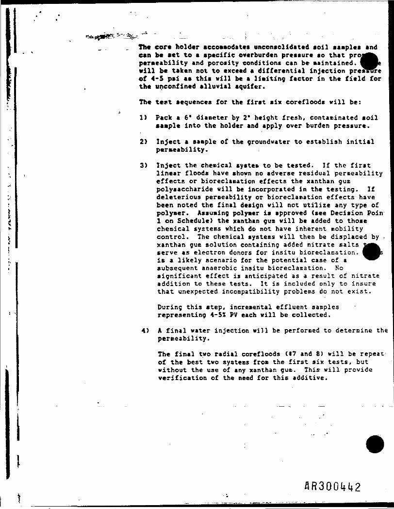
The core holder accommodates unconselidated soil samples andcan be set to a specific overburden pressure so that projpermeability and porosity conditions can be maintained.vill b« taken not to exceed a differential injection preslof 4-5 psi as this will be a limiting factor in the field forthe unconfined alluvial aquifer.
• viiumeJRre
The test sequences for the first six core floods will be:
1) Pack a 6' diameter by 2' height fresh, contacinated soilsample into the holder and apply over burden pressure.
2> Inject a sample of the groundwater to establish initialpermeability.
3) Inject the chemical system to be tested. If the firstlinear floods have shown no adverse residual permeabilityeffects or bioreclanation effects the xanthan gumpolysaccharide will be incorporated in the testing. Ifdeleterious permeability or bioreclanation effects havebeen noted the final design will not utilize any type of
I polymer. Assuming polymer is approved (see Decision Poinj 1 on Schedule) the xanthan gum will be added to those
chemical systems which do not have inherent nobilitycontrol. The chemical systems will then be displaced by .xanthan gum solution containing added nitrate saltsserve as electron donors for insitu bioreclacstion.is a likely scenario for the potential case of asubsequent anaerobic insitu bioreclacation. Nosignificant effect is anticipated as a result of nitrateaddition to these tests. It is included only to insurethat unexpected incompatibility problems do not exist.
During this step, incremental effluent samplesrepresenting 4-5X PV each will be collected.
4) A final water injection will be performed to determine thepermeability.
The final two radial corefloods (17 and 8) will be repeatof the best two systems from the first six tests, butwithout the use of any xanthan gum. This- will provideverification of the need for this additive.
flR300H2
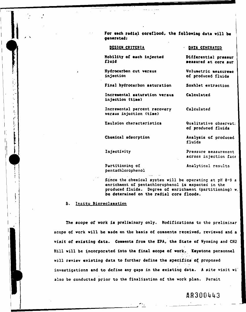
For each radial coreflood, the following data will begenerated:
DES1CM CRITERIA DATA GENERATED
Mobility of each injected Differential pressurfluid measured at core sur
Hydrocarbon cut versus Volumetric measuremeinjection of produced fluids
Final hydrocarbon saturation Soxhlet extraction
Incremental saturation versus Calculatedinjection (time)
Incremental percent recovery Calculatedversus injection (time)
Emulsion characteristics Qualitative observat;of produced fluids
Chemical adsorption Analysis of producedfluids
Injectivity Pressure measurementacross injection face
Partitioning of Analytical resultspentachlorophenol
Since the chemical system will be operating at pK 8-9 aenrichment of pentachlorophenol is expected in theproduced fluids. Degree of enrichment (partitioning) w.be determined on the radial core floods.
B. Insitu Bioreelaaation
The scope of work is preliminary only. Modifications to the preliminar
scope of work vill be made on the basis of comments received, reviewed and s
visit of existing data. Comments from the EPA, the State of Wyoming and CK2
Kill will be incorporated into the final scope of work. Keystone personnel
will review existing data to further define the specifics of proposed
investigations and to define any gaps in the existing data. A site visit vi
also be conducted prior to the finalization of the work plan. Permit
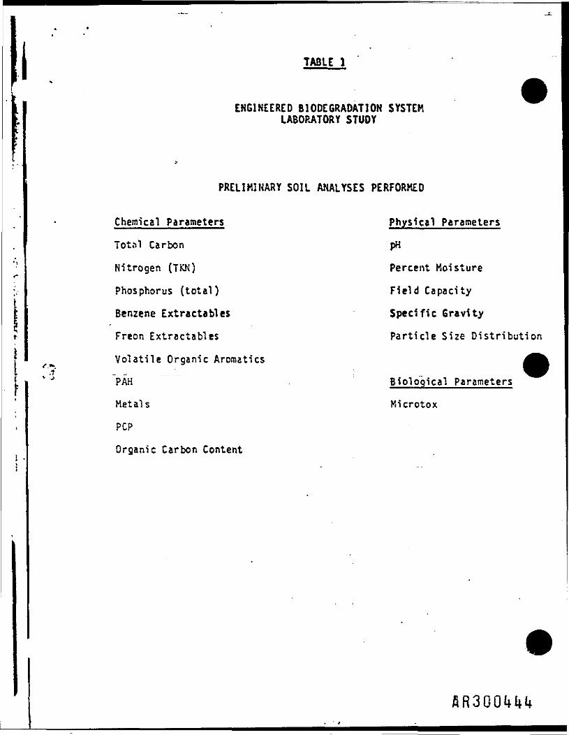
TABLE 1
ENGINEERED BIODEGRADATION SYSTEMLABORATORY STUDY
PRELIMINARY SOIL ANALYSES PERFORMED
Chemical Parameters Physical Parameters
Total Carbon pH
Nitrogen (TKK) Percent Moisture
Phosphorus (total) Field Capacity
Benzene Extractives Specific Gravity
Freon Extractables Particle Size Distribution
Volatile Organic Anomalies
PAH Biological Parameters
Metals Microtox
PCP
Organic Carbon Content
flR300UUl»
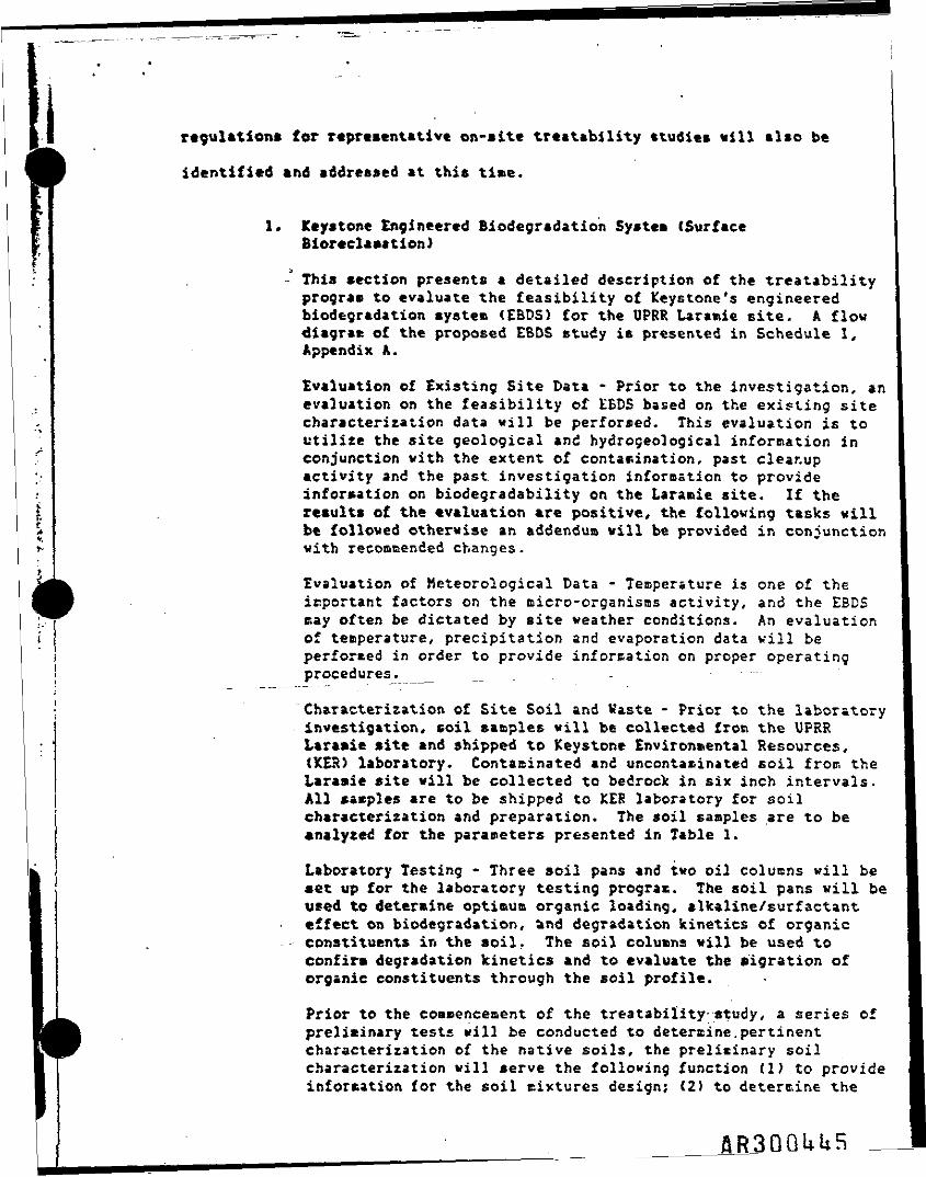
regulations for representative on-site treatability studies will also be
identified and addressed at this time.
1. Keystone Engineered Biodegradation System (SurfaceBioreclamation)
This section presents a detailed description of the treatabilityprogram to evaluate the feasibility of keystone's engineeredbiodegradation system (EBDS) for the UPRR Laramie site. A flowdiagram of the proposed EBDS study is presented in Schedule I,Appendix A.
Evaluation of Existing Site Data - Prior to the investigation, anevaluation on the feasibility of £BDS based on the existing sitecharacterisation data will be performed. This evaluation is toutilize the site geological and hydrogeological information inconjunction with the extent of contamination, past cleanupactivity and the past investigation information to provideinformation on biodegradability on the La r a tie site. If theresults of the evaluation are positive, the following tasks willbe followed otherwise an addendum will be provided in conjunctionwith recommended changes.
Evaluation of Meteorological Data - Temperature is one of theimportant factors on the micro-organisms activity, and the EBDSstay often be dictated by site weather conditions. An evaluationof teaperature, precipitation and evaporation data will beperformed in order to provide information on proper operatingprocedures. _ __ _
Characterization of Site Soil and Waste - Prior to the laboratoryinvestigation* coil samples will be collected froti the UPRRitramie site and shipped to Keystone Environmental Resources,<K£R) laboratory. Contaainated and uncontaninated soil frocs thetaraaie site will be collected to bedrock in six inch intervals.All samples are to be shipped to KER laboratory for soilcharacterization and preparation. The soil samples are to beanalyzed for the parameters presented in Table 1.
Laboratory Testing - Three soil pans and two oil colucns will beset up for the laboratory testing program. The soil pans will beused to determine optimum organic loading, alkaline/surfactanteffect on biodegradation, and degradation kinetics of organicconstituents in the soil. The soil columns will be used toconfirm degradation kinetics and to evaluate the migration oforganic constituents through the soil profile.
Prior to the commencement of the treatability study, a series ofpreliminary tests will be conducted to determine.pertinentcharacterization of the native soils, the preliminary soilcharacterization will serve the following function (1) to provideinformation for the soil cixtures design; <2) to determine the
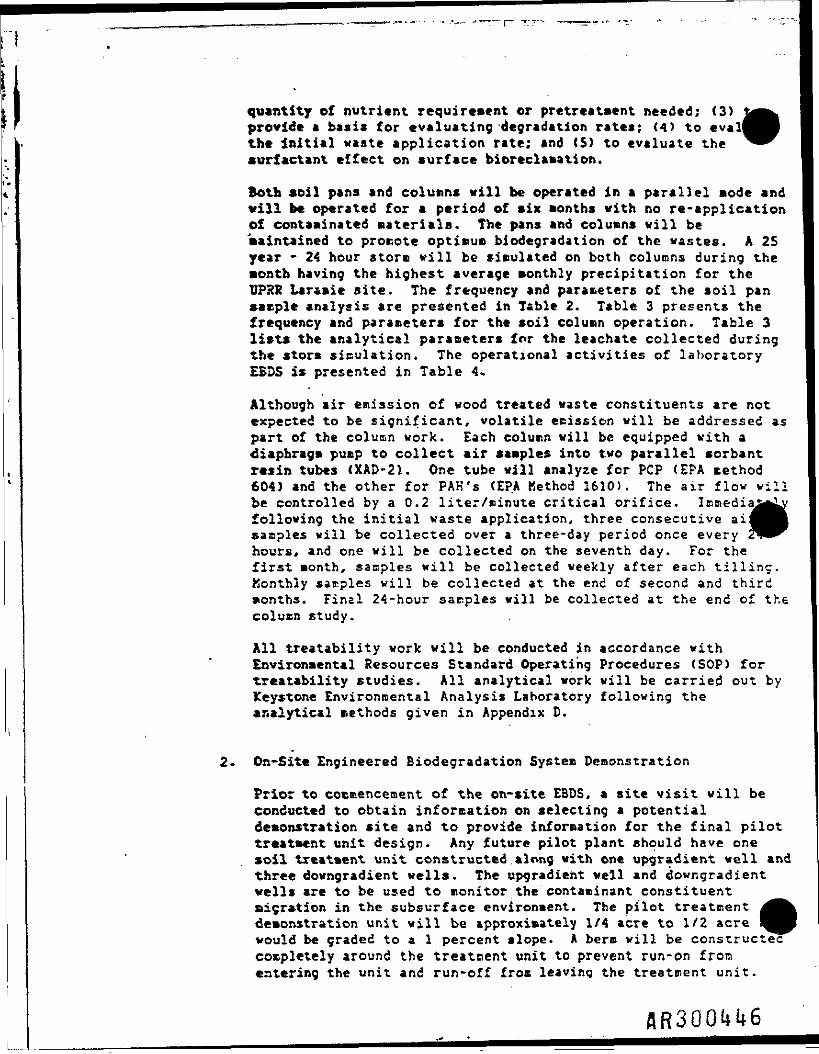
quantity of nutrient requirement or pretreatment needed; (3)provide a basis for evaluating degradation rates; <4) to evalthe initial waste application rate; and (5) to evaluate thesurfactant effect on surface bioreclamation.
Both soil pans and columns will be operated in a parallel mode andvill be operated for a period of six months with no re-applicationof contaminated materials. The pans and columns will bemaintained to promote optinun biodegradation of the wastes. A 25year - 24 hour storm will be simulated on both columns during the•ontb having the highest average monthly precipitation for theUPRR Lar&mie site. The frequency and parameters of the soil pansacple analysis are presented in Table 2. Table 3 presents thefrequency and parameters for the soil column operation. Table 3lists the analytical parameters for the leachate collected duringthe storm simulation. The operational activities of laboratoryEBDS is presented in Table 4*
Although air emission of wood treated waste constituents are notexpected to be significant, volatile scission will be addressed aspart of the column work. Each column will be equipped with aDiaphragm pump to collect air samples into two parallel sorbantresin tubes (XAD-21. One tube will analyze for PCP (EPA sethod604) and the other for PAK's (EPA Kethod 1610). The air flow villbe controlled by a 0.2 liter/minute critical orifice. Immedia^following the initial waste application, three consecutive ai:samples will be collected over a three-day period once everyhours, and one will be collected on the seventh day. For thefirst month, samples will be collected weekly after each tilling.Konthly samples will be collected at the end of second and thirdmonths. Final 24-hour sarples will be collected at the end of thecolumn study.
All treatability work will be conducted in accordance withEnvironmental Resources Standard Operating Procedures (SOP) fortreatability studies. All analytical work will be carried out byKeystone Environmental Analysis Laboratory following theanalytical methods given in Appendix D.
2. Or.-Sit* Engineered Biodegradation System Demonstration
Prior to commencement of the on-site EBDS, a site visit will beconducted to obtain information on selecting a potentialdemonstration site and to provide information for the final pilottreatment unit design. Any future pilot plant should have onesoil treatment unit constructed along with one upgradient well andthree downgradient wells. The upgradient well and downgradientwells are to be used to monitor the contaminant constituent&igr»tion in the subsurface environment. The pilot treatmentdemonstration unit will be approximately 1/4 acre to 1/2 acrewould be graded to a 1 percent slope. A bero will be constructed"completely around the treatment unit to prevent run-on fromentering the unit and run-off from leaving the treatment unit.
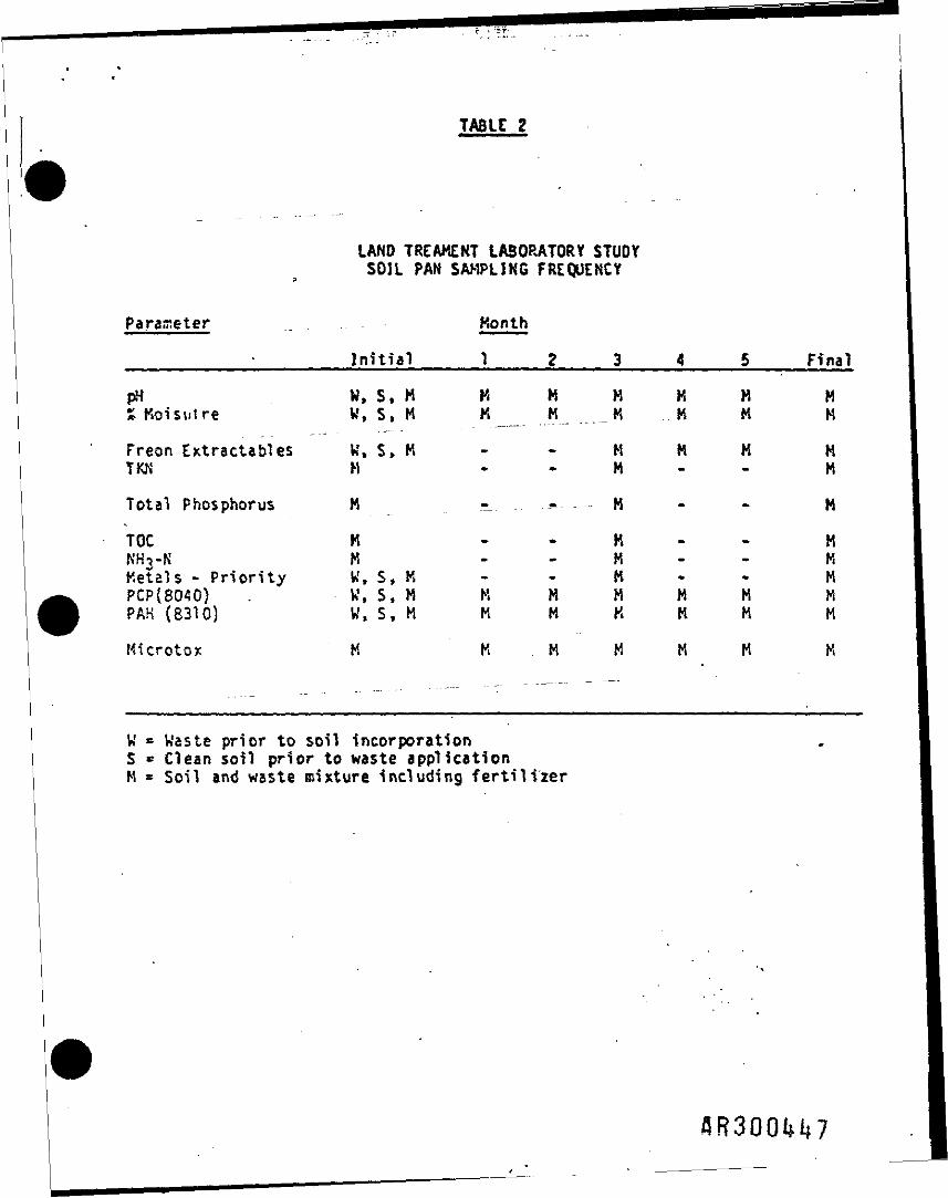
TABLE 2
LAND TREAMENT LABORATORY STUDYSOIL PAN SAMPLING FREQUENCY
Parameter _ Month
______Initial____1 g 3 4 5 Final
pH W, S, M K M H M M MSKoisulre W, S. « K « _K K M M
Freon Extractables W, S, M - - M M M MTKN H M - - M
Total Phosphorus M n « H - - M
TOC M H - - MKH3-K M K - - HKetals - Priority W, S, K - - H - - MPCP(8Q40) . W, S, M K M « M M HPAK (8310) W f S , M M M K M H H
Kicrotox M K M H M M K
S » nLn Lf *? S011 in«rporation2 pnor to wast€ application
and waste mixture including fertil i»r
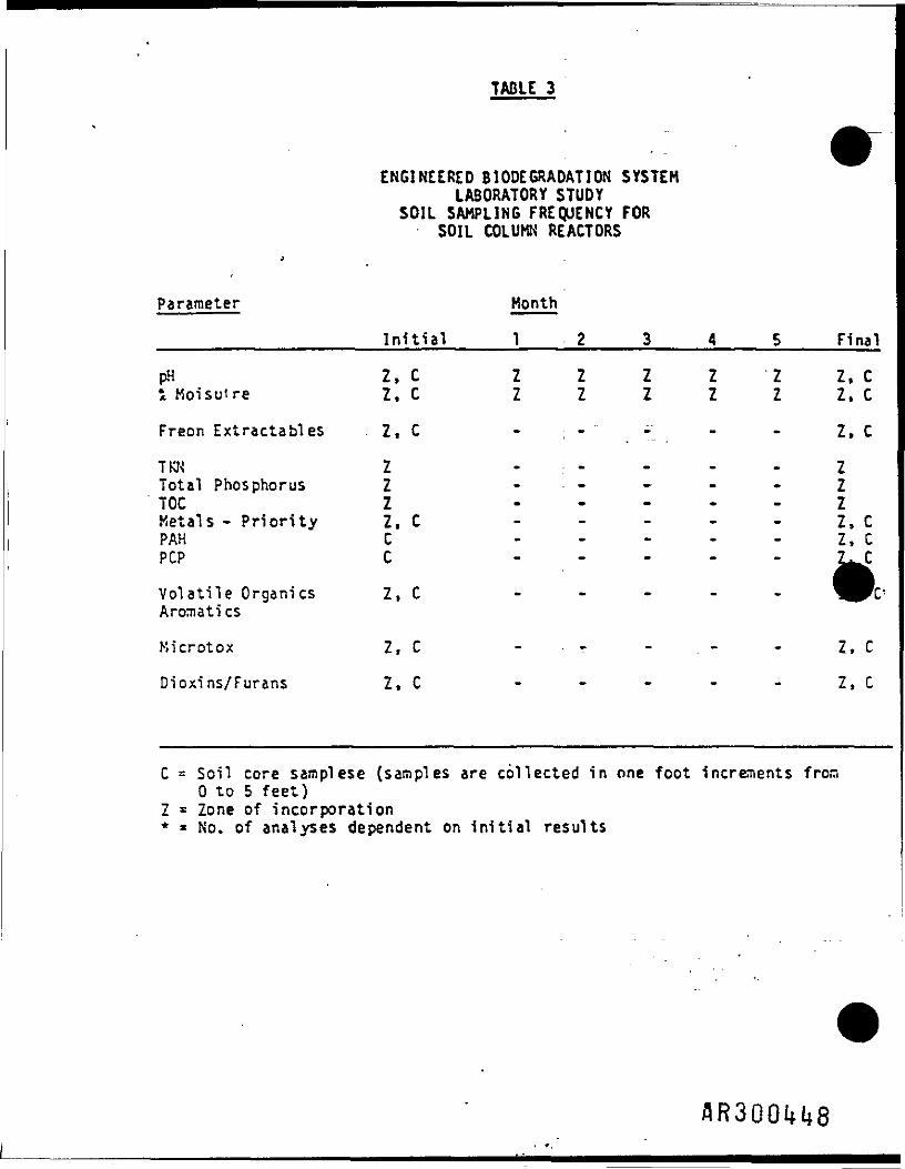
TABLE 3
ENGINEERED BIODEGRADATION SYSTEMLABORATORY STUDY
SOIL SAMPLING FREQUENCY FORSOIL COLUMN REACTORS
Parameter Month
_________________Initial_____12 3 4 5 Final
pH Z, C Z Z Z Z Z Z, Ci Koisuire Z, C Z Z Z Z Z Z. C
Freon Extractables Z, C - ; - " - - - Z, C
TKK Z - : - - - - ZTotal Phosphorus Z . . . . . . 2TOC Z . . . . . 2Metals - Priority Z, C - - - - - Z, CP A H C - - - - - Z , CPOP C . . . . . £^c
Volatile Organics Z, C . . . . .Aromati cs
Kicrotox Z, C -- - - - Z, C
Dioxins/Furans Z, C - - - - - Z»C
C = Soil core samplese (samples are collected in one foot increments from0 to 5 feet)
Z » Zone of incorporation* * No. of analyses dependent on initial results
flR3QOH8

TABLE 4
OPERATIONAL ACTIVITIES OF LABORATORYENGINEERED BIODEGRADATION SYSTEM STUDY
Activity Frequency
Ambient Air Temperature D«^y *
Tilling • Weekly
Relative Humidity Daily *
Soil Moisture Weekly
Soil pH Weekly
Watering As Necessary
Lime Addition As Necessary
Manure i Fertilizer Addition As Necessary
Analytical Sampling Monthly
i Not including Saturday and Sunday
8R300H9
Run-off vill fee collected at the low slope position of thetreatment unit and diverted into a storm retention collectionarea. A water collection device will be installed in order todetermine the extent of contaninant migration from the treatmenttone.
Prior to the loading of contaminated soil to the EBDSdemonstration plot, background soil water and air quality will betaken. The list of parameters to be analyzed for is presented inTable 6. Vater quality samples will be taken from the upgradientand downgradient wells. Background soil samples will be takenfrom the upper soil layer in the proposed treatment area. Airquality sampling will also be perforated upwind and downwind of theproposed treatment area.
The monitoring devices would be installed and storm watercollection area constructed prior to the loading of contaminatedsoil.
The operational activities required after a pilot plant start-upinclude watering, soil pH adjustment, nutrient adjustment, anddata recording. Tables S and 6 present the environmentalmonitoring plan for the treatment demonstration plot. Monitoringat the site would consist of soil sampling, soil pore watersampling, upgradient and downgradient groundvater saicpling and airsampling. The purpose of the soil and soil pore water samplingwill be to assess the performance of the treatment demonstrationplot with respect to the degradation, immobilization, andtransforuation of the applied waste constituents. The purpose ofgroundwater and air sampling will be to evaluate the effects ofthe soil treatment process on the site environmental quality.
The ou-site treatment demonstration activities will be performedby the UPRR Laraaie personnel trained by Keystone with exceptionof the initial start-up, initial midperiod and final sampling.
3. Subsurface Bioreclamation.
The primary objective of the treatability program will be toestablish the technical feasibility of this integrated technologyutilizing insitu soil wash and subsurface bioreclamation and toidentify the most cost-effective remedial action procedure. Theproposed project task breakdown and schedule for the .subsurfacebioreclamation is presented in Schedule I, Appendix A. After thefinal scope of work is approved, the treatability program iscomposed of nine subtasks to be performed.
a. Pretreatoent Evaluation of Representative Pumped Groundwater -The pretreatuent evaluation will investigate the\water qualityof the pumped groundwater after primary oil recovery andadditional oil/water separation if necessary. Waterscontaining any combination of free or emulsified oil, excesssuspended solids and/or high iron content will require
flR300l»50
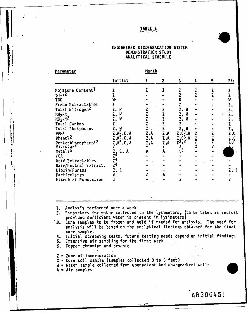
TABLE 5
ENGINEERED BIODEGRADATION SYSTEMDEMONSTRATION STUDYANALYTICAL SCHEDULE
Parameter Month
_ _ _ _ _ _ _ _ _ _ _ _ _ _ _ _ I n i t i a l _ _ _ _ _ 1 2 3 4 5 Fir
Moisture Content1 Z Z Z Z Z Z 2pH^-2 Z Z Z Z ZTOC W- W - - WFreon Extractables Z . - Z - Z»Total Nitrogen? Z, H Z Z Z. W - - Z,NH3-K Z, W Z Z Z, W - Z,HtyN2 z, w 2 z z, y - - z»Total Carbon Z Z Z Z - - ZTotal Phosphorus Z, W Z Z 2, V - - Z,PAH2 Z.A5 C,W Z»A Z,A Z,C3,W Z Z Z,CPhenol 2 Z,A5,C,W Z,A Z,A Z,C3,W Z 7 Z,CPentachl orophenol2 z »A5.C,W Z ,A Z,A C3»w * 2 2»CHicrotox2 Z - Z Z 2 ZMetals6 2, C, A A A C3 -VGA Z4 . . . . .
, Acid Extractables Z4 - - ^ - . -•i Base/Neutral Extract. Z 4 . - . . . . -M Dioxin/Furans Z, C - : » - - - Z»C
I Parti culates A A A - - -Kicrobial Population 2 - . - Z - •? Z
1. Analysis performed once a week2. Parameters for water collected in the lysimeters, (to be taken as indicat
provided sufficient water is present in lysimeters)3. Core samples to be frozen and held if needed for analysis. The need for
analysis will be based on the analytical findings obtained for the finalcore sample.
4. Initial screening tests, future testing needs depend on initial findings5. Intensive air sampling for the first week6* Copper chromium and arsenic
2 * Zone of incorporation , • •.. •C * Core soil sample (samples collected 0 to 5 feet)W * Water sample collected from upgradient and downgradient wellsA * Air samples
flR30Qlf5

TABLE 6
ENGINEERED BIODEGRADATION SYSTEM DEMONSTRATION STUDYBACKGROUND CONDITION MONITORING PARAMETERS
Parameters^) Water Soil Air
pH .... _ X X
Organic Carbon Content X
TOC X
Total Nitrogen X X
Total Phosphorus X X
NK3-N X X
N03-N X X
PAH (EPA 610) X X X
Pentachlorophenol X X X
Phenolics X X X
Kicrotox X X
Metalstb) X 'X X
Particulates X
Heating Value (BTU) X
Ash Content X
(a) Analytical methods presented in Appendix A*
(b} Metals include copper, chromium and arsenic.
flR3QO!*52
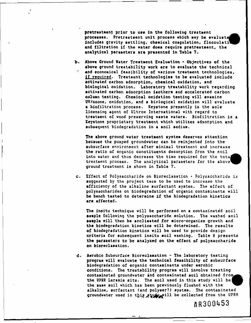
pretreatmenj prior to use in the following treatmentprocesses. Pretreatnent unit process which may be evaluatincludes gravity settling, chemical coagulation, flocculati'and filtration if the water does require pretreatment, theanalytical parameters are presented in Table 7.
b. Above Ground Water Treatment Evaluation - Objectives of theabove ground treatability work are to evaluate the technical
J and economical feasibility of virious treatment technologies,fr£ required. Treatment technologies to be evaluated includeactivated carbon adsorption, chemical oxidation, andbiological oxidation. Laboratory treatability work regardingactivated carbon adsorption isotherm and accelerated carboncolumn testing. Chemical oxidation testing vill examineUV/ozone, oxidation, and a biological oxidation vill evaluatea biofiltration process. Keystone presently is the solelicensing agent of Ultrox International vith regard totreatment of wood preserving waste waters. Biofiltration is aKeystone proprietary treatment which utilizes adsorption andsubsequent biodegradation in a soil medium.
The above ground water treatment system deserves attentionbecause the pumped groundvater can be reinjected into thesubsurface environment after minimal treatment and increasethe ratio of organic constituents desorption from the soilinto water and thus decrease the time required for the totatreatment process. The analytical parameters for the aboveground treatment is shown in Table 7.
c. Effect of Polysaccharide on Bioreclamation - Polysaccharide issuggested by the project team to be used to increase theefficiency of the alkaline surfactant systea. The effect ofpolysaccharides on biodegradation of organic contaminants willbe bench tested to determine if the biodegradation kineticsare affected.
The insitu technique will be performed on a contaminated soil•ample following the polysaccharide solution. The washed soilsample vill then be acclimated for micro-organism growth andthe biodegradation kinetics will be determined. The resultsof biodegradation kinetics vill be used to provide designcriteria for subsequent insitu soil washing. Table 8 presentsthe parameters to be analyzed on the effect of polysaccharideon bioreclamation.
d. Aerobic Subsurface Bioreclamation - The laboratory testingprogram will evaluate the technical feasibility of subsurfacebiodegradation of organic contaminants under aerobicconditions. The treatability program will involve treatingcontaminated groundvater and contaminated soil obtained frothe UPRR Laramie site. The soil used in this study vill bethe sa»e soil which has been previously flushed vith thealkaline, surfactant (and polymer?) system. The contacinatedcroundwater used in thig .-gVffiff l be collected from the UPRR
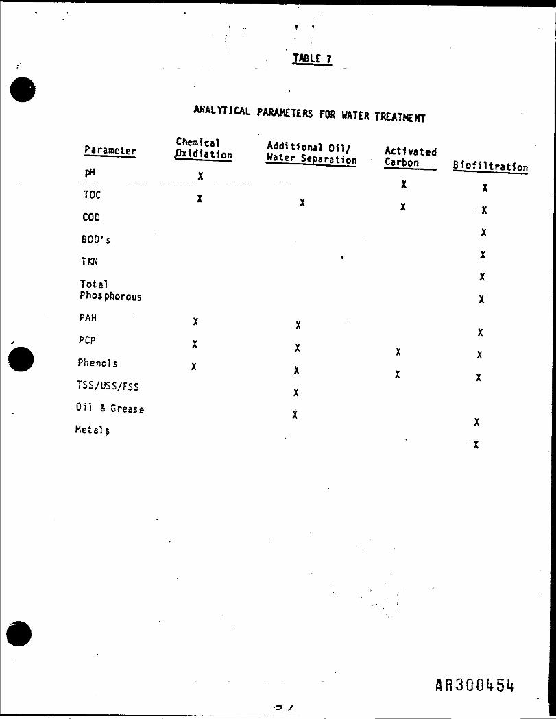
TASlt 7
ANALYTICAL PARAMETERS FOR WATER TREATMENT
Chemical
pn x ————x X
TOC X vx x xCOD
BOD's X
TKN ' X
Total XPhosphorous X"» i ,pcpPhenols v
X vTSS/USS/FSS x
Oil S Grease x
Metals X

taramie cite. Reactors are to be operated under aerobicconditions vith a supplemental oxygen source of induced oor hydrogen peroxide. After pretreatment of contaminatedby soil washing, the water is then passed through the reactorvith addition of nutrients and oxygen sources to create andmaintain a biological active environment. Loss ofpermeability will be evaluated for both induced oxygen andhydrogen peroxide.
Once the system is operating, the water will be sampled andanalyzed for pH, DO and KH. to determine additional nutrientor oxygen source requirements. The pH of the water used inthis study is to be maintained within a range of 7 and 8. Itit anticipated that the reactor will be operated for a periodof four months. The analytical paraaeters and samplingfrequency are presented in Table 9.
Anaerobic Subsurface Bioreclamation - Bench scale biologicaltreatability testing will be conducted to evaluate theperformance of anaerobic microbial degradation for subsurfacebioreclamation. The soil used in this study is to be obtainedfrom the UPRR Laramie site and followed by insitu washingprocess. The contaminated water used in this process will beobtained froa the Laranie and/or followed by pretreatment.After insitu soil washing, the soil will be placed in areactor vith contaminated groundwater flow through thereactor. The reactor vill be operated under anaerobicconditions (absence of oxygen) with nitrate added to serve asthe electron acceptor.
The water through the anaerobic reactor will be sampledperiodically during the operation to insure the reactormaintains an anaerobic condition and a suitable environmentfor microbial degradation to occur. During the operation, thenutrient and electron acceptor source will be maintained at alevel to insure that it does not becooe a limiting factor.The pH of the reactor will be maintained in a range of 7 and8. The reactor is to be operated for a period of fourmonths. Table 9 shows the analytical parameter and samplingfrequency of the study.
After completion of all bench testing an interim report willbe prepared and submitted to the client prior to initiatingany field work. The report will discuss results to date andthe estimated costs and effectiveness for both the pilot unitand a full field expansion.
Integrated Insitu Soil Washing and Subsurface BioreclamationThe project team will evaluate various treatment alternativesto determine the most technical feasible and cost effectivetreatment alternative involving pretreatoent, abovegroundwater treatment, aerobic and anaerobic subsurfacebioreclamation, and insitu soil washing. The evaluation ofthese treatment alternatives vill involve addressing both
AR300l*55

TABLE 8
TOCTm
ANALYTICAL PARAMETERS FOR EFFECT OFPOLYSACCHARIDE ON BI ORE CL ACTION
parameter r—————— Frequency
Total Phosphorous ,,,-'•• ::; -•— ; " r_i' ••" ' . - - . . . • „ . • - - . . ._."•*"
Pol^accharide u= - - .- ..---. . .-- ^ ,- -=. . - . .=- n
PAH
W = weekly2W * biweeklyK = monthly
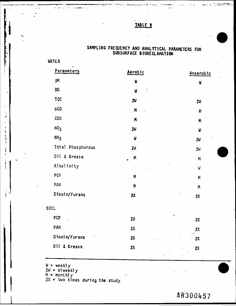
TABLE 9
SAMPLING FREQUENCY AND ANALYTICAL PARAMETERS FORSUBSURFACE BIORECLAMATION
WATER>
Parameters Aerobic Anaerobic
pH V V
00 W
TOC 2U 2W
liOD M . H
COD M M
NOs 2W W
NH3 W 2W
Total Phosphorous 2W 2W
Oil & Grease M H
Alkalinity . W
POP K H
PAH K H
Dioxin/Furans 2X 2X
SOIL :
PCP 2X 2X
PAH 2X 2X
Dioxin/Furans ' 2X 2X
Oil I Grease 2X 2X
W * weekly2W * biweeklyH « mont hi y2X * two times during the study
federal and state regulations with handling of pumpedcontaminated groundwater, recovered oil products andcontaminated soil. For this task, guidance from both EPA andthe State of Wyoming is needed so that the proper permittingregulations and processes can be addressed.
If delay* are experienced in obtaining the necessary permits,the time for completion of the related tasks <on~site
- integrated treatment systems demonstration) will be delayed.
h. Pilot Unit Design Construction and Operation - The informationobtained from the bench scale testing will be integrated intothe final on-site pilot unit design. It is envisioned thatthe process vill consist of insitu soil washing, subsurfacebioreclamation, oil product recovery, contaminated waterpretreatment and above ground water treatment system. Theinformation obtained from the treatment unit processes willalso be utilized for recommendation of on-site operationprocedures.
It is planned that the on-site pilot unit will begin operatingon Way 25, 1987 subject to the local weather condition. It isanticipated that the pilot unit will be operated for a periodof six months with periodical eacspling and analysis. Thesampling frequency and analytical parameters will bedeternined after reviewing the laboratory unit processresults. Operation of the pilot unit will be handled by theproject team.
i. Report Preparation - At the conclusion of the on-sitetreatment evaluation, a final report will be prepared. Thisreport vill include:
1) £ review of procedures and results of all the treatmentunit processes performed;
2) An engineering evaluation of treatment alternatives';
3) Identification of the most technically feasible treatmentalternatives;
4} Recommendation of design criteria and operationalprocedures for a full scale treatment system.
The results of the treatability work vill include adescription of the procedures used and the analyticalresults obtained. Engineering evaluation of the differenttreatment unit processes (soil washing, oil recovery,groundvater pretreatment, above ground water treatment andinsitu bioreclamation) pertains to estimation of both
AR30Ql*58

treatment level and capital and 0 < H costs associated,with each process so that the moat technically feasib?
* and cost effective full scale system can be recommence!Projected cleanup level of the recommended treatmentsystem vill also be provided. The engineering evaluationof the treatment process will be based upon therepresentative groundvater and soil obtained from the UPERLaramie site.j
C. INJECTION SYSTEM EVALUATION AND DESIGN
CH2K Hills Figures 3-7 Phase XI Report on the Laramie site shows the
unconfined alluvial thickness is generally less than 14 feet thick. An
insertion system vill be designed addressing the following problem areas:
(1) extreme shallow depth;C2> potential leakage of injected fluids up around the well casing or
trench pipe;(3) nature of completion e.g. cementing, grouting;(4) method of emplacement£5) maximum distance between infection and producing wells(6) coirpleted intervals(7) bedrock topography(8) parameters as determined by the insitu soil wash and insitu
bioreclacation studies;(9) cost.
Design will initially be conceptually. If the decision is made to proceed
with a pilot plant design, then limited field testing of a trench and veil
point system vill be conducted on site. This field data vill be incorporated
into the pilot plant design and construction.
flR3QQl*59
i * *
f
IV. ADK3NJSTRAT10N/ORCANIZATIOK
All administrative functions vill be performed at MTARRI'a home office
located at 1511 Washington Avenue, Golden, Colorado, 80401. HTARRI's remedia
action trained personnel vill collect the samples and insure USDS and chain o
custody sheets are maintained.
A. OA/OC and Safety
Dr. Stan Rickard, a registered professional engineer, will review the
project and insure the OA/OC on sample representativeness and bench scale/pile
plant design meet acceptable limits. Keystone's QA/QC program (see Appendix !a*'* will be the lead docuaent to be incorporated and followed by the entire KTARR]
teas.
OC will be maintained by documentation of field and laboratory notebooks
combined with the recommended sampling techniques as outlined in the Phase II
CH2M Kill report on the UPRR site. However, if acceptable by the client,
KTARRI would recommend the use of screening analytical techniques while
developing bench scale chemical and biological systems. These screening
systems will be:
1) Soxhlet extraction of the sands with dichloromethane followed by
evaporation of the dichloromethane and weighing of the residual oil.
Residual oil weights are compared to weight loss for the extracted sample.
This system has a detection limit of 0.01 grams and has proven reliable
when compared to EPA certified lab analyses. flR3QOU60
•- r
2) IR scan utilizing a Perkin Elmer instrument.
After the chemical/biological system is developed a certified analysis i
utilized to determine the exact concentrations of the various fractions and tj
obtain partition coefficients.
KTARRI's corporate remedial action safety program is entitled 'Excellence
for the Eighties". The program is implemented and maintained by the Corporate
Safety Coordinator, in accordance vith the Corporate Safety Manual, federal,
state, and local rules and regulations. The Corporate Safety Coordinator
oversees project safety programs through regular visits to the project labs and
_ job sites and through periodic safety reviews vith the lab and field perso ul.
HTAR8I has a published coeprehensive safety program for remedial action
cleanups. A copy of this program would be provided under separate cover.
The Keystone environmental analytical laboratories is currently being
qualified to conduct and support Superfund site quality assurance programs for/'
phenols, acid/base/neutral aromatics, pentachlorophenols and aliphatic/aromatic
oils. For chlorinated dibenzodioxins and dibenzofurans. California Analytical
Laboratories *tCAt) in Sacraoento will be utilized. CAL labs are certified and
licensed to handle dioxin Materials.

B. Project Management/Organization
MTARRI, as prime contractor, will be responsible for the entire projectj
administration, execution and reporting. Dr. Paul B. Trost will be the projec
leader for KTARRI and vill have overall project Management authority.
Subcontractors vill be directed as shown in the organization chart with a
single line of communication to CH2M Kill. However, additional lines of
coordination are established between the individual subcontractors to expedite
data exchange and coordination. Work plans from the subcontractors will be
approved by Dr. Trost prior to submission for approval by CH2K Hill.
C. Reporting
Monthly activity reports will be submitted to CH2K Hill describing the
status of all current activities and the next months work plans. In addition,
these reports vill specify the percentage completion of each task and will
locate the current activity on the schedule herein submitted.
Contract hours will be broken down to the quarter hour. Copies of all
third party invoices and analytical results/costs vill be provided to CH2K
Hill.

•
(••
r
«fc»f-»tf
•
, • v
•»
E
D
•
,
cc
J
2 -g*0|is1
£jU 4JOJtrt
CJ
£10o.
1Vor «^£S~= 1s. ot) UW
«.4)
•*-»
°
«£»-•o.*1_o
eo*jU
•o o
• U< 3to*1- •Q X
V H
•
I2'3t
p o
'14-> _CJ
Admi
nist
rati
on"CT TrTpTelt"
•«
—
"& 'C (** cftl *»(»*Q.e Eh-
UJ O .K
2 'S•r- ftj| .u-z(=:
c*0|
Etci20 V
t. -o ->Op3 « -
Clt. U— O Q
1
•=1in
ji r—3(t- —*J 3 «•|on caVI
£jr'
3U-
*
t.o
4-1
CL*
•t.O
••1
r1°'
1'7,1a,01
a>CJ(J=
i-l3 •
situ
Blo
recl
arna
tion
TlcShea
"*»"*
•
UIcs •- •
O Q
o - B£ 5 mW< o-*— • to
CJ aso r>
•
•flR300i*63

MTARRI
UPRR CREOSOTE REMOVAL
BY SOU WASHING AND PRELIMINARY
PROPOSAL FOR SUBSEQUENT EVALUATIONS
KTA Remedial Resources* Inc.1511 Washington Ave.Golden, CO 80401{303} 279-4255

——————————————————— MTARRI ————————————————IKTRODUCTIOH
HTA Remedial Resources* Inc. (MTARRI) has developed proprietary state-of-the-art volute reduction techniques for treating certain hazardous wastes*These techniques have been developed utilizing technology transfers from boththe mining and oil business to achieve cost effective cleanups. The technologyborrowed fro* the mining business Is proven and, 1n fact, 1s currently used totreat over 100 million tons of ore grade rock/year; similarly, the oil tech-nology Is over 20 years old and has been economically applied to "wash" addi-tional oil from reservoirs.
jA general description of this state-of-the-art process 1s Included In
Appendix A of the proposal. Succinctly, the heart of the technique utilizesfroth flotation combined with EPA-approved surfactants and other chemicals toa) free the creosote from the soil particles and; b) concentrate and collect thecreosote in the froth. Cleaned (washed) soils are then recycled back to theiroriginal site.
To date HTARRI has conducted over 10 bench scale tests on creosote/penta-chlorophenol/Cu/As/Cr contaminated soils. These soils were obtained from twodifferent sites and have been successfully treated for creosote removal.
Accordingly, MTARRI has drafted this preliminary proposal for UPRR. Pleasebe advised that the time/costs for each phase are approximate. Furthermore,within each phase numerous other decision points should be Incorporated toalways insure the lab and engineering data being generated meets both the EPAand UPRR guidelines.
If this approach is deemed feasible by. all parties, MTARRI would be pleasto prepare a more detailed proposal for approval.
AR30W55

——————————————————— MTARRI ——————————————————UPRR CREOSOTE
SUMMARY
MTA Remedial Resources, Inc., "MTARRI," has proprietary technology ("soilwashing") to cost effectively remove creosote from sands and soils.
Based upon samples obtained from the UPRR Laramie site, MTARRI achieved a99.9+1 removal of the creosote under laboratory conditions utilizing modifiedfroth flotation techniques. The original creosote content was 2.51. Removedcreosote was dispersed in a aqueous phase and recovered. Oil skimming tech-niques common to the oil business can sufficiently remove the creosote and allowthe reclrculation of the bulk of the process water. Projected capitalizationcosts for the "soil washing" equipment based upon 500 tons per day and a 4 yearlife (500,000 tons) would range from $4-6 million; projected operating costsIncluding mining, soil washing and return of clean soil to achieve the creosotesoil/sand separation and water treatment based on MTARRI1s data to date are$40-55/ton.
Thus overall operational and capital amortization costs for the soil/sandto achieve a 99.9+1 creosote removal from 500,000 tons over a 4 year periodwould be $48-67 per ton. Recovered creosote could be returned to UPRR forreuse or sent to a hazardous waste land fill. Salvage value of the processingplant 1s estimated at $l/ton.
MTARRI has also investigated the feasibility of in-situ creosote removaland/or destruction. Two processes are feasible depending on creosoteconcentration. One, MTARRI's APS* system utilizes an alkaline agent and sur-factant to free the creosote from the soils/sands and then a polymer watersystem to displace the viscous freed creosote to a nearby withdrawal well. Asecond system, if the creosote concentration exceeds 1.0%, would be to utilize afire flood technique common to the enhanced oil recovery field. Residualcreosote concentrations for either the APS* system or the fire flood techniquewould be determined in the laboratory, with a goal of less than 101 of the ori-ginal creosote remaining in place.
Projected operating costs would range from $5-20/ton for the APS* and/orthe combustion system. However, under any 1n-situ recovery,system, a signifi-cant amount of organic contaminant, ranging from 4-251 of the origninal con-centration, will remain in the soil. This high residual concentration will bedue to many factors- such as:
1) permeability variations2} differing adsorption methods3) clay adsorption4) flow characteristics of the aquifer5) incomplete combustion
A general process description for both the APS* system and fire flood isgiven in Appendix B.
* Trademark

-——————————————————— MTARRI ———————————————SOIL WASHING
Soil washing will remove the creosote and chlorinated hydrocarbons,allowing their concentration Into 5% or less of the original weight of the cotaminated material. The other 95+1 of the weight, consisting of sands/soils'containing minor amounts of creosote will be returned to the original excavat$1te.
Approximate times and costs are presented for each phase of this Investiga-tion, figure I presents time/manpower chart for a normal schedule and a fasttrack schedule., Please note analytical float may affect certain phases and arethus shown accordingly.
PHASE I Time: 4-6 months ' Cost: $80,000
Objectives: Corapi etc development of flotation section
- determine most cost effective reagants and concentration- determine the distribution of organic and toxic heavy metals bet-ween froth, water and tails
- evaluate necessary physical parameters such as percent solids infeed, feed rate, temperature
- feasibility of recycling recovered creosote- determination of permits and projected time- determine the cost of treatment vs. residual creosote in tails
Decision Point 1: Does detail work of Phase I meet the necessary cleanuprequirements and still appear economically reasonable?If YES, proceed to Phase II; if NO, cease operations.
PHASE II Time: 3-6 months Cost: $40,000
Objectives: Prepare preliminary feasibility report to include
- capital cost- operating cost- salvage cost of processing plant- years of operation
for a 500 ton per day or larger plant.
Decision Point 2: Does feasibility report support operating and capitalizationcosts of $48-67/ton? If YES, proceed to Phase III; if NO,determine most cost sensitive factors and evaluatealternatives.
PHASE III Time: 3-5 months Cost: $180,000
Objectives: Obtain all engineering data necessary for final feasibility studyto include:
* process water recycling and cleanup* final water treatment prior to discharge- most cost effective liquid-solids separation- power and siting requirements- obtain operational permits (NPDES and Wyoming DEQ
permit)
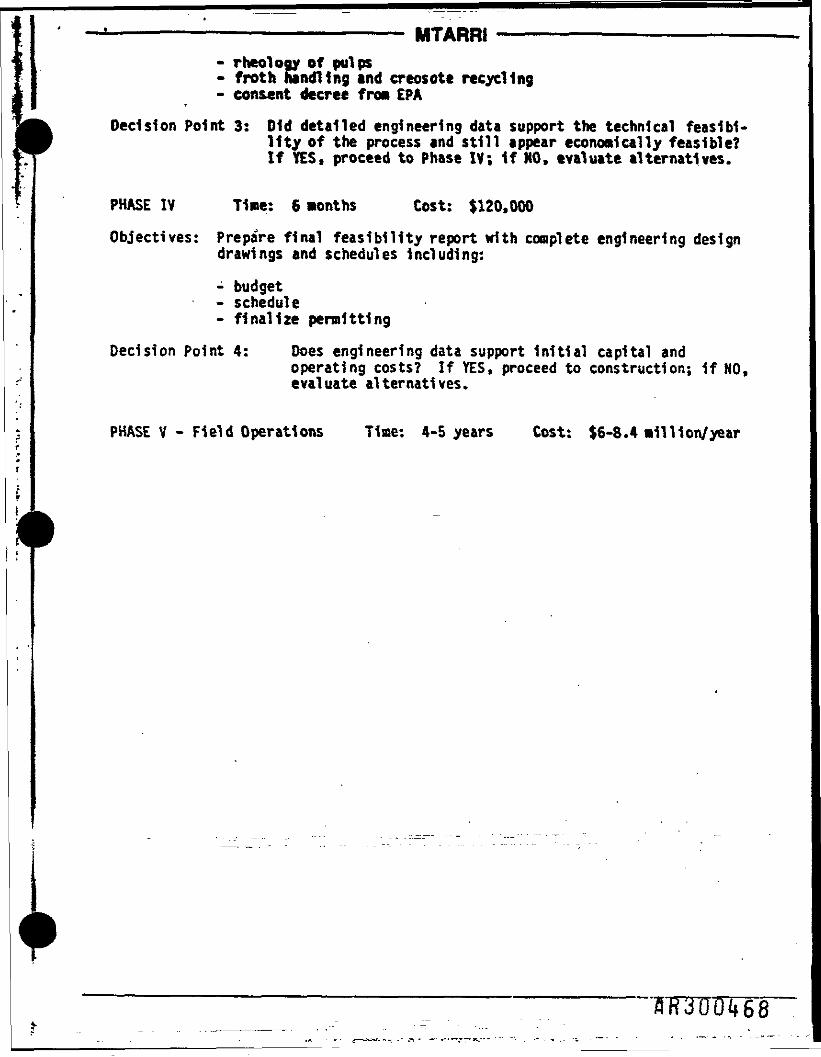
———————————————————— MTARRI —————————————————- r neology of pulps- froth handling and creosote recycling- consent decree from EPA
Decision Point 3: Old detailed engineering data support the technical feasibi-lity of the process and still appear economically feasible?If YES, proceed to Phase IV; If NO, evaluate alternatives.
PHASE IV Time: 6 months Cost: $120,000
Objectives: Prepare final feasibility report with complete engineering designdrawings and schedules including:
- budget- schedule- finalize permitting
Decision Point 4: Does engineering data support Initial capital andoperating costs? If YES, proceed to construction; if NO,evaluate alternatives.
PHASE V - Field Operations Time: 4-5 years Cost: $6-8.4 million/year

* W
r^l•»M
>S" —4*•*« V
O fc*» n- K"•n Crt— r»g a rc»f CL. c
r*
V • •
. -••4 »eo» 5ny 9(B o& **»i. ^n» M
j
~
•oooooooooooCDoo<=>ooooo
»XXXXXXXXXx *.xX BX (O
• X 9XXXXXXXX•MM
*
ro 1o| en
8 Ce xg s§ xXo x«-» xm~ X
• XX
«_ > x^" X8 ' go .X. xO X0 Xo xS° 1_ _ ,
O 1o .4-
O >e.O Xo xroO X3•M. x nX 9I X
X
I X *x_t_ X
XXXfcJX §Xf»X 9XxXXXX*•—111I1
,-L-
ui o <n
?3
ro M
CJ
^
en
m
00
10
-o_,H-•*
I—*CO
1— •**Huttn .
1— >CTt
H-*•xj
1— •CO
VO
rooro>-j
roro
roCU
ro
roen
2?
m
roCO
•&R300l»69
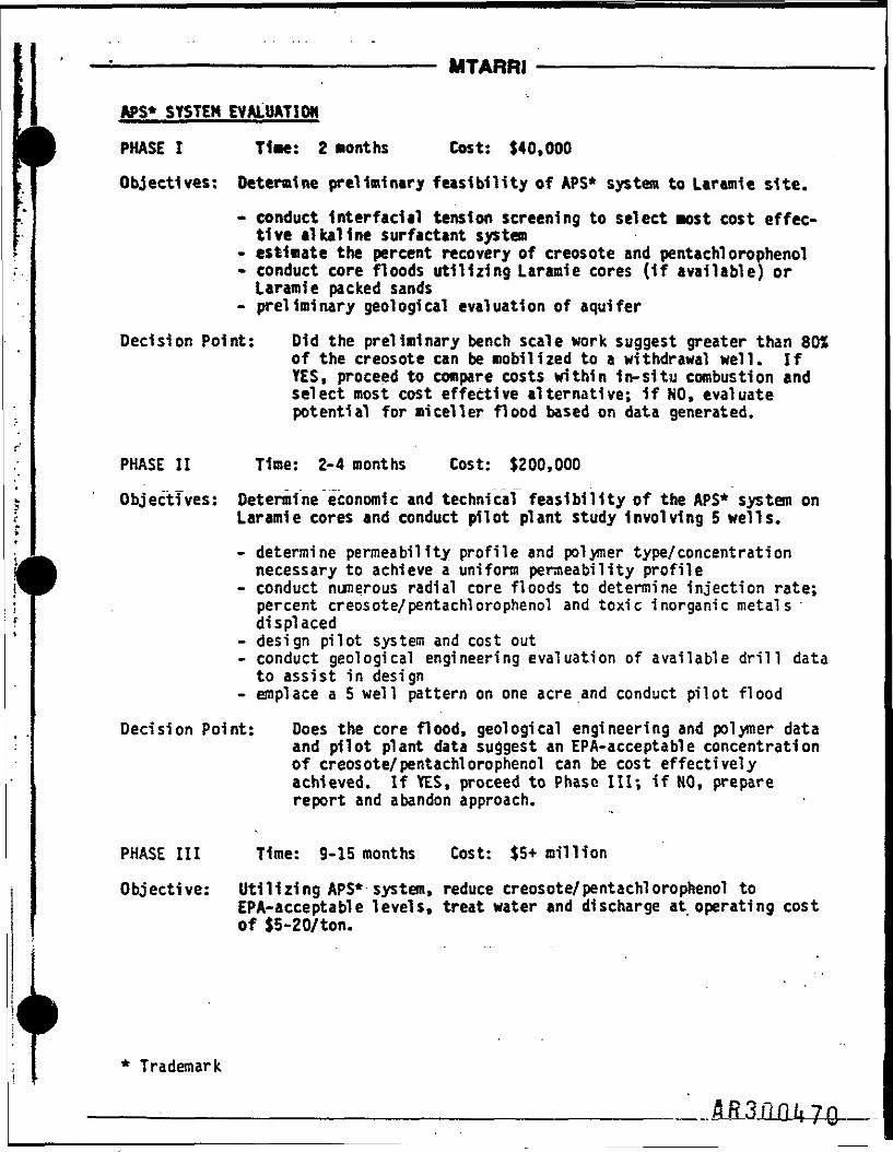
———————————————————— MTARRI —————————————————
APS* SYSTEM EVALUATION
PHASE I Time: 2 months Cost: $40,000
Objectives: Determine preliminary feasibility of APS* system to Laramie site.
* conduct Interfacial tension screening to select most cost effec-tive alkaline surfactant system
- estimate the percent recovery of creosote and pentachlorophenol• conduct core floods utilizing Laramie cores (If available) orLaramie packed sands
- preliminary geological evaluation of aquifer
Decision Point: Did the preliminary bench scale work suggest greater than 80Sof the creosote can be mobilized to a withdrawal well. IfYES, proceed to compare costs within in-situ combustion andselect most cost effective alternative; 1f NO, evaluatepotential for miceller flood based on data generated.
PHASE II Time: 2-4 months Cost: $200,000
Objectives: Determine economic and technical feasibility of the APS* system onLaramie cores and conduct pilot plant study Involving 5 wells.
- determine permeability profile and polymer type/concentrationnecessary to achieve a uniform permeability profile
- conduct nunerous radial core floods to determine injection rate;percent creosote/pentachlorophenol and toxic inorganic metals 'displaced
- design pilot system and cost out- conduct geological engineering evaluation of available drill data
to assist in design- emplace a 5 well pattern on one acre and conduct pilot flood
Decision Point: Does the core flood, geological engineering and polyner dataand pilot plant data suggest an EPA-acceptable concentrationof creosote/pentachlorophenol can be cost effectivelyachieved. If YES, proceed to Phase III; if NO, preparereport and abandon approach.
PHASE III Time: 9-15 months Cost: $5+ million
Objective: Utilizing APS* system, reduce creosote/pentachlorophenol toEPA-acceptable levels, treat water and discharge at operating costof $5-20/ton.
Trademark
_____________________________ ..M.3 n Q It 7 ._,

—————————————————— MTARRI ——————————————
IN-SITU COMBUSTION
PHASE I Time: 1 month Cost: $20,000
Objectives: Determine feasibility of in-situ combustion to achieveEPA-acceptable levels of cleanup- determine if 0.5-2.W creosote can support combustion- determine combustion temperature and compare to destruction tem-perature of pentachlorophenol.
- determine 1f the viscosity of the freed creosote Is sufficientlyreduced to mobilize the creosote to a withdrawal well
* determine depths the technique Is applicable
Decision Point: Is In-situ combustion technically feasible to achieveEPA-acceptable limits? If YES« proceed to compare costs withthe APS* system and select most cost effective alternative.If NO, abandon approach.
PHASE II Time: 1-3 months Cost: $200,000
Note: Objectives, decision points and subsequent costs would be similar tothose previously described in the APS* system.
Trademark
APPENDIX A
DATA PftESEXTED » CONFIDENTIAL AKD PftOPRIETART HUE TO PATENT APPLICATION
General Description of KTARRI's ProprietaryProcess for Detoxification of Soils/Sediments
Contaminated with Hazardous.Organic Materials
Dr. R. Stan RickardHTA REMEDIAL RESOURCES, INC.
1511 Washington Ave.Golden, CO 80401303-279-4255
INTRODUCTION
Currently the cleanup of contaminated soils/sediments 1s accomplished
by excavation, transportation and disposal In an approved hazardous waste
landfill or by Incineration. Costs for these cleanup methods when all
direct and associated costs are considered often exceed $400 per ton. Bothdisposal and incineration have other drawbacks, other than high costs, such
as the lack of approved storage sites, air emissions from incineration "
and the difficulty of handling large tonnages. Furthermore, the EPA has a
5 year goal of severly limiting and/or closing hazardous waste landfills.
With these problems in mind, KTA Remedial Resources, Inc. (MTARRI)
developed cleanup techniques which are much less costly, can be
accomplished on-site, process large tonnages and uses equipment currently
available. Th« development drew upon the existing technology In the
chemical, oil and mining Industries as well as the knowledge being deve-loped by universities on the physical-chemistry of these organic con-
taminated soil systems. This development led to a process 'that can,on-site, reduce most organic contaminants to levels below acceptable
environmental standards at a cost of 30-801 of the current disposal and
incineration costs.
PHYSICAL-CHEMISTRY
Organic materials when mixed with soils, sediments or sands are held
by the solid phase by one or more physical-chemical phenomenon. This
holding of the contaminant ranges from 1} entrapment, 2) adsorption on the
mineral-surfaces, or 3) chemical reaction with the solid surfaces.
Therefore, a detoxification process must be able to deal with any or all of
these particular conditions.
Also of importance is the solubility of the contaminant in water and
in MTARRI's non-toxic and non-hazardous processing chemicals.
1. Entrapment.
Entrapment can be of two types. The first being where the contaminant
exists in such large amounts that U exceeds Us solubility and has taken
up the available adsorption site so it exists as a separate phase. This
inter-granular material is simply trapped by the solid particles and can be
removed by physical beneficiation equipment (e.g. froth flotation) used in
the mineral processing industry.
HTARRI has also found that certain organics can be trapped in the-lat-
tice of the very fine clay particles. .At present its not known If this Is•*.simply infusion of the organic material due to Its solubility into the
intra-lattice water layer or may be akin to capillary condensation on
porous solids. Whatever 1t is, H occurs 1n the very fine fractions (less
than 5 micron particles and more likely on the 0.1 micron particles).
Organics in the contaminated material held this way can be removed by
sizing the contaminated feed material by one of several industrial classi-
fication methods.
.'AR300t73

2. Adsorption.
Adsorption of organics on solid surfaces is usually expressed by
emperical models such as the Langnuir adsorption equation. This and other
similar models relate the adsorption of a solute (contaminant) on the solid
to the concentration of the solute (contaminant) in the bulk solution, and
the number of adsorption sites on the solid surfaces (assuming no other
solwte or solvent interaction) as a function of temperature. Host hydropho
bic organics follow these models. Therefore, removal of the contaminants
can br accomplished by a) reducing the bulk solution concentration, b) eli-
minating the solid surface adsorption sites, or c) by changing the
temperature.
Reducing the bulk solution concentration of the contaminant
surrounding the solid particles can be accoaplished by dilution, e.g.
adding additional water, or by adding a material that has a greater affi-
nity (due to differences in solubility) for the contaminant then the
aqueous phase. Dilution to reduce the adsorped contaminant to environmen-
tally acceptable levels usually requires such large volumes of water that
it is not practical. Therefore, a constituent is used in MTARRI's process
to enhance desorption. To select a third constituent to adsorp the con-
taminant is relatively easily done by using the staple fora of Traube's
Rule. The rule being a polar (non-polar) adsorbent will preferentially
adsorb the more polar (non-polar) component of a non-polar (polar)
solution. This along with solubility distribution coefficients (Kew) leads
quickly to a modifier to reduce the bulk solution concentration. In the
HTARRI process the modifier is a non-toxic liquid organic. This modifier
is selectively removed from the slurry utilizing mineral processing equip-
ment such as froth flotation and/or counter current decantation.
i
Adsorption sites on the solids are eliminated by adding non-toxic,non-hazardous surfactants that occupy these sites, replacing the
contaminant.
Selection of a suitable surfactant is based upon the extensiveknowledge generated by the mineral processing and the oil Industries.
Therefore, even though thousands of surfactants are available, Its quite
easy to select at least a class of reagents with optimua characteristics
3. Chemical Reaction with Solid Phase.
The most difficult case to deal with is where the contaminant has
reacted with the solids present. Fortunately however, this situation Isseldom encountered. The first approach is to try and reverse the reactionby adding suitable reagents. In the case of silicate minerals, addition of
sodita silicate has shown good results even though long reaction times and
heating uay be required. An alternative also practiced by MTARRI is to
coat the contaminated particle with a hydrophobia coating so it can be
selectively removed and concentrated by froth flotation.
PROCESS DESCRIPTION
To accomplish the removal of organic materials contaninating soils a
process has been developed using equipment common the mineral processing
industry. A schematic flowsheet of the process is shown in the attachedFigure 1. Plants using this process can be sized to process a few tons perhour to several thousand tons per hour. Both equipment and techniquesemployed in this type of plant are commonly used in the mineral processing
industry, therefore, no development is necessary.
flR300lf75
I3
modifier.
• Processing starts with a screening plant to remove trash, e.g. metals,limbs, roots. Crushing can be incorporated if necessary.
Sized material is then scrubbed with recycled water to break up lumpsof soil. In this scrubbing tank non-toxic and non-hazardous surfactants
are added to remove adsorped organic contaminants and place the con-
taminants in the liquid phase.
. From this tank the slurry is pumped to froth notation cells. Here
the necessary non-toxic modifiers are added to collect and concentrate the
contaminants released from the soil. Flotation is carried out in stages
" with the non-toxic modifier flowing counter current to the soil. This
counter current operation allows for the maximum utilization of the
The decontaminated soil 1s then thickened to dewater it and to allow
for final separation of the modifier/contaminant mixture. The thickened
soil is recycled back to the excavation area or further dewatered with
a filter and then replaced. Recovered water Is stripped of Its organic
content either by reverse osmosis or adsorption on carbon or resins. Water
balance is maintained for the life of the decontamination project. Excess
water is purified and returned to the site and will meet all acceptable
environmental criteria.
The recovered concentrated contaminant contained in the modifier is
disposed of in an approved hazardous waste landfill or preferably burned In
an approved Incinerator. Disposal costs are significantly reduced because
the contaminant has been removed from the soil particles and concentrated
100-10,000 tines. Thus, only disposal of concentrated contaminant is
required with the clean soil returned to Its original location.fl'R300l»76

PROCESS APPLICATION
To apply this generalized process to any specific site requires
laboratory characterization of the contaminated material. Lab investiga-tions start with the analysis of each size fraction of the material for
contaminant distribution. Then simple desorption tests are run to deter-
mine if there appears to be any contaminate chemically held by the sol Ids.
The mineral assesblege is also determined so the proper class of surfac-
tants can be screened.
Based on this information, laboratory tests are carried out to develop
the proper reagent combination and collector types* These tests generally
require a few weeks; the majority of the time required is for the organic
contaminant analysis. After "washing" the soils are then analyzed to
Insure that environmental requirements have been met or exceeded.
HTARRI have found this proprietary process applicable to chlorinated
pesticides, nitrogen.bearing organics, and heavy oils.
Operating and capital costs must be developed for each project
contaminant; however, most on-site detoxification costs will be only 30-802
of the disposal or incineration costs.
TECHNIQUES HEREIN DESCRIBED HAVE BEEN LAB 0ESIWED AND TESTED.
ALL DATA HEREIN ARE PROPRIETARY TO MIAMI.
/ fiR3QOi*77
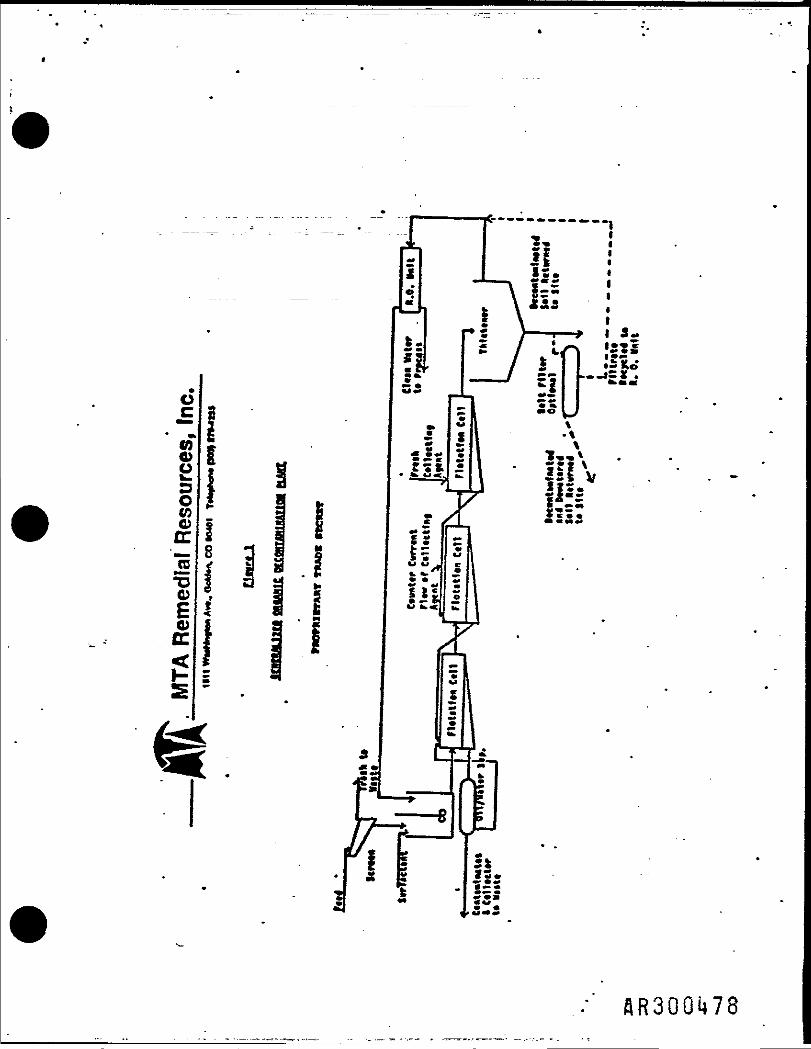
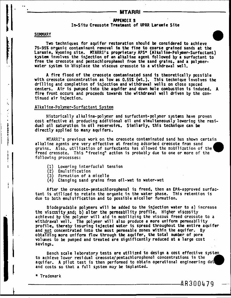
——————————— MTARRI —————————APPENDIX B
In-Situ Creosote Treatment of UPRR Laramie Site
SUMMARY
Two techniques for aquifer restoration should be considered to achieve75-955 organic contaminant removal in the fine to coarse grained sands at theLaranie, Wyoming site. KTARRI-'s proprietary APS* (Alkallne-Polymer-Surfactant)system involves the injection of an alkaline agent followed by a surfactant tofree the creosote and pentachlorophenol from the sand grains, and a polymer-water system to 'displace the viscous creosote to a withdrawal well.
A fire flood of the creosote contaminated sand Is theoretically possiblewith creosote concentration as low as 0.551 (wt.). This technique Involves thedrilling and completion of injection and withdrawal wells on close spacedcenters. Air is pumped into the aquifer and down hole combustion 1s induced. Afire front occurs and proceeds towards the withdrawal well driven by the con-tinued air injection.
Alkaline-Polymer-Surfactant System
Historically alkal ine-polyraer and surfactant-polymer systems have provencost effective at producing additional oil and simultaneously lowering the resi-dual oil saturation in oil reservoirs. Similarly, this technique can bedirectly applied to many aquifers.
KTARRI's previous work on the creosote contaminated sand has shown certainalkaline agents are very effective at freeing adsorbed creosote from sandgrains. Also, utilization of surfactants has allowed the mobilization of thefreed creosote. This "freeing" action is probably due to one or more of thefollowing processes:
(1) Lowering interfacial tension(2) Emulsification(3) Formation of a micelle(4) Changing sand grains from oil-wet to water-wet
After the creosote-pentachlorophenol is freed, then an EPA-approved surfac-tant is utilized to retain the organic in the water phase. This retention isdue to both ernul si fi cation and to possible mi cell er formation.
Biodegradable polymers will be added to the Injection water to a) increasethe viscosity.and; b) alter the permeability profile. Higher viscosityachieved by the polymer will aid in mobilizing the viscous freed creosote to awithdrawal well. The polymer will also produce a more uniform permeabilityprofile, thereby insuring injected water is spread throughout the entire aquiferand not concentrated into the most permeable zones within the aquifer. ByobtaTnTng more uniform flow through the aquifer, the total number of porevolumes to be pumped and treated are significantly reduced at a large costsavings.
Bench scale laboratory tests are utilized to design a cost effective systemto achieve lower residual creosote/pentachlorophenol concentrations in theaquifer. A pilot test is then performed to obtain operational engineeringand costs so that a full system may be implanted.
* Trademark

-——————'———————————— MTARRI ————————-—————————Aquifer Restoration by Alkaline Poljmmr Surfactant Systems
SUMMARY
Restoration of aquifers contaminated with aromatic, aliphatic and/or orga-nochlorides can be significantly sped up and achieved at less cost through theusage of fPA-approved surfactants, polymers, and alkaline agents. This tech-nological transfer from the enhanced oil recovery field 1s directly applicableand requires no further R & D.
Lower cost restoration of inorganic contaminated reservoirs can also beaccomplished by utilizing permeability modification techniques to decrease thetotal number of pore volumes necessary to achieve cleanup. Furthermore, certainEPA-approved complexing agents may be incorporated to complex and mobilize theinorganic contaminants towards withdrawal wells.
A cost savings of 50-80% compared to conventional aquifer restoration tech-niques can be achieved. Produced water containing the contaminants,surfactants, alkaline agents, and polymers can then be air stripped or carbonabsorped and the water discharged or reinjected.
I INTRODUCTION
Current groundwater cleanup involves the withdrawal of contaminated| groundwater, removal of contaminants and re-injection of the clean water on the— downstream side of a barrier system. This cleanup approach often requires the
pumping of 10-50 pore volumes of water at a very large operational cost over a2-10 year period.
The large number of pore volumes necessary to achieve cleanup is probablydue to: a) contaminant adsorption on clay and mineral particle surfaces; and b)to the possibility of a micro emulsion formation which has a lower relative per-meability than water; or c) to permeability variations in the aquifer whichresults in different groundwater flow rates.
To decrease this large number of pumped pore volumes the APS* system hasbeen developed by MTARRI to counteract clay adsorption, relative permeabilityeffects and permeability profiles within the aquifer sediments.
This APS* system is a result of technological transfer from the enhancedoil recovery field where over $500 million of R & D applications has resulted ina directly-applicable cost saving, remedial action technique, proprietary toMTARRI.
TECHNOLOGICAL DESCRIPTION
To aid in the release of organic contaminants from clay and sand particlesa 1-5 wt% concentration of KOH, NaOH, and/or N a 4$ 104 is used as a preflush. TheK* will adsorb onto clay'surfaces and displace the adsorped contaminants,whereas the OH and/or Si04"4 will result in slight saponification of certaincontaminants and a possible lowering of interfacial tensions.
* Trademark
_________________________.. fl.fi 3 p .01* 8 0.
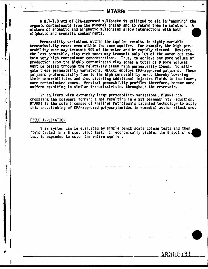
————————————————————— MTARRI ——————————————————
] A 0*1-1.0 wt% of EPA-approved sulfonate Is utilized to aid in "washing" theI organic contaminants from the mineral grains and to retain them in solution. A
mixture of aromatic and aliphatic sulfonates allow interactions with bothI aliphatic and aromatic contaminants.
Permeability variations within the aquifer results In highly.variabletransmlssivity rates even within the sane aquifer. For example, the high per-meability zone may transmit 90S of the water and be rapidly cleaned. However,the less permeable, clay rich zones may transmit only 101 of the water but con-tain very high contaminant concentrations. Thus, to achieve one pore volume ofproduction from the highly contaminated clay zones a total of 9 pore volumesmust be passed through the relatively clean high permeability zones. To miti-gate these permeability variations, MTARRI employs EPA-approved polymers. Thesepolymers preferentially flow to the high permeability zones thereby loweringtheir permeabilities and thus diverting additional injected fluids to the lower,more contaminated zones. Vertical permeability profiles therefore, become moreuniform resulting in similar transmissivities throughout the reservoir.
In aquifers with extremely large permeability variations, MTARRI tan-crosslink the polymers forming a gel resulting In a 98X permeability reduction.MTARRI is the sole licensee of Phillips Petroleum's patented technology to applythis crosslinking of EPA-approved polyacrylamides In remedial action situations.
FIELD APPLICATION
This system can be evaluated by simple bench scale column tests and thenfield tested in a 5 spot pilot test. If economically viable, the 5 spottest is expanded to cover the entire aquifer.
M.3.0..0M

PAUL B. TROST, cont.
PUBLICATIONS
One paper on contaminant containment by Polymer Dams TM.Three professional publications on mercury in the environment.One publication on exploration for naturally fractured oil/gasreservoirs.Numerous corporate in-house reports.
EDUCATION
8. S. Chemistry, University of Notre Dame, 1964.Ph.D. Geochemistry, Colorado School of Mines, 1970*
AFFILIATIONS
Member American Association of Petroleum GeologistsMember American Association of Petroleum GeochemistsMember Rocky Mountain Associates of Petroleum GeologistsMember American Society of Mining EngineersMember Geochemical SocietyMember HHCRI
flR300l»82
DR. PAUL B. TROST
PRESIDENT and CHIEF EXECUTIVE OFFICER
SUHKARY OF QUALIFICATIONS
Dr. Trost has been the President of KTA Remedial Resources, Inc.since Its inception in 1983. He has broad operational experience Indealing with hazardous materials as project manager for remedialaction and environmental compliance program Involving halogenatedhydrocarbons, pesticides, organic phosphonates, radionucleldes, andtoxic metals such as arsenic and lead. Dr. Trost has Integrated stan-dard reaedial action activities with on-site detoxification.
HISTORY
19S5 President, CEO, Director, MTA Reaedial Resources, Inc.,to Golden, CO. Responsible for all corporate financial manage-Present: nent activities and direction of technology transfers from
natural resource industries to containment and treatment ofspecific hazardous wastes.
1975 Co-founder, Partner, Martin Trost Associates, Golden, CO.to Directed and managed financial and technical aspects of1933: exploration and development of oil and mineral prospects.
Formulated and operated $13 million joint venture agreementswith Portland General Electric and Middle South Utilities.Responsible for all environmental coop!lance and treatment:
1974 Explorationist/Geochemical Consultant, Denver, CO.to . Developed, obtained financing, and operated exploration pro-1975: jects for natural resources. Consulted on migration of con-
taminated groundwater at Rocky Mountain Arsenal.
1973 Co-Manager of Exploration, Nevada Minerals, Ltd. Partnership.to Utilized geochemical techniques involving dissemination of1974: arsenic, antimony, and lead for mineral project definition.
1970 Senior Geochemist, Texas gulf. Inc. Denver, COto Conceived and conducted exploration programs utilizing1973: geochemical techniques for soil, water, rock, and plants.
.-BR300l*83
OR. ROBERT STANLET RICKARD
VICE PRESIDENT ENGINEERING and DEVELOPMENT
SUMMARY OF QUALIFICATIONS '
Dr. Rickard has consistently developed and constructed hydrome-tallurgical plants for recovery/concentration of hazardous sbustancessuch as arsenic, lead, uranium/radionucleides, and chromium. Duringthe past two years he has developed recovery systems for organicpollutants .by utilizing technology transfers from the mining andenhanced oil recovery business.
HISTORY
1985 Vice President, Engineering and Development, MTA Remedialto Resources, Inc., Golden, CO. Responsible for process 1m pro -Present: veaent and engineering design/ construction of hydrometal-
lurgical recovery of metals from hazardous wastes anddetoxification of organic hazardous materials.
1983 Independent Consultant. Developed, constructed, and managedto startup operations for arsenic recovery from toxic wastes1985: and gold/silver leaching facilities.
1982 Vice President, Western Mineral Developers, Lakewood, CO.to Developed metallurgical recovery process for unique gold ore1983: and demonstrated economic feasibility in pilot plant.
1975 .Vice President, Engineering and Development, Earth Sciences,to Golden, CO. Responsible for process development 'and engi-1981: neering construction of $14 million uranium recovery plant
and a $7 million cobalt/nickel recovery plant.
1972 Technical Asst. to Director, AHA* Extractive Metallurgicalto Lab, Golden, CO. Managed R & D f or extraction, purifi-1975: cation, and production of copper, nickel, and 0oly from
laterites.
1969 Section Chief, AKAX Extractive Metallurgical Lab, Golden, CO.to Financial and personnel management of hydrometallurgy lab.1972: Adjunct Assoc. Professer, Colorado School of Mines.
1968 Project Leader, Conoco. Team leader for phosphateto beneficiation.1969:
1966 Manager, Extractive Metallurgy Section, Union Carbide,to Niagra Falls, NY. Financial and personnel management1968: physical beneficiation and economic evaluati
ROBERT STANLEY RICKARD, cent.
1961 Project Engineer, Colorado School of Mines Researchto Foundation, Golden, CO. Evaluated and developed solvent
1964: extraction, ion exchange, and flotation on wide variety ofores.
1958 Chemical Engineer, U.S. Bureau of Reclamation* Denver, CO.to Saline water conversion by electrodlalysis and vapor-
1961: 'compression distillation.
PUBLICATIONS AHD PATENTS
Over ten journal publications on subjects ranging from flotation fun-damentals to solution mining and numerous patents in hydroaetallurgy,
EDUCATION
D.Sc. Metallurgical Engineering, Colorado School of Mines, 1967.K.S. Metallurgical Engineering, Colorado School of Mines, 1965.P.E. Geophysical Engineering, Colorado School of Mines, 1958.
'Sfi300J»85