flow structure around a square cylinder impacting a wall
TRANSCRIPT

Flow structure around a square cylinder impacting a wallChangyoung Choi, Hyun Sik Yoon, and Man Yeong Ha
Citation: Physics of Fluids (1994-present) 26, 013602 (2014); doi: 10.1063/1.4863450 View online: http://dx.doi.org/10.1063/1.4863450 View Table of Contents: http://scitation.aip.org/content/aip/journal/pof2/26/1?ver=pdfcov Published by the AIP Publishing Articles you may be interested in Flow past a square cylinder with an angle of incidence Phys. Fluids 22, 043603 (2010); 10.1063/1.3388857 Characteristics of two-dimensional flow around a rotating circular cylinder near a plane wall Phys. Fluids 19, 063601 (2007); 10.1063/1.2738608 Flow dynamics and forces associated with a cylinder rolling along a wall Phys. Fluids 18, 111701 (2006); 10.1063/1.2375062 Flows past a tiny circular cylinder at high temperature ratios and slight compressible effects on the vortexshedding Phys. Fluids 15, 1821 (2003); 10.1063/1.1575753 Effect of high rotation rates on the laminar flow around a circular cylinder Phys. Fluids 14, 3160 (2002); 10.1063/1.1492811
This article is copyrighted as indicated in the article. Reuse of AIP content is subject to the terms at: http://scitation.aip.org/termsconditions. Downloaded to IP:
199.47.112.51 On: Tue, 08 Apr 2014 13:40:05
PHYSICS OF FLUIDS 26, 013602 (2014)
Flow structure around a square cylinder impacting a wallChangyoung Choi,1 Hyun Sik Yoon,2 and Man Yeong Ha1,a)
1School of Mechanical Engineering, Pusan National University, Jang Jeon 2-Dong, GeumJeong Gu, Busan 609–735, South Korea2Global Core Research Center for Ships and Offshore Plants, Pusan National University,Jang Jeon 2-Dong, Geum Jeong Gu, Busan 609–735, South Korea
(Received 15 May 2013; accepted 15 January 2014; published online 31 January 2014)
The behavior of the flow resulting from the collision of a square cylinder with a wallwithout rebound at a Reynolds number of 200 was investigated computationally usingthe direct-forcing/fictitious domain method coupled with the finite volume method.While the emphasis of the numerical simulation was on the case in which the squarecylinder collided with the wall at different impact angles, the flow generated by theimpact of a circular cylinder was included for comparison. At a Reynolds numberof 200, we could not observe any three-dimensional effects in the fluid flow aroundthe square and circular cylinders resulting from the impact regardless of cylindershape. However, the flow structure around a square cylinder after impact was morecomplex than that around a circular cylinder. The movement of vortex tubes aroundeach cylinder after impact was influenced not only by the cylinder shape but alsoby the impact angle. The x- and y-direction drag forces on the cylinder also variedwith respect to the cylinder shape and impact angle. C© 2014 AIP Publishing LLC.[http://dx.doi.org/10.1063/1.4863450]
I. INTRODUCTION
This article presents the behavior of the fluid flow generated by a square cylinder impacting asolid wall with respect to various impact angles. The post-collision flow around a bluff body canresult in the convection of fluid towards and away from the surface as well as the resuspensionof dust particles. A bluff body colliding with a solid surface is relevant to many industrial andenvironmental applications such as fouling, enhancement of heat transfer, handling of industrialpowder, semiconductor manufacturing operations, soil erosion, resuspension of radioactive or toxicchemicals from soil, and the bulk flow of multiphase fluids (John et al.,1 Ziskind et al.,2 Lewekeet al.,3 and Thompson et al.4).
Fundamental studies on bluff bodies colliding with a wall have been investigated by manyresearchers. Eames and Dalziel5 examined in detail the wake flow following a sphere upon impactfor Reynolds numbers in the range of 300–3500. In that study, the analysis primarily focusedon the resuspension characteristics of different dust types and layer thicknesses. Joseph et al.6
experimentally examined sphere–wall collisions for Reynolds numbers between 10 and 3000. Theydemonstrated that rebound properties were primarily a function of the Stokes number and determinedthat the coefficient of restitution is a function of the Stokes number for dry collisions. Leweke et al.3, 7
and Thompson et al.8 investigated the unsteady flow resulting from the normal wall impact of asphere, revealing the existence of axisymmetric and three-dimensional vortical structures, whichwere explained by a centrifugal instability mechanism. Leweke et al.9 examined the flow inducedby a normal or oblique collision of a circular cylinder with a wall at a Reynolds number of 200.They reported that the wall effect and the height of the rebounded primary vortex varied accordingto the impact angle. They also observed a significant difference in the scales of the vortices formedafter the collision between the sphere and circular cylinder impact.
a)Author to whom correspondence should be addressed. Electronic mail: [email protected]
1070-6631/2014/26(1)/013602/14/$30.00 C©2014 AIP Publishing LLC26, 013602-1
This article is copyrighted as indicated in the article. Reuse of AIP content is subject to the terms at: http://scitation.aip.org/termsconditions. Downloaded to IP:
199.47.112.51 On: Tue, 08 Apr 2014 13:40:05
013602-2 Choi, Yoon, and Ha Phys. Fluids 26, 013602 (2014)
The flow past a rigid body moving near a wall is related to multiphase problems like the flowgenerated by dirty bubbles rising to a free surface. These phenomena are dominated by the wakevortex dynamics and play an important role in interfacial gas transfer in the ocean. The resuspensionis relevant to a wide range of problems such as resuspension caused by containers dumped into thesea, which impact the sea bed (Eames and Dalziel5). The containers might have various shapes suchas a sphere, cubic, circular cylinder, and a square cylinder. The flow around different rigid bodyshapes after the collision has a different pattern as reported by Leweke et al.9 However, accordingto our literature review, there have been few studies investigating the flow structure around a squarecylinder impacting a wall. The main purpose of the present study is to investigate the effect ofcylinder shape on the flow around the rigid body after its collision with a wall. In order to achievethis purpose, we compare the flow around the square cylinder with that around a circular cylinderfor different impact angles.
In this study, we investigate the flow induced by normal and oblique collisions of a squarecylinder with a wall at a Reynolds number of 200. This study focuses on three aspects of squarecylinder–wall interactions: (a) the formation and evolution of the vortex tube system with respect tothe cylinder shape and impact angle; (b) the schematic sketches for the flow characteristics aroundthe cylinders after impact; and (c) the variation in the drag forces on the cylinder after impact.
II. COMPUTATIONAL DETAILS
A. Numerical methods
The numerical approach for computing the three-dimensional flow structure associated withthe impact of a square cylinder on a wall is based on the direct-forcing/fictitious domain (DF/FD)method that incorporates the finite volume method.
The continuity and momentum conservation equations that govern the incompressible viscousflow in the presence of the impact of a square cylinder are expressed as
∇ · u = 0, (1)
∂u∂t
+ u · ∇u = − 1
ρ f∇ p + ν∇2u + f , (2)
where u is the fluid velocity, ρ f is the fluid density, ν is the kinematic viscosity of fluid, and f isthe volume force. A second-order accurate finite volume method spatially discretizes the governingequations, Eqs. (1) and (2). To perform the time advancement of the flow field, the fractional stepmethod proposed by Choi and Moin10 is used.
The volume force f in Eq. (2) is calculated using the DF/FD method by transforming anddiscretizing Eq. (2) as follows:
f = ∂u∂t
+ u · ∇u + 1
ρ f∇ p − ν∇2u = ∂u
∂t+ RH S, (3)
f = un+1 − un
�t+ RH Sn+1/2 = un+1 − u
�t+ u − un
�t+ RH Sn+1/2, (4)
where RHS represents the reorganization of the convective, pressure, and diffusion terms, and uis the preliminary velocity. In the discretization process, the advection terms are treated explicitlyusing the second-order Adams–Bashforth scheme, and the diffusion terms are treated implicitlyusing the second-order accurate Crank–Nicolson scheme. The preliminary velocity u must satisfythe momentum equation as follows:
u − un
�t+ RH Sn+1/2 = 0. (5)
Therefore, by substituting Eq. (5) into Eq. (4), Eq. (4) can be simplified as
un+1 = u + f �t. (6)
This article is copyrighted as indicated in the article. Reuse of AIP content is subject to the terms at: http://scitation.aip.org/termsconditions. Downloaded to IP:
199.47.112.51 On: Tue, 08 Apr 2014 13:40:05
013602-3 Choi, Yoon, and Ha Phys. Fluids 26, 013602 (2014)
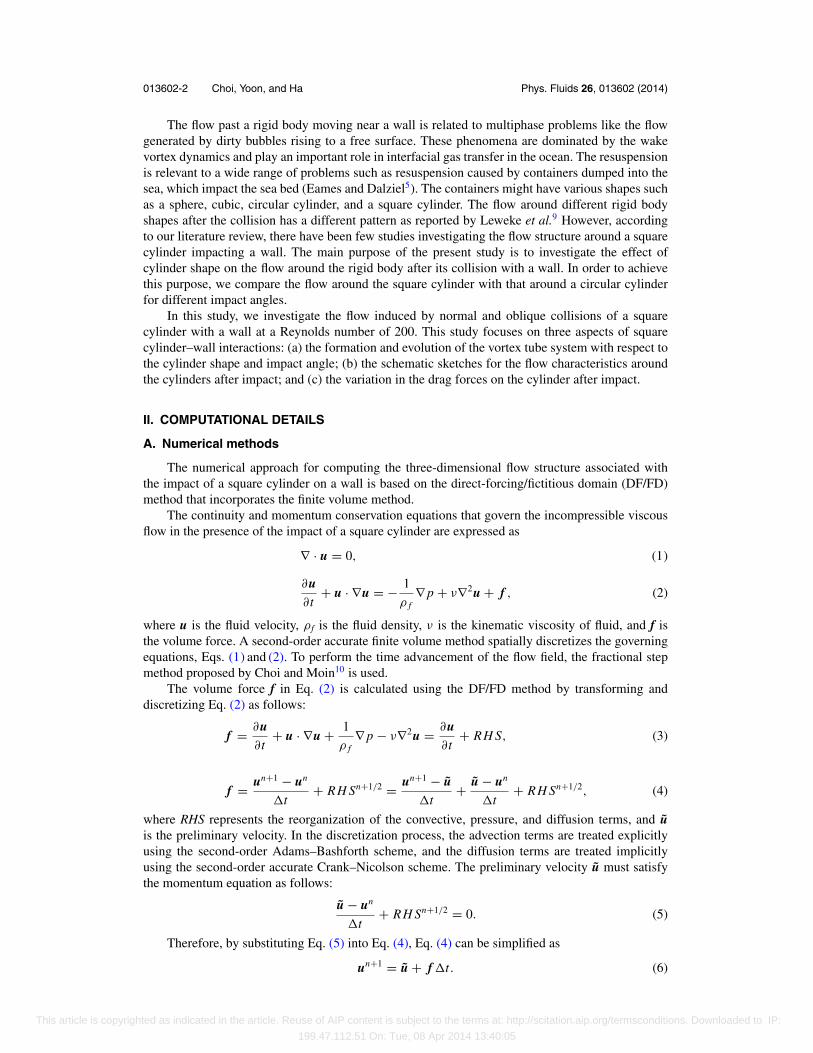
FIG. 1. Problem definition and parameters.
Further details on the calculation of the volume force f are given in Choi et al.11
B. Computational conditions
Figure 1 shows the problem definition and the parameters considered in this study. The squarecylinder starts from rest and travels a distance L through a fluid at a constant velocity U towardsa wall. The cylinder stops at the moment of contact with the wall, at which point the x-directionalposition of the center of the cylinder is zero regardless of the impact angle. In the present study, wedo not consider the rolling and translation motions of the cylinder after impact.
The width of the square cylinder D is used as the characteristic length to define thenondimensional running distance L/D, Reynolds number Re = UD/ν, nondimensional vorticityζ = D(∇ × u)/U , and the nondimensional advection time τ = tU/D, where τ = 0 at the time ofimpact. When oblique impacts are investigated, the angle α between the cylinder trajectory and thedirection normal to the wall represents a third parameter.
Similar to Leweke et al.,9 we focused our study on cases in which the wake behind the squarecylinder remains symmetric up to the time of impact. Thus, based on the results of Leweke et al.9
and the preliminary numerical simulation for the square cylinder impact, L/D = 4 is designated asthe nondimensional running distance.
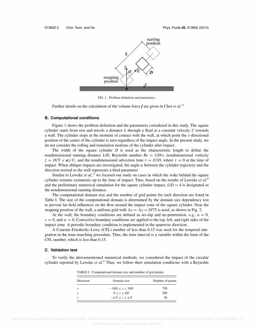
The computational domain size and the number of grid points for each direction are listed inTable I. The size of the computational domain is determined by the domain size dependency testto prevent far-field influences on the flow around the impact zone of the square cylinder. Near thestopping position of the wall, a uniform grid with �x = �y = D/75 is used, as shown in Fig. 2.
At the wall, the boundary conditions are defined as no-slip and no-penetration, e.g., u = 0,v = 0, and w = 0. Convective boundary conditions are applied to the top, left, and right sides of theimpact zone. A periodic boundary condition is implemented in the spanwise direction.
A Courant–Friedrichs–Lewy (CFL) number of less than 0.15 was used for the temporal inte-gration in the time-marching procedure. Thus, the time interval is a variable within the limit of theCFL number, which is less than 0.15.
C. Validation test
To verify the abovementioned numerical methods, we considered the impact of the circularcylinder reported by Leweke et al.9 Thus, we follow their simulation conditions with a Reynolds
TABLE I. Computational domain size and number of grid points.
Direction Domain size Number of points
x −10D ≤ x ≤ 10D 750y 0 ≤ y ≤ 6D 280z −π /2 ≤ z ≤ π /2 48
This article is copyrighted as indicated in the article. Reuse of AIP content is subject to the terms at: http://scitation.aip.org/termsconditions. Downloaded to IP:
199.47.112.51 On: Tue, 08 Apr 2014 13:40:05
013602-4 Choi, Yoon, and Ha Phys. Fluids 26, 013602 (2014)
FIG. 2. Distribution of grid points (a) for the entire domain and (b) near the stopping position and wall.
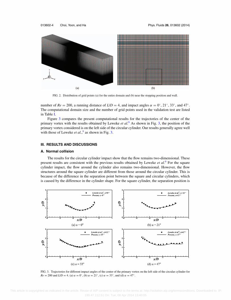
number of Re = 200, a running distance of L/D = 4, and impact angles α = 0◦, 21◦, 33◦, and 47◦.The computational domain size and the number of grid points used in the validation test are listedin Table I.
Figure 3 compares the present computational results for the trajectories of the center of theprimary vortex with the results obtained by Leweke et al.9 As shown in Fig. 3, the position of theprimary vortex considered is on the left side of the circular cylinder. Our results generally agree wellwith those of Leweke et al.,9 as shown in Fig. 3.
III. RESULTS AND DISCUSSIONS
A. Normal collision
The results for the circular cylinder impact show that the flow remains two-dimensional. Thesepresent results are consistent with the previous results obtained by Leweke et al.9 For the squarecylinder impact, the flow around the cylinder also remains two-dimensional. However, the flowstructures around the square cylinder are different from those around the circular cylinder. This isbecause of the difference in the separation point between the square and circular cylinders, whichis caused by the difference in the cylinder shape. For the square cylinder, the separation position is
FIG. 3. Trajectories for different impact angles of the center of the primary vortex on the left side of the circular cylinder forRe = 200 and L/D = 4. (a) α = 0◦, (b) α = 21◦, (c) α = 33◦, and (d) α = 47◦.
This article is copyrighted as indicated in the article. Reuse of AIP content is subject to the terms at: http://scitation.aip.org/termsconditions. Downloaded to IP:
199.47.112.51 On: Tue, 08 Apr 2014 13:40:05
013602-5 Choi, Yoon, and Ha Phys. Fluids 26, 013602 (2014)
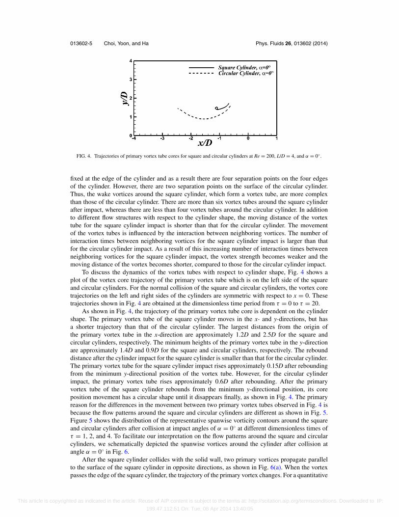
FIG. 4. Trajectories of primary vortex tube cores for square and circular cylinders at Re = 200, L/D = 4, and α = 0◦.
fixed at the edge of the cylinder and as a result there are four separation points on the four edgesof the cylinder. However, there are two separation points on the surface of the circular cylinder.Thus, the wake vortices around the square cylinder, which form a vortex tube, are more complexthan those of the circular cylinder. There are more than six vortex tubes around the square cylinderafter impact, whereas there are less than four vortex tubes around the circular cylinder. In additionto different flow structures with respect to the cylinder shape, the moving distance of the vortextube for the square cylinder impact is shorter than that for the circular cylinder. The movementof the vortex tubes is influenced by the interaction between neighboring vortices. The number ofinteraction times between neighboring vortices for the square cylinder impact is larger than thatfor the circular cylinder impact. As a result of this increasing number of interaction times betweenneighboring vortices for the square cylinder impact, the vortex strength becomes weaker and themoving distance of the vortex becomes shorter, compared to those for the circular cylinder impact.
To discuss the dynamics of the vortex tubes with respect to cylinder shape, Fig. 4 shows aplot of the vortex core trajectory of the primary vortex tube which is on the left side of the squareand circular cylinders. For the normal collision of the square and circular cylinders, the vortex coretrajectories on the left and right sides of the cylinders are symmetric with respect to x = 0. Thesetrajectories shown in Fig. 4 are obtained at the dimensionless time period from τ = 0 to τ = 20.
As shown in Fig. 4, the trajectory of the primary vortex tube core is dependent on the cylindershape. The primary vortex tube of the square cylinder moves in the x- and y-directions, but hasa shorter trajectory than that of the circular cylinder. The largest distances from the origin ofthe primary vortex tube in the x-direction are approximately 1.2D and 2.5D for the square andcircular cylinders, respectively. The minimum heights of the primary vortex tube in the y-directionare approximately 1.4D and 0.9D for the square and circular cylinders, respectively. The rebounddistance after the cylinder impact for the square cylinder is smaller than that for the circular cylinder.The primary vortex tube for the square cylinder impact rises approximately 0.15D after reboundingfrom the minimum y-directional position of the vortex tube. However, for the circular cylinderimpact, the primary vortex tube rises approximately 0.6D after rebounding. After the primaryvortex tube of the square cylinder rebounds from the minimum y-directional position, its coreposition movement has a circular shape until it disappears finally, as shown in Fig. 4. The primaryreason for the differences in the movement between two primary vortex tubes observed in Fig. 4 isbecause the flow patterns around the square and circular cylinders are different as shown in Fig. 5.Figure 5 shows the distribution of the representative spanwise vorticity contours around the squareand circular cylinders after collision at impact angles of α = 0◦ at different dimensionless times ofτ = 1, 2, and 4. To facilitate our interpretation on the flow patterns around the square and circularcylinders, we schematically depicted the spanwise vortices around the cylinder after collision atangle α = 0◦ in Fig. 6.
After the square cylinder collides with the solid wall, two primary vortices propagate parallelto the surface of the square cylinder in opposite directions, as shown in Fig. 6(a). When the vortexpasses the edge of the square cylinder, the trajectory of the primary vortex changes. For a quantitative
This article is copyrighted as indicated in the article. Reuse of AIP content is subject to the terms at: http://scitation.aip.org/termsconditions. Downloaded to IP:
199.47.112.51 On: Tue, 08 Apr 2014 13:40:05
013602-6 Choi, Yoon, and Ha Phys. Fluids 26, 013602 (2014)
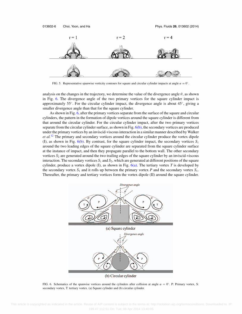
FIG. 5. Representative spanwise vorticity contours for square and circular cylinder impacts at angle α = 0◦.
analysis on the changes in the trajectory, we determine the value of the divergence angle θ , as shownin Fig. 6. The divergence angle of the two primary vortices for the square cylinder impact isapproximately 55◦. For the circular cylinder impact, the divergence angle is about 45◦, giving asmaller divergence angle than that for the square cylinder.
As shown in Fig. 6, after the primary vortices separate from the surface of the square and circularcylinders, the pattern in the formation of dipole vortices around the square cylinder is different fromthat around the circular cylinder. For the circular cylinder impact, after the two primary vorticesseparate from the circular cylinder surface, as shown in Fig. 6(b), the secondary vortices are producedunder the primary vortices by an inviscid-viscous interaction in a similar manner described by Walkeret al.12 The primary and secondary vortices around the circular cylinder produce the vortex dipole(I), as shown in Fig. 6(b). By contrast, for the square cylinder impact, the secondary vortices S1
around the two leading edges of the square cylinder are separated from the square cylinder surfaceat the instance of impact, and then they propagate parallel to the bottom wall. The other secondaryvortices S2 are generated around the two trailing edges of the square cylinder by an inviscid-viscousinteraction. The secondary vortices S1 and S2, which are generated at different positions of the squarecylinder, produce a vortex dipole (I), as shown in Fig. 6(a). The tertiary vortex T is developed bythe secondary vortex S1 and it rolls up between the primary vortex P and the secondary vortex S1.Thereafter, the primary and tertiary vortices form the vortex dipole (II) around the square cylinder.
FIG. 6. Schematics of the spanwise vortices around the cylinders after collision at angle α = 0◦. P: Primary vortex, S:secondary vortex, T: tertiary vortex. (a) Square cylinder and (b) circular cylinder.
This article is copyrighted as indicated in the article. Reuse of AIP content is subject to the terms at: http://scitation.aip.org/termsconditions. Downloaded to IP:
199.47.112.51 On: Tue, 08 Apr 2014 13:40:05
013602-7 Choi, Yoon, and Ha Phys. Fluids 26, 013602 (2014)
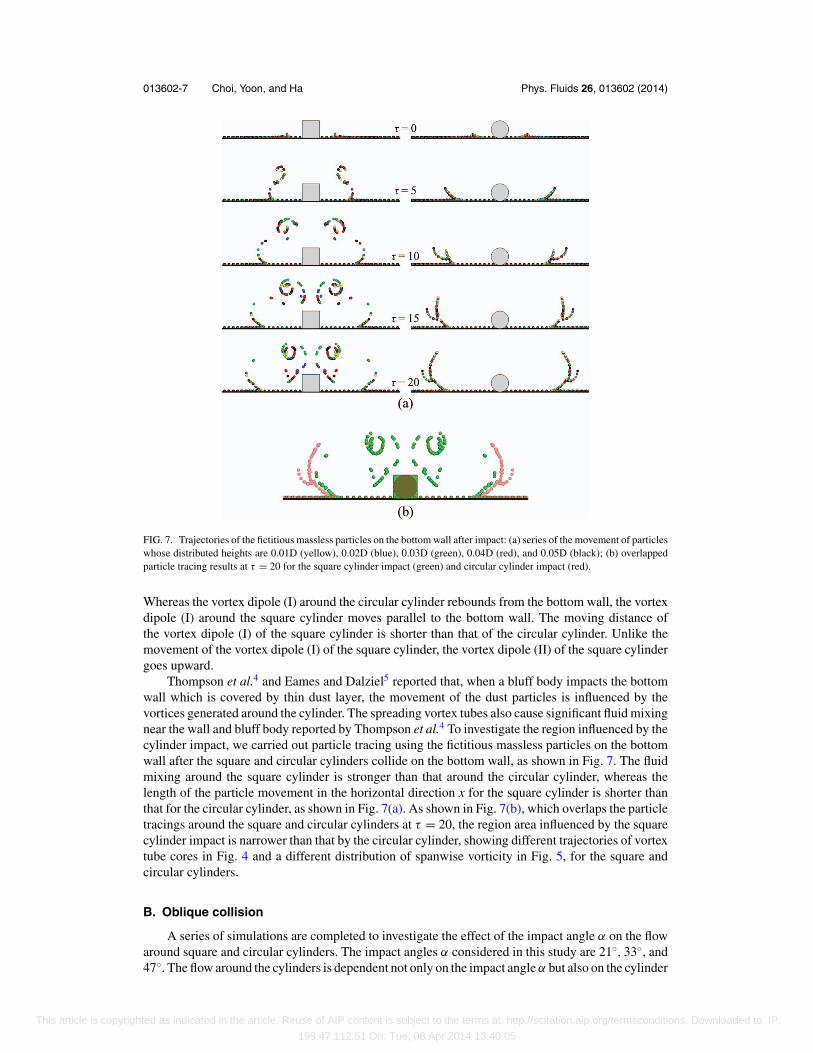
FIG. 7. Trajectories of the fictitious massless particles on the bottom wall after impact: (a) series of the movement of particleswhose distributed heights are 0.01D (yellow), 0.02D (blue), 0.03D (green), 0.04D (red), and 0.05D (black); (b) overlappedparticle tracing results at τ = 20 for the square cylinder impact (green) and circular cylinder impact (red).
Whereas the vortex dipole (I) around the circular cylinder rebounds from the bottom wall, the vortexdipole (I) around the square cylinder moves parallel to the bottom wall. The moving distance ofthe vortex dipole (I) of the square cylinder is shorter than that of the circular cylinder. Unlike themovement of the vortex dipole (I) of the square cylinder, the vortex dipole (II) of the square cylindergoes upward.
Thompson et al.4 and Eames and Dalziel5 reported that, when a bluff body impacts the bottomwall which is covered by thin dust layer, the movement of the dust particles is influenced by thevortices generated around the cylinder. The spreading vortex tubes also cause significant fluid mixingnear the wall and bluff body reported by Thompson et al.4 To investigate the region influenced by thecylinder impact, we carried out particle tracing using the fictitious massless particles on the bottomwall after the square and circular cylinders collide on the bottom wall, as shown in Fig. 7. The fluidmixing around the square cylinder is stronger than that around the circular cylinder, whereas thelength of the particle movement in the horizontal direction x for the square cylinder is shorter thanthat for the circular cylinder, as shown in Fig. 7(a). As shown in Fig. 7(b), which overlaps the particletracings around the square and circular cylinders at τ = 20, the region area influenced by the squarecylinder impact is narrower than that by the circular cylinder, showing different trajectories of vortextube cores in Fig. 4 and a different distribution of spanwise vorticity in Fig. 5, for the square andcircular cylinders.
B. Oblique collision
A series of simulations are completed to investigate the effect of the impact angle α on the flowaround square and circular cylinders. The impact angles α considered in this study are 21◦, 33◦, and47◦. The flow around the cylinders is dependent not only on the impact angle α but also on the cylinder
This article is copyrighted as indicated in the article. Reuse of AIP content is subject to the terms at: http://scitation.aip.org/termsconditions. Downloaded to IP:
199.47.112.51 On: Tue, 08 Apr 2014 13:40:05
013602-8 Choi, Yoon, and Ha Phys. Fluids 26, 013602 (2014)
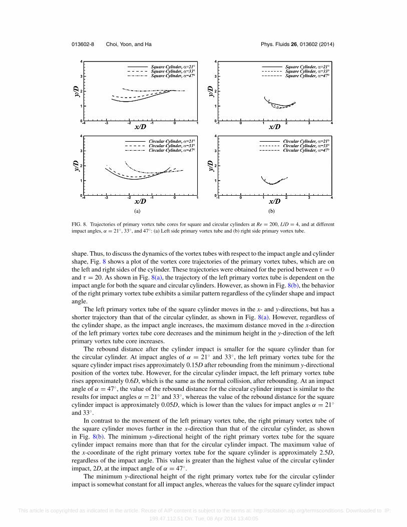
FIG. 8. Trajectories of primary vortex tube cores for square and circular cylinders at Re = 200, L/D = 4, and at differentimpact angles, α = 21◦, 33◦, and 47◦: (a) Left side primary vortex tube and (b) right side primary vortex tube.
shape. Thus, to discuss the dynamics of the vortex tubes with respect to the impact angle and cylindershape, Fig. 8 shows a plot of the vortex core trajectories of the primary vortex tubes, which are onthe left and right sides of the cylinder. These trajectories were obtained for the period between τ = 0and τ = 20. As shown in Fig. 8(a), the trajectory of the left primary vortex tube is dependent on theimpact angle for both the square and circular cylinders. However, as shown in Fig. 8(b), the behaviorof the right primary vortex tube exhibits a similar pattern regardless of the cylinder shape and impactangle.
The left primary vortex tube of the square cylinder moves in the x- and y-directions, but has ashorter trajectory than that of the circular cylinder, as shown in Fig. 8(a). However, regardless ofthe cylinder shape, as the impact angle increases, the maximum distance moved in the x-directionof the left primary vortex tube core decreases and the minimum height in the y-direction of the leftprimary vortex tube core increases.
The rebound distance after the cylinder impact is smaller for the square cylinder than forthe circular cylinder. At impact angles of α = 21◦ and 33◦, the left primary vortex tube for thesquare cylinder impact rises approximately 0.15D after rebounding from the minimum y-directionalposition of the vortex tube. However, for the circular cylinder impact, the left primary vortex tuberises approximately 0.6D, which is the same as the normal collision, after rebounding. At an impactangle of α = 47◦, the value of the rebound distance for the circular cylinder impact is similar to theresults for impact angles α = 21◦ and 33◦, whereas the value of the rebound distance for the squarecylinder impact is approximately 0.05D, which is lower than the values for impact angles α = 21◦
and 33◦.In contrast to the movement of the left primary vortex tube, the right primary vortex tube of
the square cylinder moves further in the x-direction than that of the circular cylinder, as shownin Fig. 8(b). The minimum y-directional height of the right primary vortex tube for the squarecylinder impact remains more than that for the circular cylinder impact. The maximum value ofthe x-coordinate of the right primary vortex tube for the square cylinder is approximately 2.5D,regardless of the impact angle. This value is greater than the highest value of the circular cylinderimpact, 2D, at the impact angle of α = 47◦.
The minimum y-directional height of the right primary vortex tube for the circular cylinderimpact is somewhat constant for all impact angles, whereas the values for the square cylinder impact
This article is copyrighted as indicated in the article. Reuse of AIP content is subject to the terms at: http://scitation.aip.org/termsconditions. Downloaded to IP:
199.47.112.51 On: Tue, 08 Apr 2014 13:40:05
013602-9 Choi, Yoon, and Ha Phys. Fluids 26, 013602 (2014)
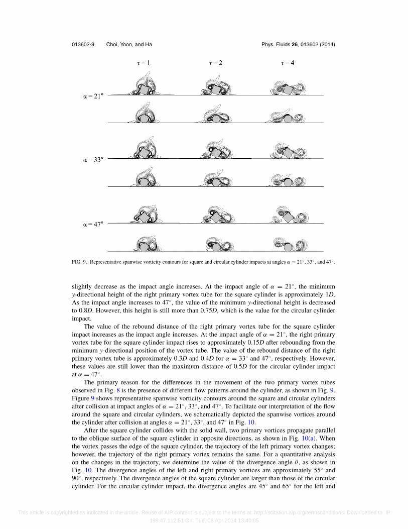
FIG. 9. Representative spanwise vorticity contours for square and circular cylinder impacts at angles α = 21◦, 33◦, and 47◦.
slightly decrease as the impact angle increases. At the impact angle of α = 21◦, the minimumy-directional height of the right primary vortex tube for the square cylinder is approximately 1D.As the impact angle increases to 47◦, the value of the minimum y-directional height is decreasedto 0.8D. However, this height is still more than 0.75D, which is the value for the circular cylinderimpact.
The value of the rebound distance of the right primary vortex tube for the square cylinderimpact increases as the impact angle increases. At the impact angle of α = 21◦, the right primaryvortex tube for the square cylinder impact rises to approximately 0.15D after rebounding from theminimum y-directional position of the vortex tube. The value of the rebound distance of the rightprimary vortex tube is approximately 0.3D and 0.4D for α = 33◦ and 47◦, respectively. However,these values are still lower than the maximum distance of 0.5D for the circular cylinder impactat α = 47◦.
The primary reason for the differences in the movement of the two primary vortex tubesobserved in Fig. 8 is the presence of different flow patterns around the cylinder, as shown in Fig. 9.Figure 9 shows representative spanwise vorticity contours around the square and circular cylindersafter collision at impact angles of α = 21◦, 33◦, and 47◦. To facilitate our interpretation of the flowaround the square and circular cylinders, we schematically depicted the spanwise vortices aroundthe cylinder after collision at angles α = 21◦, 33◦, and 47◦ in Fig. 10.
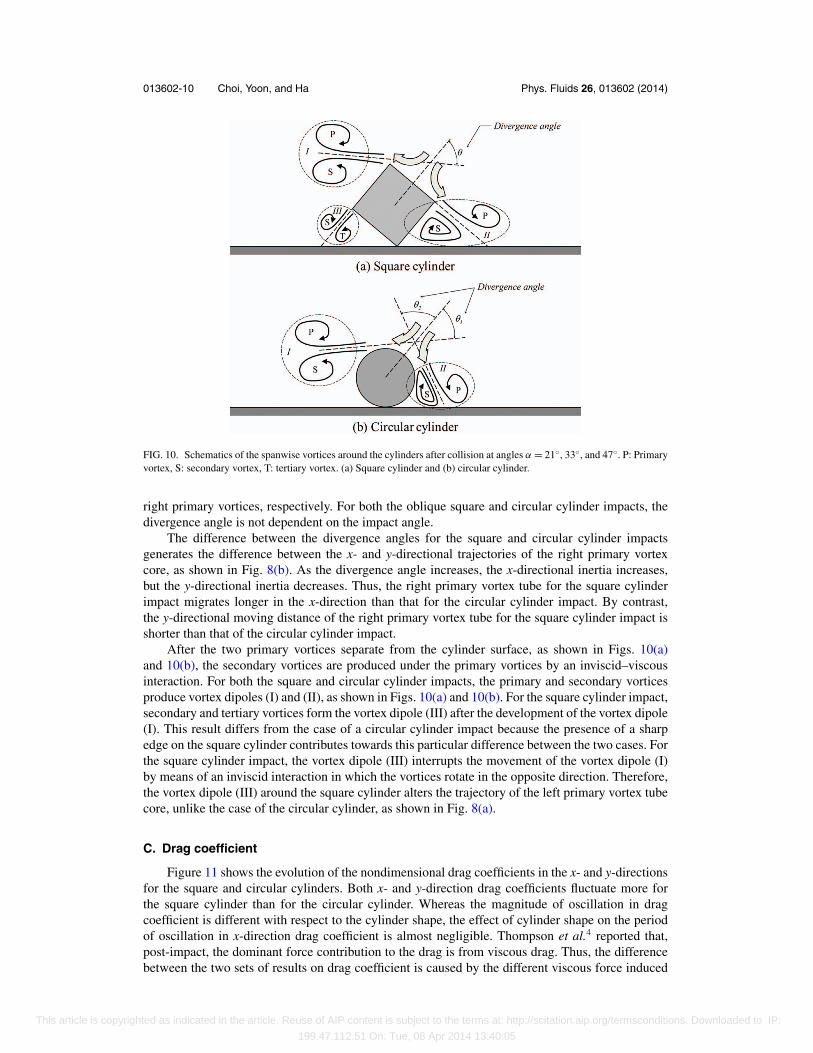
After the square cylinder collides with the solid wall, two primary vortices propagate parallelto the oblique surface of the square cylinder in opposite directions, as shown in Fig. 10(a). Whenthe vortex passes the edge of the square cylinder, the trajectory of the left primary vortex changes;however, the trajectory of the right primary vortex remains the same. For a quantitative analysison the changes in the trajectory, we determine the value of the divergence angle θ , as shown inFig. 10. The divergence angles of the left and right primary vortices are approximately 55◦ and90◦, respectively. The divergence angles of the square cylinder are larger than those of the circularcylinder. For the circular cylinder impact, the divergence angles are 45◦ and 65◦ for the left and
This article is copyrighted as indicated in the article. Reuse of AIP content is subject to the terms at: http://scitation.aip.org/termsconditions. Downloaded to IP:
199.47.112.51 On: Tue, 08 Apr 2014 13:40:05
013602-10 Choi, Yoon, and Ha Phys. Fluids 26, 013602 (2014)
FIG. 10. Schematics of the spanwise vortices around the cylinders after collision at angles α = 21◦, 33◦, and 47◦. P: Primaryvortex, S: secondary vortex, T: tertiary vortex. (a) Square cylinder and (b) circular cylinder.
right primary vortices, respectively. For both the oblique square and circular cylinder impacts, thedivergence angle is not dependent on the impact angle.
The difference between the divergence angles for the square and circular cylinder impactsgenerates the difference between the x- and y-directional trajectories of the right primary vortexcore, as shown in Fig. 8(b). As the divergence angle increases, the x-directional inertia increases,but the y-directional inertia decreases. Thus, the right primary vortex tube for the square cylinderimpact migrates longer in the x-direction than that for the circular cylinder impact. By contrast,the y-directional moving distance of the right primary vortex tube for the square cylinder impact isshorter than that of the circular cylinder impact.
After the two primary vortices separate from the cylinder surface, as shown in Figs. 10(a)and 10(b), the secondary vortices are produced under the primary vortices by an inviscid–viscousinteraction. For both the square and circular cylinder impacts, the primary and secondary vorticesproduce vortex dipoles (I) and (II), as shown in Figs. 10(a) and 10(b). For the square cylinder impact,secondary and tertiary vortices form the vortex dipole (III) after the development of the vortex dipole(I). This result differs from the case of a circular cylinder impact because the presence of a sharpedge on the square cylinder contributes towards this particular difference between the two cases. Forthe square cylinder impact, the vortex dipole (III) interrupts the movement of the vortex dipole (I)by means of an inviscid interaction in which the vortices rotate in the opposite direction. Therefore,the vortex dipole (III) around the square cylinder alters the trajectory of the left primary vortex tubecore, unlike the case of the circular cylinder, as shown in Fig. 8(a).
C. Drag coefficient
Figure 11 shows the evolution of the nondimensional drag coefficients in the x- and y-directionsfor the square and circular cylinders. Both x- and y-direction drag coefficients fluctuate more forthe square cylinder than for the circular cylinder. Whereas the magnitude of oscillation in dragcoefficient is different with respect to the cylinder shape, the effect of cylinder shape on the periodof oscillation in x-direction drag coefficient is almost negligible. Thompson et al.4 reported that,post-impact, the dominant force contribution to the drag is from viscous drag. Thus, the differencebetween the two sets of results on drag coefficient is caused by the different viscous force induced
This article is copyrighted as indicated in the article. Reuse of AIP content is subject to the terms at: http://scitation.aip.org/termsconditions. Downloaded to IP:
199.47.112.51 On: Tue, 08 Apr 2014 13:40:05
013602-11 Choi, Yoon, and Ha Phys. Fluids 26, 013602 (2014)
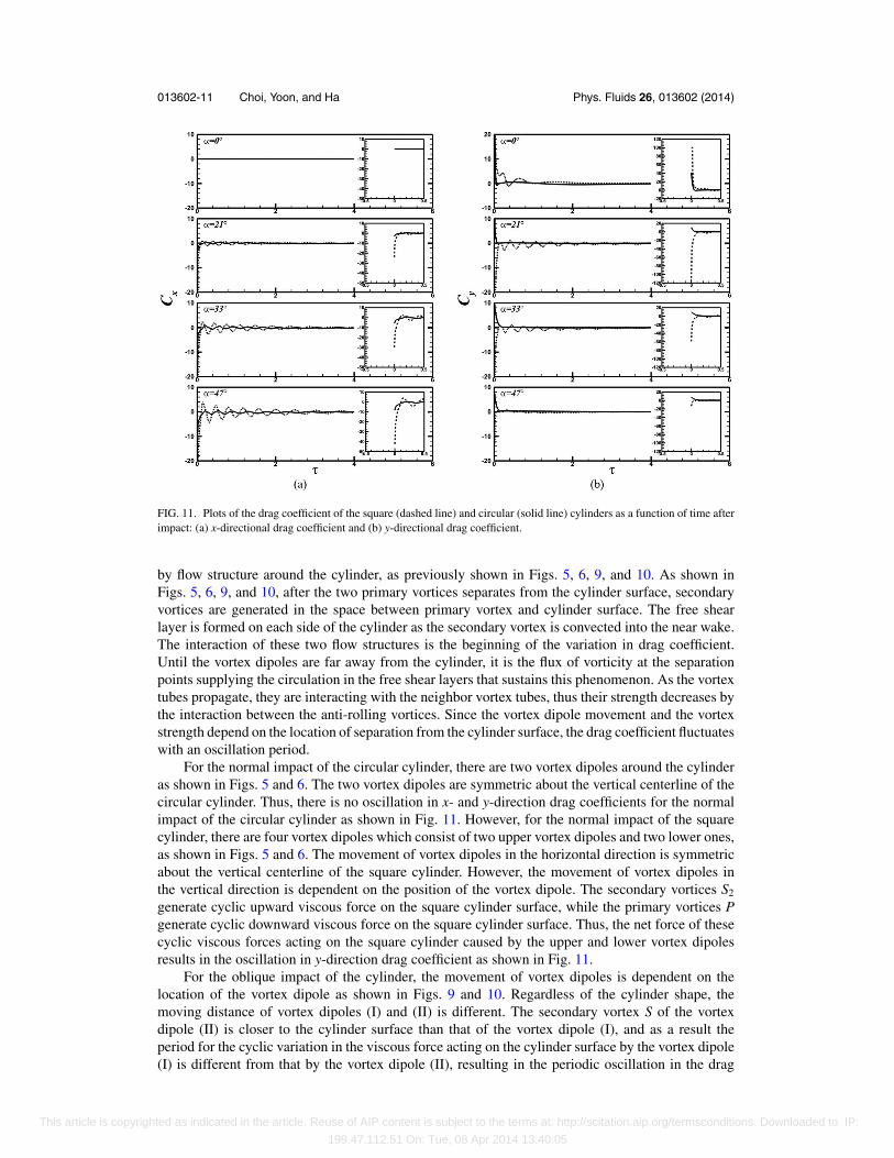
FIG. 11. Plots of the drag coefficient of the square (dashed line) and circular (solid line) cylinders as a function of time afterimpact: (a) x-directional drag coefficient and (b) y-directional drag coefficient.
by flow structure around the cylinder, as previously shown in Figs. 5, 6, 9, and 10. As shown inFigs. 5, 6, 9, and 10, after the two primary vortices separates from the cylinder surface, secondaryvortices are generated in the space between primary vortex and cylinder surface. The free shearlayer is formed on each side of the cylinder as the secondary vortex is convected into the near wake.The interaction of these two flow structures is the beginning of the variation in drag coefficient.Until the vortex dipoles are far away from the cylinder, it is the flux of vorticity at the separationpoints supplying the circulation in the free shear layers that sustains this phenomenon. As the vortextubes propagate, they are interacting with the neighbor vortex tubes, thus their strength decreases bythe interaction between the anti-rolling vortices. Since the vortex dipole movement and the vortexstrength depend on the location of separation from the cylinder surface, the drag coefficient fluctuateswith an oscillation period.
For the normal impact of the circular cylinder, there are two vortex dipoles around the cylinderas shown in Figs. 5 and 6. The two vortex dipoles are symmetric about the vertical centerline of thecircular cylinder. Thus, there is no oscillation in x- and y-direction drag coefficients for the normalimpact of the circular cylinder as shown in Fig. 11. However, for the normal impact of the squarecylinder, there are four vortex dipoles which consist of two upper vortex dipoles and two lower ones,as shown in Figs. 5 and 6. The movement of vortex dipoles in the horizontal direction is symmetricabout the vertical centerline of the square cylinder. However, the movement of vortex dipoles inthe vertical direction is dependent on the position of the vortex dipole. The secondary vortices S2
generate cyclic upward viscous force on the square cylinder surface, while the primary vortices Pgenerate cyclic downward viscous force on the square cylinder surface. Thus, the net force of thesecyclic viscous forces acting on the square cylinder caused by the upper and lower vortex dipolesresults in the oscillation in y-direction drag coefficient as shown in Fig. 11.
For the oblique impact of the cylinder, the movement of vortex dipoles is dependent on thelocation of the vortex dipole as shown in Figs. 9 and 10. Regardless of the cylinder shape, themoving distance of vortex dipoles (I) and (II) is different. The secondary vortex S of the vortexdipole (II) is closer to the cylinder surface than that of the vortex dipole (I), and as a result theperiod for the cyclic variation in the viscous force acting on the cylinder surface by the vortex dipole(I) is different from that by the vortex dipole (II), resulting in the periodic oscillation in the drag
This article is copyrighted as indicated in the article. Reuse of AIP content is subject to the terms at: http://scitation.aip.org/termsconditions. Downloaded to IP:
199.47.112.51 On: Tue, 08 Apr 2014 13:40:05
013602-12 Choi, Yoon, and Ha Phys. Fluids 26, 013602 (2014)
coefficient as shown in Fig. 11. Even though there is the vortex dipole (III) for the square cylinder,the oscillation period in x-direction drag coefficient is similar to that for the circular cylinder asshown in Fig. 11. Thus, it can be supposed that the period for the variation in the viscous force actingon the cylinder surface by the vortex dipole (III) is similar to that by the vortex dipole (II) for theoblique impact of the square cylinder. In general, the fluid flow around the square cylinder is morecomplex, so the number of interaction times between neighboring vortices increases. Therefore, theoscillation in drag coefficient of the square cylinder is larger than that of the circular cylinder asshown in Fig. 11.
For the normal collision of square and circular cylinders, the x-direction drag coefficient is zerodue to the symmetric flow around the cylinder after collision. However, for the oblique collision,regardless of the cylinder shape, the x-direction drag coefficient has a negative value at impact andconverges slowly to zero as the flow around the cylinder subsides, as shown in Fig. 11(a). As theimpact angle increases, the magnitude of the initial value of the x-direction drag coefficient increases.However, for the same impact angle, the magnitude of x-direction drag coefficients for the squarecylinder is higher than that for the circular cylinder. In a more physically realistic simulation, thismay have implications for the post-collision rolling or sliding movement of the cylinder that wouldoccur as with the previous research by Eames and Dalziel5 and Glowinski et al.13 Thus, regardless ofthe cylinder shape, the rolling or sliding movement of the cylinder may become more considerableas the impact angle increases. However, in this study, the cylinder was fixed after impact, so that theinteraction between the vortices around the cylinder generates an oscillation in the x-direction dragforces.
Unlike the x-direction drag coefficient, the y-direction drag coefficient varies according to thecylinder shape and the impact angle, as shown in Fig. 11(b). For the normal collision of the cylinder,the initial value of the y-direction drag coefficient is positive. The magnitude and the oscillationamplitude of the y-direction drag coefficient of the square cylinder are greater than that of the circularcylinder due to the difference in the contact area between the cylinder and bottom wall. It is expectedthat the rebound height of the square cylinder after collision at angle α = 0◦ would be higher than thatof the circular cylinder in a more physically realistic simulation. For the oblique collision, the signand magnitude of the y-direction drag coefficient are dependent on the cylinder shape and impactangle, respectively. For the circular cylinder, the value of the y-direction drag coefficient is positiveand almost constant for oblique collisions. This result differs from the case of the square cylinder, inwhich the value of the y-direction drag coefficient is negative and the magnitude of the y-directiondrag coefficient decreases as the impact angle increases. Therefore, in a more physically realisticsimulation, the circular cylinder would rebound at impact and the rebound height would increasewhen the impact angle is high. Conversely, the square cylinder would not rebound at impact.
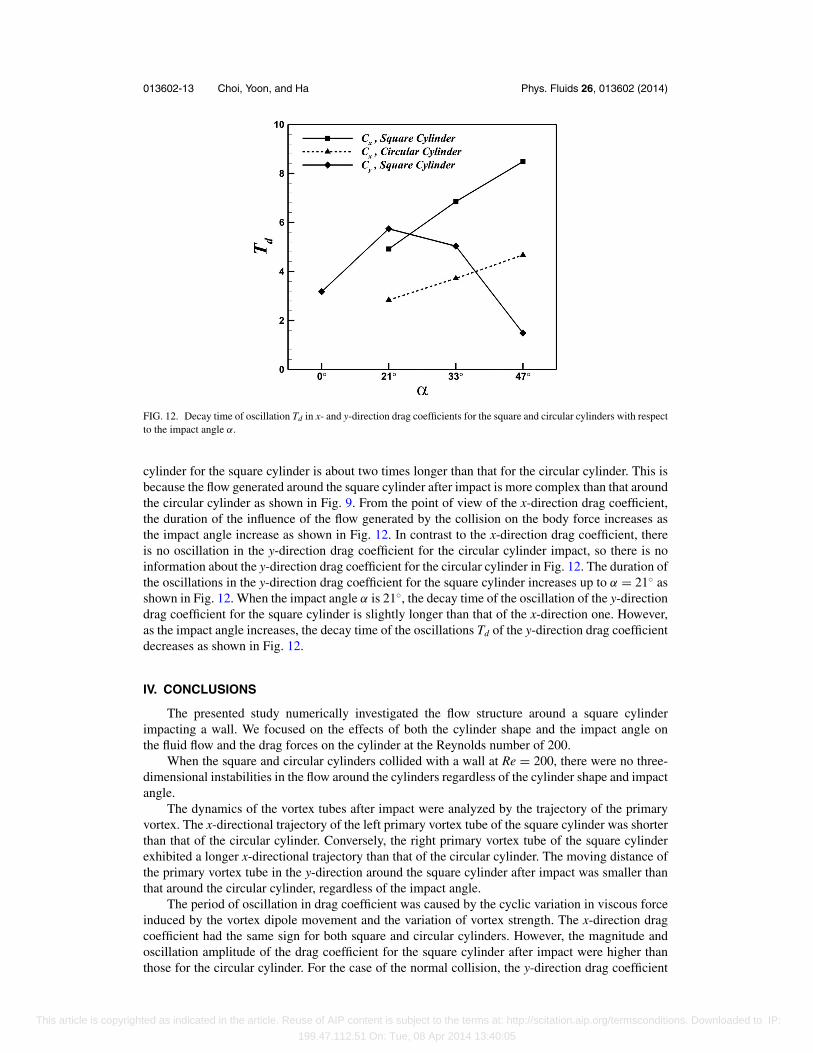
The oscillation in the x- and y-direction drag coefficients exits until the effect of the flow aroundthe cylinder on the cylinder disappears or becomes sufficiently small. Thus, as shown in Fig. 12,the decay time of oscillations in the x- and y-direction drag coefficient is calculated to analyze howlong the flow generated by the collision between the cylinder and the bottom wall is influence bythe cylinder. The decay time of oscillation Td is calculated as follows:
Td = −T ln ξ, (7)
where T is the time constant of the damped oscillation of the drag coefficient and ξ is the referenceamplitude for the end of oscillation. The time constant T is calculated by T = −(τ 1 − τ 2)/ln (c1/c2),where τ and c represent the arbitrary dimensionless time and the value of the drag coefficient,respectively. In this study, the reference amplitude ξ for the end of oscillation is defined as theamplitude when the variation of the amplitude is less than 1%. When the amplitude of the oscillationsis less than the reference amplitude ξ , the flow around the cylinder surface has disappeared almostentirely, so the cylinder is scarcely influenced by the flow around the cylinder. Thus, from the endof the decay time Td, physically the effect of the fluid flow in the vicinity of the cylinder on bodyforces is negligible.
As shown in Fig. 12, the square cylinder is influenced by the flow generated by the collisionlonger than the circular cylinder. Based on the decay time of oscillation Td in x-direction dragcoefficient in Fig. 12, the duration of the influence of the flow generated by the collision on the
This article is copyrighted as indicated in the article. Reuse of AIP content is subject to the terms at: http://scitation.aip.org/termsconditions. Downloaded to IP:
199.47.112.51 On: Tue, 08 Apr 2014 13:40:05
013602-13 Choi, Yoon, and Ha Phys. Fluids 26, 013602 (2014)
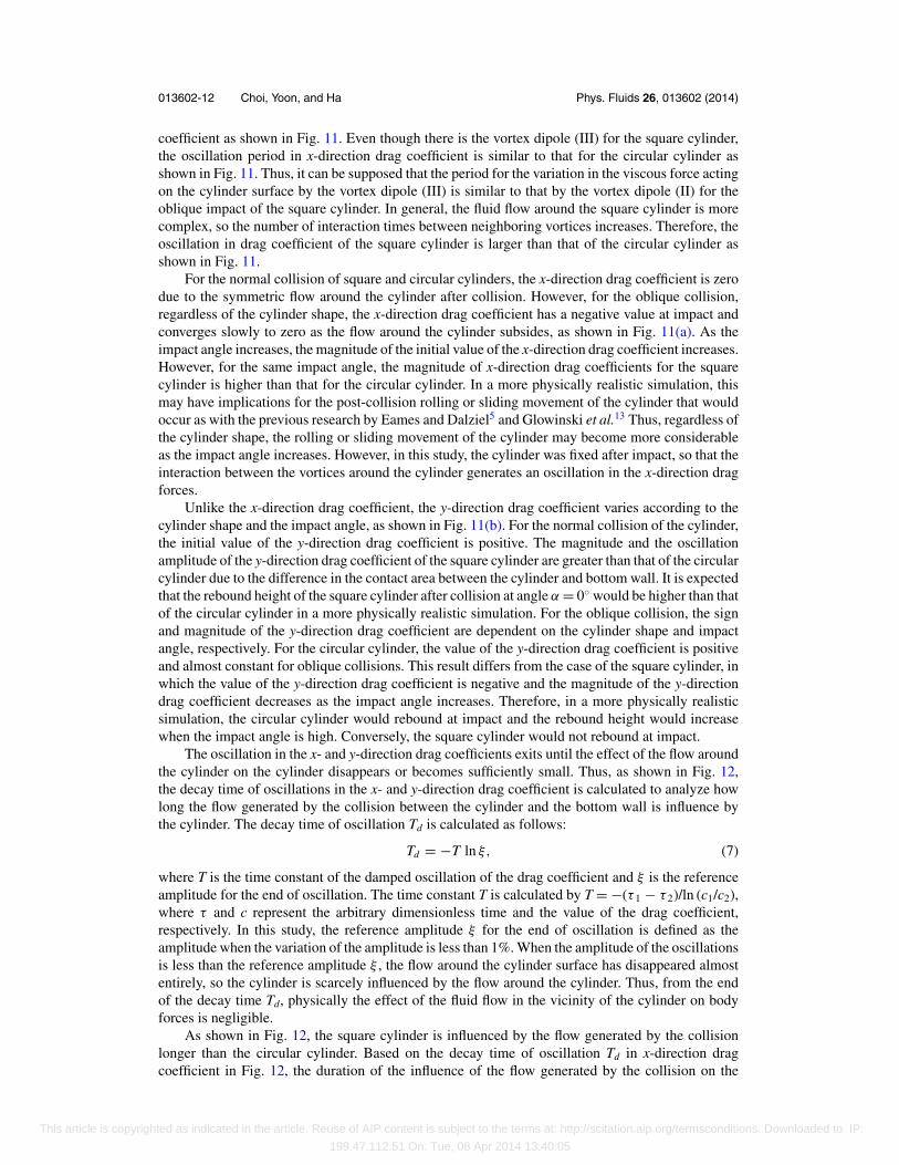
FIG. 12. Decay time of oscillation Td in x- and y-direction drag coefficients for the square and circular cylinders with respectto the impact angle α.
cylinder for the square cylinder is about two times longer than that for the circular cylinder. This isbecause the flow generated around the square cylinder after impact is more complex than that aroundthe circular cylinder as shown in Fig. 9. From the point of view of the x-direction drag coefficient,the duration of the influence of the flow generated by the collision on the body force increases asthe impact angle increase as shown in Fig. 12. In contrast to the x-direction drag coefficient, thereis no oscillation in the y-direction drag coefficient for the circular cylinder impact, so there is noinformation about the y-direction drag coefficient for the circular cylinder in Fig. 12. The duration ofthe oscillations in the y-direction drag coefficient for the square cylinder increases up to α = 21◦ asshown in Fig. 12. When the impact angle α is 21◦, the decay time of the oscillation of the y-directiondrag coefficient for the square cylinder is slightly longer than that of the x-direction one. However,as the impact angle increases, the decay time of the oscillations Td of the y-direction drag coefficientdecreases as shown in Fig. 12.
IV. CONCLUSIONS
The presented study numerically investigated the flow structure around a square cylinderimpacting a wall. We focused on the effects of both the cylinder shape and the impact angle onthe fluid flow and the drag forces on the cylinder at the Reynolds number of 200.
When the square and circular cylinders collided with a wall at Re = 200, there were no three-dimensional instabilities in the flow around the cylinders regardless of the cylinder shape and impactangle.
The dynamics of the vortex tubes after impact were analyzed by the trajectory of the primaryvortex. The x-directional trajectory of the left primary vortex tube of the square cylinder was shorterthan that of the circular cylinder. Conversely, the right primary vortex tube of the square cylinderexhibited a longer x-directional trajectory than that of the circular cylinder. The moving distance ofthe primary vortex tube in the y-direction around the square cylinder after impact was smaller thanthat around the circular cylinder, regardless of the impact angle.
The period of oscillation in drag coefficient was caused by the cyclic variation in viscous forceinduced by the vortex dipole movement and the variation of vortex strength. The x-direction dragcoefficient had the same sign for both square and circular cylinders. However, the magnitude andoscillation amplitude of the drag coefficient for the square cylinder after impact were higher thanthose for the circular cylinder. For the case of the normal collision, the y-direction drag coefficient
This article is copyrighted as indicated in the article. Reuse of AIP content is subject to the terms at: http://scitation.aip.org/termsconditions. Downloaded to IP:
199.47.112.51 On: Tue, 08 Apr 2014 13:40:05
013602-14 Choi, Yoon, and Ha Phys. Fluids 26, 013602 (2014)
for the square cylinder impact had the same sign as that for the circular cylinder impact. However,for the case of oblique collision, the sign of the y-direction drag coefficient was dependent on thecylinder shape; negative for the square cylinder and positive for the circular cylinder. The durationof the influence of the flow generated by the collision on the cylinder is dependent on the cylindershape as well as the impact angle. The square cylinder is influenced by the flow generated by thecollision for a long time compared to the circular cylinder.
ACKNOWLEDGMENTS
This research was supported by Leading Foreign Research Institute Recruitment Programthrough the National Research Foundation of Korea (NRF) funded by the Ministry of Science,ICT & Future Planning (No. 2013044133). This work was supported by the National ResearchFoundation of Korea (NRF) grant funded by the Korea government (MEST) (No. 2011–0030662).Further support of this work was provided by PLSI supercomputing resources of Korea Institute ofScience and Technology Information.
1 W. John, D. N. Fritter, and W. Winklmayr, “Resuspension induced by impacting particles,” J. Aerosol Sci. 22, 723–736(1991).
2 G. Ziskind, M. Fichman, and C. Gutfinger, “Resuspension of particulates from surfaces to turbulent flows – Review andanalysis,” J. Aerosol Sci. 26, 613–644 (1995).
3 T. Leweke, M. C. Thompson, and K. Hourigan, “Instability of the flow around an impacting sphere,” J. Fluid Struct. 22,961–971 (2006).
4 M. C. Thompson, K. Hourigan, A. Cheung, and T. Leweke, “Hydrodynamics of a particle impact on a wall,” Appl. Math.Model. 30, 1356–1369 (2006).
5 I. Eames and S. B. Dalziel, “Dust resuspension by the flow around an impacting sphere,” J. Fluid Mech. 403, 305–328(2000).
6 G. G. Joseph, R. Zenit, M. L. Hunt, and A. M. Rosenwinkel, “Particle-wall collisions in a viscous fluid,” J. Fluid Mech.433, 329–346 (2001).
7 T. Leweke, M. C. Thompson, and K. Hourigan, “Vortex dynamics associated with the collision of a sphere with a wall,”Phys. Fluids 16, L74–L77 (2004).
8 M. C. Thompson, T. Leweke, and K. Hourigan, “Sphere-wall collisions: Vortex dynamics and stability,” J. Fluid Mech.575, 121–148 (2007).
9 T. Leweke, L. Schouveiler, M. C. Thompson, and K. Hourigan, “Unsteady flow around impacting bluff bodies,” J. FluidStruct. 24, 1194–1203 (2008).
10 H. Choi and P. Moin, “Effects of the computational time step on numerical solutions of turbulent flow,” J. Comput. Phys.113, 1–4 (1994).
11 C. Choi, H. S. Yoon, and M. Y. Ha, “Flow and motion characteristics of a freely falling square particle in a channel,”Comput. Fluids 79, 1–12 (2013).
12 J. D. A. Walker, C. R. Smith, A. W. Cerra, and T. L. Doligalski, “The impact of a vortex ring on a wall,” J. Fluid Mech.181, 99–140 (1987).
13 R. Glowinski, T. W. Pan, T. I. Hesla, D. D. Joseph, and J. Periaux, “A fictitious domain approach to the direct numericalsimulation of incompressible viscous flow past moving rigid bodies: Application to particulate flow,” J. Comput. Phys.169, 363–426 (2001).
This article is copyrighted as indicated in the article. Reuse of AIP content is subject to the terms at: http://scitation.aip.org/termsconditions. Downloaded to IP:
199.47.112.51 On: Tue, 08 Apr 2014 13:40:05