flow / pressure control and monitoringemanuals.nordson.com/adhesives/english_manuals/1120351.pdf ·...
TRANSCRIPT

Flow / Pressure Control andMonitoring
Customer Product ManualPart 1120351
Issued 5/12
NORDSON CORPORATION DULUTH, GEORGIA USAwww.nordson.com
This document contains important safety informationBe sure to read and follow all safety information in thisdocument and any other related documentation.

Part 1120351_01 � 2012 Nordson CorporationAll rights reserved
Nordson Corporation welcomes requests for information, comments, and inquiries about its products. General informationabout Nordson can be found on the Internet using the following address: http://www.nordson.com.
Address all correspondence to:
Nordson CorporationAttn: Customer Service11475 Lakefield Drive
Duluth, GA 30097
Notice
This is a Nordson Corporation publication which is protected by copyright. Original copyright date 2012.No�part�of�this�document may be photocopied, reproduced, or translated to another language without the prior written
consent of Nordson�Corporation. The�information�contained in this publication is subject to change without notice.
Trademarks
AccuJet, AeroCharge, Apogee, AquaGuard, Asymtek, Automove, Baitgun, Blue Box, Bowtie, CanWorks, Century, CF, CleanSleeve, CleanSpray, ColorMax,Color‐on‐Demand, Control�Coat, Coolwave, Cross‐Cut, cScan+, Dage, Dispensejet, DispenseMate, DuraBlue, DuraDrum, Durafiber, DuraPail,
Dura‐Screen, Durasystem, Easy�Coat, Easymove Plus, Ecodry, Econo‐Coat, e.DOT, EFD, Emerald, Encore, ESP, e stylized, ETI ‐ stylized, Excel 2000,Fibrijet, Fillmaster, FlexiCoat, Flex‐O‐Coat, Flow Sentry, Fluidmove, FoamMelt, FoamMix, Fulfill, GreenUV, HDLV, Heli‐flow, Horizon, Hot Shot, iControl,
iDry, iFlow, Isocoil, Isocore, Iso‐Flo, iTRAX, Kinetix, LEAN�CELL, Little�Squirt, LogiComm, Magnastatic, March, Maverick, MEG, Meltex, Microcoat,Micromark, Micromedics, MicroSet, Millennium, Mini Squirt, Mountaingate, Nordson, Optimum, Package of Values, Pattern View, PermaFlo, PicoDot,Porous�Coat, PowderGrid, Powderware, Precisecoat, PRIMARC, Printplus, Prism, ProBlue, Prodigy, Pro‐Flo, ProLink, Pro‐Meter, Pro‐Stream, RBX,
Rhino, Saturn, Saturn with rings, Scoreguard, Seal Sentry, Select�Charge, Select�Coat, Select Cure, Signature, Slautterback, Smart‐Coat, Solder Plus,Spectrum, Speed‐Coat, SureBead, Sure Coat, Sure‐Max, Sure Wrap, Tracking�Plus, TRAK, Trends, Tribomatic, TrueBlue, TrueCoat, Ultra, UpTime,u‐TAH, Vantage, VersaBlue, Versa‐Coat, VersaDrum, VersaPail, Versa‐Screen, Versa‐Spray, Watermark, and When you expect more. are registered
trademarks of Nordson Corporation.
Accubar, Active Nozzle, Advanced Plasma Systems, AeroDeck, AeroWash, AltaBlue, AltaSlot, Alta Spray, Artiste, ATS, Auto‐Flo, AutoScan, Axiom, Best Choice, Blue Series, Bravura, CanPro, Champion, Check Mate, ClassicBlue, Classic IX, Clean�Coat, Cobalt, Controlled Fiberization, Control�Weave,
ContourCoat, CPX, cSelect, Cyclo‐Kinetic, DispensLink, Dry Cure, DuraBraid, DuraCoat, DuraPUR, Easy Clean, EasyOn, EasyPW, Eclipse, e.dot+,E‐Nordson, Equalizer, EquiBead, FillEasy, Fill�Sentry, Flow Coat, Fluxplus, Get Green With Blue, G‐Net, G‐Site, IntelliJet, iON, Iso‐Flex, iTrend,
Lacquer Cure, Maxima, Mesa, MicroFin, MicroMax, Mikros, MiniBlue, MiniEdge, Minimeter, Multifill, MultiScan, Myritex, Nano, NexJet, OmniScan, OptiMix,OptiStroke, Partnership+Plus, PatternJet, PatternPro, PCI, Pinnacle, Plasmod, Powder�Pilot, Powder Port, Powercure, Process Sentry, Pulse Spray,
PURBlue, PURJet, Ready Coat, RediCoat, Royal Blue, Select�Series, Sensomatic, Shaftshield, SheetAire, Smart, Smartfil, SolidBlue, Spectral, SpeedKing,Spray Works, Summit, SureFoam, Sure�Mix, SureSeal, Swirl�Coat, TAH, ThruWave, Trade�Plus, Trilogy, Ultra FoamMix, UltraMax, Ultrasaver, Ultrasmart,
Universal, ValueMate, Versa, Vista, Web Cure, YESTECH, and 2�Rings (Design) are�trademarks of Nordson�Corporation.
Designations and trademarks stated in this document may be brands that, when used by third parties for their own purposes, could lead to violation of the owners' rights.
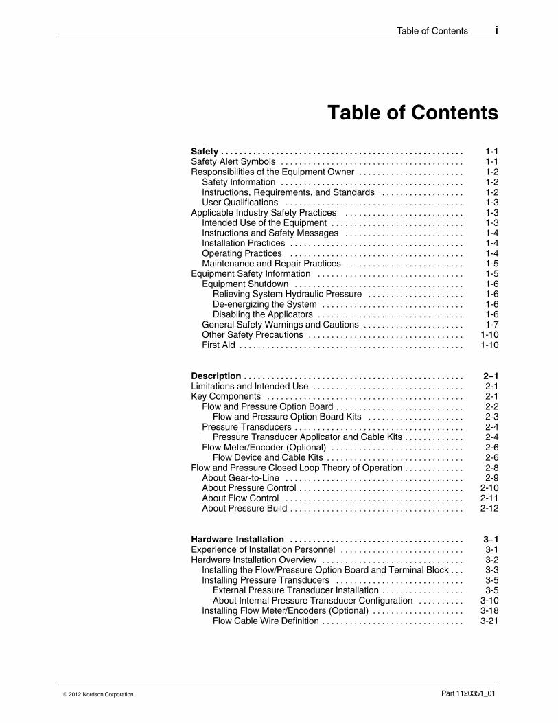
Table of Contents i
Part 1120351_01� 2012 Nordson Corporation
Table of Contents
Safety 1-1. . . . . . . . . . . . . . . . . . . . . . . . . . . . . . . . . . . . . . . . . . . . . . . . . . . . .Safety Alert Symbols 1‐1. . . . . . . . . . . . . . . . . . . . . . . . . . . . . . . . . . . . . . . .Responsibilities of the Equipment Owner 1‐2. . . . . . . . . . . . . . . . . . . . . . .
Safety Information 1‐2. . . . . . . . . . . . . . . . . . . . . . . . . . . . . . . . . . . . . . . .Instructions, Requirements, and Standards 1‐2. . . . . . . . . . . . . . . . . .User Qualifications 1‐3. . . . . . . . . . . . . . . . . . . . . . . . . . . . . . . . . . . . . . .
Applicable Industry Safety Practices 1‐3. . . . . . . . . . . . . . . . . . . . . . . . . .Intended Use of the Equipment 1‐3. . . . . . . . . . . . . . . . . . . . . . . . . . . . .Instructions and Safety Messages 1‐4. . . . . . . . . . . . . . . . . . . . . . . . . .Installation Practices 1‐4. . . . . . . . . . . . . . . . . . . . . . . . . . . . . . . . . . . . . .Operating Practices 1‐4. . . . . . . . . . . . . . . . . . . . . . . . . . . . . . . . . . . . . .Maintenance and Repair Practices 1‐5. . . . . . . . . . . . . . . . . . . . . . . . .
Equipment Safety Information 1‐5. . . . . . . . . . . . . . . . . . . . . . . . . . . . . . . .Equipment Shutdown 1‐6. . . . . . . . . . . . . . . . . . . . . . . . . . . . . . . . . . . . .
Relieving System Hydraulic Pressure 1‐6. . . . . . . . . . . . . . . . . . . . .De‐energizing the System 1‐6. . . . . . . . . . . . . . . . . . . . . . . . . . . . . . .Disabling the Applicators 1‐6. . . . . . . . . . . . . . . . . . . . . . . . . . . . . . . .
General Safety Warnings and Cautions 1‐7. . . . . . . . . . . . . . . . . . . . . .Other Safety Precautions 1‐10. . . . . . . . . . . . . . . . . . . . . . . . . . . . . . . . . .First Aid 1‐10. . . . . . . . . . . . . . . . . . . . . . . . . . . . . . . . . . . . . . . . . . . . . . . . .
Description 2−1. . . . . . . . . . . . . . . . . . . . . . . . . . . . . . . . . . . . . . . . . . . . . . . .Limitations and Intended Use 2-1. . . . . . . . . . . . . . . . . . . . . . . . . . . . . . . . .Key Components 2-1. . . . . . . . . . . . . . . . . . . . . . . . . . . . . . . . . . . . . . . . . . .
Flow and Pressure Option Board 2-2. . . . . . . . . . . . . . . . . . . . . . . . . . . .Flow and Pressure Option Board Kits 2-3. . . . . . . . . . . . . . . . . . . . .
Pressure Transducers 2-4. . . . . . . . . . . . . . . . . . . . . . . . . . . . . . . . . . . . .Pressure Transducer Applicator and Cable Kits 2-4. . . . . . . . . . . . .
Flow Meter/Encoder (Optional) 2-6. . . . . . . . . . . . . . . . . . . . . . . . . . . . .Flow Device and Cable Kits 2-6. . . . . . . . . . . . . . . . . . . . . . . . . . . . . .
Flow and Pressure Closed Loop Theory of Operation 2-8. . . . . . . . . . . . .About Gear-to-Line 2-9. . . . . . . . . . . . . . . . . . . . . . . . . . . . . . . . . . . . . . .About Pressure Control 2-10. . . . . . . . . . . . . . . . . . . . . . . . . . . . . . . . . . . .About Flow Control 2-11. . . . . . . . . . . . . . . . . . . . . . . . . . . . . . . . . . . . . . .About Pressure Build 2-12. . . . . . . . . . . . . . . . . . . . . . . . . . . . . . . . . . . . . .
Hardware Installation 3−1. . . . . . . . . . . . . . . . . . . . . . . . . . . . . . . . . . . . . .Experience of Installation Personnel 3-1. . . . . . . . . . . . . . . . . . . . . . . . . . .Hardware Installation Overview 3-2. . . . . . . . . . . . . . . . . . . . . . . . . . . . . . .
Installing the Flow/Pressure Option Board and Terminal Block 3-3. . .Installing Pressure Transducers 3-5. . . . . . . . . . . . . . . . . . . . . . . . . . . .
External Pressure Transducer Installation 3-5. . . . . . . . . . . . . . . . . .About Internal Pressure Transducer Configuration 3-10. . . . . . . . . .
Installing Flow Meter/Encoders (Optional) 3-18. . . . . . . . . . . . . . . . . . . .Flow Cable Wire Definition 3-21. . . . . . . . . . . . . . . . . . . . . . . . . . . . . . .

Table of Contentsii
Part 1120351_01 � 2012 Nordson Corporation
Operation 4−1. . . . . . . . . . . . . . . . . . . . . . . . . . . . . . . . . . . . . . . . . . . . . . . . .Overview 4-1. . . . . . . . . . . . . . . . . . . . . . . . . . . . . . . . . . . . . . . . . . . . . . . . . .
What's Next? 4-1. . . . . . . . . . . . . . . . . . . . . . . . . . . . . . . . . . . . . . . . . .Changing Pump Operation Modes 4-2. . . . . . . . . . . . . . . . . . . . . . . . . .Configuring and Modifying Pressure Control and Monitor 4-3. . . . . . .Configuring and Modifying Flow Control and Monitor 4-6. . . . . . . . . . .Viewing Total Adhesive Used 4-10. . . . . . . . . . . . . . . . . . . . . . . . . . . . . . .Configuring Gear-to-Line with Pressure/Flow Monitoring 4-11. . . . . . . .About Testing and Fine-Tuning Configurations 4-16. . . . . . . . . . . . . . . .
More About PIDs 4-16. . . . . . . . . . . . . . . . . . . . . . . . . . . . . . . . . . . . . . .Fine-Tuning Pressure Control 4-18. . . . . . . . . . . . . . . . . . . . . . . . . . . . . .Fine-Tuning Flow Control 4-21. . . . . . . . . . . . . . . . . . . . . . . . . . . . . . . . . .Configuring Channel Alert/Fault Alarms 4-24. . . . . . . . . . . . . . . . . . . . . .Monitoring and Data Logging 4-26. . . . . . . . . . . . . . . . . . . . . . . . . . . . . . .Viewing Pump and Channel Settings 4-28. . . . . . . . . . . . . . . . . . . . . . . .Accessing the SD Card 4-29. . . . . . . . . . . . . . . . . . . . . . . . . . . . . . . . . . . .Stop Using / Disable a Channel 4-30. . . . . . . . . . . . . . . . . . . . . . . . . . . . .
Default Flow and Pressure Settings and Ranges 4-31. . . . . . . . . . . . . . . . .Flow Global Settings 4-31. . . . . . . . . . . . . . . . . . . . . . . . . . . . . . . . . . . .Flow Settings 4-32. . . . . . . . . . . . . . . . . . . . . . . . . . . . . . . . . . . . . . . . . .Pressure Settings 4-34. . . . . . . . . . . . . . . . . . . . . . . . . . . . . . . . . . . . . .
Maintenance 5-1. . . . . . . . . . . . . . . . . . . . . . . . . . . . . . . . . . . . . . . . . . . . . .Relieving Pressure 5‐2. . . . . . . . . . . . . . . . . . . . . . . . . . . . . . . . . . . . . . . . . .Maintenance Table 5‐2. . . . . . . . . . . . . . . . . . . . . . . . . . . . . . . . . . . . . . . . . .Electrical and Pneumatic Connecting Lines 5‐3. . . . . . . . . . . . . . . . . . . . .
Visual Inspection for External Damage 5‐3. . . . . . . . . . . . . . . . . . . . . . .Flow‐Splitter 5‐3. . . . . . . . . . . . . . . . . . . . . . . . . . . . . . . . . . . . . . . . . . . . . . .
Checking for Leakage 5‐3. . . . . . . . . . . . . . . . . . . . . . . . . . . . . . . . . . . . .Replacing Shaft Seal 5‐3. . . . . . . . . . . . . . . . . . . . . . . . . . . . . . . . . . .
Tightening Fixing Screws 5‐4. . . . . . . . . . . . . . . . . . . . . . . . . . . . . . . . . .Flow Applicator 5‐5. . . . . . . . . . . . . . . . . . . . . . . . . . . . . . . . . . . . . . . . . . . . .
External Cleaning 5‐5. . . . . . . . . . . . . . . . . . . . . . . . . . . . . . . . . . . . . . . . .Changing Material 5‐5. . . . . . . . . . . . . . . . . . . . . . . . . . . . . . . . . . . . . . . .Cleaning Filter Cartridge 5‐5. . . . . . . . . . . . . . . . . . . . . . . . . . . . . . . . . . .
Removing Filter Cartridge 5‐6. . . . . . . . . . . . . . . . . . . . . . . . . . . . . . .Replacing Filter Screen 5‐6. . . . . . . . . . . . . . . . . . . . . . . . . . . . . . . . .Installing Filter Cartridge 5‐7. . . . . . . . . . . . . . . . . . . . . . . . . . . . . . . . .
Flow Divider 5‐8. . . . . . . . . . . . . . . . . . . . . . . . . . . . . . . . . . . . . . . . . . . . . . . .Purging with Cleaning Agent 5‐8. . . . . . . . . . . . . . . . . . . . . . . . . . . . . . .Cleaning Complete Flow Divider 5‐8. . . . . . . . . . . . . . . . . . . . . . . . . . . .Forcibly Actuating Safety Valve 5‐8. . . . . . . . . . . . . . . . . . . . . . . . . . . . .
Flow General and Technical Data 5‐9. . . . . . . . . . . . . . . . . . . . . . . . . . . . .Temperatures 5‐10. . . . . . . . . . . . . . . . . . . . . . . . . . . . . . . . . . . . . . . . . . . .Air pressure 5‐10. . . . . . . . . . . . . . . . . . . . . . . . . . . . . . . . . . . . . . . . . . . . .Electrical Data 5‐11. . . . . . . . . . . . . . . . . . . . . . . . . . . . . . . . . . . . . . . . . . .Dimensions and Weights 5‐11. . . . . . . . . . . . . . . . . . . . . . . . . . . . . . . . . .
Processing Materials 5‐11. . . . . . . . . . . . . . . . . . . . . . . . . . . . . . . . . . . . . . . .Torques 5‐11. . . . . . . . . . . . . . . . . . . . . . . . . . . . . . . . . . . . . . . . . . . . . . . . . . .Pressure Transducer Maintenance 5‐12. . . . . . . . . . . . . . . . . . . . . . . . . . . .

Table of Contents iii
Part 1120351_01� 2012 Nordson Corporation
Troubleshooting 6-1. . . . . . . . . . . . . . . . . . . . . . . . . . . . . . . . . . . . . . . . . . .Flow and Pressure Alerts/Faults Pop-up Messages 6‐2. . . . . . . . . . . .Troubleshooting Flow Rate Issues 6‐3. . . . . . . . . . . . . . . . . . . . . . . . . .
Parts 7-1. . . . . . . . . . . . . . . . . . . . . . . . . . . . . . . . . . . . . . . . . . . . . . . . . . . . . .Using the Illustrated Parts Lists 7‐1. . . . . . . . . . . . . . . . . . . . . . . . . . . . . . .
Flow Encoder 7‐2. . . . . . . . . . . . . . . . . . . . . . . . . . . . . . . . . . . . . . . . . . . .Flow Meter 7‐4. . . . . . . . . . . . . . . . . . . . . . . . . . . . . . . . . . . . . . . . . . . . . .Flow Cable 7‐6. . . . . . . . . . . . . . . . . . . . . . . . . . . . . . . . . . . . . . . . . . . . . .Pressure Build Control Parts 7‐7. . . . . . . . . . . . . . . . . . . . . . . . . . . . . . .External Pressure Transducer Parts 7‐9. . . . . . . . . . . . . . . . . . . . . . . . .External Pressure Cable (4-20mA) 7‐10. . . . . . . . . . . . . . . . . . . . . . . . . .External Pressure Cable (0-10V) 7‐11. . . . . . . . . . . . . . . . . . . . . . . . . . . .Recommended Spare Parts 7‐12. . . . . . . . . . . . . . . . . . . . . . . . . . . . . . . .

Safety 1-1
� 2012 Nordson Corporation Issued 10-11
Section 1Safety
Read this section before using the equipment. This section containsrecommendations and practices applicable to the safe installation, operation,and maintenance (hereafter referred to as “use”) of the product described inthis document (hereafter referred to as “equipment”). Additional safetyinformation, in the form of task‐specific safety alert messages, appears asappropriate throughout this document.
WARNING! Failure to follow the safety messages, recommendations, andhazard avoidance procedures provided in this document can result inpersonal injury, including death, or damage to equipment or property.
Safety Alert SymbolsThe following safety alert symbol and signal words are used throughout thisdocument to alert the reader to personal safety hazards or to identifyconditions that may result in damage to equipment or property. Comply withall safety information that follows the signal word.
WARNING! Indicates a potentially hazardous situation that, if not avoided,can result in serious personal injury, including death.
CAUTION! Indicates a potentially hazardous situation that, if not avoided,can result in minor or moderate personal injury.
CAUTION! (Used without the safety alert symbol) Indicates a potentiallyhazardous situation that, if not avoided, can result in damage to equipment orproperty.

Safety1-2
� 2012 Nordson CorporationIssued 10−11
Responsibilities of the Equipment Owner Equipment owners are responsible for managing safety information, ensuringthat all instructions and regulatory requirements for use of the equipment aremet, and for qualifying all potential users.
Safety Information � Research and evaluate safety information from all applicable sources,
including the owner‐specific safety policy, best industry practices,governing regulations, material manufacturer's product information, andthis document.
� Make safety information available to equipment users in accordance with
governing regulations. Contact the authority having jurisdiction forinformation.
� Maintain safety information, including the safety labels affixed to the
equipment, in readable condition.
Instructions, Requirements, and Standards � Ensure that the equipment is used in accordance with the information
provided in this document, governing codes and regulations, and bestindustry practices.
� If applicable, receive approval from your facility's engineering or safety
department, or other similar function within your organization, beforeinstalling or operating the equipment for the first time.
� Provide appropriate emergency and first aid equipment.
� Conduct safety inspections to ensure required practices are being
followed.
� Re‐evaluate safety practices and procedures whenever changes are
made to the process or equipment.

Safety 1-3
� 2012 Nordson Corporation Issued 10-11
User Qualifications
Equipment owners are responsible for ensuring that users:
� receive safety training appropriate to their job function as directed by
governing regulations and best industry practices
� are familiar with the equipment owner's safety and accident
prevention policies and procedures
� receive equipment‐ and task‐specific training from another qualified
individual
NOTE: Nordson can provide equipment‐specific installation,operation, and maintenance training. Contact your Nordsonrepresentative for information
� possess industry‐ and trade‐specific skills and a level of experience
appropriate to their job function
� are physically capable of performing their job function and are not
under the influence of any substance that degrades their mentalcapacity or physical capabilities
Applicable Industry Safety Practices The following safety practices apply to the use of the equipment in themanner described in this document. The information provided here is notmeant to include all possible safety practices, but represents the best safetypractices for equipment of similar hazard potential used in similar industries.
Intended Use of the Equipment � Use the equipment only for the purposes described and within the limits
specified in this document.
� Do not modify the equipment.
� Do not use incompatible materials or unapproved auxiliary devices.
Contact your Nordson representative if you have any questions onmaterial compatibility or the use of non‐standard auxiliary devices.
Safety1-4
� 2012 Nordson CorporationIssued 10−11
Instructions and Safety Messages � Read and follow the instructions provided in this document and other
referenced documents.
� Familiarize yourself with the location and meaning of the safety warning
labels and tags affixed to the equipment. Refer to Safety Labels and Tagsat the end of this section.
� If you are unsure of how to use the equipment, contact your Nordson
representative for assistance.
Installation Practices � Install the equipment in accordance with the instructions provided in this
document and in the documentation provided with auxiliary devices.
� Ensure that the equipment is rated for the environment in which it will be
used. This equipment has not been certified for compliance with theATEX directive nor as nonincendive and should not be installed inpotentially explosive environments.
� Ensure that the processing characteristics of the material will not create a
hazardous environment. Refer to the Material Safety Data Sheet (MSDS)for the material.
� If the required installation configuration does not match the installation
instructions, contact your Nordson representative for assistance.
� Position the equipment for safe operation. Observe the requirements for
clearance between the equipment and other objects.
� Install lockable power disconnects to isolate the equipment and all
independently powered auxiliary devices from their power sources.
� Properly ground all equipment. Contact your local building code
enforcement agency for specific requirements.
� Ensure that fuses of the correct type and rating are installed in fused
equipment.
� Contact the authority having jurisdiction to determine the requirement for
installation permits or inspections.
Operating Practices � Familiarize yourself with the location and operation of all safety devices
and indicators.
� Confirm that the equipment, including all safety devices (guards,
interlocks, etc.), is in good working order and that the requiredenvironmental conditions exist.
� Use the personal protective equipment (PPE) specified for each task.
Refer to Equipment Safety Information or the material manufacturer'sinstructions and MSDS for PPE requirements.
� Do not use equipment that is malfunctioning or shows signs of a potential
malfunction.

Safety 1-5
� 2012 Nordson Corporation Issued 10-11
Maintenance and Repair Practices � Allow only personnel with appropriate training and experience to operate
or service the equipment.
� Perform scheduled maintenance activities at the intervals described in
this document.
� Relieve system hydraulic and pneumatic pressure before servicing the
equipment.
� De‐energize the equipment and all auxiliary devices before servicing the
equipment.
� Use only new Nordson‐authorized refurbished or replacement parts.
� Read and comply with the manufacturer's instructions and the MSDS
supplied with equipment cleaning compounds.
NOTE: MSDSs for cleaning compounds that are sold by Nordson areavailable at www.nordson.com or by calling your Nordson representative.
� Confirm the correct operation of all safety devices before placing the
equipment back into operation.
� Dispose of waste cleaning compounds and residual process materials
according to governing regulations. Refer to the applicable MSDS orcontact the authority having jurisdiction for information.
� Keep equipment safety warning labels clean. Replace worn or damaged
labels.
Equipment Safety Information This equipment safety information is applicable to the following types ofNordson equipment:
� hot melt and cold adhesive application equipment and all related
accessories
� pattern controllers, timers, detection and verification systems, and all
other optional process control devices

Safety1-6
� 2012 Nordson CorporationIssued 10−11
Equipment Shutdown
To safely complete many of the procedures described in this document, theequipment must first be shut down. The level of shut down required varies bythe type of equipment in use and the procedure being completed. If required, shut down instructions are specified at the start of the procedure.
Relieving System Hydraulic Pressure
Completely relieve system hydraulic pressure before breaking any hydraulicconnection or seal. Refer to the melter‐specific product manual forinstructions on relieving system hydraulic pressure.
De‐energizing the System
Isolate the system (melter, hoses, applicators, and optional devices) from allpower sources before accessing any unprotected high‐voltage wiring orconnection point.
1. Turn off the equipment and all auxiliary devices connected to theequipment (system).
2. To prevent the equipment from being accidentally energized, lock andtag the disconnect switch(es) or circuit breaker(s) that provide inputelectrical power to the equipment and optional devices.
NOTE: Government regulations and industry standards dictate specificrequirements for the isolation of hazardous energy sources. Refer to theappropriate regulation or standard.
Disabling the Applicators
NOTE: Adhesive dispensing applicators are referred to as “guns” in someprevious publications.
All electrical or mechanical devices that provide an activation signal to theapplicators, applicator solenoid valve(s), or the melter pump must bedisabled before work can be performed on or around an applicator that isconnected to a pressurized system.
1. Turn off or disconnect the applicator triggering device (pattern controller,timer, PLC, etc.).
2. Disconnect the input signal wiring to the applicator solenoid valve(s).
3. Reduce the air pressure to the applicator solenoid valve(s) to zero; thenrelieve the residual air pressure between the regulator and the applicator.

Safety 1-7
� 2012 Nordson Corporation Issued 10-11
General Safety Warnings and Cautions
Table 1‐1 contains the general safety warnings and cautions that apply toNordson hot melt and cold adhesive equipment. Review the table andcarefully read all of the warnings or cautions that apply to the type ofequipment described in this manual.
Equipment types are designated in Table 1‐1 as follows:
HM = Hot melt (melters, hoses, applicators, etc.)
PC = Process control
CA = Cold adhesive (dispensing pumps, pressurized container, andapplicators)
Table 1‐1General Safety Warnings and Cautions
EquipmentType Warning or Caution
HM
WARNING! Hazardous vapors! Before processing any polyurethanereactive (PUR) hot melt or solvent‐based material through a compatibleNordson melter, read and comply with the material's MSDS. Ensurethat the material's processing temperature and flashpoints will not beexceeded and that all requirements for safe handling, ventilation, firstaid, and personal protective equipment are met. Failure to comply withMSDS requirements can cause personal injury, including death.
HM
WARNING! Reactive material! Never clean any aluminum componentor flush Nordson equipment with halogenated hydrocarbon fluids.Nordson melters and applicators contain aluminum components thatmay react violently with halogenated hydrocarbons. The use ofhalogenated hydrocarbon compounds in Nordson equipment cancause personal injury, including death.
HM, CAWARNING! System pressurized! Relieve system hydraulic pressurebefore breaking any hydraulic connection or seal. Failure to relieve thesystem hydraulic pressure can result in the uncontrolled release of hotmelt or cold adhesive, causing personal injury.
Continued...

Safety1-8
� 2012 Nordson CorporationIssued 10−11
Table 1‐1General Safety Warnings and Cautions (contd)
EquipmentType Warning or Caution
HMWARNING! Molten material! Wear eye or face protection, clothing thatprotects exposed skin, and heat‐protective gloves when servicingequipment that contains molten hot melt. Even when solidified, hot meltcan still cause burns. Failure to wear appropriate personal protectiveequipment can result in personal injury.
HM, PC
WARNING! Equipment starts automatically! Remote triggering devicesare used to control automatic hot melt applicators. Before working onor near an operating applicator, disable the applicator's triggeringdevice and remove the air supply to the applicator's solenoid valve(s).Failure to disable the applicator's triggering device and remove thesupply of air to the solenoid valve(s) can result in personal injury.
HM, CA, PC
WARNING! Risk of electrocution! Even when switched off andelectrically isolated at the disconnect switch or circuit breaker, theequipment may still be connected to energized auxiliary devices.De‐energize and electrically isolate all auxiliary devices beforeservicing the equipment. Failure to properly isolate electrical power toauxiliary equipment before servicing the equipment can result inpersonal injury, including death.
HM, CA, PC
WARNING! Risk of fire or explosion! Nordson adhesive equipment isnot rated for use in explosive environments and has not been cerfifiedfor the ATEX directive or as nonincendive. In addition, this equipmentshould not be used with solvent‐based adhesives that can create anexplosive atmosphere when processed. Refer to the MSDS for theadhesive to determine its processing characteristics and limitations.The use of incompatible solvent‐based adhesives or the improperprocessing of solvent‐based adhesives can result in personal injury,including death.
HM, CA, PCWARNING! Allow only personnel with appropriate training andexperience to operate or service the equipment. The use of untrainedor inexperienced personnel to operate or service the equipment canresult in injury, including death, to themselves and others and candamage to the equipment.

Safety 1-9
� 2012 Nordson Corporation Issued 10-11
Warning or CautionEquipment
Type
HMCAUTION! Hot surfaces! Avoid contact with the hot metal surfaces ofapplicators, hoses, and certain components of the melter. If contactcan not be avoided, wear heat‐protective gloves and clothing whenworking around heated equipment. Failure to avoid contact with hotmetal surfaces can result in personal injury.
HM
CAUTION! Some Nordson melters are specifically designed toprocess polyurethane reactive (PUR) hot melt. Attempting to processPUR in equipment not specifically designed for this purpose candamage the equipment and cause premature reaction of the hot melt. Ifyou are unsure of the equipment's ability to process PUR, contact yourNordson representative for assistance.
HM, CA
CAUTION! Before using any cleaning or flushing compound on or inthe equipment, read and comply with the manufacturer's instructionsand the MSDS supplied with the compound. Some cleaningcompounds can react unpredictably with hot melt or cold adhesive,resulting in damage to the equipment.
HM
CAUTION! Nordson hot melt equipment is factory tested with NordsonType R fluid that contains polyester adipate plasticizer. Certain hot meltmaterials can react with Type R fluid and form a solid gum that canclog the equipment. Before using the equipment, confirm that the hotmelt is compatible with Type R fluid.

Safety1-10
� 2012 Nordson CorporationIssued 10−11
Other Safety Precautions � Do not use an open flame to heat hot melt system components.
� Check high pressure hoses daily for signs of excessive wear, damage, or
leaks.
� Never point a dispensing handgun at yourself or others.
� Suspend dispensing handguns by their proper suspension point.
First Aid
If molten hot melt comes in contact with your skin:
1. Do NOT attempt to remove the molten hot melt from your skin.
2. Immediately soak the affected area in clean, cold water until the hot melthas cooled.
3. Do NOT attempt to remove the solidified hot melt from your skin.
4. In case of severe burns, treat for shock.
5. Seek expert medical attention immediately. Give the MSDS for the hotmelt to the medical personnel providing treatment.

Description 2−1
Part 1120351_01� 2012 Nordson Corporation
Section 2
Description
The Flow and Pressure Option Board mounts on top of an existing MotorControl Board and expands the available pump operation modes to:
� Flow Control and Monitor - Controls the accurate flow rate of adhesive
dispensing that is based on inline measurements of consumption,addon weights, and application pressure proportional to the linespeed.
� Pressure Control and Monitor - Controls the delivery of consistent
adhesive output by varying pump speed to control system pressureproportional to the line speed.
� Gear-to-Line with optional Flow and/or Pressure Monitoring - View
only flow rates and/or pressure information proportional to the line speed.
NOTE: Flow and Pressure control and monitoring is not available for Manualpump operation.
Limitations and Intended UseFlow and Pressure Control/Monitor board is specifically designed to be used:
� With compatible equipment manufactured by Nordson Corporation
� In non-explosive environments
The Flow and Pressure Control/Monitor board is virtually complete, but isintended to be incorporated into machinery and configured by an integrator.The equipment must not be placed into use in a member state of theEuropean Union until the parent machinery or assemblies have beendeclared by the integrator to be in conformity with the applicable directivesof the European Commission.
Key ComponentsThe primary components are:
� The Flow and Pressure Option Board
� An internal or external pressure transducer
� Flow meter and encoder (optional)
� Remote Visual System (RVS) Light Tower (optional)

Description2−2
Part 1120351_01 � 2012 Nordson Corporation
Flow and Pressure Option Board
The Flow and Pressure Option Board mounts on top of an existing MotorControl Board, expanding the pump operation mode and options.
1
2
Figure 2‐1 The Flow and Pressure Option Board
1. Motor Control board 2. Flow and Pressure Optionboard
The following lists the pump operation mode and options:
� You can install one Flow and Pressure Option Board per Motor Control
Board. Maximum is two per melter.
� Similar to the Motor Control Board, one Flow and Pressure Option Board
controls two (2) pumps.
� When properly installed and when the melter is switched on, the melter
automatically detects the Flow and Pressure Option Board, as well as thefollowing:
‐ which pumps will have the additional pump operation modes and
options
‐ the type of Flow and Pressure Option Board
� There are two types of Flow and Pressure Option Boards:
Monitor Only - Allows you to only monitor and log pump pressureand/or flow rates.
Control and Monitor - Allows a pump to run at a variable speed tomaintain the desired pressure or flow rate based on set point valuesand line speed. You can also monitor and log pump pressure and/orflow rates as well.

Description 2−3
Part 1120351_01� 2012 Nordson Corporation
� You can combine different Flow and Pressure Option Board types within
the melter.
� Table 2‐1 details the additional pump modes and options based on the
type of installed Flow and Pressure Option Board.
Table 2‐1 Available Pump Modes and Options Based on Type of Installed Flow and Pressure Board
Flow and Pressure Option Board Type
Available Pump Modes Optional
Control and Monitor
Flow Control and Monitoring withPressure Build
� Pressure Monitoring
� Alert and Fault Alarms
Pressure Control and Monitoring � Flow Monitoring
� Pressure Build
� Alert and Fault Alarms
Gear-to-Line � Flow Monitoring
� Pressure Monitoring
� Alert and Fault Alarms
Manual None
Monitor Only
Gear-to-Line � Flow Monitoring
� Pressure Monitoring
� Alert and Fault Alarms
Manual None
Flow and Pressure Option Board Kits
Table 2‐2 Flow and Pressure Option Board Kits for Pumps 1 & 2 or Pumps 3 & 4
Item Description Kit PartNumber
PCA Board Flow/Pressure Option Board (Control) for pumps 1 & 2 or pumps 3 & 4 7403137
PCA, Pressure /Flow (Control)
Ribbon Cable, Assembly, 34 POS, 50 in.
Board, breakout, TB, 34POS, screw
SCR, PAN, SLT, M3X6, ZN
Washer, LK, M, INT, M3, STL, ZN
PCA Board Flow/Pressure Option Board (Monitor Only) for pumps 1 & 2 or pumps 3 & 4 7403138
PCA, Pressure /Flow (Monitor Only)
Ribbon Cable, Assembly, 34 POS, 50 in.
Cable Sensor, 6 PIN, E-Panel, M1/2, Touch
SCR, PAN, SLT, M3X6, ZN
Washer, LK, M, INT, M3, STL, ZN

Description2−4
Part 1120351_01 � 2012 Nordson Corporation
Pressure Transducers
Pressure transducers can be installed either inside the melter itself andconnected to the output manifold port, or externally installed and connecteddirectly to the applicator itself.
Figure 2‐2 Pressure Transducer
You can install up to four pressure transducers per pump.
NOTE: You must have at least one internal or external pressure transducerinstalled and calibrated on a pump for either Flow or Pressure control and/ormonitoring.
Pressure Transducer Applicator and Cable Kits
Table 2‐3 Pressure Transducer Kits
Item Description Kit PartNumber
PressureTransducer
KIT,TRANSDUCER,APPLICATOR,4-20MA 7403139
Transducer, Melt Pressure, 4-20mA
Adapter, with O-Ring, Trans, M16X1.5, L=30
Adapter, with O-Ring, Trans, M16X1.5, L=40
Bag, Poly, Kits, Rolls, 3 ½ x 5 ½
PressureTransducer
KIT,TANSDUCER,APPLICATOR,0-10VDC 7403140
Transducer, Melt Pressure, 4-20mA
Adapter, with O-Ring, Trans, M16X1.5, L=30
Adapter, with O-Ring, Trans, M16X1.5, L=40
Bag, Poly, Kits, Rolls, 3 ½ x 5 ½

Description 2−5
Part 1120351_01� 2012 Nordson Corporation
Table 2‐4 Pressure Transducer Cable 0-10 VDC Kits
Item Description Kit PartNumber
PressureTransducer
Cable
KIT,CABLE,0-10V,16FT,PRESSURE 7403141
KIT,CABLE,0-10V,24FT,PRESSURE 7403142
KIT,CABLE,0-10V,30FT,PRESSURE 7403143
Table 2‐5 Pressure Transducer Cable 4-20 mA Kits
Item Description Kit PartNumber
PressureTransducer
Cable
KIT,CABLE,4-20mA,16FT,PRESSURE 7403154
KIT,CABLE,4-20mA,24FT,PRESSURE 7403155
KIT,CABLE,4-20mA,30FT,PRESSURE 7403156

Description2−6
Part 1120351_01 � 2012 Nordson Corporation
Flow Meter/Encoder (Optional)
The flow meter and encoder should be installed as close to the applicator aspossible.
NOTE: Although not required for Flow Monitoring, Flow Control does requirea pressure transducer installed and calibrated for Pressure Build.
1
2
Figure 2-3 Flow meter and encoder
1. Flow Meter 2. Flow Encoder
Flow Device and Cable Kits
Table 2‐6 Flow T and M Style Kits
Item Description Kit PartNumber
Flow Meterand Encoder
KIT,TRUFLOW,T-STYLE,12MM,TRUEFLOW,MELTER 7403146
Flow Meter Assembly, T-Style, Flow
Der, Assembly, Direct MTG, TruFLow
KIT,TRUFLOW,M-STYLE,12MM,TRUEFLOW,MELTER 7403147
Flow Meter Assembly, T-Style, Flow
Der, Assembly, Direct MTG, TruFLow
Description 2−7
Part 1120351_01� 2012 Nordson Corporation
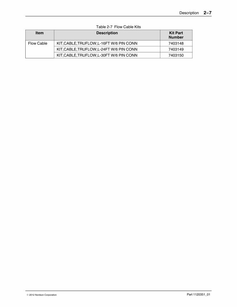
Table 2‐7 Flow Cable Kits
Item Description Kit PartNumber
Flow Cable KIT,CABLE,TRUFLOW,L-16FT W/6 PIN CONN 7403148
KIT,CABLE,TRUFLOW,L-24FT W/6 PIN CONN 7403149
KIT,CABLE,TRUFLOW,L-30FT W/6 PIN CONN 7403150

Description2−8
Part 1120351_01 � 2012 Nordson Corporation
Flow and Pressure Closed Loop Theory ofOperation
The following shows the work flow for both Flow Control and PressureControl.
1.Receive line speed signal,and compute desired flowor pressure value.
2.3. Software compares
desired set point withactual value.Adjusts pump speed to
reduce flow or pressureerrors.

Description 2−9
Part 1120351_01� 2012 Nordson Corporation
About Gear-to-Line
Gear-to-Line uses a single set point to control the pump.
NOTE: You can enter a minimum value on the pump speed to maintain aminimum pump speed, regardless of line speed.
Figure 2‐4 indicates the following:
� At 80% maximum line speed, the pump set point RPM speed is 60 RPM.
� A minimum pump speed of 15 RPM was used.
% Line Speed
0% 20% 40% 60% 80% 100%
Mo
tor
Sp
ee
d (
RP
M)
0
10
20
30
40
50
60
70
80%, 60 RPM
Figure 2‐4 Gear-to-Line, single-point on a curve

Description2−10
Part 1120351_01 � 2012 Nordson Corporation
About Pressure Control
Pressure Control uses two set points to control the pump.
NOTE: If you want a constant pressure, then enter the same pressure forboth set points.
Figure 2‐5 indicates the following:
� At 80% maximum line speed, the desired pressure is 600 PSI.
� At 20% minimum line speed, the desired pressure is 300 PSI.
% Line Speed
0% 20% 40% 60% 80% 100%
Pre
ss
ure
(P
SI)
0
100
200
300
400
500
600
700
20%, 300 PSI
80%, 600 PSI
Figure 2‐5 Pressure Control, double-point on a curve
Description 2−11
Part 1120351_01� 2012 Nordson Corporation
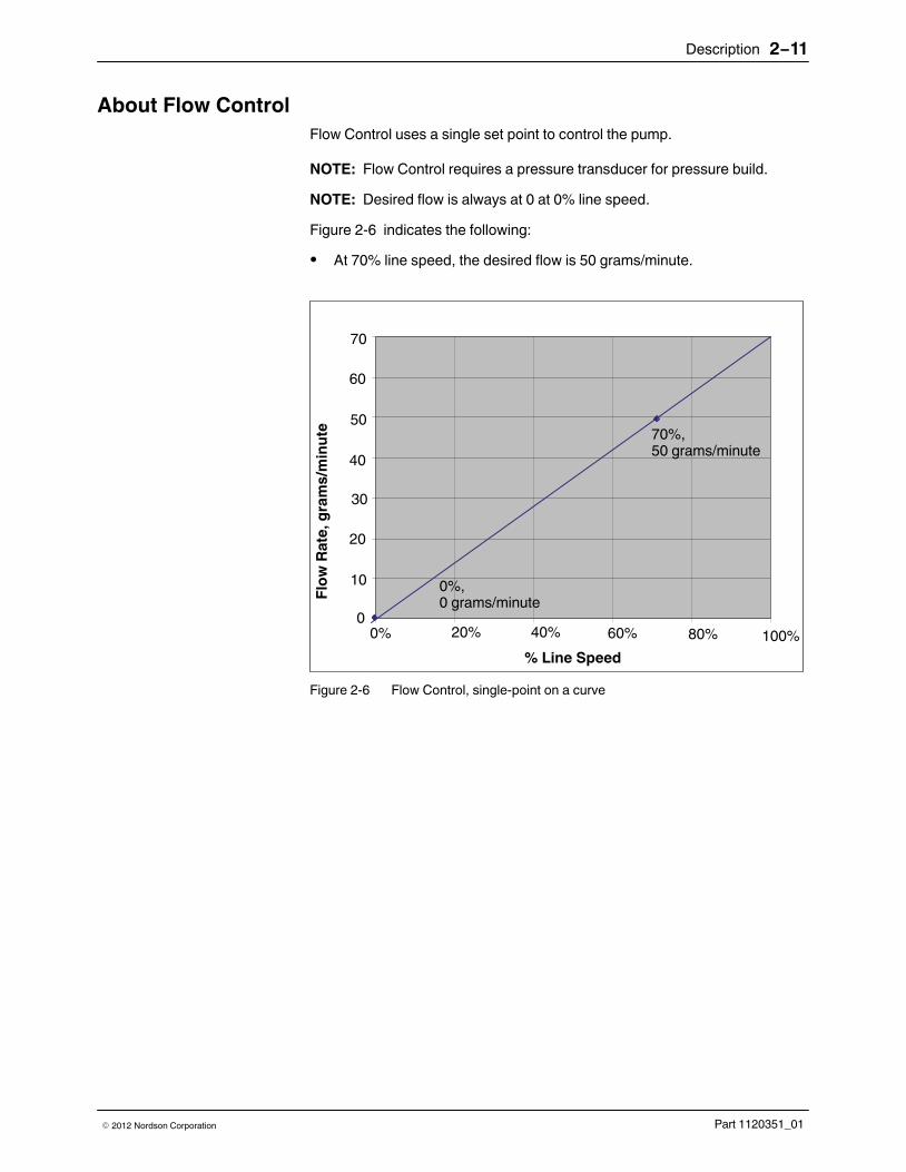
About Flow Control
Flow Control uses a single set point to control the pump.
NOTE: Flow Control requires a pressure transducer for pressure build.
NOTE: Desired flow is always at 0 at 0% line speed.
Figure 2‐6 indicates the following:
� At 70% line speed, the desired flow is 50 grams/minute.
% Line Speed
0% 20% 40% 60% 80% 100%
Flo
w R
ate
, g
ram
s/m
inu
te
0
10
20
30
40
50
60
70
70%,50 grams/minute
0%, 0 grams/minute
Figure 2‐6 Flow Control, single-point on a curve

Description2−12
Part 1120351_01 � 2012 Nordson Corporation
About Pressure Build
Pressure build allows the system to maintain a minimal constant pressure ifthe line speed drops below a specified line speed %.
Other benefits include:
� Decreases pressure response time on line start-up.
� Decreases hammer-head effects when the line stops and the
adhesive is under high pressure.
� Relieves residual pressure when the line is stopped.
NOTE: If you do not use pressure build, the motor control switches toGear-to-Line mode when the line speed drops below the defined set point.
NOTE: Pressure Build can be used with Flow Control, Pressure Control, andGear-to-Line pump operation modes.
Figure 2‐7 indicates the following:
� The unit enters pressure build when the line speed drops below 10%. As
long as the line speed is below this threshold, the motor will be controlledto maintain the pressure build set point pressure of 50 PSI.
% Line Speed
0% 20% 40% 60% 80% 100%
Pre
ss
ure
(P
SI)
0
100
200
300
400
500
600
700
10%, 50 PSI
100%, 600 PSI
10%, 300 PSI
Figure 2‐7 Pressure Build

Hardware Installation 3−1
Part 1120351_01� 2012 Nordson Corporation
Section 3
Hardware Installation
WARNING! Allow only qualified personnel to perform the following tasks.Follow the safety instructions in this document and all other relateddocumentation.
WARNING! Risk of personal injury or equipment damage! Refer to the safetyinformation provided in the melter manual before servicing the melter. Failureto comply with the safety information provided can result in personal injury,including death.
WARNING! Risk of electrocution! The control switch does not removehighvoltage power from the melter. Before opening the electricalcompartment door, ensure that the local power disconnect switch is in the offposition and locked. Failure to properly disconnect the power from the melter
can result in personal injury, including death.
Experience of Installation PersonnelThe instructions provided in this section are intended to be used bypersonnel who have experience in the following areas:
� Hot melt application processes
� Industrial power and control wiring
� Industrial mechanical installation practices
� Basic process control and instrumentation

Hardware Installation3−2
Part 1120351_01 � 2012 Nordson Corporation
Hardware Installation OverviewThe following table indicates the required and optional installation steps.
Installation Description
Required
� Install the Flow and Pressure Option Board on top
of a Motor Control Board, and install the 34 pin RDIterminal block on the panel din rail.
� Install at least one pressure transducer for Pressure
Control.
NOTE: You can install up to four pressure transducersper pump or eight per Flow and Pressure Option Board.Refer to the documentation that came with the pressuretransducer for installation and calibration procedures.
Optional � Assemble and install a Flow Meter/Encoder for
Flow Control.
You can install up to two Flow Encoders per pump orfour per Flow and Pressure Option Board.
NOTE: Flow Control requires a pressure transducer forpressure build.

Hardware Installation 3−3
Part 1120351_01� 2012 Nordson Corporation
Installing the Flow/Pressure Option Board and Terminal Block
A Flow and Pressure Option Board mounts on top of an existing MotorControl Board, expanding the pump operation modes to include flow and/orpressure control and monitoring.
Required Tools
5/32 in. , 5/16 in. and 2.5-mm socket head wrench, 18mm socket wrench, 3mmflat blade screwdriver.
Items and Kit Numbers
Table 3‐1 Flow and Pressure Option Boards Items
Description Kit Number
Flow/Pressure Option Board (Control) for pumps 1 & 2 or pumps 3 & 4
7403137
Flow/Pressure Option Board (Monitor Only) for pumps 1 &2 or pumps 3 & 4
7403138

Hardware Installation3−4
Part 1120351_01 � 2012 Nordson Corporation
Installing the Flow/Pressure Option Board and Terminal Block (contd)
X
Terminal Block
-19X11 for pumps
1 and 2
Step 1
Step 2
Step 3
Step 4
Terminal Block
-19X51 for pumps
3 and 4
34-pin connector for external pressure transducers,channels 5-8 andflow channels 1-4
Pumps
1/2Pumps
3/4
Figure 3-1 Graphical Instructions for Installing the Flow and Pressure Option Board and Terminal Block
1. Disconnect and lock out power to the melter. Remove the front panel,and then open the electrical enclosure door.
2. Install and secure the Flow and Pressure Option Board on top of anexisting Motor Control Board with 4 screws. Make sure the long-end ofthe pins connect from the Option Board to the Motor Control Board.
3. Connect the 34-pin ribbon cable to the Flow and Pressure Option Board34-pin connector.
4. Install the 34 pin RDI terminal block on the right panel din rail, securing itwith the end stop. When done, connect the other end of the 34-pin ribboncable to the appropriate terminal block.
NOTE: You do not have to remove the Motor Control Board.

Hardware Installation 3−5
Part 1120351_01� 2012 Nordson Corporation
Installing Pressure Transducers
You can install a pressure transducer in the following locations:
� Internally, connected to the pump manifold output.
� Externally, connected directly to most any applicator that has an
available port.
Prerequisites
� The Flow/Pressure Option Board and Terminal Block is already
installed.
� Disconnect and lock out power to the melter. Remove the front panel,
and then open the electrical enclosure door.
� Refer to the following sections for Internal and External pressure
transducer installation instructions.
NOTE: Refer to the documentation that came with the pressure transducerfor calibration, maintenance and troubleshooting information.
Required Tools
5/32 in. , 5/16 in. and 2.5 mm socket head wrench, 18 mm socket wrench, 3mm flat blade screwdriver.
External Pressure Transducer Installation
Items and Kit Numbers
Table 3‐2 Pressure Transducer Items
Description Kit Number
Transducer, Melt Pressure, 4-20mA 7403139
Transducer, Melt Pressure, 0-10VDC 7403140
Cable, Pressure, 6 pin, 0-10V, 4M (16 FT), Touch 7403141
Cable, Pressure, 6 pin, 0-10V, 6M (24 FT), Touch 7403142
Cable, Pressure, 6 pin, 0-10V, 10M (30 FT), Touch 7403143
Cable, Pressure, 6 pin, 4-20mA, 4M (16 FT), Touch 7403154
Cable, Pressure, 6 pin, 4-20mA, 6M (24 FT), Touch 7403155
Cable, Pressure, 6 pin, 4-20mA, 10M (30 FT), Touch 7403156

Hardware Installation3−6
Part 1120351_01 � 2012 Nordson Corporation
X
Terminal Block
-19X11 for
pumps 1 and 2
Step 1
Step 2
Step 3
Step 4
Cable passthrough holes
Terminal Block
-19X51 for
pumps 3 and 4
Figure 3-2 Graphical Instructions for Installing an External Pressure Transducer
NOTE: A multi module AltaSpray applicator was used for illustrationpurposes. Most any applicator with an additional port is supported.
1. Remove the plug from the applicator.
2. Install the adapter, then connect the pressure transducer and cable.
3. Run the transducer cable into the melter using the cable pass throughholes.
4. Connect the other end of the transducer cable to the appropriate terminalblock and pin number. Refer to Table 3‐3 for more information.
5. Write down the pressure transducer type and full scale output. You willneed this information when using the software to configure the channel.

Hardware Installation 3−7
Part 1120351_01� 2012 Nordson Corporation
Table 3‐3 External Pressure Transducer RDI Terminal Block PIN Assignments
ChannelNumber
RDITerminal
Block
PINNumber
Description ChannelNumber
RDITerminal
Block
PINNumber
Description
Pump 1 Pump 3
5
-19X11
1 Signal +
13
-19X51
1 Signal +
2 Signal - 2 Signal -
3 24VDC + 3 24VDC +
4 24VDC - 4 24VDC -
6 5 Signal + 14 5 Signal +
6 Signal - 6 Signal -
7 24VDC + 7 24VDC +
8 24VDC - 8 24VDC -
Pump 2 Pump 4
7
-19X11
9 Signal + 15
-19X51
9 Signal +
10 Signal - 10 Signal -
11 24VDC + 11 24VDC +
12 24VDC - 12 24VDC -
8 13 Signal + 16 13 Signal +
14 Signal - 14 Signal -
15 24VDC + 15 24VDC +
16 24VDC - 16 24VDC -

Hardware Installation3−8
Part 1120351_01 � 2012 Nordson Corporation
Pressure Cable 4-20 mA Wire Definition
The following details the wire definition for the 4-20 mA pressure cable.
B
CD
E
F A
A
B
C
E
D
F
Red 3Power Supply
35mm
O
OGreen
1Signal
N/A
R-Calibration
R-Calibration
N/A
Signal
Power Supply24VDC
31
Figure 3-3 Pressure Cable (4−20mA) Wire Definition

Hardware Installation 3−9
Part 1120351_01� 2012 Nordson Corporation
Pressure Cable 0-10V Wire Definition
The following details the wire definition for the 0-10V pressure cable.
A
B
C
E
D
F
Signal +
Signal -
Excitation +
Excitation -
R-Calibration
R-Calibration
35mm
B
CD
E
F A
1234
1
3
2
4
Signal +
Signal -
Excitation +
Excitation -
Green
Yellow
Red
Blue
Figure 3-4 Pressure Cable (0−10V) Wire Definition

Hardware Installation3−10
Part 1120351_01 � 2012 Nordson Corporation
About Internal Pressure Transducer Configuration
Internal pressure transducers are typically installed at the factory. Refer tothe following figures for maintenance and troubleshooting purposes.
Melter Type Refer to page
AltaBlue Touch 2D 3-11
AltaBlue Touch 4D 3-13
AltaBlue Touch 100L 3-15
Flow and Option Board Internal TransducerCable Assignments
3-17
CAUTION! As a result of the system heating, regardless of pump state orstatus, thermal expansion within the pump manifold can cause pressure toexceed 20.68 Bar (300 PSI or 2068.42kPa).

Hardware Installation 3−11
Part 1120351_01� 2012 Nordson Corporation
AltaBlue 2D Configuration
Refer to Figure 3-5 and Table 3-4 for more information.
Location 1
Bottom View
Port #3
Port #4
Port #2
Location 2 Location 3
Location 4Port #1
Figure 3-6 AltaBlue 2D Internal Pressure Transducer Configuration

Hardware Installation3−12
Part 1120351_01 � 2012 Nordson Corporation
Table 3‐4 AltaBlue Touch 2D
1SS 2SS 1DS 1DS/1SS 1SS/1DS 2DS
Transducer Location 1 � � � � � �
2 � � �
3 � � � �
4 � �
Transducer M14x1.5Fitting on Manifold
Port #1 � � � � � �
Port #2 � � �
Port #3 � � � �
Port #4 � �
SS=Single Stream
DS=Dual Stream
Hardware Installation 3−13
Part 1120351_01� 2012 Nordson Corporation
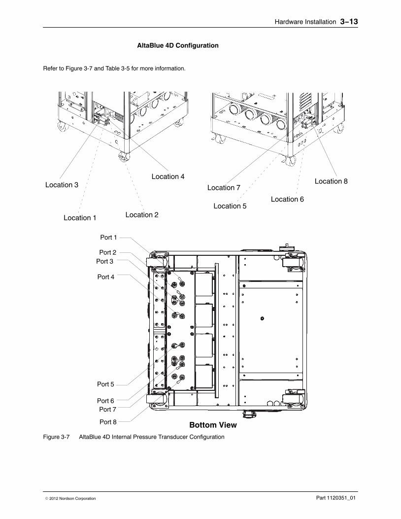
AltaBlue 4D Configuration
Refer to Figure 3-7 and Table 3-5 for more information.
Location 1
Location 3
Location 2
Location 4
Location 7
Location 5
Location 8
Location 6
Port 1
Port 2
Port 3
Port 4
Port 5
Port 6
Port 7
Port 8 Bottom View
Figure 3-7 AltaBlue 4D Internal Pressure Transducer Configuration
Hardware Installation3−14
Part 1120351_01 � 2012 Nordson Corporation
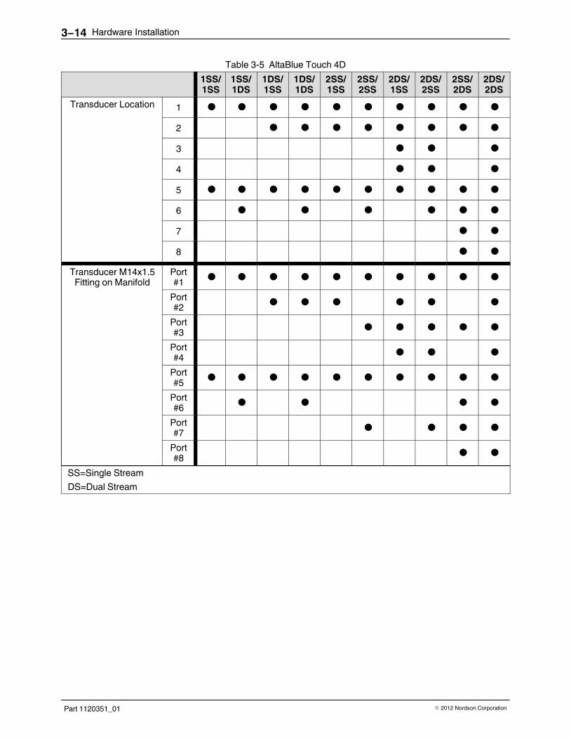
Table 3‐5 AltaBlue Touch 4D
1SS/1SS
1SS/1DS
1DS/1SS
1DS/1DS
2SS/1SS
2SS/2SS
2DS/1SS
2DS/2SS
2SS/2DS
2DS/2DS
Transducer Location 1 � � � � � � � � � �
2 � � � � � � � �
3 � � �
4 � � �
5 � � � � � � � � � �
6 � � � � � �
7 � �
8 � �
Transducer M14x1.5Fitting on Manifold
Port#1 � � � � � � � � � �
Port#2 � � � � � �
Port#3 � � � � �
Port#4 � � �
Port#5 � � � � � � � � � �
Port#6 � � � �
Port#7 � � � �
Port#8 � �
SS=Single Stream
DS=Dual Stream

Hardware Installation 3−15
Part 1120351_01� 2012 Nordson Corporation
AltaBlue 100L Configuration
Refer to Figure 3-8 and Table 3-6 for more information.
Port 1
Port 2
Port 3
Port 4
Port 5
Port 6
Port 7
Port 8 Bottom View
Location 1Location 2 Location 3 Location 4
Location 5
Location 6
Location 7
Location 8
Figure 3-8 AltaBlue 100L Internal Pressure Transducer Configuration

Hardware Installation3−16
Part 1120351_01 � 2012 Nordson Corporation
Table 3‐6 AltaBlue Touch 100L
1SS 1SS/1SS
2SS/1SS
2SS/2SS
2DS/1SS
2DS/2SS
2SS/2DS
2DS/2DS
Transducer Location 1 � � � � � � � �
2 � � �
3 � � � � � �
4 � � �
5 � � � � � � �
6 � �
7 � � � �
8 � �
Transducer M14x1.5Fitting on Manifold
Port#1 � � � � � � � �
Port#2 � � �
Port#3 � � � � � �
Port#4 � � �
Port#5 � � � � � � �
Port#6 � �
Port#7 � � � �
Port#8 � �
SS=Single Stream
DS=Dual Stream

Hardware Installation 3−17
Part 1120351_01� 2012 Nordson Corporation
Flow and Option Board Internal Transducer Cable Assignments
Pumps 3 and 4
Pumps 1 and 2
Channel 4
Channel 12
Channel 11
Channel 10
Channel 9
Channel 3
Channel 2
Channel 1
Figure 3-9 Connecting Internal Pressure Transducer Channels Directly to the Flow and Pressure Option Board.
Hardware Installation3−18
Part 1120351_01 � 2012 Nordson Corporation
Installing Flow Meter/Encoders (Optional)
In addition to the Flow meter and encoder, you must also install a pressuretransducer, which is required for pressure build.
Pressure Build allows the system to maintain a minimal constant pressure ifthe line speed drops below a specified line speed value, as well as relievesresidual pressure when the line is stopped.
Prerequisites
� The Flow/Pressure Option Board and Terminal Block has already
been installed.
� At least one pressure transducer has been installed and calibrated.
� Disconnect and lock out power to the melter. Remove the front panel,
and then open the electrical enclosure door.
Required Tools
5/32 in.,5 mm, 6 mm socket head wrench, 18 mm socket wrench, 3 mm flatblade screwdriver.

Hardware Installation 3−19
Part 1120351_01� 2012 Nordson Corporation
X
Terminal Block
-19x11 for
pumps 1 and 2
Step 1
Step 2
Step 3Step 4
Cable passthrough holes
Terminal Block
-19X51 for
pumps 3 and 4
Figure 3-10 Graphical Instructions for Installing the Flow Meter and Encoder
1. Assemble the Flow meter and encoder with 4 screws as shown in Figure 3‐10.
2. Do the following to continue:
� Mount the assembled Flow device directly to the applicator.
� Connect the incoming/outgoing hoses supplying the glue through the
flow meter.
3. Run the flow cable into the melter using the cable pass through holes.
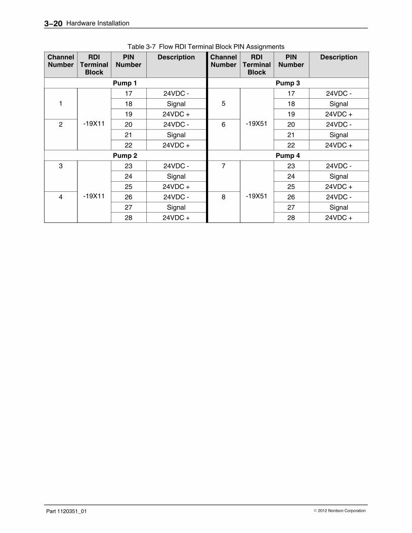
4. Connect the Flow channel to the Flow and Pressure Option Board usingthe RDI Terminal 34-pin Block. Refer to Table 3‐7 for PIN numberassignments.
Hardware Installation3−20
Part 1120351_01 � 2012 Nordson Corporation
Table 3‐7 Flow RDI Terminal Block PIN Assignments
ChannelNumber
RDITerminal
Block
PINNumber
Description ChannelNumber
RDITerminal
Block
PINNumber
Description
Pump 1 Pump 3
1
-19X11
17 24VDC -
5
-19X51
17 24VDC -
18 Signal 18 Signal
19 24VDC + 19 24VDC +
2 20 24VDC - 6 20 24VDC -
21 Signal 21 Signal
22 24VDC + 22 24VDC +
Pump 2 Pump 4
3
-19X11
23 24VDC - 7
-19X51
23 24VDC -
24 Signal 24 Signal
25 24VDC + 25 24VDC +
4 26 24VDC - 8 26 24VDC -
27 Signal 27 Signal
28 24VDC + 28 24VDC +

Hardware Installation 3−21
Part 1120351_01� 2012 Nordson Corporation
Flow Cable Wire Definition
The following details the wire definition for the flow cable.
2
34
5
6
7
1
1
2
3
5
7
4
6
1
2
3
Blue
Red
Green
Minus -
A
Plus +
Minus -
A
Plus +
B
N/A
N/A
N/A
35mm
Figure 3-11 Flow Cable Wire Definition
Hardware Installation3−22
Part 1120351_01 � 2012 Nordson Corporation
Operation 4−1
Part 1120351_01� 2012 Nordson Corporation
Section 4
Operation
WARNING! Allow only qualified personnel to perform the following tasks.Follow the safety instructions in this document and all other relateddocumentation.
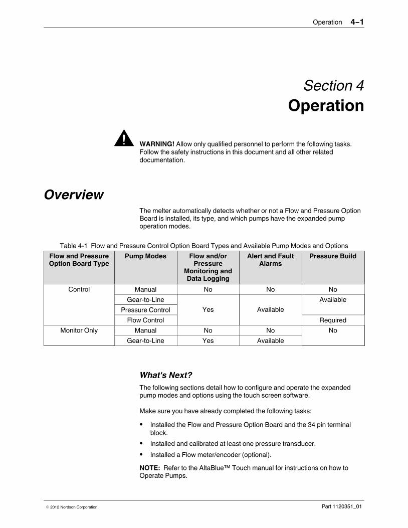
OverviewThe melter automatically detects whether or not a Flow and Pressure OptionBoard is installed, its type, and which pumps have the expanded pumpoperation modes.
Table 4‐1 Flow and Pressure Control Option Board Types and Available Pump Modes and Options
Flow and PressureOption Board Type
Pump Modes Flow and/orPressure
Monitoring andData Logging
Alert and FaultAlarms
Pressure Build
Control Manual No No No
Gear-to-Line
Yes Available
Available
Pressure Control
Flow Control Required
Monitor Only Manual No No No
Gear-to-Line Yes Available
What's Next?
The following sections detail how to configure and operate the expandedpump modes and options using the touch screen software.
Make sure you have already completed the following tasks:
� Installed the Flow and Pressure Option Board and the 34 pin terminal
block.
� Installed and calibrated at least one pressure transducer.
� Installed a Flow meter/encoder (optional).
NOTE: Refer to the AltaBlue™ Touch manual for instructions on how toOperate Pumps.

Operation4−2
Part 1120351_01 � 2012 Nordson Corporation
Changing Pump Operation Modes
Before changing to a different pump operation mode:
� You must have already installed the required flow and/or pressure
hardware.
� The Master Pump Control switch is OFF.
� You have sufficient adhesive in the hopper.
� The Master Heater Control switch is ON.
NOTE: It does not matter if the pump is enabled or disabled.
Heaters: OnPumps: OnPassword: Disabled Ready/OK
Recipes
MasterControls
Manual
43 RPM
Set Point:
43 RPM
Set Point:
43 RPM
Set Point:
43 RPM
Set Point:Manual Manual Manual
Hopper
Set Point:
175�C
Reservoir
Set Point:
175�C
Zone 1A
Set Point:
175�C
Zone 1B
Set Point:
175�C
Zone 2A
Set Point:
175�C
Zone 2B
Set Point:
175�C
Zone 3A
Set Point:
175�C
Zone 3B
Set Point:
175�C
Zone 4A
Set Point:
175�C
Zone 4B
Set Point:
175�C
Zone 5A
Set Point:
175�C
Zone 5B
Set Point:
175�C
Zone 6A
Set Point:
175�C
Zone 6B
Set Point:
175�C
Zone 7A
Set Point:
175�C
Zone 7B
Set Point:
175�C
Pump 1 Pump 2 Pump 3 Pump 4
System Status:Nothing Loaded
Pump 1Done
Pump 1
Enabled
Change Operation
FlowMode
Adjust Speed
Create/Modify Name
Pump 1
Manage ChannelSettings
Monitor
Total Adhesive Used
TestGraphingPump 1/ Operation Mode
Done
Manual
Gear-to-Line
Pressure Control
Flow Control
Home
Figure 4‐1 Changing Pump Operation Modes
1. From the Operator Display, touch the pump that you want to change itsoperation mode.
2. Touch Change Operation Mode and select the operation mode youwant for this pump.
3. Touch Done to continue. Refer to the appropriate section to continue.

Operation 4−3
Part 1120351_01� 2012 Nordson Corporation
Configuring and Modifying Pressure Control and Monitor
Pressure Control delivers consistent adhesive output by varying pump speedto control system pressure proportional to the line speed.
Tip: Rather than guessing or using the trial and error method to determinethe correct minimum and maximum pressure set point values, do thefollowing while in Gear-to-Line mode:
� Run at maximum production speed. Access the Monitor screen (refer
to Monitoring and Data Logging on page 4-25) and write down theobserved pressure (PSI, Bar or kPa) value. When configuring apressure input channel, use that value as the Maximum Set PointPressure.When done, run at minimum production speed. Access the Monitorscreen and write down the observed pressure (PSI, Bar or kPa) value.When configuring a pressure input channel, use that value as theMinimum Set Point Pressure.
The following shows the sequence of tasks associated with configuringPressure Control and Pressure Monitoring.
Pressure Control
Configure a pressure inputchannel with Control
Pressure build (optional)
Test
Configuration
Configure additional pressureand/or flow monitor only
input channels
Configure channel alert andfault alarm settings
Pressure Monitoring
Configure a pressure input channel
(optional)
NOTE:
� Pressure control requires at least one pressure input channel
configured with control.
� The pressure build option is only available on the same pressure
input channel configured with control.

Operation4−4
Part 1120351_01 � 2012 Nordson Corporation
� You can configure other pressure and flow input channels as monitor
only.
� You can only configure one pressure input channel with control.
Pump 1/ Channel SettingsDone
Configure Global
Help
Flow Settings
Manage ChannelAlert/Fault Settings
Configure Channels
Test Configuration
View Settings
Home
Pump 1/ Configure ChannelsDone
Help
Flow C1P Sensor 1
Not Configured
Flow C2
Configured
P Sensor 2
P Sensor 5
P Sensor 6
Configured
Configured
Not Configured
Not Configured
Control Pressure ControlFlow
Home
1. From the Operator Display, touch the pump that you want to change itsoperation mode. Touch Change Operation Mode and select PressureControl. Touch Done.
2. Touch Manage Channel Settings, then Configure Channels.
3. Decide what you want to do:
� To configure or modify a control pressure input channel, proceed to
step 4.
� To configure or modify a monitor only pressure or flow input channel,
proceed to step 5.
NOTE: If you plan to configure a flow monitor only input channel, touchConfigure Global Flow Settings and provide the required information.Refer to Tables 4‐2 and 4‐3 for more information.

Operation 4−5
Part 1120351_01� 2012 Nordson Corporation
4. Configure a control pressure channel. Refer to Table 4‐4 for moreinformation.
Touch Description
To designate the pressure channel you want tocontrol the pump.
P Sensor #
Not Configured
To configure or modify the corresponding controlpressure channel. Provide the required information.
Since this channel has control capabilities, you candecide whether or not you want to make use of thepressure build option.
Pressure build allows the system to maintain aminimal constant pressure if the line speed dropsbelow a specified line speed %.
Other benefits include:
� Decreases pressure response time on line
start-up.
� Decreases hammer-head effects when the
line stops and the adhesive is under highpressure.
� Relieves residual pressure when the line is
stopped.
NOTE: If you do not use pressure build, themotor control switches to Gear-to-Line modewhen the line speed drops below the defined setpoint.
� Proceed to step 5 to configure or modify monitor
only pressure and/or flow channels.
5. Configure a monitor only pressure or flow channel. Refer to Table 4‐4 formore information.
Touch Description
P Sensor #
Not Configured
To configure or modify monitor only pressure or flowchannel. Provide the required information.
� Repeat this step for each available pressure
and/or flow input channel.
� Refer to Table 4‐4 for flow specific information.
6. Decide what you want to do next.
Touch… To …. Refer topage…
Test Configuration(Control only)
Test and if necessary fine-tune the pressure control settings withyour manufacturing process.
4-13
Manage ChannelAlert/Fault Alarms(optional)
Configure and enable/disable alert and fault pressure and/or flowalarms.
NOTE: You must first configure the flow or pressure input channelbefore configuring its alarms.
4-21
Operation4−6
Part 1120351_01 � 2012 Nordson Corporation
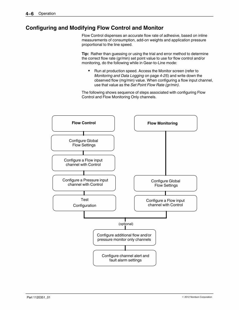
Configuring and Modifying Flow Control and Monitor
Flow Control dispenses an accurate flow rate of adhesive, based on inlinemeasurements of consumption, add-on weights and application pressureproportional to the line speed.
Tip: Rather than guessing or using the trial and error method to determinethe correct flow rate (gr/min) set point value to use for flow control and/ormonitoring, do the following while in Gear-to-Line mode:
� Run at production speed. Access the Monitor screen (refer to
Monitoring and Data Logging on page 4-25) and write down theobserved flow (mg/min) value. When configuring a flow input channel,use that value as the Set Point Flow Rate (gr/min).
The following shows sequence of steps associated with configuring FlowControl and Flow Monitoring Only channels.
Flow Control
Configure Global Flow Settings
Configure additional flow and/orpressure monitor only channels
Configure channel alert andfault alarm settings
Flow Monitoring
Configure a Flow inputchannel with Control
Test
Configuration
Configure a Pressure inputchannel with Control
Configure Global Flow Settings
Configure a Flow inputchannel with Control
(optional)
Operation 4−7
Part 1120351_01� 2012 Nordson Corporation
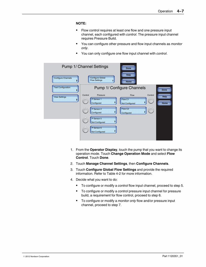
NOTE:
� Flow control requires at least one flow and one pressure input
channel, each configured with control. The pressure input channelrequires Pressure Build.
� You can configure other pressure and flow input channels as monitor
only.
� You can only configure one flow input channel with control.
Pump 1/ Channel SettingsDone
Configure Global
Help
Flow Settings
Manage ChannelAlert/Fault Settings
Configure Channels
Test Configuration
View Settings
Home
Pump 1/ Configure ChannelsDone
Help
Flow C1P Sensor 1
Not Configured
Flow C2
Configured
P Sensor 2
P Sensor 5
P Sensor 6
Configured
Configured
Not Configured
Not Configured
Control Pressure ControlFlow
Home
1. From the Operator Display, touch the pump that you want to change itsoperation mode. Touch Change Operation Mode and select FlowControl. Touch Done.
2. Touch Manage Channel Settings, then Configure Channels.
3. Touch Configure Global Flow Settings and provide the requiredinformation. Refer to Table 4‐2 for more information.
4. Decide what you want to do:
� To configure or modify a control flow input channel, proceed to step 5.
� To configure or modify a control pressure input channel for pressure
build, a requirement for flow control, proceed to step 6.
� To configure or modify a monitor only flow and/or pressure input
channel, proceed to step 7.

Operation4−8
Part 1120351_01 � 2012 Nordson Corporation
5. Configure a control flow channel.
Touch Description
To designate the flow channel you want to controlthe pump.
Flow C#
Configured
To configure or modify the corresponding controlflow channel. Provide the required information.
� Refer to Tables 4‐2 and 4‐3 for more
information.
� Proceed to step 6 to configure or modify control
pressure input channel with pressure build.
6. Configure a control pressure channel for pressure build.
Touch Description
To designate the pressure input channel you wantto control the pump (pressure build) when the linespeed drops below the user defined % line speed.
P Sensor #
Configured
To configure or modify the corresponding controlpressure channel for pressure build. Provide therequired information.
� Refer to Table 4‐4 for more information.
� Proceed to step 6 to configure or modify monitor
only pressure and/or flow channels.
7. Configure a monitor only pressure or flow input channel.
Touch Description
P Sensor #
Not Configured
To configure or modify a monitor only pressure orflow channel. Provide the required information.
� Repeat this step for each available pressure
and/or flow input channel.
� Refer to Tables 4‐2 and 4‐3 for more information
about flow settings.
� Refer to Table 4‐4 for more information about
pressure settings.
Operation 4−9
Part 1120351_01� 2012 Nordson Corporation
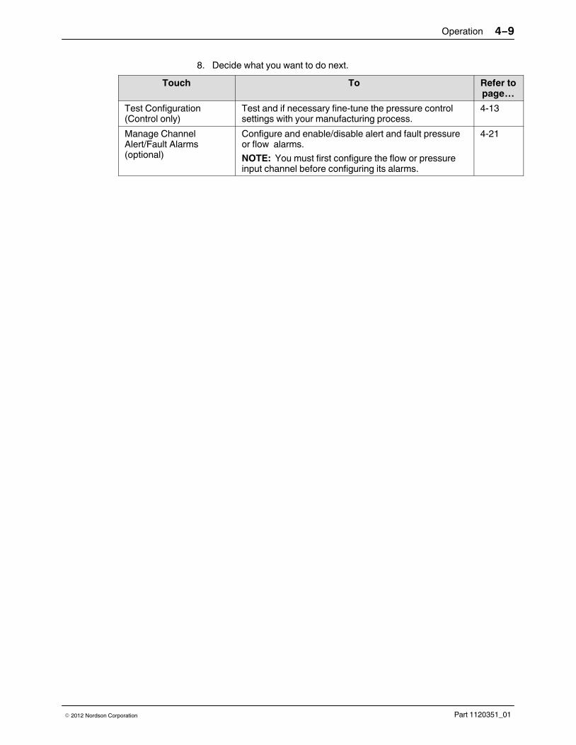
8. Decide what you want to do next.
Touch To Refer topage…
Test Configuration(Control only)
Test and if necessary fine-tune the pressure controlsettings with your manufacturing process.
4-13
Manage ChannelAlert/Fault Alarms(optional)
Configure and enable/disable alert and fault pressureor flow alarms.
NOTE: You must first configure the flow or pressureinput channel before configuring its alarms.
4-21

Operation4−10
Part 1120351_01 � 2012 Nordson Corporation
Viewing Total Adhesive Used
You can view and reset the amount of adhesive used for each configuredFlow channel.
Pump 1 Done
Pump 1
Enabled
Change Operation
FlowMode
Adjust Speed
Create/Modify Name
Pump 1
Manage ChannelSettings
Monitor
Total Adhesive Used
TestGraphingPump 1
Done
Home
Total Adhesive Used
Total Adhesive Used
Reset Adhesive Used Value
Reset Adhesive Used Value
Flow C1
Flow C2
1. From the Operator Display, touch the pump with Flow input channelsconfigured.
2. Touch Total Adhesive Used to view how much adhesive has been usedsince the last time you touched Reset Adhesive Used Value.

Operation 4−11
Part 1120351_01� 2012 Nordson Corporation
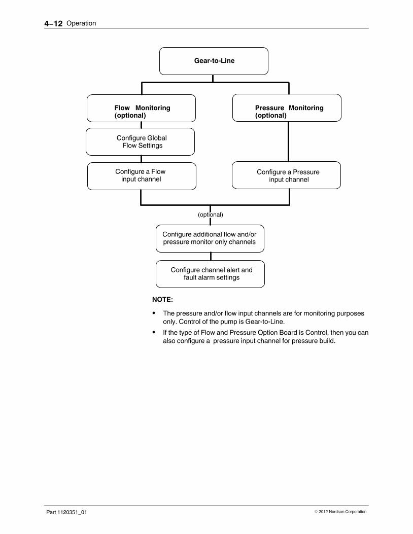
Configuring Gear-to-Line with Pressure/Flow Monitoring
Gear-to-Line delivers adhesive output at a rate proportional to the line speed.Depending on the type of configured channels, you can also monitor flowrates and/or pressure information as well.
Tip: Rather than guessing or using the trial and error method to determinethe correct flow rate or pressure set point value to use for flow/pressurecontrol and/or monitoring, do the following while in Gear-to-Line mode, and .:
� For flow monitoring, Run at production speed. Access the Monitor
screen (refer to Monitoring and Data Logging on page 4-25) thenwrite down the observed flow (mg/min) value. When configuring aflow input channel, use that value as the Set Point Flow Rate (gr/min).For pressure monitoring, Run at maximum production speed.Access the Monitor screen (refer to Monitoring and Data Logging onpage 4-25) then write down the observed pressure (PSI, Bar or kPa)value. When configuring a pressure input channel, use that value asthe Maximum Set Point Pressure. When done, run at minimum production speed. Access the Monitorscreen and write down the observed pressure (PSI, Bar or kPa) value.When configuring a pressure input channel, use that value as theMinimum Set Point Pressure.
The following shows sequence of steps associated with configuring PressureControl and Pressure Monitoring Only channels.
Operation4−12
Part 1120351_01 � 2012 Nordson Corporation
Flow Monitoring(optional)
Configure Global Flow Settings
Pressure Monitoring(optional)
Configure a Flow input channel
Configure a Pressure input channel
Gear-to-Line
(optional)
Configure additional flow and/orpressure monitor only channels
Configure channel alert andfault alarm settings
NOTE:
� The pressure and/or flow input channels are for monitoring purposes
only. Control of the pump is Gear-to-Line.
� If the type of Flow and Pressure Option Board is Control, then you can
also configure a pressure input channel for pressure build.
Operation 4−13
Part 1120351_01� 2012 Nordson Corporation
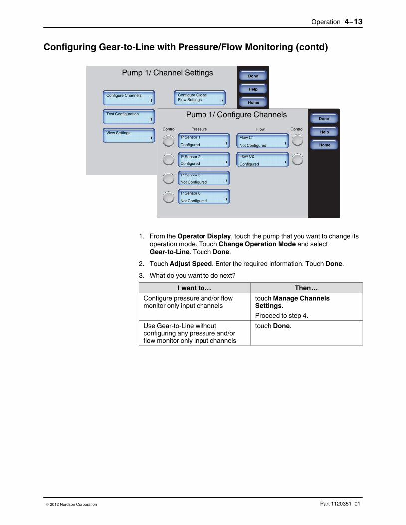
Configuring Gear-to-Line with Pressure/Flow Monitoring (contd)
Pump 1/ Channel SettingsDone
Configure Global
Help
Flow Settings
Manage ChannelAlert/Fault Settings
Configure Channels
Test Configuration
View Settings
Home
Pump 1/ Configure ChannelsDone
Help
Flow C1P Sensor 1
Not Configured
Flow C2
Configured
P Sensor 2
P Sensor 5
P Sensor 6
Configured
Configured
Not Configured
Not Configured
Control Pressure ControlFlow
Home
1. From the Operator Display, touch the pump that you want to change itsoperation mode. Touch Change Operation Mode and selectGear-to-Line. Touch Done.
2. Touch Adjust Speed. Enter the required information. Touch Done.
3. What do you want to do next?
I want to… Then…
Configure pressure and/or flowmonitor only input channels
touch Manage ChannelsSettings.
Proceed to step 4.
Use Gear-to-Line withoutconfiguring any pressure and/orflow monitor only input channels
touch Done.

Operation4−14
Part 1120351_01 � 2012 Nordson Corporation
4. What do you want to configure next?
I want toconfigure…
Then…
Flow Monitoring touch Configure Global Flow Settings button. Enterthe required information. Touch Configure Channelsthen a flow channel button to configure for it flowmonitoring purposes. Refer to Tables 4‐2 and 4‐3 formore information.
When done, proceed to step 5.
PressureMonitoring
touch Configure Channel Settings. Touch apressure channel button to configure for it pressuremonitoring purposes.
Refer to Table 4‐4 for more information.
NOTE: If the type of Flow and Pressure Option Boardis Control, then you can also configure a pressureinput channel for pressure build. Refer to Configuringand Modifying Pressure Control and Monitor formore information.
5. Decide if you want to configure alert/fault alarms for monitor onlychannels you just configured. Refer to page 4-21 for more information.

Operation 4−15
Part 1120351_01� 2012 Nordson Corporation
About Testing and Fine-Tuning Configurations
Although you may have configured many input channels, you are only testingand fine-tuning the configuration flow and/or pressure input channel that youdesignated with control.
The other input channels are for monitoring purposes only, and do not affector control the pump. When you are done testing the configuration, you canenable and configure channel alert/fault alarms to maintain optimumefficiency.
More About PIDs
PID is an acronym for Proportional, Integral, Derivative, which is a continuousfeedback loop that ensures the desired amount of adhesive. The systemtakes appropriate corrective action when there is a deviation from either theflow rate or pressure set point . These deviations could be caused byanything from a slight change in line speed, ambient temperature or due to ablockage in a filter or applicator.
PID Loops can be tuned manually or automatically using various techniques.Tuning techniques that compute PID constants only get you close to theoptimal system response. Manual adjustments are typically required forfine-tuning the system response.
Term Description
P Controls how fast the system responds to changes.
I Controls the offset error between the set point and the actual.
D Used to optimize the system response - but only if thefeedback signal is stable.
Note: Always leave the Derivative constant set to zero unlessthe feedback signal is very stable and noise free; otherwise,you may experience unstable system response.
Although default PID values are provided, they should be used as a startingpoint from which you can fine-tune to best suit your manufacturing process.
NOTE: Refer to textbooks or the Internet for proportional integral derivativeor PID Control for additional information.
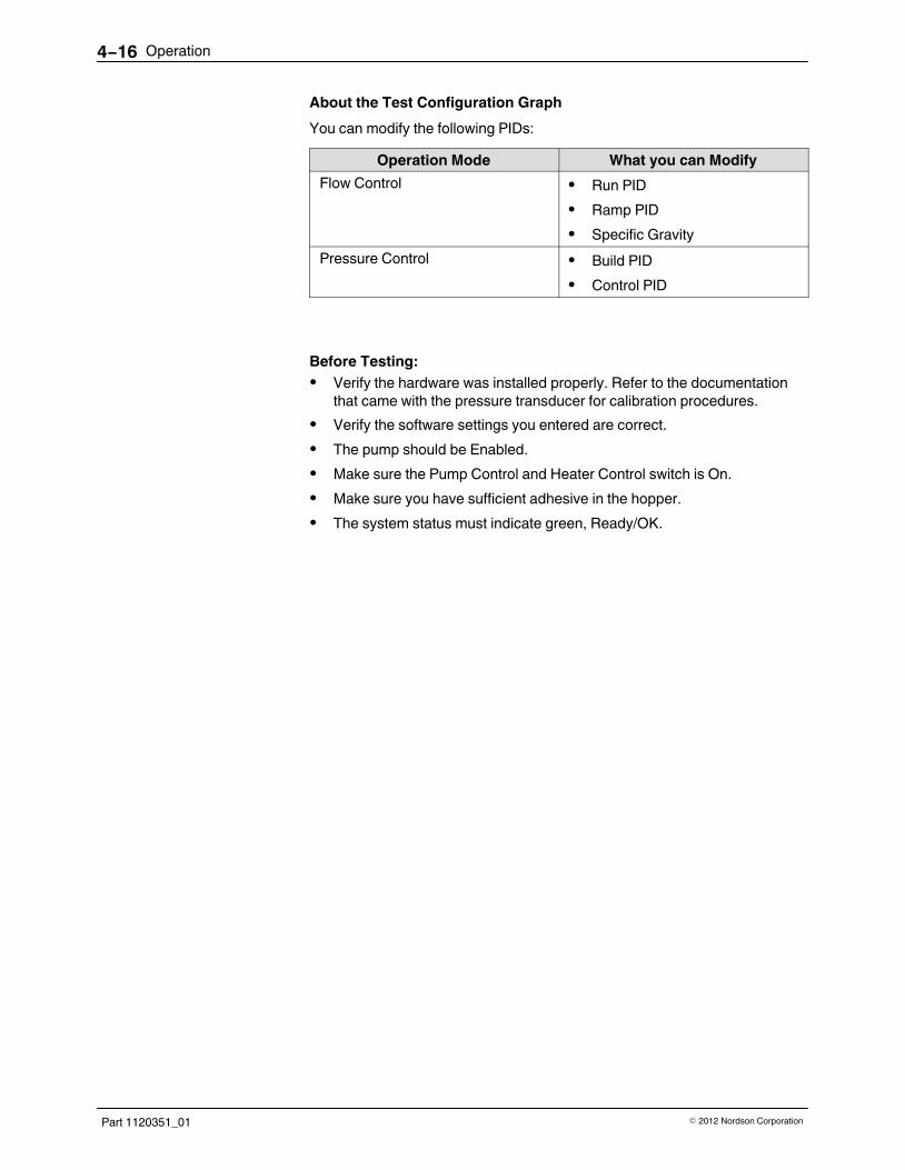
Operation4−16
Part 1120351_01 � 2012 Nordson Corporation
About the Test Configuration Graph
You can modify the following PIDs:
Operation Mode What you can Modify
Flow Control � Run PID
� Ramp PID
� Specific Gravity
Pressure Control � Build PID
� Control PID
Before Testing:
� Verify the hardware was installed properly. Refer to the documentation
that came with the pressure transducer for calibration procedures.
� Verify the software settings you entered are correct.
� The pump should be Enabled.
� Make sure the Pump Control and Heater Control switch is On.
� Make sure you have sufficient adhesive in the hopper.
� The system status must indicate green, Ready/OK.

Operation 4−17
Part 1120351_01� 2012 Nordson Corporation
Fine-Tuning Pressure Control
You can fine-tune Pressure Build and Pressure Control PIDs. The graphdisplays a % indicator beneath each PID button. The following formula isused to calculate this value:
% Error = 100*(Actual - Set Point)/Set Point
Keep in mind the following:
� The default screen display is 80 seconds.
� The screen displays 8 samplings per second.
� You can change PID values while a test is in progress. The results
appears within a second of viewing the test configuration screen.
� Pressure Build and Control PID % values are not running averages,
rather the % (plus or minus) is based on the current settings for thecurrent sample.
NOTE: It is not recommended enabling flow alert/fault alarms in pressurecontrol mode.
Done
P Sensor 1
P Sensor 1
DoneActual Pressure
Line Speed: RPM PSI Set Point Deviation %
Star Test
Build PID Control PID
Set Point
Motor% %
Pump 1
Home
1. Access the Test Configuration Graph.
From the OperatorDisplay
From the Operator Display, touch the pump thatyou want to test the control settings. TouchManage Channel Settings, then TestConfiguration.
From the PumpDisplay
Touch
Test Graphing
2. Get a base line reading. Touch Start Test to view the performance of thepump with the current settings. Touch the button again to stop the test.

Operation4−18
Part 1120351_01 � 2012 Nordson Corporation
3. Do the following to continue.
Touch Description
Build PID
To modify the P, I and D term values.
� Set both the I and D constants to 0 (zero).
� Increase the P constant until you see overshoot
with a minimal under shoot. Refer to Figure 4‐2.
Record this gain setting (Kpgg). Use smallchanges in line speed step for best accuracy,you don’t want the motor speed to go to 100%
� Measure the time (Tou) in seconds between the
overshoot peak and the undershoot valley.Compute PID constants with the followingequations:
� Kp = 0.7 * Kpgg
� Ki = 0.2 * Kpgg / Tou
� Kd = 0.29 * Kpgg * Tou
Control PID
To zoom in or increase the screen resolution.
To zoom out or decrease the screen resolution.
To toggle On or Off graphing the orange (RPM) line.
4. When you are satisfied with the results of testing, then do one of thefollowing:
� Configure monitor only pressure and/or flow channels. (Optional)
� Configure flow and/or pressure alert and fault alarms. (Optional)
When you are satisfied with the test configuration results, take note ofthe pressure at two different line speeds, then set up the appropriatealert/fault pressure set points using the observed pressure values atthe appropriate line speed.

Operation 4−19
Part 1120351_01� 2012 Nordson Corporation
Line speed set point (step) Tou
Actual Pressure
Figure 4‐2 Testing and Fine-tuning the Pressure Control Configuration

Operation4−20
Part 1120351_01 � 2012 Nordson Corporation
Fine-Tuning Flow Control
You can fine-tune Run and Ramp PIDs, as well as the Specific Gravity of theadhesive.
The graph displays a % indicator beneath each PID button. The followingformula is used to calculate this value:
% Error = 100*(Actual - Set Point)/Set Point
Keep in mind the following…
� Some flow meters have an oscillation in their signal that makes using
the D constant impractical. Each application should examine the flowsignal before deciding whether a D term should be used in the PID.
� Use Ramp PIDs when the line speed change is typically very fast.
� RAMP mode PID constants can be the same as the RUN mode
constants, but the ‘P’ constant is normally increased for fasterresponse under ramp conditions.
NOTE: Make sure the Drive Displacement (cc/rev) value is correct. If youare not sure, use the default value. Refer to Tables 4‐2 and 4‐3 for moreinformation.
P Sensor 1
Done
P Sensor 1
Pump 1
Flow C2
Flow C2
DoneActual Flow
Line Speed% RPM PSI Set Point Deviation %
Star Test
Ramp PID Run PID
Set Point
Motor% %
Flow (mg/min)
Specific Gravity:
Home
1. Access the Test Configuration Graph.
From the OperatorDisplay
From the Operator Display, touch the pump thatyou want to test the control settings. TouchManage Channel Settings, then TestConfiguration.
From the PumpDisplay
Touch
Test Graphing

Operation 4−21
Part 1120351_01� 2012 Nordson Corporation
2. Get a base line reading. Touch Start Test to view the performance of thepump with the current settings. Touch the button again to stop the test.
3. Verify the Drive Displacement (cc/rev) value is correct. Refer toConfiguring and Modifying Flow Control and Monitor.
� Set the P, I and D constants to 0 (zero) for Run and Ramp.
Increase the line speed and verify the actual flow rate graph is on topof the set point graph. If not, adjust the drive pump displacementparameter until the set point and actual graphs overlay each other.They do not have to overlay perfectly for the system to work well.
NOTE: The stability of the actual flow rate signal on the graph with allPID constants set to zero. If it is a flat line, you can use derivative terms tohelp tune the PID. If oscillation is present, keep the D term set to zero inthe PID section to avoid system instability
4. Do the following to fine-tune flow control. Refer to Fine Tuning PressureControl to tweak the pressure build PIDs.
Touch Description
Ramp PID
To modify the P, I and D term values. If the flowsignal contains significant jitter or oscillations, thendo the following:
� With the I and D RUN and RAMP constants set
to zero, increase the RUN and RAMP Pconstants (both set to the same value) until fastenough response is seen as the line speed isvaried.
� Running at a high, constant speed, increase the
RUN I constant until the error goes to zero. Usethe smallest I constant that eliminates the errorfor the fastest response.
� Leave the D constant set to zero.
NOTE: If the flow feed-back signal is stable, otherstandard tuning methods may be used (Good Gain,Ziegler-Nichols, Cohen-Coon, software tools, etc).
Run PID
To zoom in or increase the screen resolution.
To zoom out or decrease the screen resolution.
To toggle On or Off graphing the orange (RPM) line.

Operation4−22
Part 1120351_01 � 2012 Nordson Corporation
5. When you are satisfied with the results of testing, then do one of thefollowing:
� Configure monitor only pressure and/or flow channels. (Optional)
� Configure flow and/or pressure alert and fault alarms. (Optional)
Pressure can be monitored while operating in flow control mode.When you are satisfied with the test configuration results, take note ofthe pressure at two different line speeds, then set up the appropriatealert/fault pressure set points using the observed pressure values atthe appropriate line speed.
NOTE: It is not recommended enabling flow alert/fault alarms in pressurecontrol mode.
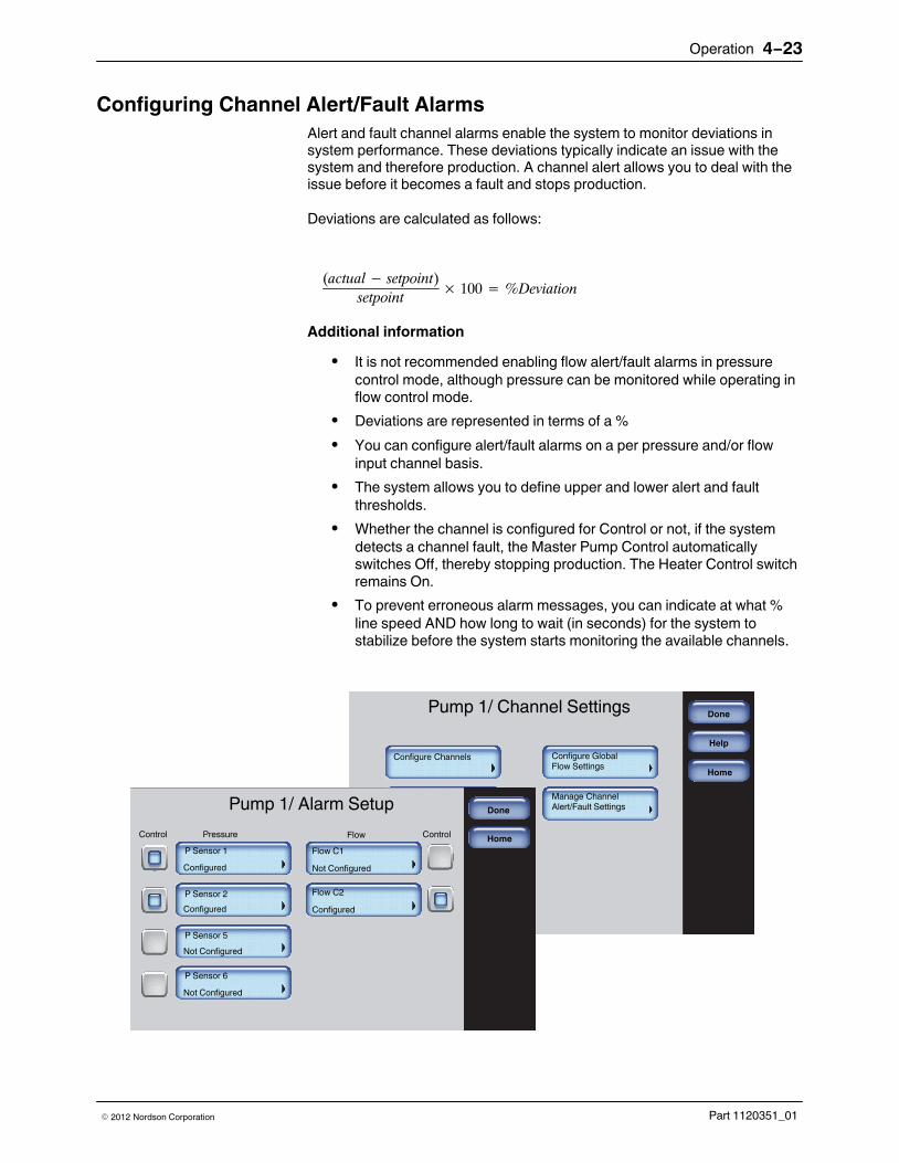
Operation 4−23
Part 1120351_01� 2012 Nordson Corporation
Configuring Channel Alert/Fault Alarms
Alert and fault channel alarms enable the system to monitor deviations insystem performance. These deviations typically indicate an issue with thesystem and therefore production. A channel alert allows you to deal with theissue before it becomes a fault and stops production.
Deviations are calculated as follows:
(actual� setpoint)
setpoint� 100 � %Deviation
Additional information
� It is not recommended enabling flow alert/fault alarms in pressure
control mode, although pressure can be monitored while operating inflow control mode.
� Deviations are represented in terms of a %
� You can configure alert/fault alarms on a per pressure and/or flow
input channel basis.
� The system allows you to define upper and lower alert and fault
thresholds.
� Whether the channel is configured for Control or not, if the system
detects a channel fault, the Master Pump Control automaticallyswitches Off, thereby stopping production. The Heater Control switchremains On.
� To prevent erroneous alarm messages, you can indicate at what %
line speed AND how long to wait (in seconds) for the system tostabilize before the system starts monitoring the available channels.
Pump 1/ Channel SettingsDone
Configure Global
Help
Flow Settings
Manage ChannelAlert/Fault Settings
Configure Channels
Test Configuration
View Settings
Home
Pump 1/ Alarm Setup Done
Home
Flow C1P Sensor 1
Not Configured
Flow C2
Configured
P Sensor 2
P Sensor 5
P Sensor 6
Configured
Configured
Not Configured
Not Configured
Control Pressure ControlFlow
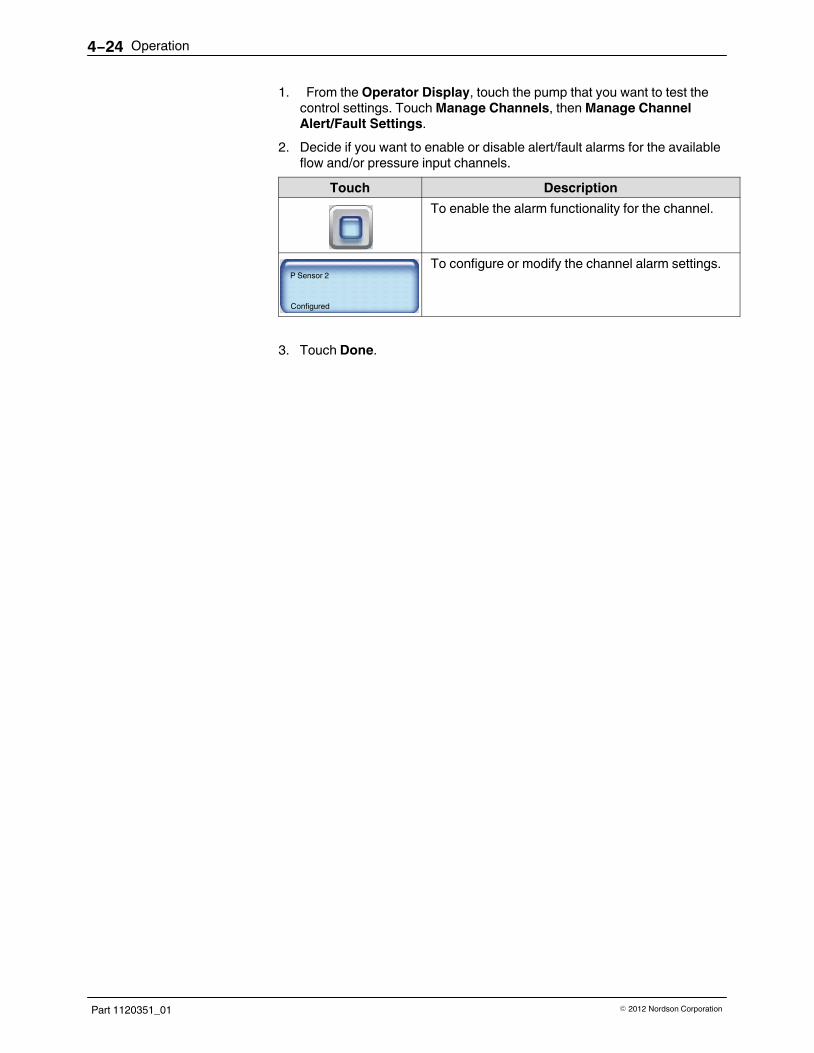
Operation4−24
Part 1120351_01 � 2012 Nordson Corporation
1. From the Operator Display, touch the pump that you want to test thecontrol settings. Touch Manage Channels, then Manage ChannelAlert/Fault Settings.
2. Decide if you want to enable or disable alert/fault alarms for the availableflow and/or pressure input channels.
Touch Description
To enable the alarm functionality for the channel.
P Sensor 2
Configured
To configure or modify the channel alarm settings.
3. Touch Done.
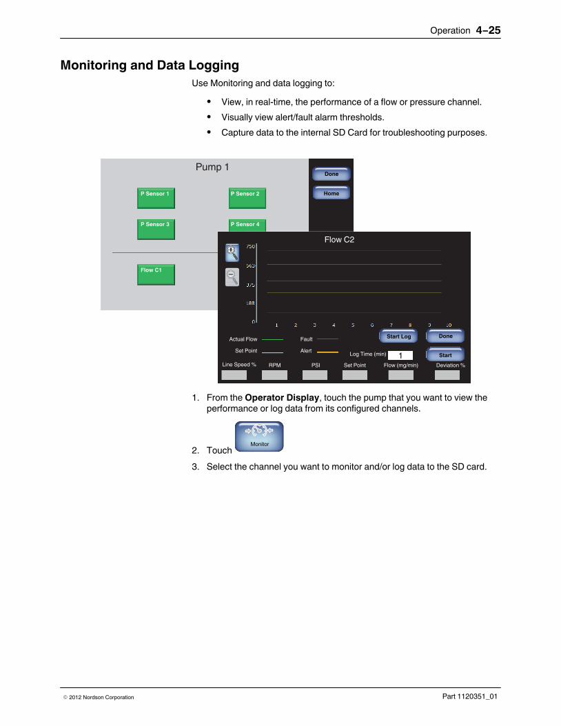
Operation 4−25
Part 1120351_01� 2012 Nordson Corporation
Monitoring and Data Logging
Use Monitoring and data logging to:
� View, in real-time, the performance of a flow or pressure channel.
� Visually view alert/fault alarm thresholds.
� Capture data to the internal SD Card for troubleshooting purposes.
Done
P Sensor 1
Pump 1
P Sensor 2
P Sensor 3 P Sensor 4
Flow C1 Flow C2
Flow C2
DoneActual Flow
RPM PSI Set Point Deviation %
Start
Start Log
Set PointLog Time (min)
Flow (mg/min)Line Speed %
Fault
Alert1
Home
1. From the Operator Display, touch the pump that you want to view theperformance or log data from its configured channels.
2. Touch Monitor
3. Select the channel you want to monitor and/or log data to the SD card.

Operation4−26
Part 1120351_01 � 2012 Nordson Corporation
4. Do the following to continue.
Touch Description
Start
To start/stop the monitoring process.
NOTE: You must touch this button to activate theStart Log button.
Start Log
a. To start/stop the monitoring process
b. Enter the amount of time (minutes) you want tolog data.
NOTE: The system creates a LOG.TXT file,located on the Internal SD Card. Refer toAccessing the SD Card for more information.
To zoom in or increase the screen resolution.
To zoom out or decrease the screen resolution.

Operation 4−27
Part 1120351_01� 2012 Nordson Corporation
Viewing Pump and Channel Settings
You can view pump and channel information from a single location, including
� General pump information
� Flow channel settings
� Pressure channel settings
Pump 1/ Channel SettingsDone
Configure Global
Help
Flow Settings
Manage ChannelAlert/Fault Settings
Configure Channels
Test Configuration
View Settings
Home
Pump 1/ Review Done
Home
Flow Channel Settings Pressure Channel Settings
Specific Gravity
Pump RPM (actual)
Pump RPM (set point)
Pump Displacement (cc/rev)
Operation Mode
Pump Name (user-defined)
Pump Name (default)
0.960
0
0
20.0
Pressure
Pump 2
Pump 2
General Information
5. From the Operator Display, touch the pump that you want to review itssettings.
1. Touch Configure Channels, then View Settings.
2. Touch Flow Channel Settings or Pressure Channel Settings to viewchannel specific information.

Operation4−28
Part 1120351_01 � 2012 Nordson Corporation
Accessing the SD Card
The system includes two SD Cards.
Customer SD Card
Internal SD Card
Figure 4-3 Location of the Customer and Internal SD Cards.
1. Switch the melter off, and disconnect the electrical power to the melter atthe local power source. Disassemble the front, to access the CPU board.
2. Remove the Internal SD card, and using a PC, view the LOG.TXT file.Refer to Figure 4‐3.
3. When done, replace the Internal SD Card, close and reassemble thefront. Reconnect power and switch On the melter.

Operation 4−29
Part 1120351_01� 2012 Nordson Corporation
Stop Using / Disable a Channel
Read the following to determine which applies to you:
If you … Then…
Want to replace the channel withthe exact same hardware andspecifications
You do not have to do anything.The channel software configurationretains its previous settings.
Want to replace the channel withdifferent hardware andspecifications
Refer to the appropriate pumpoperation mode section in thischapter that you want to use andfollow the instructions.
No longer want to make use of achannel and you do not want tophysically remove or disconnectanything
continue with the followinginstructions.
1. From the Operator Display, touch the pump that makes use of the flowor pressure channel you no longer want to use. Touch ManageChannels, then Configure Channels. Verify whether or not the channelis configured with Control.
2. Do one of the following to continue:
� If the channel is not configured with Control, then proceed to the next
step. Touch Done to continue.
� If the channel is configured with Control, then do one of the following.
Touch Done to continue.
‐ Select another channel to use for Control. Touch the button to verify
or modify its settings.
‐ Change the pump operation mode to Manual or Gear-to-Line.
‐ Disable the pump. Refer to the AltaBlue™ Touch Adhesive Melter
manual for more information.
3. Touch Manage Channel Alert/Fault Settings. Verify the Alarms optionfor the channel you no longer want to use is not enabled.
4. Touch Done.
NOTE: You may need to update your recipe.
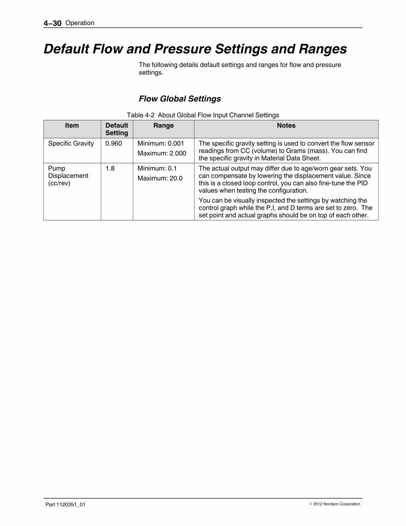
Operation4−30
Part 1120351_01 � 2012 Nordson Corporation
Default Flow and Pressure Settings and RangesThe following details default settings and ranges for flow and pressuresettings.
Flow Global Settings
Table 4‐2 About Global Flow Input Channel Settings
Item DefaultSetting
Range Notes
Specific Gravity 0.960 Minimum: 0.001
Maximum: 2.000
The specific gravity setting is used to convert the flow sensorreadings from CC (volume) to Grams (mass). You can findthe specific gravity in Material Data Sheet.
PumpDisplacement(cc/rev)
1.8 Minimum: 0.1
Maximum: 20.0
The actual output may differ due to age/worn gear sets. Youcan compensate by lowering the displacement value. Sincethis is a closed loop control, you can also fine-tune the PIDvalues when testing the configuration.
You can be visually inspected the settings by watching thecontrol graph while the P,I, and D terms are set to zero. Theset point and actual graphs should be on top of each other.

Operation 4−31
Part 1120351_01� 2012 Nordson Corporation
Flow Settings
Table 4‐3 About Flow Input Channel Settings
Item DefaultSetting
Ranges/Options
Notes
Flow ChannelName
Flow C# Minimum: 1
Maximum: 10
A channel flow name can include up to 10 alphanumericcharacters, including space, dash and underscorecharacters.
Encoder Pulses/ Revolution
1500 Minimum: 100
Maximum: 10000
Flow MeterDisplacement(cc / Revolution)
.93 Minimum: 0.1
Maximum: 20.0
Number ofStreams (per Flow meter)
2 1-20
Specific Gravity 0.960 Minimum: 0.001
Maximum: 2.000
The specific gravity setting is used to convert the flow sensorreadings from CC (volume) to Grams (mass). You can findthe specific gravity in Material Data Sheet.
Stop Threshold
Delta%LS is the change in line speed during the ramp
Delta Time is Delta Time’ is the time of the ramp
-10 makes sure the threshold set is lower than the actual acceleration
* 1000 makes for better resolution
1000 * (Delta%LS� 10)
DeltaTimeUse the following formula:
Delta Time
Flow control makes use of Run and Ramp operational modes, each with their own uniquePID constants. You can determine when the unit switches from Run to Ramp by enteringthe Minimum Acceleration - % Line Speed/Sec. You can then fine-tune the Run andRamp PIDs from the Test Configuration screen. Refer to page 4-16 for more information.
De
lta
% L
S
Delta%LS is the change in line speed during the ramp
Delta Time is Delta Time’ is the time of the ramp
-10 makes sure the threshold set is lower than the actual acceleration
* 1000 makes for better resolution
Note. If the Flow controller/monitor is used in an intermittent application, use the followingformula to calculate the minimum speed:
MLS = 0.6*GL whereMLS = minimum line speed (m/min)GL = gap length (mm)
Continued …

Operation4−32
Part 1120351_01 � 2012 Nordson Corporation
Flow Settings (contd)
Item DefaultSetting
Ranges/Options
Notes
Line Speed 100% Minimum: 0%
Maximum: 100%
Set Point Flow Rate
20 gr/min
Minimum: 1
Maximum: 500
Run Mode PIDs P: 3111
I: 623
D: 0
P: 0 - 50000
I: 0 - 50000
D: 0 - 50000Ramp ModePIDs
P: 5000
I: 300
D: 0
Flow AlertAlarms
High: 10%
Low: 10%
Minimum: 1%
Maximum: 100%
Flow FaultAlarms
High: 25%
Low: 25%
Minimum: 1%
Maximum: 100%

Operation 4−33
Part 1120351_01� 2012 Nordson Corporation
Pressure Settings
Table 4‐4 About Pressure Input Channel Settings
Item Default Setting Ranges/Options
Notes
PressureChannel Name
P Sensor # Minimum: 1
Maximum: 10
A channel pressure name can include upto 10 alphanumeric characters, includingspace, dash and underscore characters.
TransducerType
0-10V 0-10V
4-20 mA
0.1 - 10.1 V This information is located on thetransducer itself.Full Scale
Pressure1500 - PSI
103.42 - Bar
10342.13 - kPa
500 - 5000 PSI
34.47 - 344.74 Bar
3447.38 - 34473.78 kPa
Maximum/Minimum %Line Speed
100%
Minimum: 0%
Maximum: 100%
Maximum/Minimum SetPoint Pressure
500 - PSI
34.47 - Bar
3447.38 - kPa
0 - 1000 PSI
0 - 68.948 Bar
0 - 6894.757 kPa
Pressure Build Yes Yes
No
Only available with the channel selectedwith Control.
% Line SpeedThreshold
10% Minimum: 0%
Maximum: 100%
These pressure build settings allow youto configure at what point you want toswitch from Run mode to pressure buildmode.Pressure Set
Point50 - PSI
3.447 - Bar
344.7 - kPa
0 - 1000 PSI
0 - 68.948 Bar
0 - 6894.757 kPa
(Pressure) Buildand ControlPIDs
P: 2100
I: 585
D: 806
P: 0 - 50000
I: 0 - 50000
D: 0 - 50000
Pressure AlertAlarms
High: 20%
Low: 20%
Minimum: 1%
Maximum: 100%
Flow FaultAlarms
High: 50%
Low: 50%
Minimum: 1%
Maximum: 100%

Operation4−34
Part 1120351_01 � 2012 Nordson Corporation

Maintenance 5-1
Part 1120351_01� 2012 Nordson Corporation
Section 5
Maintenance
WARNING! Allow only qualified personnel to perform the following tasks.Follow the safety instructions in this document and all other relateddocumentation.
NOTE: Maintenance is an important preventive measure for maintainingoperating safety and extending the service life of the Flow applicator. Itshould never be neglected.

Maintenance5-2
Part 1120351_01 � 2012 Nordson Corporation
Relieving PressureWARNING: System and material pressurized. Relieve system pressurebefore disconnecting heated hoses. Failure to observe can result in seriousburns.
WARNING: Hot! Risk of burns. Wear safety goggles and heat-protectivegloves.
1. Set the motor speed of the unit feeding the material to 0 min-1; switch offthe motor(s).
2. Place a container under the TruFlow applicator nozzle or under thepressure relief valves or drain valves of the Flow Divider.
3. Manually operate the solenoid valves of the TruFlow applicator or openthe pressure relief valves / drain valves of the Flow Divider to allowadhesive to flow out. Collect the adhesive in the container.
4. Properly dispose of material according to local regulations.
Maintenance TableUnit part Activity Interval
Electrical cables Inspect for damage Daily
Air hoses Daily
Flow-Splitter Check for leakage Daily
Tighten fixing screws Every 500 hours of operation
Flow applicator External cleaning Daily
Check control module (whenpresent) for leakage
Daily
Replace control module When defective
Clean filter cartridge and replacefilter screen
Depending on degree ofadhesive pollution.
Recommendation: Every 100hours of operation
Flow Divider Purge with cleaning agent Regularly as required byoperating conditions or beforechanging the adhesive
Clean completely Depending on operatingconditions
Forcibly activate the safety valvepiston
Monthly

Maintenance 5-3
Part 1120351_01� 2012 Nordson Corporation
Electrical and Pneumatic Connecting Lines
Visual Inspection for External Damage
CAUTION: When damaged parts pose a risk to the operational safety ofthe Flow-Splitter, Flow applicator or Flow Divider and/or to the safety ofpersonnel, switch off the Flow-Splitter, TruFlow applicator or Flow Divider orthe entire application system and have the damaged parts replaced byqualified personnel. Use only original Nordson spare parts.
Flow‐Splitter
Checking for LeakageFlow-Splitters are equipped with a self-sealing shaft seal. Adhesive may dripout of the seal. The shaft seal must then be replaced.
NOTE: If the shaft seal needs to be replaced, Nordson recommendsreplacing the entire Flow-Splitter and sending the old one in to be repaired.
Figure 5-4
Replacing Shaft Seal
1. Detach the encoder.
2. Unscrew the pressure piece.
3. Carefully remove the seal. Do not use sharp tools! Ensure that thesealing surfaces are not damaged.
The seal is no longer needed and can be disposed of.
4. Clean the sealing surfaces (e.g. with a wooden or brass spatula). Do notburn out.
5. Insert the shaft seal. Position it properly (arrow).
6. Attach the pressure piece.
7. Install the encoder.
Figure 5-5NOTE: Nordson can assume no guarantee for a shaft seal that thecustomer replaces himself.

Maintenance5-4
Part 1120351_01 � 2012 Nordson Corporation
Tightening Fixing ScrewsNOTE: Tighten the fixing screws only when the unit is cold and only with atorque wrench.
Thermodynamic tension can cause the fixing screws to loosen.
Tighten fixing screws with 25 Nm every 500 hours of operation.

Maintenance 5-5
Part 1120351_01� 2012 Nordson Corporation
Flow Applicator
External CleaningExternal cleaning prevents impurities created during production fromcausing the unit to malfunction.
Always follow manufacturer’s instructions when using cleaning agents!
1. Electrically heat the applicator until the adhesive is liquid.
2. Thoroughly remove warm adhesive with a cleaning agent and/or a softcloth.
3. Remove dust, fluffs, etc. with a vacuum cleaner or a soft, lint-free cloth.
CAUTION: Do not damage or remove warning labels. Damaged orremoved warning labels must be replaced by new ones.
Changing MaterialNOTE: Before changing the type of material, determine whether the oldand new material may be mixed.
� May be mixed: Remaining old material can be flushed out using the new
material.
� May not be mixed: Thoroughly purge the unit with a cleaning agent
recommended by the material supplier.
NOTE: Properly dispose of the material and cleaning agent according tolocal regulations.
Cleaning Filter CartridgeNOTE: Remove the filter cartridge only when the applicator is hot and notunder pressure. Install only when the applicator is hot.
WARNING: Hot! Risk of burns. Wear safety goggles and heat-protectivegloves.
WARNING: System and adhesive pressurized. Relieve system of pressurebefore replacing a filter cartridge. Failure to observe can result in seriousburns.

1
2
Maintenance5-6
Part 1120351_01 � 2012 Nordson Corporation
Removing Filter Cartridge1. Place a container under the filter bore.
NOTE: Use a second open-end wrench when screwing in and out thepressure relief screw (1, Fig. 24). This prevents the filter cartridge (2, Fig. 24) from turning.
2. Screw the pressure relief screw out of the filter cartridge until adhesiveflows out.
3. Simultaneously press the filter cartridge in and turn counterclockwise(bayonet fastener), then extract it. Use an open-end or ring wrench (size 17), if necessary.
Figure 5-6
NOTE: If the filter cartridge is stuck in the filter bore, grasp the filtercartridge with a pliers and extract.
4. Purge the filter bore by allowing the pump to run briefly with adhesive.This rinses out particles of dirt that may still be in the filter bore.
5. Properly dispose of adhesive according to local regulations.
Replacing Filter ScreenWARNING: Hot! Risk of burns. Wear heat-protective gloves.
1 2 3 4 5
Figure 5-7
1 Pressure relief screw
2 O‐ring
3 Filter screw
4 O‐ring
5 Filter screen with spring
1. Heat the filter cartridge until adhesive is liquid.
2. Turn the unit consisting of pressure relief screw, filter screen and springcounterclockwise out of the filter screw, then replace.
NOTE: Nordson recommends keeping a supply of replacement filtercartridges to avoid interruptions in production.

Maintenance 5-7
Part 1120351_01� 2012 Nordson Corporation
Installing Filter Cartridge1. Heat the Flow applicator until adhesive is liquid.
2. Apply high temperature grease to the O-ring.
(can, 10 g, P/N 394769; tube, 250 g, P/N 783959)
3. Slide the filter cartridge into the filter bore.
NOTE: Air penetrates the filter bore when the filter cartridge is replaced.The Flow applicator is deaerated with the aid of the pressure relief screw.
4. Unscrew the pressure relief screw somewhat.
5. Allow the pump to run briefly until adhesive flows out. This forces out air.
6. Turn in the pressure relief screw clockwise all the way when theadhesive flows out free of bubbles.

X
Maintenance5-8
Part 1120351_01 � 2012 Nordson Corporation
Flow Divider
Purging with Cleaning Agent
CAUTION: Use only a cleaning agent recommended by the adhesivemanufacturer. Observe the Material Safety Data Sheet for the cleaningagent.
Before starting production again, flush out residue of the cleaning agentusing the new adhesive.
NOTE: Properly dispose of cleaning agent according to local regulations.
WARNING: Hot! Risk of burns. Wear safety goggles and heat-protectivegloves.
WARNING: Risk of explosion or fire. Fire, open flames, and smokingprohibited.
Cleaning Complete Flow Divider
CAUTION: Use only a cleaning agent recommended by the adhesivemanufacturer. Observe the Material Safety Data Sheet for the cleaningagent.
The Flow Divider must be regularly detached and cleaned.
Forcibly Actuating Safety ValveForcibly actuate the safety valve piston once a month. This preventsmaterial from blocking the safety valve.
1. Relieve pressure to the Flow Divider. If there are pressure relief screws,open them. Collect the escaping material and dispose of properly.
2. Disconnect all hoses.
3. Close hose connections with proper Nordson plugs.
4. Measure and make a note of the insertion depth (dimension X in theillustration) of the adjusting screw. This allows the insertion depth to bereproduced.
Figure 5-85. Run the metering station at full speed with the hose connections closed.
Switch the motor on and off several times during operation.

Maintenance 5-9
Part 1120351_01� 2012 Nordson Corporation
Flow General and Technical DataName UTA-... (Universal TruFlow Applicator / Flow Divider)
Type of heating Electrical resistance heating elements
Temperature sensors Pt 100 / Ni 120
Max. processable viscosity
Speed-Coat, TrueCoat 25000 mPas 25000 cP
UM25, UM50 500 to10000
mPas 500 to10000
cP
Max. application width 500 mm
Min. number of control modules perstream
1 With UM50 1
Max. number of control modules perstream
3 With UM50 1
Max. number of control modules perapplicator
24 With UM50 12
Installation height (distance between nozzle and substrate)
Speed-Coat
Recommendation Contact Contact
TrueCoat
Recommendation Contact Contact
CF
Recommendation 19 to 51 mm 0.75 to 2 inch
Meltblown
Recommendation 19 to 51 mm 0.75 to 2 inch
Summit
Recommendation 12 to 25 mm 0.5 to 1 inch
SureWrap
Recommendation Contact Contact

Maintenance5-10
Part 1120351_01 � 2012 Nordson Corporation
Temperatures
Max. ambient temperature 60 °C 140 °F
Max. operating temperature forsolenoid valves
80 °C 176 °F
Max. operating temperature forapplicator
200 °C 392 °F
Spray air temperature
Meltblown
Recommendation 16 to 27 �C (30 to 50 �F) higher than the adhesive temperature
CF, Summit, SureWrap
Recommendation 9 to 15 �C (15 to 25 �F) higher than the adhesive temperature
Air pressure
Control air approx. 4 to6 bar
approx. 0.4to 0.6 MPa
approx. 58to 87 psi
Spray/application air
Speed-Coat, TrueCoat approx. 0.8to 1.5 bar
approx. 0.08to 0.15 MPa
approx. 11.6to 21.7 psi
CF
Recommendation
0.3 to 3.4
0.8 to 1.2
bar
bar
0.03 to 0.34
0.08 to 0.12
MPa
MPa
5 to 50
12 to 18
psi
psi
Meltblown
Recommendation 2.1 to 3.1 bar 0.21 to 0.31 MPa 30 to 45 psi
Summit
Recommendation 0.3 to 1.7 bar 0.03 to 0.17 MPa 5 to 25 psi
Sure Wrap
Recommendation
0.5 to 1.5
0,8
bar
bar
0.05 to 0.15
0,08
MPa
MPa
7 to 22
12
psi
psi
Air consumption UM control modules � 7.1 to 56.6 nlm (� 0.25 to 2.0 scfm)
Dependent on type of application:
More for Meltblown, less for Summit

Maintenance 5-11
Part 1120351_01� 2012 Nordson Corporation
Electrical Data
WARNING! The applicator is designed for only one operating voltage.Operate only at the operating voltage shown on the ID plate.
Operating voltage 230 VAC
Operating voltage frequency 50/60 Hz
Voltage for solenoid valve Without overexcitation! max. 24 VDC
Refer to section 3 Installation: Connecting Solenoid Valves
Starting current ION solenoid valve 2 A for P/N 7157157
Power consumption body 250 mm
Degree of protection IP 30
Dimensions and Weights
Dimensions Refer to technical drawing
Weight See consignment note
Processing MaterialsDesignation Order number Use
High temperature grease Apply to O-rings and threads
NOTE: The grease should not bemixed with other lubricants.Oily/greasy parts must be cleanedbefore application.
� Can 10 g P/N 394769
� Tube 250 g P/N 783959
� Cartridge 400 g P/N 402238
TorquesScrews Torque
Air cap 1.7 Nm (15 lbin)
Control module-body 3.4 Nm (30 lbin)
Nozzle clamp 1.7 Nm (15 lbin)
CF nozzle 3.4 Nm (30 lbin)
CF nozzle (Unibody) 0.6 Nm (5 lbin)

Maintenance5-12
Part 1120351_01 � 2012 Nordson Corporation
Pressure Transducer MaintenanceThe following table lists some common maintenance tasks. Refer to thedocumentation that came with pressure transducer for more information.
Unit Part Activity Interval
Entire sensor Check performance Dependent on purpose and conditionsof use of sensor
Calibrate zero point Every year, or more often if conditionsof use requireCalibrate
Separating membrane Check for damage With every performance check, moreoften if necessaryCheck if hardened or charred material
is stuck to the membrane. Clean ifnecessary

Troubleshooting 6-1
Part 1120351_01� 2012 Nordson Corporation
Section 6
Troubleshooting
WARNING! Allow only qualified personnel to perform the following tasks.Follow the safety instructions in this document and all other relateddocumentation.
This section contains troubleshooting procedures. These procedures coveronly the most common problems that you may encounter. If you cannotsolve the problem with the information given here, contact your local Nordsonrepresentative for help.
Refer to the Toubleshooting section of the AltaBlue™ Touch manual foradditional touchscreen, system and pump information.

Troubleshooting6-2
Part 1120351_01 � 2012 Nordson Corporation
Flow and Pressure Alerts/Faults Pop-up Messages
The table column titled Alert\Fault Message lists the possible flow and/orpressure channel alert or fault pop-up messages. Use the Possible Causeand Corrective Action columns to help resolve the alert or fault condition.
Alert\Fault Message Possible Cause Corrective Action
1. Flow Warning onChannel #
The flow rate is either above orbelow defined alert threshold %deviation.
� Check flow configuration settings.
� Modify the high and low alert
threshold values.
2. Flow Fault on Channel #
The flow rate is either above orbelow defined fault threshold %deviation.
� Check flow configuration settings.
� Modify the high and low fault
threshold values.
3. Pressure Warning onChannel #
The pressure is either above orbelow defined alert threshold %deviation.
� Check flow configuration settings.
� Modify the high and low alert
threshold values.
4. Pressure Fault on Channel #
The pressure is either above orbelow defined fault threshold %deviation.
� Check flow configuration settings.
� Modify the high and low fault
threshold values.
5. 4-20mA or 0.1-10.1VPressure Input #disconnected
No power detected between thecable connecting the pressuretransducer to the melter.
� Make sure the connections are
properly seated.
� Visually check the cable for
damage.
6. 4-20mA or 0.1-10.1VLine Speed Input #disconnected
No power detected between thecable connecting the line speeddevice to the melter.
� Make sure the connections are
properly seated.
� Visually check the cable for
damage.
7. 24V Power ShortDetected
An event occurred causing thepower supply shorted out.
Replace the 24V power supply.
8. 24V Power ShortDetected toPressure/Flow board
An event happened, causing theFlow and Pressure Option boardshort out.
Replace the Flow and PressureOption board.
9. Communicationsheartbeat fault
Communication between themelter and/or motor control board.
� Visually check the wiring for
damage.
� Replace the fieldbus card.
10. # Motor drive fault The motor is no longer able tooperate.
Replace the motor.
11. Motor # OTthermostat fault
The motor is no longer able tooperate.
Replace the motor.

Troubleshooting 6-3
Part 1120351_01� 2012 Nordson Corporation
Troubleshooting Flow Rate Issues
The table column titled Problem lists the possible flow issues. Use thePossible Cause and Corrective Action columns to help resolve theproblem.
Problem Possible Cause Corrective Action
1. Leakage at pumpshaft seal
Pump shaft seal is worn Have Flow-Splitter repaired
2. Adhesive pressuretoo low, outputquantity too low
Flow-Splitter is worn Replace Flow-Splitter
3. Flow-Splitter blocked c. Processed material too cold
d. Foreign matter in Flow-Splitter
a. Change temperature setting(observe data sheet of adhesivemanufacturer)
b. Purge Flow-Splitter with solvent,otherwise replace Flow-Splitter
4. Flow applicator doesnot heat
a. Temperature not set
b. Plug not connected
c. Fuses in melter defective
d. Heater cartridge(s) in Flowapplicator defective
a. Check settings and modify ifrequired.
b. Connect plug
c. Disconnect unit from line voltage,check fuses and replace ifnecessary
d. Replace
5. Flow applicator doesnot reach the settemperature
Ambient temperature too low Increase ambient temperature
Maximum ambient temperature is60�C (140�F). Maximum operatingtemperature for applicator is 200�C(392�F)
6. No adhesive a. Reservoir is empty
b. Master Pump Control is Off
c. Melter pump is not working
a. Fill reservoir with adhesive
b. Access the Master Controldisplay and switch on the PumpControl
c. Check, and replace if necessary
Continued…

Troubleshooting6-4
Part 1120351_01 � 2012 Nordson Corporation
Corrective ActionPossible CauseProblem
7. No adhesive at outlet a. Flow applicator has not yetreached operating temperature
b. Compressed air not connected
c. Nozzle stem is stuck
d. Nozzle clogged
e. Filter cartridge clogged
f. An adhesive channel is blockedby a potentially defectivecontrol module
g. Potentially defective solenoidvalve does not switch offcontrol module
a. Wait until temperature has beenreached; check temperaturesetting if necessary
b. Connect
c. Replace control module
d. Clean nozzle
e. Clean or replace filter screen ifnecessary
f. Check control module, replace ifnecessary
g. Check solenoid valve, replace ifnecessary
8. Application weighttoo low
Control parameters not optimal a. Check and verify Specific Gravityentered value is correct.
b. Check and verify PumpDisplacement (cc\rev) value iscorrect.
9. Application patternnot exact
a. Temperature not set preciselyon melter
b. Temperature of Flow applicatornot set precisely
c. Adhesive quantity/pressure notset precisely
d. Distance between nozzle andsubstrate incorrect
e. Control unit not programmedcorrectly
f. External pollution on nozzle
g. Foreign material inside ofnozzle
h. Nozzle damaged
i. Application quantity andsubstrate processing speed notattuned to one another
j. Adhesive unsuitable
a. Correct setting
b. Correct setting
c. Correct setting
d. Correct distance
e. Correct programming
f. Clean
g. Clean
h. Replace nozzle
i. Check settings; change so as tobe attuned to one another ifnecessary
j. Ask manufacturer

Parts 7-1
Part 1120351_01� 2012 Nordson Corporation
Section 7
Parts
Using the Illustrated Parts Lists To order parts, call the Nordson Customer Service Center or your localNordson representative. Use these five‐column parts lists, and theaccompanying illustrations, to describe and locate parts correctly. Thefollowing chart provides guidance for reading the parts lists.
The number in the Item column corresponds to the circled item number in the partslist illustration. A dash in this column indicates that the item is an assembly.
The number in the Part column is the Nordson part number you can use to order thepart. A series of dashes indicates that the part is not saleable. In this case, you mustorder either the assembly in which the part is used or a service kit that includes thepart.
The Description column describes the part andsometimes includes dimensions or specifications.
The Note column contains letters that refer to notes atthe bottom of the parts list. These notes provideimportant information about the part.
The Quantity column tells you how many of the partis used to manufacture the assembly shown in theparts list illustration. A dash or AR in this columnindicates that the amount of the item required inthe assembly is not quantifiable.
1 000000 � Part of assembly A 2 A
2 ‐ ‐ ‐ ‐ ‐ ‐ � � Part of item 1 1
3 0000000 � � � Part of item 2 AR
NS 000000 � � � � Part of item 3 2
NOTE A: Important information about item 1
AR: As Required
NS: Not Shown

Parts7-2
Part 1120351_01 � 2012 Nordson Corporation
Flow Encoder
Figure 7‐1 Flow encoder parts

Parts 7-3
Part 1120351_01� 2012 Nordson Corporation
Table 7‐1 Flow encoder parts list
Item Part Description Quantity Note
1099267 ENCODER,ASSY,DIRECT MTG,TRUFLOW
1 MOUNT,PUMP-ENCODER,TRUFLOW 1
2 encoder 1500 impulse trace A CE 1
3 COUPLING,SHAFT,12MM,PUMP-ENCODER 1 A
4 PIN,DOWEL,M4X16MM,H&G 1
5 WASHER,FLT,M,REG,M6,STL,ZN 1
6 SCR,SKT,CAP,M6X1X 18MM LG. 2
7 INSULATOR,ENCODER MOUNT,TRUFLOW 2
8 SCR,SKT,M5X20,BL 2
9 WASHER,FLT,M,REG,M5,STL,ZN 2
10 SHAFT,COUPLING,12MM-6MM HEX,ENCODER 1
NOTE A When assembling coupling (item 03) onto the flow meter shaft, install key (item 06) into keyways of the encoder shaft and coupling, align hex in coupling to hex on top of pump shaft and pull down until coupling bottoms out on pump shaft

Parts7-4
Part 1120351_01 � 2012 Nordson Corporation
Flow Meter
Figure 7‐2 Flow meter parts

Parts 7-5
Part 1120351_01� 2012 Nordson Corporation
Table 7‐2 Flow meter parts list
Item Part Description Quantity Note
1098226 FLOW METER ASSY,T-STYLE,TRUFLOW
1100673 FLOW METER ASSY,M-STYLE,TRUFLOW
1 MANIFOLD,FLOW METER,APPL/HOSE MTG 1
2 dosing unit TruFlow 2x12m1 ball bearing 1
3 CONN W/O RING,HOSE,9/16-18 3
4 CONN,SWIVEL,37 DEG SAE,6 T X 6 STR THD. 1
5 PLUG,O-RING,9/16-18,EXTENDED,1.56 1
6 O RING,VITON,3/8 TUBE 1
7 PLUG,O RING,STR THD,9/16-18 5
8 PLUG,O RING,STR THD,5/16-24 4
9 ADAPTER,BAYONET,1/8NPT,1.0-IN 1
10 CORDSET,UA,T-STYLE,NI120,240V,800W-6PIN 1
NS CORDSET,UA,M-STYLE,NI120,240V,800W-6PIN 1
11 RETAINER,HEATER,.312x.937x.050,2 BEND 2
12 WASHER,FLT,M,NARROW,M4,STL,ZN 2
13 SCR,SKT,M4X10MM,BL 2
14 INFORMATION PLATE 1
15 SIGN,HOT SURFACE,GENERAL 1
16 SCR,DRIVE,RD,2X .187,ZN 4
17 INSULATOR,MANIFOLD,TRUFLOW 2
18 BRACKET,REMOTE MTG,FLOW METER 1
19 WASHER,LK,M,SPT,M8,STL,ZN 4
20 WASHER,FLT,M,NARROW,M8,STL,ZN 4
21 SCR,HEX,CAP,M8X35,BL 4
22 JACKET,INSULATOR,FLOWMETER 1
23 PLUG,PIPE,SKT,FLUSH,1/8,ZN 2
24 SEALANT,PASTE
25 LUBRICANT,NEVER SEEZ,8OZ CAN
26 LUBRICANT,O RING,PARKER,4 OZ,30122-5 5
NS- Not Shown
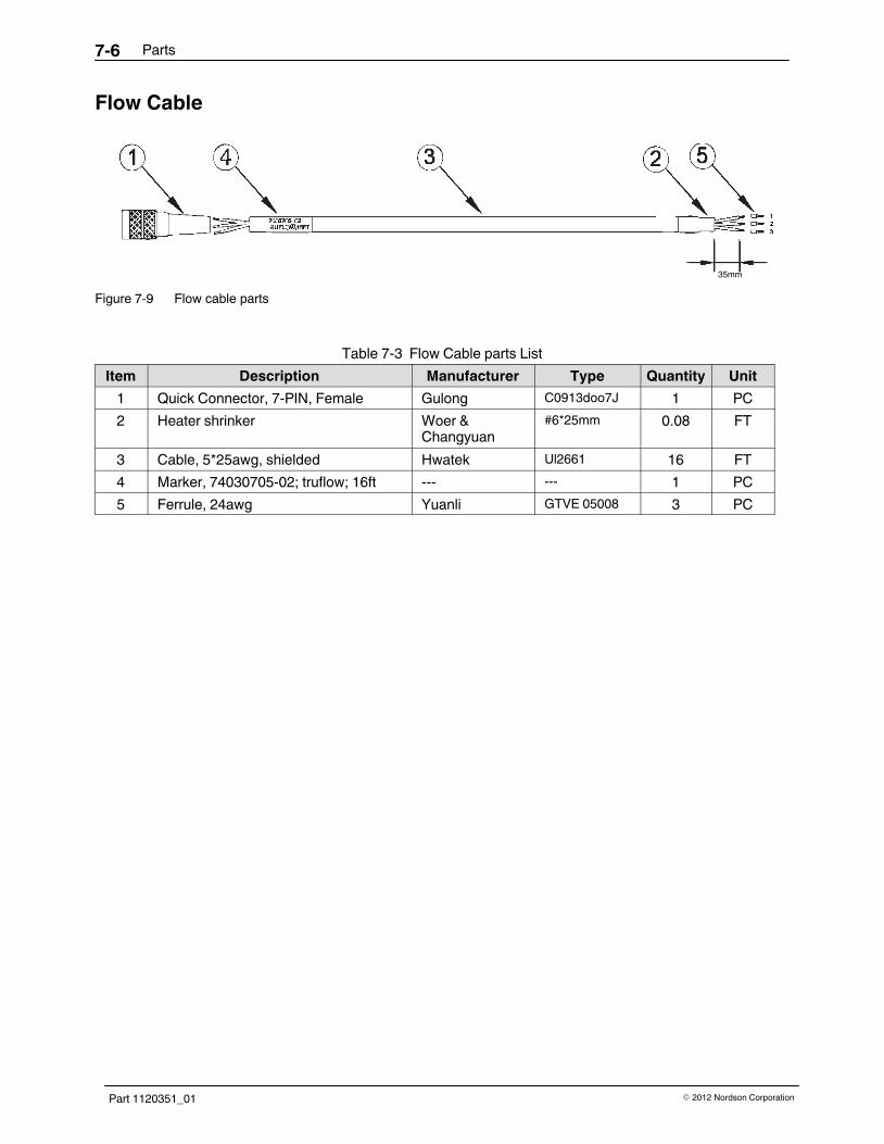
Parts7-6
Part 1120351_01 � 2012 Nordson Corporation
Flow Cable
35mm
Figure 7-9 Flow cable parts
Table 7‐3 Flow Cable parts List
Item Description Manufacturer Type Quantity Unit
1 Quick Connector, 7-PIN, Female Gulong C0913doo7J 1 PC
2 Heater shrinker Woer &Changyuan
#6*25mm 0.08 FT
3 Cable, 5*25awg, shielded Hwatek Ul2661 16 FT
4 Marker, 74030705-02; truflow; 16ft --- --- 1 PC
5 Ferrule, 24awg Yuanli GTVE 05008 3 PC

Parts 7-7
Part 1120351_01� 2012 Nordson Corporation
Pressure Build Control Parts
1006, 1007 and 1008
401, 402 and 403
1006, 1007 and 1008
1005
1004
10031001
1002
Figure 7‐3 Internal transducer parts

Parts7-8
Part 1120351_01 � 2012 Nordson Corporation
Table 7‐4 Internal transducer parts list
Item Part Description Quantity
401 7403137 KIT,FLOW/PRESSURE CONTROL BOARD 1
402 SCR,PAN,SLT,M3X6,ZN 4
403 WASHER,LK,M,INT,M3,STL,ZN 4
1001 TRANSDUCER,PRESSURE,M14X1.5, 0-1500PSI 1
1002 CABLE,PRESSURE,6 PIN,MELTER SIDE,TOUCH 1
1003 CLAMP,D26.5,TRANSDUCER,PRESSURE,ALUM 1
1004 SCR,SKT,M5X16,BL 1
1005 WASHER,LK,M,SPT,M5,STL,ZN 1
1006 MOUNT,SADDLE TIE, DIA.6 2
1007 NUT,HEX,M5,STL,ZN 2
1008 WASHER,FLT,M,REG,M5,STL,ZN 2

Parts 7-9
Part 1120351_01� 2012 Nordson Corporation
External Pressure Transducer Parts
Figure 7‐4 External transducer parts
Item Part Description Quantity
7403139 KIT,TRANSDUCER,APPLICATOR,4-20MA
7403140 KIT,TANSDUCER,APPLICATOR,0-10VDC
1 TRANSDUCER, MELT PRESSURE, 4-20mA 1
NS TRANSDUCER, MELT PRESSURE, 0-10 VDC 1
2 ADAPTER,WITH O-RING,TRANS,M16X1.5,L=30 1
NS ADAPTER,WITH O-RING,TRANS,M16X1.5,L=40 1

Parts7-10
Part 1120351_01 � 2012 Nordson Corporation
External Pressure Cable (4-20mA)
35mm
31
Figure 7-10 Pressure Cable (4−20mA) Parts
Table 7‐5 External Pressure Cable (4-20mA) Parts List
Item Description Manufacturer Type Quantity Unit
1 Quick Connector, 6-PIN, Female Souriau 851-06AC10-6S50
1 PC
2 Heater shrinker Woer &Changyuan
#6*25mm 0.08 FT
3 Cable, 5*25awg, shielded Hwatek UL2661 16 FT
4 Marker, 74030711-02: 4-20mA; 16 FT --- --- 1 PC
5 Ferrule, 24awg Yuanli GTVE 05008 4 PC

Parts 7-11
Part 1120351_01� 2012 Nordson Corporation
External Pressure Cable (0-10V)
35mm
1
234
Figure 7-11 Pressure Cable (0−10V) Parts
Table 7‐6 External Pressure Cable (0-10 V) Parts List
Item Description Manufacturer Type Quantity Unit
1 Quick Connector, 6-PIN, Female Souriau 851-06AC10-6S50
1 PC
2 Heater shrinker Woer &Changyuan
#6*25mm 0.08 FT
3 Cable, 5*25awg, shielded Hwatek UL2661 16 FT
4 Marker, 74030700-02: 0-10 V; 16 FT --- --- 1 PC
5 Ferrule, 24awg Yuanli GTVE 05008 4 PC

Parts7-12
Part 1120351_01 � 2012 Nordson Corporation
Recommended Spare Parts
Table 7‐7 Recommended Spare Parts - Kits
P/N Description
Flow/Pressure Control
7403139 KIT,TRANSDUCER,APPLICATOR,4-20MA
7403140 KIT,TRANSDUCER,APPLICATOR,0-10VDC
7403141 KIT,CABLE,0-10V,16FT,PRESSURE
7403142 KIT,CABLE,0-10V,24FT,PRESSURE
7403143 KIT,CABLE,0-10V,30FT,PRESSURE
7403146 KIT,TRUFLOW,T-STYLE,12MM,TRUEFLOW,MELTER
7403147 KIT,TRUFLOW,M-STYLE,12MM,TRUEFLOW,MELTER
7403148 KIT,CABLE,TRUFLOW,L-16FT W/6 PIN CONN
7403149 KIT,CABLE,TRUFLOW,L-24FT W/6 PIN CONN
7403150 KIT,CABLE,TRUFLOW,L-30FT W/6 PIN CONN
7403151 KIT,RVS 1 MELTER, 24FT,TOUCH
7403152 KIT,RVS 1-5 MELTER,50 FT,TOUCH
7403153 KIT,RVS 1-5 MELTER,100FT,TOUCH
7403154 KIT,CABLE,4-20mA,16FT,PRESSURE
7403155 KIT,CABLE,4-20mA,24FT,PRESSURE
7403156 KIT,CABLE,4-20mA,30FT,PRESSURE
Table 7‐8 Recommended Spare Parts - Hoses
Hose Size Fitting PartNumber
Fitting Type Fitting Size,Melter Size
Fitting Size Hose Size
8-mm 7400333 Straight
M16x1.5
7400337 45-degree
7400335 90-degree
12-mm 7401279 Straight
7401278 45-degree
7401277 90-degree
16-mm 7400334 Straight M22x1.5
7400338 45-degree
7400336 90-degree

