flow fields and droplet dynamics of turbulent spray flames ......experiment and diagnostics i. the...
TRANSCRIPT

Flow fields and droplet dynamics of turbulent spray flames in curved wall jet burner
M. S. Mansour1,2*
, I. Alkhesho1, G. Scribano
1, H. Mitsudharmadi
1, F. Bisetti
1, S. H. Chung
1
1Clean Combustion Research Center, King Abdullah University of Science and Technology, Thuwal
23955-6900, Kingdom of Saudi Arabia 2Department of Mechanical Engineering, Helwan University, Cairo, Egypt
ABSTRACT
A curved wall jet (CWJ) burner was employed to stabilize turbulent spray flames that utilize a Coanda effect; air is
supplied as an annular-inward jet over a curved surface, surrounding an axisymmetric solid cone fuel spray. Flow
velocity fields of the oxidizer and droplet size and velocity data were measured using Stereoscopic Particle Image
Velocimetery (SPIV) and a Phase Doppler Interferometer (PDI) system, respectively. SPIV measurements revealed
that the general features of the flow field exhibit typical flow characteristics of the CWJ burner. As the air flow rate
increases, the droplets size (D32) decreases upstream at off-center positions and becomes more uniform in the radial
direction. Moreover, the mean axial droplets velocity reduces in the near-field flow of flames.
Introduction
Combustion of liquid fuel sprays impacts a variety
of practical combustion devices such as gas turbines,
compression-ignition engines, industrial furnaces and
boilers [1]. Understanding the physical phenomena that
control spray combustion processes is desirable, as most
of these devices utilize the fuel in a two-phase flow.
Phenomena such as flame stabilization, structure, and
extinction are important aspects of spray flames that are
not well understood across the wide variety of
combustion systems. The mutual interaction of the spray
and flow field can play an important role in determining
the dominant mechanisms controlling flame behaviour
i.e. flame stabilization and structures [2], It is
well-recognized that such interaction determines
combustion efficiency and pollutant emissions [3].
There have been extensive experimental and
numerical studies on turbulent spray combustion in
different configurations [4]. The spray burner being
investigated uses the Coanda effect [5] to create a
configuration that improves flame stabilization and
enhances droplet evaporation in the near-injector region.
In a previous turbulent premixed flame study with the
same burner [6], a mixture of propane/air was injected
over a curved wall as a form of annular-inward jet. Due
to the curvature of the streamlines, a low-pressure
region was generated, resulting in flow adherence to the
curved surface. As the static pressure recovered, the
wall-jet separated to form a recirculation zone (RZ). The
annular-inward jet collided over the RZ in an interaction
jet region, generating a high level of turbulence by the
collision as well as the effect of ambient air
entrainment; this was subsequently developed as a
merged jet in the downstream region. Such burner
resulted in improved flame stabilization and a shorter
flame length. Kim et al. [7] further improved premixed
flame stabilization by modifying the burner with a
cavity.
We propose a new burner concept that utilizes the
aforementioned Coanda effect to stabilize turbulent
spray flames. This was achieved by using a liquid fuel
(n-heptane) that was injected through the spray nozzle at
the centre of the burner as shown in Fig. 1. The
evaporation of the liquid fuel is significantly augmented
due to the following: (1) The recirculated hot gases
upstream enhance droplet evaporation significantly; (2)
the air flow in the interaction jet region disperses the
droplets; (3) the air entrainment associated with
reactants or air flow dilutes the spray with oxidizer; (4)
the steep velocity gradient, formed along the curved
wall, enhances the interaction between the air and
droplets.
Application of PIV [9] and PDI [10] techniques
contributed to better understanding of spray–flow
interaction. A turbulent ethanol spray flame was
characterized using PDA in [11] in terms of droplet size
and velocity. A comprehensive mapping of the flow and
droplet fields in turbulent non-reacting and reacting
dilute spray jets of acetone and ethanol fuels was
presented in [12] utilizing an LDV/PDA setup. The flow
field and droplet dynamics of spray flames were
characterized using PIV and PDI measurements,
respectively.
In the present study, we investigated the
flow-spray-flame interactions close to the injection
point of the burner with detailed spatial and temporal
measurements using high-speed laser diagnostic
techniques. Multi kHz stereo particle image velocimetry
(SPIV) and Phase Doppler Interferometer (PDI)
techniques were used to provide insight on turbulent
non-reactive flow field and spray characteristics,
respectively. This extensive database of high-resolution
measurements is also required for turbulent spray
combustion modelling.
L
31
r
y
Z
Nozzle
Air slit
Air Air
Liquid fuel
Figure 1 CWJ burner, all dimensions are
in mm, L = 5, 20 mm.
* Corresponding author: [email protected]
Proceedings of the European Combustion Meeting 2015
2
Experiment and Diagnostics
I. The curved-wall jet burner
The CWJ burner (Fig. 1) is composed of an inner
hollow cylinder with 70 mm in diameter and 150 mm in
length, having a hemi-spherical end. On the top, the
cavity has a width of 31 mm. A pressure assisted fuel
injector (Danfoss) is inserted along the burner centreline.
The distance from the injector tip to the burner exit
plane, L, can be controlled, altering the residence time
of the droplets inside the inner hollow cylinder and the
flow-field-spray interaction region. In the present study,
two values of L are investigated: 5 and 20 mm. The
Danfoss solid cone nozzle is characterized by a 60°
cone angle and 0.23 mm orifice. An outer flow guide
has a concentric cylinder with 72 mm i.d.; this forms a
converging section with an exit diameter of 56 mm and
R = 36 mm. This converging section enables the
velocity field to be directed tangentially into the curved
surface then oriented toward the burner axis. This
annular-inward jet collides in the jet interaction region,
generating a high level of turbulence. We modified the
dimensions of the concave cavity compared to [7] in
order to accommodate a larger recirculation zone (RZ). The burner was mounted onto a 3D stepper
motor-controlled traverse system that provides a spatial
resolution of 0.62 mm.
Air was metered using mass flow controllers
(BROOKS INSTRUMENT) and supplied through the
curved-wall slit. Liquid fuel (>99% pure n-heptane) is
supplied from a pressurized tank. The injection fuel
pressure is varied between 4 and 11 bar. This
corresponds to a fuel flow rate of 0.81 and 1.39 kg/hr.
Details of test conditions are listed in Table 1. Case L5
(L20) marks the flame in which the pressure nozzle was
placed at 5 (20 mm) upstream of the annular air jet as
shown in Fig. 1. �̇�𝑎𝑖𝑟 is the air flow rate and �̇�𝑓 is the
fuel mass flow rate that is kept constant in the current
study at 1.247 kg/hr corresponding to 9 bar fuel pressure.
is the liquid fuel equivalence ratio The characteristic
Reynolds number, Re= deff V0/a, is based on the mean
jet velocity, V0, the kinematic viscosity of air, a, calculated from Gaseq code [13] and the effective
diameter, deff, defined as deff = (4A0)⁄π)0.5
, where A0 is
the exit area at the slit, which is calculated from the
normal projection from the tip of the outer cylinder to
the inner one. The exit area was kept constant at 200
mm2 in the present study and Re ranges from 0 to 17520.
Several parameters in Table 1 will be further discussed
later.
Table 1 Details of experimental conditions.
Case �̇�𝑎𝑖𝑟
[Lpm]
�̇�𝑓
[kg/hr] ∅ 𝑅𝑒
L5-1 0
1.247
- 0
L5-2 60 4.32 5256
L5-3 200 1.30 17519
L20-1 0 - 0
L20-2 60 4.32 5256
L20-3 200 1.295 17519
II. Stereoscopic Particle image velocimetry (SPIV)
The SPIV system (LaVision, LDY 300) consistes of
a high-repetition rate (up to 10 kHz) twin-cavity
diode-pumped Nd:YLF laser (Litron, LDY304-PIV at
527 nm, 28 mJ/pulse, 5 ns pulse duration) and two
CMOS cameras (LaVision, Imager Pro HS 4M with
2016×2016 pixels) coupled with a high speed controller.
A laser sheet of about 1 mm thickness and 90 mm
height was formed using two cylindrical lenses. A time
separation of 30 to 50 µs was used at 2.5 kHz,
producing 3D vector fields every 0.4 ms.
Seed particles were TiO2 having 0.18 µm nominal
diameter. Seed levels were adjusted for accurate vector
computation and maintained the number of spurious
vectors during image processing below 5%. The Mie
scattered light from each laser pulse was recorded on a
separate frame. The two cameras were placed
equidistant from, and on the same side of, the laser sheet
to collect forward and backward scattered light at an
angle of 40° with the laser sheet plane. The Scheimpflug,
mounts had an angle of 5-7° to project the focus plane
onto the target frame. Two different apertures were used
to match recorded light intensity for the two cameras to
compensate for the intensities of the forward and
backward scattered light. Distortion from the camera
system was remedied by imaging a 3-D dot target
(LaVision type 11).
The velocity vector fields were determined through a
multi-pass vector computation technique (LaVision
Davis 8.1 software) with interrogation region size of 32
× 32 pixels having 50% overlap, equivalent to a spatial
resolution of 1.1 × 1.1 mm. The system was operated at
2.5 kHz and 0.2 s of flow times were recorded such that
500 double-frame images were analyzed.
III. Phase Doppler Interferometer (PDI)
A 2D Phase Doppler Interferometer (PDI) system
was used to characterize spray droplets size and velocity
distributions as well as the number density. The system
measures the velocities in z and r coordinates shown in
Fig. 1. The PDI allows the simultaneous measurement
of droplet velocity and size, where the droplet size is
determined based on the measured phase shift difference
between two Doppler bursts whilst the droplet velocity
is derived from the Doppler burst frequency. The PDI
system (model 300 MD, Artium Technologies) consists
of a continuous solid laser that produces two continuous
laser beams at 532 and 491 nm. The former has 350
mW power to measure the axial velocity component
(Vz) and droplet size, while the latter has 100 mW
power to measure the radial velocity component (Vr).
Four beams were split and focused by a 150 mm focal
length lens to form a measurement probe volume. The
light scattered from droplets passing through the
measurement volume was captured by the receiving
optics positioned at =45° off axis in the forward
scattering mode to maximize the collection of light as
shown in Fig. 2. The focal length of the receiving optic
was 350 mm.

3
Figure 2 Schematic of the PDI.
Three photomultiplier detectors are lined up and
are maintained at a fixed separation from each other.
The three photomultiplier tubes convert the three light
signals from the three detectors into three electronic
signals that are processed to extract velocity and size
information. The signals from the photomultipliers are
post processed by 2 ASA post processors. One processor
is used for the z component of the velocity and size,
whereas the other processor is used for the r component
of the velocity. The measured size is corrected for the
probe volume correction according to the Gaussian
beam effect [14]. The droplets size statistics are based
on the corrected size distribution.
Results and Discussion
I. Non-reacting flow field characteristics
The SPIV system was used to characterize the
turbulent flow field for a non-reacting condition. A
coordinate system is adopted in representing data with
(r,z,y) in the radial, axial and normal coordinates,
respectively, with z=0 at the tip of the cavity (Fig. 1).
Data collected from 500 images at 2.5 kHz were
analyzed and the mean velocities (𝑉𝑟 , 𝑉𝑧, 𝑉𝑦) and rms
velocities (𝑉𝑟′, 𝑉𝑧
′, 𝑉𝑦′) in the radial, axial and normal
coordinates, respectively, were determined. The spatial
distributions of ( 𝑉𝑟 , 𝑉𝑧 ), together with color-coded
magnitude of 𝑉𝑦 are shown in Fig. 3 for the
non-reacting flow conditions that mimic cases
(L5-2(L20-2), L5-3(L20-3)).
The non-reacting flow field exhibits flow
characteristics similar to those of the CWJ burner. The
flow field consists of a recirculation zone (RZ), an
interaction jet (IJ) region with the collision of the
annular-inward jets near z=10 mm, and a downstream
merged jet (MJ) region. Inner and outer shear layers
(ISL and OSL) surrounding the annular-inward jets (AJ)
can also be identified as shown in Fig. 3.
The axial (at r=0) and radial (at z=4 mm) profiles of
the mean and rms velocities are plotted in Fig. 4 for the
non-reacting flow conditions that correspond to Fig. 3.
The recirculation zone is clearly exhibited by 𝑉𝑧 having
negative values for 0<z<10 mm (Fig. 4a), which
approaches 4 m/s (case L5-3 or L20-3). In the
interaction jet region, 𝑉𝑧 increases rapidly and then
decreases slightly up to z=90 mm in the merged jet
region. 𝑉𝑟 exhibits higher values near z=15 mm in the
interaction jet region. However, cases L5-1 or L20-1
reveal negligible value of 𝑉𝑟 (see Fig. 4b).
Figure 3 Spatial distribution of mean velocity fields
with the background color indicating the y-velocity
component for the non-reacting flow conditions
corresponding to L5-2(L20-2) and L5-3(L20-3) cases.
Figure 4 Axial 𝑉𝑧 (a), 𝑉𝑟 (b), 𝑉𝑧
′ (c) 𝑉𝑟′ (d) and radial
𝑉𝑧 (e), 𝑉𝑟 (f), 𝑉𝑧′ (g) 𝑉𝑟
′ (h) profiles of mean and rms
velocities for the cases in Fig.3.
The axial profiles of rms velocities (Figs. 4c, and 4d)
show that 𝑉𝑟′ is high in the RZ and reaches its
maximum in the interaction jet region, while it is
spatially uniform in the merged jet region. 𝑉𝑧′ is
spatially homogeneous also. These results indicate that
the collision of annular-inward jet near the boundaries
of RZ influences the generated turbulence.
Burner
Z r
𝑉𝑦 m/s
RZ
IJ
MJ
AJ OSL
ISL
L5-2
(L20-2)
L5-3
(L20-3)

4
The radial profiles of 𝑉𝑧 (Fig. 4e) at z=4 mm again
exhibit RZ (negative values), inner and outer shear
layers (large velocity gradient), and annular-inward jets.
𝑉𝑧 and 𝑉𝑟 peak near r=15 mm in the annular jet region.
𝑉𝑟 decreases at the centreline and in the outer shear
layer.
The outer shear layer plays a more important role
than the inner shear layer in generating high values of
all rms velocity components, particularly in high Re
flames as shown in Fig. 4(g). However, 𝑉𝑟′ exhibits
relatively high values at r=0 in case L5-3 (L20-3) due to
the collision of the annular-inward jets. These rms
velocities are expected to be influenced significantly by
the heat release in reacting flames [15].
II. Droplets velocity and size in flames
The radial profiles of axial and radial mean
velocities (left axis) of n-heptane fuel droplets for
reacting cases L5-1 and L5-3 are shown in Fig. 5 at two
different axial locations (z=4, 12 mm). The
corresponding rms velocities are shown on the right axis.
These values for case L20 are shown in Fig. 6. It is
shown that the profiles of the mean axial velocity of the
droplets in the near-field flow of n-heptane flames is
slightly (significantly) lower than in the spray without
annular air for L = 5 mm (L=20 mm). In flames without
the air jet, droplets exhibited higher values of velocities
because there is no a recirculated flow; however, as we
introduced the annular air jet, the droplets display low
and even negative velocities at the centerline that is
reversed near the spray-air shear layer for case L5. The
peak axial and radial droplet velocities shown in Figs. 5
and 6 are lower than the corresponding local mean gas
velocities close to the centerline reported in Fig. 4. This
is attributed to the drag effect on the droplets by the
recirculated gases momentum. RMS velocity
components exhibit higher values with air particularly
downstream of flame L20-3. Values of 𝑉𝑟′ and 𝑉𝑧
′
increase radially and have high magnitudes within the
shear layers.
The Sauter mean diameter (D32), representing the
droplet size, is shown in Fig. 7 under reacting
conditions for cases L5-1(L20-1) and L5-3 (L20-3). The
mean droplet sizes generally increase radially due to
droplet inertia augmented by the created flow field; such
trend is consistent with previous results in a swirling
spray flame [16]. The series of cases L20 show lower
droplet sizes since further downstream from the spray
injection point, the effect of evaporation and reaction on
droplet sizes is more pronounced. The annular air-jet
influences significantly the droplet size, particularly
within both the recirculation zone and the interaction jet
region. As the air flow rate increases, the droplets size
decreases upstream at off-center positions; such effect is
less apparent toward the burner centerline. Along the
centerline, the effect is reversed. As L increases, the
droplets size becomes more uniform moving outward
radially, particularly downstream (z=12 mm); similar
trends are observed for the cases L5 upstream (z=4
mm).
Figure 5 Radial profiles of droplet axial and radial mean
velocities (left) and the corresponding rms values (right)
for two different heights (z) of cases L5-1 and L5-3.
Figure 6 Radial profiles of droplet axial and radial mean
velocities (left) and the corresponding rms values (right)
for two different heights (z) of cases L20-1 and L20-3.
Figure 7 Radial profiles of D32 for two different heights
(z) of cases L5-1 (L20-1) and L5-3 (L20-3).
III. PDFs of droplets in flames
Although droplet mean velocities and D32 provide
information on the overall interaction of the n-heptane
spray with the annular air flow field, no information is
provided on the dynamics of individual droplets. Such
information is obtained in the form of the velocity
distribution and droplet size pdfs. The radial profiles of
probability density functions (pdfs) of the velocity
distributions for flames L5-1, L5-3, L20-1 and L20-3
are shown in Figs. 8 and 9 at z=4 mm while the axial
5
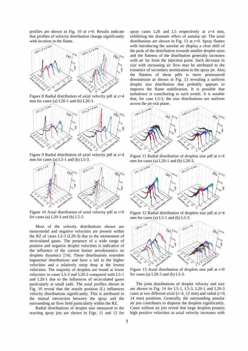
profiles are shown in Fig. 10 at r=0. Results indicate
that profiles of velocity distribution change significantly
with location in the flame.
Figure 8 Radial distribution of axial velocity pdf at z=4
mm for cases (a) L20-1 and (b) L20-3.
Figure 9 Radial distribution of axial velocity pdf at z=4
mm for cases (a) L5-1 and (b) L5-3.
Figure 10 Axial distribution of axial velocity pdf at r=0
for cases (a) L20-3 and (b) L5-3.
Most of the velocity distributions shown are
monomodal and negative velocities are present within
the RZ of cases L5-3 (L20-3) due to the momentum of
recirculated gases. The presence of a wide range of
positive and negative droplet velocities is indicative of
the influence of the current burner aerodynamics on
droplets dynamics [14]. These distributions resemble
lognormal distributions and have a tail to the higher
velocities and a relatively steep drop at the lowest
velocities. The majority of droplets are found at lower
velocities in cases L5-3 and L20-3 compared with L5-1
and L20-1 due to the influences of recirculated gases
particularly at small radii. The axial profiles shown in
Fig. 10 reveal that the nozzle position (L) influences
velocity distributions significantly. This is attributed to
the mutual interaction between the spray and the
surrounding air flow field particularly within the RZ.
Radial distributions of droplet size measured in the
reacting spray jets are shown in Figs. 11 and 12 for
spray cases L20 and L5 respectively at z=4 mm,
exhibiting the dramatic effect of annular air. The axial
distributions are shown in Fig. 13 at r=0. Spray flames
with introducing the annular air display a clear shift of
the peak of the distribution towards smaller droplet sizes
and the flatness of the distribution generally increases
with air far from the injection point. Such decrease in
size with increasing air flow may be attributed to the
existence of secondary atomization in the spray jet. Also,
the flatness of these pdfs is more pronounced
downstream as shown in Fig. 13 revealing a uniform
droplet size distribution that probably appears to
improve the flame stabilization. It is possible that
turbulence is contributing to such trends. It is notable
that, for case L5-3, the size distributions are uniform
across the jet exit plane.
Figure 11 Radial distribution of droplets size pdf at z=4
mm for cases (a) L20-1 and (b) L20-3.
Figure 12 Radial distribution of droplets size pdf at z=4
mm for cases (a) L5-1 and (b) L5-3.
Figure 13 Axial distribution of droplets size pdf at r=0
for cases (a) L20-3 and (b) L5-3.
The joint distributions of droplet velocity and size
are shown in Fig. 14 for L5-1, L5-3, L20-1 and L20-3
cases at two different axial (z=4, 12 mm) and radial (r=0,
14 mm) positions. Generally, the surrounding annular
air jets contributes to disperse the droplets significantly.
Cases without air jets reveal that large droplets possess
high positive velocities as axial velocity increases with

6
the droplet size. However, introducing annular air
around the spray improved the evaporation/atomization
of large droplets as large droplets disappear (see Fig.
14) particularly for L20 cases.
At z=4 mm, air jets reduce the velocities of small
droplets and numerous droplets are recirculated within
the recirculation zone as shown in Fig. 14 (upper row).
However, at z=12 mm, droplets are located within the
interaction jet region, which contributes to disperse
droplets with positive axial velocities particularly at
r=14 mm. Again the droplet size increases with the
radial position for cases without air jets. The number
density of the droplets for flame L5-1 is low at r=14 mm
and z=4 mm; however, introducing the annular air jets
disperses these droplets radially increasing the number
of droplets through the PDI probe volume.
Figure 14 Droplet size-velocity correlation at two
different radial (r=0, 14 mm) and axial (z=4 and 12 mm)
spatial positions for flames L5-1, L5-3, L20-1 and
L20-3.
Conclusions
The interaction of spray and air stream in n-heptane
turbulent spray nonpremixed flames was investigated to
obtain a comprehensive mapping of the flow and droplet
fields in turbulent non-reacting jets and reacting spray
flames. A curved wall jet (CWJ) burner was employed
to stabilize turbulent spray flames. The burner utilized a
Coanda effect by supplying air as annular-inward jet
over a curved surface, surrounding an axisymmetric
solid cone fuel spray. Stereoscopic particle image
velocimetery (SPIV) quantified the flow field features
while phase Doppler interferometer (PDI) was used to
characterize droplet dynamics. We investigated the
effects of increasing the oxidizer (air) flow rate at a
fixed liquid flow rate and the position of fuel atomizer
with respect to the annular-inward jet (L) on the spray
characteristics. SPIV measurements revealed that the
general features of the flow field exhibit typical flow
characteristics of the CWJ burner; a recirculation zone
(RZ) near the cavity exit, an interaction jet (IJ) region
with the collision of the annular-inward jets near z =10
mm, and a downstream merged jet (MJ) region. Also,
high turbulent rms velocities were generated within the
recirculation zone, which improved the flame
stabilization. As the air flow rate increased, the droplets
size decreased remarkably upstream at off-center
positions; such effect diminished toward the burner
centerline and finally was reversed along the spray
centerline. It is also found that as the annular air jet is
supplied, large droplets are vaporized/atomized and then
dispersed. As L increases, the droplets size becomes
radially more uniform. It is shown that the profiles of
the mean axial droplets velocity in the near-field flow of
n-heptane flames is slightly (significantly) lower than in
spray without annular air for L = 5 mm (L=20 mm).
References
[1] Faeth, G. M., Prog. Energy Combust. Sei. 13
(1987) 293-345.
[2] Faeth, G. M., Prog. Energy Combust. Sei. 9 (1983)
1-76.
[3] Lefebvre, A. H., American Institute of Aeronautics
and Astronautics, 12 (1984) 887-898.
[4] Faeth, G. M., “Spray combustion phenomena”,
Proc. Comb. Inst. 26 (1996) 1593–1612.
[5] Gregory-Smith, D. G., Hawkins, M. J., Int. J. Heat
and Fluid Flow, 12 (1991) 323-330.
[6] Gil, Y. S., Jung, S. H., Chung, S. H., Combust.
Flame, 113 (1998) 348-357.
[7] Kim, D., Gil, Y. S., Chung, T. W., Chung, S. H.,
Combust. Sci. and Tech. 181 (2009) 1397-1412.
[8] Kohse-Höinghaus, K., Jeffries, J., Applied
Combustion Diagnostics, Taylor & Francis, New
York, 2002.
[9] Chong C.T. and Hochgreb S., Fuel 115 (2014)
551-558.
[10] Strakey, P. A., Talley, D. G., Sankar, S. V., and
Bachalo, W. D., Applied Optics, Vol. 39 (2000) No.
22.
[11] Duwel, I., Ge, H.-W., Kronemayer, H., Dibble, R.,
Gutheil, E., Schulz, C., Wolfrum, J., Proc.
Combust. Inst. 31 (2007) 2247-2255.
[12] Gounder, J. D., Kourmatzis, A., Masri, A. R.,
Combust. Flame, 159 (2012) 3372–3397.
[13] Morley C., Gaseq chemical equilibrium program
available at: [email protected]
[14] Bachalo, W. D. and Houser, M. -J. AIAA-84-1199
(1984).
[15] Hartung, G., Hult, J., Kaminski, C. F., Rogerson, J.
W., Swaminathan, N., Physics of Fluids, 20 (2008)
035110.
[16] Presser C., Gupta A. K., Semerjian H. G., Combust.
Flame 92 (1993) 25–44.
Ax
ial
vel
oci
ty, V
z [m
/s]
Diameter [m]