floor warming and heating systems - flextherm.asia · 2 green cable surfaceinstallation guide and...
TRANSCRIPT

Floor Warming and Heating Systems
INSTALLATION GUIDE
SPREAD THE WARMTH

Green Cable Surface Installation Guide
1Green Cable Surface Installation Guide
Floor Surface PreparationGeneral InstructionsThe Green Cable Surface can be installed on a multitude of sub-floors!
IMPORTANT: the sub-floor must meet construction standards and be strong enough to support ceramic tile, natural stone or self-levelling underlayment.
Always check with the sub-floor material manufacturer to ensure compatibility with floor heating systems. Whatever the selected support, the floor surface must be clean, flat, smooth and free of protruding nail or screw heads or other materials that may damage the cables. Always ensure that the selected sub-floor is compatible with mortars or self-levelling underlayments.
Compatible Sub-floors Insulation Board and Thermal Barrier FLEXTHERM does strongly recommend to install an insulation board or a thermal barrier over the concrete slab in order to optimize the effiency of the system. The cable should be installed on top of the insulation.
Smooth Concrete SlabWe recommend that the FLEXTHERM floor heating system be installed on an insulated concrete slab to avoid energy loss caused by a non-insulated thermal mass affected by elements. When a concrete slab is chosen as the sub-floor, we recommend that all the rooms the slab supports be heated with a FLEXTHERM floor warming and heating system to avoid heat loss on the perimeter. Otherwise, the performance of the system could be compromised.
Mortar BedThe Green Cable Surface and the floor probe can be installed on top of the mortar bed or under it, if its thickness is less than 50 mm (2 in) and sand is the only aggregate. To ensure the adhesion of the installation gauges on the mortar bed, the mortar bed must be smoothed with a flat trowel in order to obtain a surface that is smooth and uniform, not granular. Should the surface be too granular for the hot glue, glaze the mortar bed with thinset mortar.
Existing Ceramic or Stone TileRefer to the mortar or self-levelling underlayment manufacturer to adequately prepare the sub-floor to ensure proper adhesion. As long as the existing ceramic tile or stone floor is well-bonded to the subfloor, FLEXTHERM Green Cable Surface can be installed over it. Be aware that if there is no insulation under the existing floor, the performance of the system could be compromised.
Anti-fracture MembraneThe heating cable is generally installed over the membrane. However, certain manufacturers recommend that the cable be installed under the membrane. Always check with the manufacturer before proceeding with the installation.
Acoustic MembraneInstall the membrane following the manufacturer recommendations. The heating cable is to be installed over the membrane, which must be properly glued to the sub-floor prior to installing the cable. Validate with the manufacturer that the membrane is compatible with electric floor heating systems.
Plywood and Cement Board
FLEXTHERM Floor Warming and Heating Systems are installed directly on a plywood surface or cement board without any specific floor preparation, other than the general instructions mentioned previously.
Congratulations, you are now a FLEXTHERM Floor Warming & Heating System owner. To ensure the best possible installation, please read the following guide before you begin. Ensure that the installation is in accordance with the local and/or national electric codes.
This product is designed to be installed at a regular spacing of 7.6 cm (3 in) or 10 cm (4 in) according to cable output and heating requirements. Under no circumstances can the spacing be modified during the installation. Refer to the “Cable Installation” section of this guide to confirm the appropriate spacing for your installation.
This product can be used as a main source of heating (provided the heat loss of the room falls below the energy installation capabilities) or as an added touch of comfort at your feet. The ambient and floor temperatures that can be achieved are dependent on the insulation of the room, window coverage, type of floor covering used, etc. To learn more about the performance of the system for your particular installation, refer to the construction professional (architect, engineer) that manages your project.
This system is designed and approved for interior room heating in wet or dry environments, subject to local electrical standards.
For any additional information, please consult your authorized FLEXTHERM dealer.
CAUTION: Do not use in areas subject to high mechanical loads or impact.
Heating Cable, Class M1This cable is an electrical appliance and should be installed according to the local and/or national electrical codes. Its installation should be entrusted to duly qualified personnel where required by law.
Required Materials and Tools In order to install the system, you will need the following items: 1. FLEXTHERM Floor Warming and Heating Cable kit including: heating
cable, gauges, glue sticks and installation guide. 2. FLEXTHERM thermostat and floor probe, sold separately.3. Hot glue gun.*4. Expanded electrical connection box.6. Appropriate multimeter. 7. Megohmmeter.8. Various tools: measuring tape; marker; calculator; screw driver; tool to
groove the sub-floor; fish cords (to raise the cables in the wall); shears, electrical tape; a 2.5 cm (1 in) diameter and 30 cm (1 ft) long stick or pipe for the dispenser box.
9. Vacuum cleaner, broom, pail of water and sponge.10. Cardboard or other light material (to put the tools on).
* The gauges can be secured to the sub-floor by using the supplied hot glue sticks.
Note: Do not staple the cable itself.
YOUR SAFETY IS IMPORTANT TO US
This guide contains instructions regarding safety as well as precautions to take to ensure a compliant and successful installation. Please pay special attention to this symbol and follow any instruction given.
2 Green Cable Surface Installation Guide
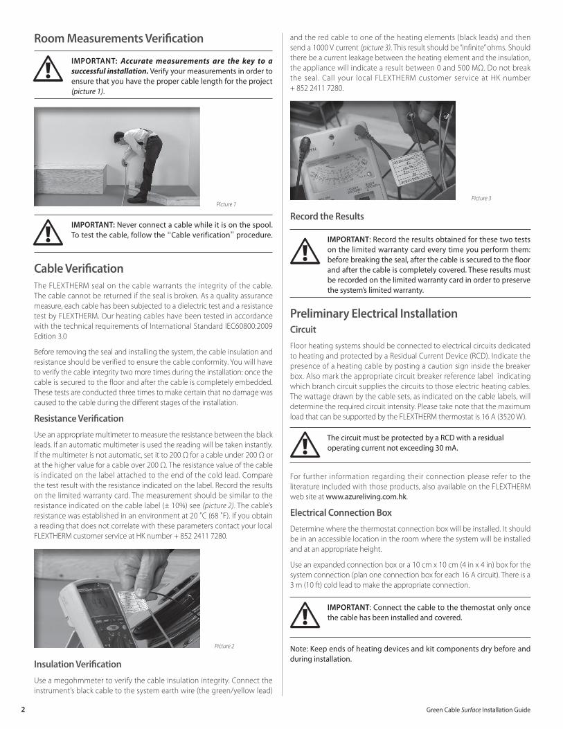
and the red cable to one of the heating elements (black leads) and then send a 1000 V current (picture 3). This result should be “infinite” ohms. Should there be a current leakage between the heating element and the insulation, the appliance will indicate a result between 0 and 500 MΩ. Do not break the seal. Call your local FLEXTHERM customer service at HK number + 852 2411 7280.
Picture 3
Record the Results
IMPORTANT: Record the results obtained for these two tests on the limited warranty card every time you perform them: before breaking the seal, after the cable is secured to the floor and after the cable is completely covered. These results must be recorded on the limited warranty card in order to preserve the system’s limited warranty.
Preliminary Electrical InstallationCircuit
Floor heating systems should be connected to electrical circuits dedicated to heating and protected by a Residual Current Device (RCD). Indicate the presence of a heating cable by posting a caution sign inside the breaker box. Also mark the appropriate circuit breaker reference label indicating which branch circuit supplies the circuits to those electric heating cables. The wattage drawn by the cable sets, as indicated on the cable labels, will determine the required circuit intensity. Please take note that the maximum load that can be supported by the FLEXTHERM thermostat is 16 A (3520 W).
The circuit must be protected by a RCD with a residual operating current not exceeding 30 mA.
For further information regarding their connection please refer to the literature included with those products, also available on the FLEXTHERM web site at www.azureliving.com.hk.
Electrical Connection Box
Determine where the thermostat connection box will be installed. It should be in an accessible location in the room where the system will be installed and at an appropriate height.
Use an expanded connection box or a 10 cm x 10 cm (4 in x 4 in) box for the system connection (plan one connection box for each 16 A circuit). There is a 3 m (10 ft) cold lead to make the appropriate connection.
IMPORTANT: Connect the cable to the themostat only once the cable has been installed and covered.
Note: Keep ends of heating devices and kit components dry before and during installation.
Room Measurements Verification
IMPORTANT: Accurate measurements are the key to a successful installation. Verify your measurements in order to ensure that you have the proper cable length for the project (picture 1).
Picture 1
IMPORTANT: Never connect a cable while it is on the spool. To test the cable, follow the “Cable verification” procedure.
Cable VerificationThe FLEXTHERM seal on the cable warrants the integrity of the cable. The cable cannot be returned if the seal is broken. As a quality assurance measure, each cable has been subjected to a dielectric test and a resistance test by FLEXTHERM. Our heating cables have been tested in accordance with the technical requirements of International Standard IEC60800:2009 Edition 3.0
Before removing the seal and installing the system, the cable insulation and resistance should be verified to ensure the cable conformity. You will have to verify the cable integrity two more times during the installation: once the cable is secured to the floor and after the cable is completely embedded. These tests are conducted three times to make certain that no damage was caused to the cable during the different stages of the installation.
Resistance Verification
Use an appropriate multimeter to measure the resistance between the black leads. If an automatic multimeter is used the reading will be taken instantly. If the multimeter is not automatic, set it to 200 Ω for a cable under 200 Ω or at the higher value for a cable over 200 Ω. The resistance value of the cable is indicated on the label attached to the end of the cold lead. Compare the test result with the resistance indicated on the label. Record the results on the limited warranty card. The measurement should be similar to the resistance indicated on the cable label (± 10%) see (picture 2). The cable’s resistance was established in an environment at 20 ˚C (68 ˚F). If you obtain a reading that does not correlate with these parameters contact your local FLEXTHERM customer service at HK number + 852 2411 7280.
Picture 2
Insulation Verification
Use a megohmmeter to verify the cable insulation integrity. Connect the instrument’s black cable to the system earth wire (the green/yellow lead)
3Green Cable Surface Installation Guide
Cold Lead
The cold lead is the non-heating portion of the cable that will run in the wall to connect the system to the thermostat. The cold lead is flat and black and is connected to the heating cable with a mechanical joint. Just like the heating cable, the mechanical joint must be installed on the floor and covered with the selected mortar or self-levelling underlayment. Since the joint’s diameter is bigger than the heating cable’s, it may be necessary to insert it into a groove in the sub-floor in order to avoid unevenness when the floor covering will be installed.
Determine and mark the location where the mechanical joint will be fastened to the sub-floor. With the appropriate tools, make a 6 mm (1/4 in) groove on the sub-floor. Remove all debris caused by this operation to avoid potential damages to the cable. Using the hot glue supplied, secure the cable’s mechanical joint into the groove (picture 4). In a multiple cable installation, repeat these steps for each cable installed.
Picture 4
Cable Installation
IMPORTANT! Installation guidelines prior to installation, take note that…• The cable will be installed at a minimum distance of:
- 13 to 25 mm (1/2 to 1 in) from the base (kickplate) of a counter/cabinet, fixed furniture, steps, patio doors, baths or showers;
- 5 cm (2 in) from any walls; - 15 cm (6 in) from toilet drains; - 20 cm (8 in) from any other heating system, floor or wall
mounted (this does not apply to a convection type of heating appliance)
• The cable must be spaced at least 13 mm (1/2 in) from any exposed combustible surface.
• The cable cannot be overlapped, crossed, cut, shortened nor modified.
• The spacing between the cable runs must remain unchanged throughout the installation.
• Cables must be installed in runs lesser than 3 m (10 ft). Divide the room in smaller sections, should your room exceed 3 m (10 ft).
• FLEXTHERM Universal Snap-in Gauges™ are the only approved anchoring device. The use of any other anchoring method (e.g. staples or nails) will immediately void the warranty.
• The minimum bending radius of the cable is 13 mm (1/2 in).• All the heating portion of the cable (including the
mechanical joint) must be secured to the floor and covered with mortar or self-levelling underlayment. The heating cable should never be, under any consideration, installed in/on or under walls.
• The system should not be installed under fixed furniture or where air does not flow freely. It should never be installed in closets, over walls or partitions nor over cabinets.
• The heating cable should never be installed over an expansion joint.
• The installation of the system should not be performed under 0 °C (32 °F) ambient air temperature.
Installation Plan
Above all, plan your installation while taking into account the above mentioned guidelines. It is recommended to make an installation plan in order to foresee direction changes, obstacle skirting, buffer zones, etc. Buffer zones are areas that are not essential to heat (i.e. both sides of the toilet, behind a door, or any other low traffic area) that can accommodate any excess cable.
Using a suitable marker, draw the obstacles to be bypassed directly onto the sub-floor (picture 5).
Picture 5
Plan the installation to fit the entire cable in the room: the heating cable shall not extend beyond the room or area in which it originates.
The FLEXTHERM Green Cable Surface displays the length of the cable at each foot, which facilitates the system’s installation. By knowing the amount of feet left to install, it is easy to determine the path of the cable.
Ensure that the buffer zones are easily accessible to accommodate any excess cable while abiding by all the installation instructions. If multiple cables are required for the installation, each run of the cable should be carefully planned to ensure that the spacing between the cables is always met.
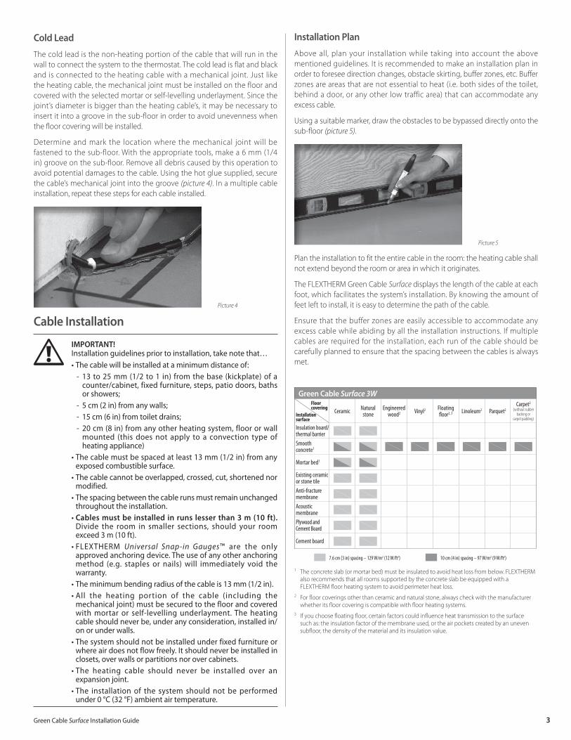
Green Cable Surface 3W
Installationsurface
Ceramic Natural stone
Engineered wood2 Vinyl2 Floating
floor2, 3 Linoleum2 Parquet2Carpet2
(without rubber backing or
carpet padding)
Insulation board/thermal barrierSmooth concrete1
Mortar bed1
Existing ceramic or stone tileAnti-fracture membraneAcoustic membranePlywood and Cement Board
Cement board
7.6 cm (3 in) spacing – 129 W/m2 (12 W/ft2) 10 cm (4 in) spacing – 97 W/m2 (9 W/ft2)
1 The concrete slab (or mortar bed) must be insulated to avoid heat loss from below. FLEXTHERM also recommends that all rooms supported by the concrete slab be equipped with a FLEXTHERM floor heating system to avoid perimeter heat loss.
2 For floor coverings other than ceramic and natural stone, always check with the manufacturer whether its floor covering is compatible with floor heating systems.
3 If you choose floating floor, certain factors could influence heat transmission to the surface such as: the insulation factor of the membrane used, or the air pockets created by an uneven subfloor, the density of the material and its insulation value.
Floor covering

4 Green Cable Surface Installation Guide
Room longer or wider than 3 m (10 feet)
1. Do a small detour to break up the cable run.
2. Ensure the chosen spacing is respected all around.
3. Change direction if you need more flexibility to get closer to the wall.
Installation with two cables
1. End the installation of the first cable by the wall, so that the second cable nestles in easily.
Proper spacing to walls and fixed objects
1. Change directions so the cable can be installed to the closest spacing allowed from walls and fixed furniture.
Bathroom example
1. Buffer zones.
Gauge and Cable Installation
Use a hot glue gun to secure the gauges to the sub-floor. Hot glue sticks are included in your kit. For maximum adherence, apply hot glue uniformly under the gauges. Never touch the cable with the glue gun tip. It is suggested that the glue gun be rested on a piece of cardboard during installation.
Install the gauges as the work progresses by joining them together (picture 6).
Picture 6
Slide the cable through the circular shapes by applying a slight pressure. Apply moderate tension on the cable allowing it to remain parallel.
5Green Cable Surface Installation Guide
To get around obstacles such as diagonal walls, fixed furniture, etc., install the gauges in such a way that they follow the shape of the obstacle. In this way the gauges always remain parallel to each other and perpendicular to the cable run (picture 7). When there is insufficient space for the cable to return change the direction of the cable.
Picture 7
Should the installation include a podium bath, glue the cable to the riser making sure the cable is not bent at a 90 degree angle and leave a wide curve to allow for its expansion due to heat (picture 8).
Picture 8
The cables should be stabilized at regular one-meter intervals (every 3-4 feet) with cable guides.. Snap together the required number of gauges and insert them upside down under the cable runs so the cables don’t snag in them. Once inserted, turn them over and slide the cables between the circular forms. Move the gauges slightly to one side making the cable more stable and secure them to the floor.
A typical installation of the FLEXTHERM heating floor system in a bathroom is shown (picture 9).
Picture 9
Wet Environment Installation
The Green Cable Surface can be installed in a wet environment such as a European style shower floor or sauna with a ceramic or natural stone floor.* However, additional precautions must be observed. • The thermostat must be located at least 1 m (3 ft 3 in) away from the wet
zone so that it cannot be reached by a person in that area. • The shower must have its own cable. • Make sure not to damage the waterproof membrane.• The installation must be per formed in accordance with all other
instructions listed on page 4, such as minimum distance from the drain, prohibition of installing the cable in walls, etc.
* Applications must be validated with local and/or national electrical codes.
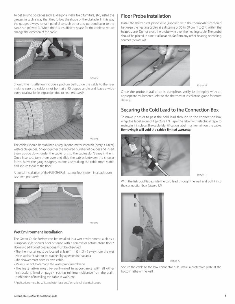
Floor Probe InstallationInstall the thermostat probe wire (supplied with the thermostat) centered between the heating cables at a distance of 30 to 60 cm (1 to 2 ft) within the heated zone. Do not cross the probe wire over the heating cable. The probe should be placed in a neutral location, far from any other heating or cooling sources (picture 10).
Picture 10
Once the probe installation is complete, verify its integrity with an appropriate multimeter (refer to the thermostat installation guide for more details).
Securing the Cold Lead to the Connection BoxTo make it easier to pass the cold lead through to the connection box wrap the label around it (picture 11). Tape the label with electrical tape to maintain it in place. The cable identification label must remain on the cable. Removing it will void the cable’s limited warranty.
Picture 11
With the fish cord/tape, slide the cold lead through the wall and pull it into the connection box (picture 12).
Picture 12
Secure the cable to the box connector hub. Install a protective plate at the bottom lathe of the wall.
6 Green Cable Surface Installation Guide
Cable VerificationOnce the cable installation is completed, once again verify the cable’s integrity as explained in the section “Cable Verification”. Record the results on the limited warranty card. Should the cable have been damaged during installation, do not install the flooring. Call your local FLEXTHERM customer service at HK number + 852 2411 7280.
System ProtectionBetween the installation of the cable and the laying of the flooring, protect the cable with cardboard or similar soft material and restrict access to the area. A hard material (such as a plywood sheet) could damage the cable.
It is recommended to take photographs of the cable installation before installing the flooring. These pictures will prove that your installation meets all the standards and written instructions and will be a useful reminder should you have to renovate.
Floor Covering InstallationGeneral Overview of the Various Techniques
Once the cable has been installed and tested, proceed to the application of the mortar or self-levelling underlayment and the installation of the floor covering.
FLEXTHERM’s floor heating system is compatible with high-grade polymer-modified mortars and can also be embedded in high-grade polymer-modified self-levelling underlayments. Please refer to the manufacturer’s recommendations in regards to the use of their product with floor heating systems.
FLEXTHERM proposes two common installation techniques: the mortar glazing technique and the self-levelling underlayment glazing technique. Please note that the following instructions do not represent a complete flooring installation guide. They only pinpoint the specificities to be observed while installing over a floor heating system. Always follow the flooring manufacturer’s directions in regards to the use of their products.
Floor Covering Laying Techniques
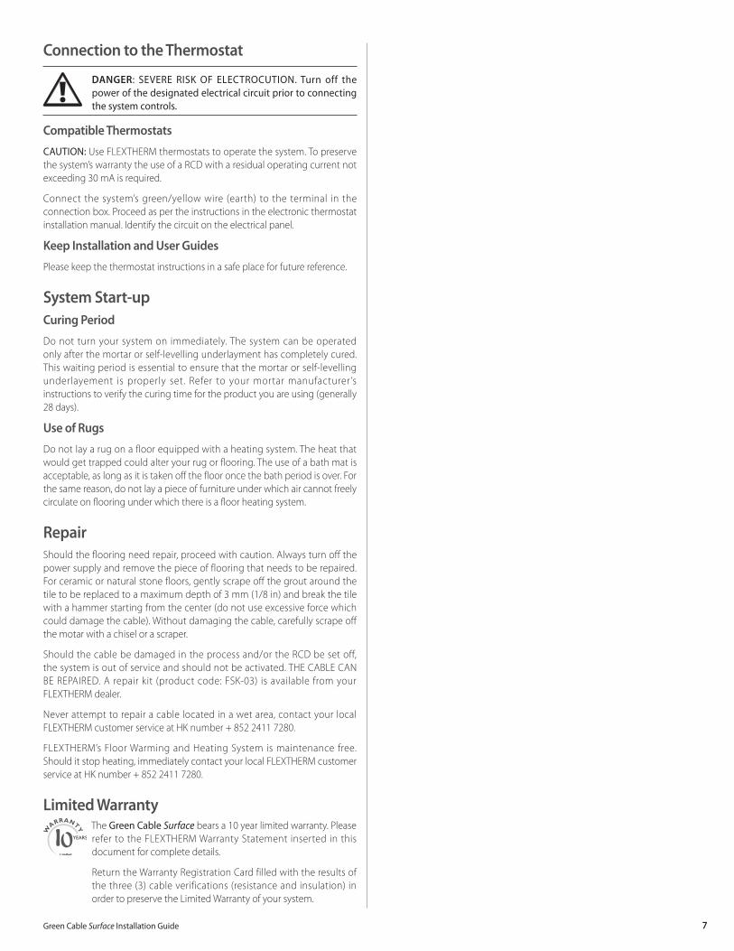
1. Polymer-modified Mortar Glazing Technique (picture 13) – Ceramic or natural stone flooring
Picture 13
This technique involves glazing the cables with the same type of mortar that will be used for the ceramic or stone tile installation. A thin layer of polymer-modified mortar is spread over the cable (in the same direction as the wire) with a flat trowel. Pull the trowel at a 45° angle using a little pressure. Spread the mortar in a way that the space between the cables is completely filled. It is not necessary to fully cover the gauges.
Once the glaze is set, proceed with laying the tile as per the manufacturer’s recommendations. Please note that appropriate care should be taken during ceramic or stone tile installation to not damage the cable.
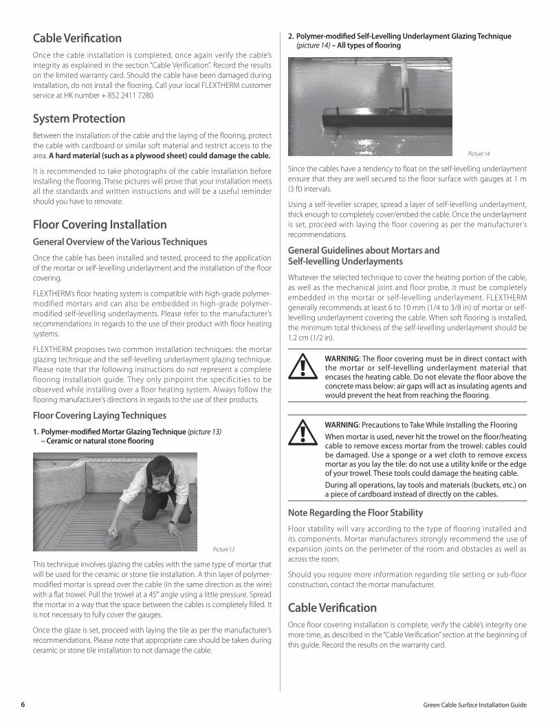
2. Polymer-modified Self-Levelling Underlayment Glazing Technique (picture 14) – All types of flooring
Picture 14
Since the cables have a tendency to float on the self-levelling underlayment ensure that they are well secured to the floor surface with gauges at 1 m (3 ft) intervals.
Using a self-leveller scraper, spread a layer of self-levelling underlayment, thick enough to completely cover/embed the cable. Once the underlayment is set, proceed with laying the floor covering as per the manufacturer’s recommendations.
General Guidelines about Mortars and Self-levelling Underlayments
Whatever the selected technique to cover the heating portion of the cable, as well as the mechanical joint and floor probe, it must be completely embedded in the mortar or self-levelling underlayment. FLEXTHERM generally recommends at least 6 to 10 mm (1/4 to 3/8 in) of mortar or self-levelling underlayment covering the cable. When soft flooring is installed, the minimum total thickness of the self-levelling underlayment should be 1.2 cm (1/2 in).
WARNING: The floor covering must be in direct contact with the mortar or self-levelling underlayment material that encases the heating cable. Do not elevate the floor above the concrete mass below: air gaps will act as insulating agents and would prevent the heat from reaching the flooring.
WARNING: Precautions to Take While Installing the FlooringWhen mortar is used, never hit the trowel on the floor/heating cable to remove excess mortar from the trowel: cables could be damaged. Use a sponge or a wet cloth to remove excess mortar as you lay the tile: do not use a utility knife or the edge of your trowel. These tools could damage the heating cable.During all operations, lay tools and materials (buckets, etc.) on a piece of cardboard instead of directly on the cables.
Note Regarding the Floor Stability
Floor stability will vary according to the type of flooring installed and its components. Mortar manufacturers strongly recommend the use of expansion joints on the perimeter of the room and obstacles as well as across the room.
Should you require more information regarding tile setting or sub-floor construction, contact the mortar manufacturer.
Cable VerificationOnce floor covering installation is complete, verify the cable’s integrity one more time, as described in the “Cable Verification” section at the beginning of this guide. Record the results on the warranty card.
7Green Cable Surface Installation Guide
Connection to the Thermostat
DANGER: SEVERE RISK OF ELECTROCUTION. Turn off the power of the designated electrical circuit prior to connecting the system controls.
Compatible Thermostats
CAUTION: Use FLEXTHERM thermostats to operate the system. To preserve the system’s warranty the use of a RCD with a residual operating current not exceeding 30 mA is required.
Connect the system’s green/yellow wire (earth) to the terminal in the connection box. Proceed as per the instructions in the electronic thermostat installation manual. Identify the circuit on the electrical panel.
Keep Installation and User Guides
Please keep the thermostat instructions in a safe place for future reference.
System Start-upCuring Period
Do not turn your system on immediately. The system can be operated only after the mortar or self-levelling underlayment has completely cured. This waiting period is essential to ensure that the mortar or self-levelling underlayement is properly set. Refer to your mortar manufacturer ’s instructions to verify the curing time for the product you are using (generally 28 days).
Use of Rugs
Do not lay a rug on a floor equipped with a heating system. The heat that would get trapped could alter your rug or flooring. The use of a bath mat is acceptable, as long as it is taken off the floor once the bath period is over. For the same reason, do not lay a piece of furniture under which air cannot freely circulate on flooring under which there is a floor heating system.
RepairShould the flooring need repair, proceed with caution. Always turn off the power supply and remove the piece of flooring that needs to be repaired. For ceramic or natural stone floors, gently scrape off the grout around the tile to be replaced to a maximum depth of 3 mm (1/8 in) and break the tile with a hammer starting from the center (do not use excessive force which could damage the cable). Without damaging the cable, carefully scrape off the motar with a chisel or a scraper.
Should the cable be damaged in the process and/or the RCD be set off, the system is out of service and should not be activated. THE CABLE CAN BE REPAIRED. A repair kit (product code: FSK-03) is available from your FLEXTHERM dealer.
Never attempt to repair a cable located in a wet area, contact your local FLEXTHERM customer service at HK number + 852 2411 7280.
FLEXTHERM’s Floor Warming and Heating System is maintenance free. Should it stop heating, immediately contact your local FLEXTHERM customer service at HK number + 852 2411 7280.
Limited WarrantyThe Green Cable Surface bears a 10 year limited warranty. Please refer to the FLEXTHERM Warranty Statement inserted in this document for complete details.
Return the Warranty Registration Card filled with the results of the three (3) cable verifications (resistance and insulation) in order to preserve the Limited Warranty of your system.

8 Green Cable Surface Installation Guide
LIMITED WARRANTY FLExTHERM Heating Cable – Green CableTM Surface
FLEXTHERM Inc. (hereinafter “FLEXTHERM”) warrants to the original purchaser that the low temperature electric radiant floor heating system cable (hereinafter the “Product”) as designed and manufactured by FLEXTHERM, and once installed in conformity with the instructions of FLEXTHERM, shall be free of defects, in either materials or workmanship as described in this document.
COVERAGE PERIOD:
This Limited Warranty becomes effective on the date of purchase of the Product by the first owner and shall remain effective for a period of ten (10) years [one hundred and twenty (120) consecutive months] from the date of original purchase of the cables. This Limited Warranty is valid for Products bought and installed in Hong Kong, Macao and Mainland China only.
CONDITIONS:
This Limited Warranty is only applicable to new and unused Products purchased from FLEXTHERM, or its authorised re-sellers, provided the Installation Requirements contained in the Product Installation Guide are met. Claims made for coverage under this Limited Warranty must be addressed in writing to: REGENT INTERNATIONAL (H.K.) LTD. FLAT D, 2/F., WAYLEE INDUSTRIAL CENTRE, 38 TSUEN KING CIRCUIT, TSUEN WAN, N.T., HONG KONG, within seventy-two (72) hours from an event giving rise to a claim, or the appearance of a defect.
Persons making claims for coverage must present FLEXTHERM with proof of purchase as well as proof of installation in accordance with the Installation Requirements (pictures recommended) and any documents FLEXTHERM may require.
Any parts replaced under the terms of this Limited Warranty become the property of FLEXTHERM.
WHAT FLExTHERM WILL/WILL NOT DO:
FLEXTHERM’s obligations under this Limited Warranty are limited to, at its sole discretion, repairing or reimbursing the cables originally supplied in the Product that FLEXTHERM has determined to be defective in materials or workmanship.
FLEXTHERM shall repair or reimburse, at its sole and entire discretion, the defective cable goods free of charge. Repair or replacement will only be made for defective parts; and no allowance or reimbursement shall be made for wages, labor and freight costs. Should FLEXTHERM choose to reimburse the cost of the cable, it will do so at the lesser of the value of the purchase price or the suggested retail price for the same item. With respect to the parts not manufactured by ourselves, we shall only warrant these to the same extent as our suppliers undertake a warranty obligation towards ourselves.
Because of our ongoing commitment to product quality and innovation, FLEXTHERM reserves the right, at any time and without incurring any
obligations, to revise, change, modify or discontinue any specifications, features, designs or components.
INSTALLATION REQUIREMENTS:In addition to the requirements included in the current FLEXTHERM Installation Guide, which is incorporated herein by this reference, the Product must be installed in accordance with accepted standards, with FLEXTHERM thermostats (or a suitable equivalent, as determined by FLEXTHERM) and with adhesives that are compatible with an electrical in floor heating system.
WARNING: Failure to install the Product with controls and protection systems (including Residual Current Device) in conformity with your local electrical Codes, as well as the Installation Guide, may cause fires.
WARNING: Failure to install the Product with the appropriate cable/wire installation gauges may damage the cables/wiring and lead to Product failures, which are not covered under the Limited Warranty.
WARNING: Failure to install the Product with a good quality polymer-modified mortar or polymer-modified self-levelling underlayment may lead to failures and defects, which are not covered under this Limited Warranty.
Floor Warming and Heating Systems
✁
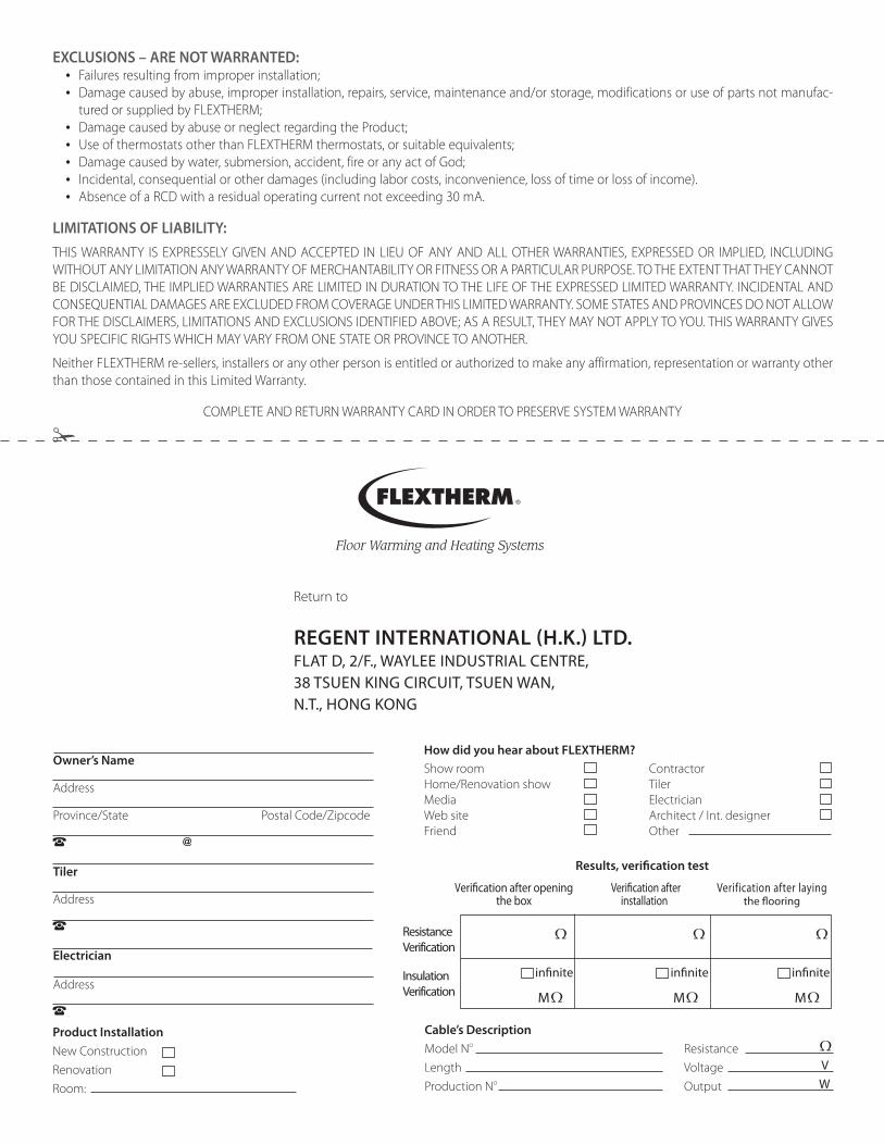
Return to
REGENT INTERNATIONAL (H.K.) LTD. FLAT D, 2/F., WAyLEE INDUSTRIAL CENTRE, 38 TSUEN KING CIRCUIT, TSUEN WAN, N.T., HONG KONG
Floor Warming and Heating Systems
COMPLETE AND RETURN WARRANTY CARD IN ORDER TO PRESERVE SYSTEM WARRANTY
ExCLUSIONS – ARE NOT WARRANTED:• Failures resulting from improper installation;• Damage caused by abuse, improper installation, repairs, service, maintenance and/or storage, modifications or use of parts not manufac-
tured or supplied by FLEXTHERM;• Damage caused by abuse or neglect regarding the Product;• Use of thermostats other than FLEXTHERM thermostats, or suitable equivalents;• Damage caused by water, submersion, accident, fire or any act of God;• Incidental, consequential or other damages (including labor costs, inconvenience, loss of time or loss of income).• Absence of a RCD with a residual operating current not exceeding 30 mA.
LIMITATIONS OF LIABILITY:THIS WARRANTY IS EXPRESSELY GIVEN AND ACCEPTED IN LIEU OF ANY AND ALL OTHER WARRANTIES, EXPRESSED OR IMPLIED, INCLUDING WITHOUT ANY LIMITATION ANY WARRANTY OF MERCHANTABILITY OR FITNESS OR A PARTICULAR PURPOSE. TO THE EXTENT THAT THEY CANNOT BE DISCLAIMED, THE IMPLIED WARRANTIES ARE LIMITED IN DURATION TO THE LIFE OF THE EXPRESSED LIMITED WARRANTY. INCIDENTAL AND CONSEQUENTIAL DAMAGES ARE EXCLUDED FROM COVERAGE UNDER THIS LIMITED WARRANTY. SOME STATES AND PROVINCES DO NOT ALLOW FOR THE DISCLAIMERS, LIMITATIONS AND EXCLUSIONS IDENTIFIED ABOVE; AS A RESULT, THEY MAY NOT APPLY TO YOU. THIS WARRANTY GIVES YOU SPECIFIC RIGHTS WHICH MAY VARY FROM ONE STATE OR PROVINCE TO ANOTHER.
Neither FLEXTHERM re-sellers, installers or any other person is entitled or authorized to make any affirmation, representation or warranty other than those contained in this Limited Warranty.
How did you hear about FLExTHERM?Show roomHome/Renovation showMediaWeb siteFriend
ContractorTilerElectricianArchitect / Int. designerOther
Cable’s DescriptionModel No
Length Production No
Resistance Voltage V
Output W
Product InstallationNew ConstructionRenovationRoom:
Verification after opening the box
Verification after installation
Verification after laying the flooring
ResistanceVerification InsulationVerification
Results, verification test
infinite
M
Owner’s Name
Address
Province/State Postal Code/Zipcode
Tiler
Address
Electrician
Address
infinite
M
infinite
M


Floor Warming and Heating Systems
FLEXTHERM Inc.2400 de la Province, Longueuil, Québec J4G 1G1 Canada
www.flextherm.com 5701
0003
102
012
• P
rinte
d in
Can
ada
Regent International (H.K.) Ltd.Flat D, 2/F., Waylee Industrial Centre,
38 Tsuen King Circuit, Tsuen Wan, N.T., Hong [email protected]