floor mounted - elite boilereliteboiler.com/pdfs/lp-293.pdf · floor mounted wall mounted ... the...
TRANSCRIPT

n WARNINGThis manual must only be used by a qualified heating installer/service technician. Read all instructionsin this manual before installing. Perform steps in the order given. Failure to comply could result insevere personal injury, death or substantial property damage.
InstallationManual
• Installation• Startup• Maintenance• Parts
InstallationManual
• Installation• Startup• Maintenance• Parts
NOTICE
Heat Transfer Products, Inc., reserves the right to make product changes or updates withoutnotice and will not be held liable for typographical errors in literature.
Floormounted
Wallmounted
ModelsEL-80 N/LP EL-220 N/LPEL-110 N/LP EL-299 N/LPEL-150 N/LP EL-399 N/LP

1
Boiler Manual
WARNING
WHAT TO DO IF YOU SMELL GAS• Do not try to light any appliance.• Do not touch any electrical switch:
do not use any phone in yourbuilding.
• Immediately call your gas supplierfrom a neighbor's phone. Follow the
gas supplier's instructions.• If you cannot reach your gas
supplier, call the fire department.Installation and service must beperformed by a qualified installer,service agency or the gas supplier.
If the information in this manual is not followedexactly, a fire or explosion may result causingproperty damage, personal injury or loss of life.
Do not store or use gasoline or other flammablevapors and liquids in the vicinity of this or anyother appliance.

Boiler Manual
2
CONTENTSPart 1 – Product and Safety Information . . . . . . . . . . . . . . . . . . . . . . . . . . . . . . . . . . . . . 4-6Part 2 – Before You Start. . . . . . . . . . . . . . . . . . . . . . . . . . . . . . . . . . . . . . . . . . . . . . . . . . . 6-7
A. What’s In The BoxB. How The Boiler OperatesC. Optional Equipment
Part 3 – Prepare Boiler Location . . . . . . . . . . . . . . . . . . . . . . . . . . . . . . . . . . . . . . . . . . . . 8-13A. Boiler Location / DimensionsB. Installations Must Comply With:C. Before Locating the BoilerD. Clearances for Service AccessE. Residential Garage InstallationF. Exhaust Vent and Intake Air VentG. Prevent Combustion Air ContaminationH. When Removing a Boiler from an Existing Common Vent System
Part 4 – Prepare Boiler . . . . . . . . . . . . . . . . . . . . . . . . . . . . . . . . . . . . . . . . . . . . . . . . . . . . . 14Part 5 – Boiler Piping . . . . . . . . . . . . . . . . . . . . . . . . . . . . . . . . . . . . . . . . . . . . . . . . . . . . 14-24
A. Relief ValveB. General Piping InformationC. Backflow PreventerD. System Water Piping MethodsE. CirculatorsF. Hydronic Piping with Circulators, Zone Valves and Multiple BoilersG. Boiler Piping DetailsH. Circulator SizingI. Fill and Purge Heating SystemJ. Zoning with Zone ValvesK. Zoning with CirculatorsL . Multiple Boilers
Part 6 – Venting, Combustion Air & Condensate Removal . . . . . . . . . . . . . . . . . . . . . 25-36A. Installing Exhaust Vent and Intake Air VentB. GeneralC. Approved Materials for Exhaust Vent and Intake Air VentD. Exhaust Vent and Intake Air Vent Pipe LocationE. Exhaust Vent and Intake Air Vent SizingF. Longer Vent RunsG. Exhaust Vent and Intake Air Pipe InstallationH. Heater Removal from a Common Vent SystemI. Diagrams for Sidewall VentingJ. Diagram for Vertical VentingK. Diagram for Horizontal VentingJ. Diagram for Unbalanced Flue Venting
Part 7 – Gas Piping. . . . . . . . . . . . . . . . . . . . . . . . . . . . . . . . . . . . . . . . . . . . . . . . . . . . . . 37-39A. Gas ConnectionB. Gas PipingC. Check Inlet Gas PressureD. Elite Heating Boiler® Gas Valve

Boiler Manual
3
CONTENTS (CONT’D)
Part 8 – Field Wiring. . . . . . . . . . . . . . . . . . . . . . . . . . . . . . . . . . . . . . . . . . . . . . . . . . . . . 40-48A. Installation Must Comply WithB. Field WiringC. Line Voltage Wiring for Standard BoilerD. Low Voltage Connections for Standard BoilerE. ThermostatF. Outdoor SensorG. Indirect SensorH. Optional 0-10 Volt Building Control SignalI. Optional UL353 Low Water Cut-off Interface KitJ. Wiring of Cascade System Communication Bus
Part 9 – Start Up Preparation . . . . . . . . . . . . . . . . . . . . . . . . . . . . . . . . . . . . . . . . . . . . . 49-52A. Check/Control Water ChemistryB. Freeze Protection (when used)C. Fill and Test Water SystemD. Purge Air from Water SystemE. Check for Gas LeaksF. Check Thermostat Circuit(s)G. Condensate RemovalH. Final Checks Before Starting BoilerI. Cascade System
Part 10 – Start-Up Procedure . . . . . . . . . . . . . . . . . . . . . . . . . . . . . . . . . . . . . . . . . . . . . 52-59A. Control OverviewB. Navigation of the DisplayC. Operating InstructionsD. Programming Boiler SettingsE. Programming the System SettingF. System Setting Program Navigation
Part 11 – Start-Up Procedures for the Installer. . . . . . . . . . . . . . . . . . . . . . . . . . . . . . . 60-64A. Elite Heating Boiler Control Status MenuB. Elite Heating Boiler Test ModeC. Cascade MenuD. Test Mode Access
Part 12 – Troubleshooting. . . . . . . . . . . . . . . . . . . . . . . . . . . . . . . . . . . . . . . . . . . . . . . . 65-73A. Elite Heating Boilers® Error CodeB. Boiler ErrorC. Boiler FaultD. User Interface Display
Part 13 – Maintenance. . . . . . . . . . . . . . . . . . . . . . . . . . . . . . . . . . . . . . . . . . . . . . . . . . . 74-81A. Maintenance ProceduresB. Combustion Chamber Coil Cleaning Instructions for Elite Heating Boiler®
— Boiler Start Up Report— Boiler Inspection and Maintenance Schedule— Additional Local Requirements

Boiler Manual
4
PART 1: PRODUCT AND SAFETY INFORMATION
SPECIAL ATTENTION BOXESThe following defined terms are used throughout this manual to bring attention to the presence ofhazards of various risk levels or to important information concerning the product.
n DANGERDANGER indicates an imminently hazardoussituation which, if not avoided, will result indeath or serious injury.
n WARNINGWARNING indicates a potentially hazardoussituation which, if not avoided, could result indeath or serious injury.
n CAUTIONCAUTION Indicates a potentially hazardoussituation which, if not avoided, may result inminor or moderate injury.
CAUTIONCAUTION used without the safety alert symbolindicates a potentially hazardous situation which,if not avoided, may result in property damage.
DEFINITIONS
This appliance must be installed by qualified and licensed personnel in accordance withlocal codes, or in the absence of local codes, by the national fuel gas code, ANSI Z223.1-2002. This appliance is for indoor installations only. Clearance to combustible materials: 0”top, bottom, sides and back. Front must have room for service, 24” recommended. (Acombustible door or removable panel is acceptable front clearance.) This appliance hasbeen approved for closet installation. Do not install this appliance directly on carpeting.

Boiler Manual
5
PART 1: PRODUCT AND SAFETY INFORMATION (CONT’D)
BEFORE INSTALLING
WHEN SERVICING BOILER
• To avoid electric shock, disconnect electricalsupply before performing maintenance.
• To avoid severe burns, allow boiler to coolbefore performing maintenance.
BOILER OPERATION
• Do not block flow of combustion orventilation air to boiler.
• Should overheating occur or gas supply fail toshut off, do not turn off or disconnect electricalsupply to circulator. Instead, shut off the gassupply at a location external to the appliance.
• Do not use this boiler if any part has beenunder water. Immediately call a qualifiedservice technician to inspect the boiler and toreplace any part of the control system andany gas control that has been under water.
BOILER WATER
• If you have an old system with cast iron radiators,thoroughly flush the system (without boilerconnected) to remove sediment. The high-efficiencyheat exchanger can be damaged by build-up orcorrosion due to sediment. HTP recommends asuction strainer in this type of system.
• Do not use petroleum-based cleaning or sealingcompounds in boiler system. Gaskets and sealsin the system may be damaged. This can resultin substantial property damage.
• Do not use “homemade cures” or “boiler patentmedicines.” Substantial property damage,damage to boiler, and/or serious personal injurymay result.
n WARNINGInstaller — Read all instructions in this manual,and Elite Heating Boilers® Venting section,before installing. Perform steps in the ordergiven.
User — This manual is for use only by aqualified heating installer/service technician.Refer to User’s Information Manual for yourreference.
User — Have this boiler serviced/inspected bya qualified service technician annually.
Failure to comply with the above could result insevere personal injury, death or substantialproperty damage.
n WARNINGFailure to adhere to the guidelines on this pagecan result in severe personal injury, death orsubstantial property damage.
n WARNINGWHAT TO DO IF YOU SMELL GAS• Do not try to light any appliance.• Do not touch any electric switch; do not use
any phone in your building.• Immediately call your gas supplier from a
neighbor's phone. Follow the gas suppliers'instructions.
• If you cannot reach your gas supplier, call thefire department.
CAUTIONDue to the low water content of the boiler,improper sizing of the boiler with regard to theheating system load will result in excessiveboiler cycling and accelerated componentfailure. Heat Transfer Products DOES NOTwarrant failures caused by mis-sized boilerapplications. DO NOT oversize the boiler to thesystem. Modular boiler installations greatlyreduce the likelihood of boiler oversizing.

Boiler Manual
6
PART 2: BEFORE YOU STARTA. WHAT’S IN THE BOX
Also included with the Elite Heating Boilers® are:• Pressure and Temperature Gauge• Indirect Sensor • Installation Manual• Outdoor Sensor • Warranty• Pressure Relief Valve • CSD-1 Form• Intake PVC Tee with • H-3 Data Sheet
Screens• Exhaust PVC Coupling with Screens• Outlet Combination
Fitting— 1" – 7450P-134 for Models –
EL-80/110/150/220— 1.25" – 7450P-135 for Models – EL-299— 1.50" – 7450P-136 for Models – EL-399
B. HOW BOILER OPERATES
Elite Heating Boiler® Condensing Technology isan intelligent system that delivers highly effi-cient hydronic heating, while maximizing effi-ciency. Outlined below are the features of thesystem and how they operate:1. Stainless Steel Heat Exchanger – The highly
efficient Elite Heating Boiler® Stainless SteelHeat exchanger is designed to use the coldreturn water from the system and extract thelast bit of heat before it is exhausted.
2. Modulating Combustion System – Thecombustion system will modulate the output of
the burner during operation to match thesystem demand and achieve the control setpoint while in operation. The set point canchange by internal or external signals whichenhance the overall performance of the system.
3. Control – The integrated control systemmonitors the system and regulates the fanspeed to control the boilers output. Thisallows the boiler to deliver only the amountof heat energy required and nothing more.This control can be set up to monitor outdoortemperature through an outdoor sensor toregulate the set point of the boiler. Thesystem can be further enhanced by installingwith an indirect water heater to providedomestic hot water.The control can regulate the output ofmultiple boilers through its cascade systemfunction. The cascade system is capable ofconnecting up to eight boilers together insuch a way that they function as one boilersystem. This allows for greater turn downratios and provides systematic control of themultiple boilers in an installation to minimizedowntime and maximize efficiency.The cascade system works by establishing oneboiler as the master and the other connectedboilers as followers. The master boiler requiresa cascade system sensor and a cascade pumpin addition to its own boiler pump. Each of thefollower boilers have an individual pumpconnected to each follower boiler.
PART 1: PRODUCT AND SAFETY INFORMATION (CONT’D)
CAUTIONConsider piping and installation whendetermining boiler location.
n CAUTIONNEVER use automotive or standard glycolantifreeze, ethylene glycol made for hydronicsystems. Use only inhibited propylene glycolsolutions, which are specifically formulated forhydronic systems. Ethylene glycol is toxic and canattack gaskets and seals used in hydronic systems.
• Continual fresh make-up water will reduce boilerlife. Mineral buildup in the heat exchangerreduces heat transfer, overheats the stainlesssteel heat exchanger, and causes failure.Addition of oxygen in by make-up water cancause internal corrosion in system components.Leaks in the boiler or piping must be repaired atonce.
FREEZE PROTECTION FLUIDS

7
Boiler Manual
PART 2: BEFORE YOU START (CONT’D)
4. Text Display and Operational Led lightIndicators – The display allows the user tochange the system parameters and monitorthe system outputs.
5. Gas Valve – The gas valve senses suctionfrom the blower allowing gas to flow only ifthe gas valve is powered and combustion airis flowing.
6. All Metal Integrated Venturi – Controls the airand gas flow into the burner.
7. Burner – Constructed of high grade stainlesssteel, the burner uses premixed air and gasfuel and provides a wide range of firing rates.
8. Spark Ignition – The burner is ignited byapplying a high voltage through the systemspark electrode. This causes the spark fromthe electrode to ignite the mixed gas off ofthe burner.
9. Supply Water Temperature Sensor – Thissensor monitors the boiler outlet watertemperature (System Supply). The controladjusts the boiler firing rate so the supplytemperature will match the boiler set point.
10. Return Water Temperature Sensor – Thissensor monitors the boiler return watertemperature (System Return).
11. Flue Sensor – Monitors flue temperature andadjusts firing rate.
12. Temperature and Pressure Gauge – Allowsthe user to monitor the system temperatureand pressure.
13. Electrical field connections with terminalstrips – The electrical cover allows easyaccess to the line voltage and low voltageterminals strips which are clearly marked tofacilitate wiring of the boiler.
14. Condensation Collection System – This boileris a high efficiency appliance, therefore theboiler will produce condensate. The collectionsystem has a float switch which monitors thecondensation level and prevents condensationfrom backing up into the combustion system.Inside the collection system there is a built intrap which seals the combustion system fromthe connected drain. This condensate shouldbe neutralized to avoid damage to thedrainage system or piping.
15. Outdoor Sensor – The outdoor sensor willmonitor the outdoor temperature and adjust
the unit’s set point to provide greater efficiency.16. 0-10 Volt Input – Allows Installer to connect
to a BMS (Building Management System) tocontrol the boiler.
17. Condensate Flue Check System – The Checksystem prevents exhaust from the heatexchanger from backing up into cabinet.
18. Pump Service Mode – Allows manualoperation of pumps to commission systemand check pump operation.
19. The Vision II system allows the user to supplymixed temperatures in up to eight zoneswhen connected to the Elite Boiler. TheVision II system controls the temperature toeach zone by employing three way mixingvalves. The Vision II also controls the outputtemperature of the Elite Boiler to assureaccurate temperature delivery to all theconnected zones.
C. OPTIONAL EQUIPMENT
Below is the list of optional equipment availablefor Elite Heating Boiler®.• Wall Mount Bracket (Part # 7450P-211)• System Sensor (Part # 7250P-324)• Indirect Sensor (Part # 7250P-325)• 3" Stainless Steel Outside Termination Vent
Kit (V1000)• 4” Stainless Steel Outside Termination Vent
Kit (V2000)• 6” Stainless Steel Outside Termination Vent
Kit (V3000)• 3 " P V C C o n c e n t r i c Ve n t K i t ( Pa r t
#KGAVT0601CVT)• U.L. 353 Compliant Low Water Cut-Off Interface
Kit with Manual Reset (Part # 7450P-225)• Alarm System (Part # 7350P-602) (to monitor
any failure)• PC Connection Kit (Part # 7250P-320)• Elite Heating Boiler® Condensate Neutralizer
(Part # 7450P-212 for EL-80/110/150/220/299,Part # 7350P-611 for EL-399)
• Flow Switch Kit (Part # 7450P-213 forEL-80/110/150/220, EL-220, Part # 7450P-214for EL-299, Part # 7450P-215 for EL-399)
• Vision II (Part # 7250P-322)These additional options may be purchasedthrough your HTP Distributor.

8
n CAUTIONWhen preparing the boiler location, make sure the area where you are placing the boiler is level. In orderfor the condensate to properly flow out of the collection system, the boiler must be level to assure properflow direction. The Elite Heating Boiler® comes equipped with leveling feet. Should you find the floorbeneath the boiler is uneven, adjust the leveling feet with a wrench.
INCORRECT CORRECT
INCORRECT CORRECT
PART 3: PREPARE BOILER LOCATION
Boiler Manual
A. BOILER LOCATION / DIMENSIONS
Before considering the Boiler location, there aremany factors that have to be addressed. Thesefactors are covered in detail in this installation
manual. Please read the entire manual as itcould save time and money. Piping, Venting, andCondensation Removal are just a few issues thatneed to be addressed prior to the installation ofthe boiler.

Boiler Manual
9
LP-285-A Rev. 1/14/10Figure 3-1
DIMENSIONS
*"N" DENOTES NATURAL GAS, "LP" DENOTES PROPANEALL DIMENSIONS ARE APPROXIMATE AND ARE SUBJECT TO CHANGE

10
Boiler Manual
LP-285-A Rev. 1/14/10Figure 3-2
DIMENSIONS
*"N" DENOTES NATURAL GAS, "LP" DENOTES PROPANEALL DIMENSIONS ARE APPROXIMATE AND ARE SUBJECT TO CHANGE

11
Boiler Manual
• Incorrectly-sized expansion tank.• Lack of freeze protection in boiler water
causing system and boiler to freeze and leak.• Excessive glycol which will affect the
boiler system operation.
5. Clean and flush system when re-installing aboiler.
D. CLEARANCES FOR SERVICE ACCESS
1. See Figure 3-3 for recommended serviceclearances. If you do not provide minimumclearances shown, it might not be possible toservice the boiler without removing it fromthe space.
E. RESIDENTIAL GARAGE INSTALLATION
PrecautionsTake the following special precautions wheninstalling the boiler in a residential garage. If the
0"24"
0"
24"
16 "
n WARNINGThe space must be provided with combus-tion/ventilation air openings correctly sized forall other appliances located in the same space asthe Elite Heating Boiler®. The boiler cover mustbe securely fastened to the boiler to prevent theboiler from drawing air from inside the boilerroom. This is particularly important if the boileris located in the same room as other appliances.Failure to comply with the above warnings couldresult in severe personal injury, death or sub-stantial property damage.
Figure 3-3 LP-293-K Rev. 9/22/09
SERVICE CLEARANCES
PART 3: PREPARE BOILER LOCATION (CONTINUED)
B. INSTALLATIONS MUST COMPLY WITH:
• Local, state, provincial, and national codes,laws, regulations and ordinances.
• National Fuel Gas Code, ANSI Z223.1 – latestedition.
• Standard for Controls and Safety Devices forAutomatically Fired Boilers, ANSI/ASMECSD-1, when required.
• National Electrical Code.
• For Canada only: B149.1 or B149.2Installation Code, CSA C22.1 CanadianElectrical Code Part 1 and any local codes.
C. BEFORE LOCATING THE BOILER
1. Check for nearby connections to:• System water piping• Venting connections• Gas supply piping• Electrical power• Condensate drain
2. Check area around boiler. Remove anycombustible materials, gasoline and otherflammable liquids.
3. The Elite Heating Boiler® Gas Control Systemcomponents must be protected from drippingwater during operation and service.
4. If the Elite Heating Boiler® is to replace anexisting boiler, check for and correct anyexisting system problems such as:• System leaks.
NOTICEThe Elite Heating Boiler® gas manifold andcontrols met safe l ighting and otherperformance criteria when the boiler underwenttests specified in ANSI Z21.13 — latest edition.
n WARNINGFailure to keep boiler area clear and free ofcombustible materials, gasoline and otherflammable liquids and vapors can result insevere personal injury, death or substantialproperty damage.

12
Boiler Manual
boiler is located in a residential garage, per ANSIZ223.1.
• Mount the boiler with a minimum of 18inches above the floor of the garage to thebottom of the boiler to ensure the burner andignition devices will be no less than 18 inchesabove the floor.
• Locate or protect the boiler so it cannot bedamaged by a moving vehicle.
F. EXHAUST VENT AND INTAKE AIR VENT
The Elite Heating Boiler® requires a special ventsystem, designed for pressurized venting. EliteHeating Boilers® are rated ANSI Z21.13 CategoryIV (pressurized vent, likely to form condensate inthe vent).
You must also install air intake piping from out-doors to the boiler flue adaptor. The resultantinstallation is categorized as direct vent (sealedcombustion). Note: To prevent combustionair contamination see Table 3-4 in thissection when considering exhaust ventand intake air vent termination.
Intake and exhaust must terminate near eachother and may be vented vertically through theroof or out a side wall. The intake and exhaustventing methods are detailed in the VentingSection. Do not attempt to install the EliteHeating Boiler® using any other means. Be sureto locate the boiler such that the air intake andexhaust vent piping can be routed through thebuilding and properly terminated. The air intakeand exhaust vent piping lengths, routing and ter-mination method must all comply with the meth-ods and limits given in the venting section.
G. PREVENT COMBUSTION AIRCONTAMINATION
Install intake air piping for the Elite Heating
PART 3: PREPARE BOILER LOCATION (CONTINUED)
Boiler® as described in the Venting section. Donot terminate exhaust in locations that can allowcontamination of intake air.
n WARNINGYou must pipe outside air to the boiler airintake. Ensure that the intake air will notcontain any of the contaminants below.Contaminated air will damage the boiler,resulting in possible substantial propertydamage, severe personal injury, or death. Forexample, do not pipe intake air vent near aswimming pool. Also avoid areas subject toexhaust fumes from laundry facilities. Theseareas will always contain contaminants.
Products to avoid
Spray cans containing fluorocarbons
Permanent wave solutions
Chlorinated waxes/cleaners
Chlorine-based swimming pool chemicals
Calcium chloride used for thawing
Sodium chloride used for water softening
Refrigerant leaks
Paint or varnish removers
Hydrochloric acid/muriatic acid
Cements and glues
Antistatic fabric softeners used in clothes dryers
Chlorine-type bleaches, detergents, and cleaningsolvents found in household laundry rooms
Adhesives used to fasten building products andother similar products
Areas likely to have contaminants
Dry cleaning/laundry areas and establishments
Swimming pools
Metal fabrication plants
Beauty shops
Refrigeration repair shops
Photo processing plants
Auto body shops
Plastic manufacturing plants
Furniture refinishing areas and establishments
New building construction
Remodeling areas
Garages and workshops
Table 3-4: Corrosive contaminants and sources
n WARNINGVents must be properly supported. The EliteHeating Boiler ’s® Intake and ExhaustConnections are not designed to carry heavyweight. Vent support brackets must be within 1foot of the boiler and the balance at 4 footintervals. The Elite Heating Boiler® ventingmust be readily accessible for visual inspectionfor the first three feet from the boiler.
13
Boiler Manual
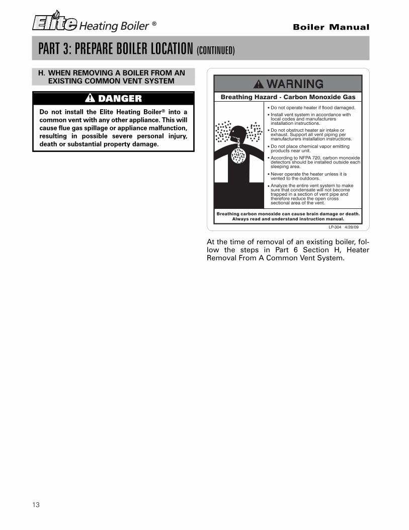
H. WHEN REMOVING A BOILER FROM ANEXISTING COMMON VENT SYSTEM
PART 3: PREPARE BOILER LOCATION (CONTINUED)
At the time of removal of an existing boiler, fol-low the steps in Part 6 Section H, HeaterRemoval From A Common Vent System.
n DANGERDo not install the Elite Heating Boiler® into acommon vent with any other appliance. This willcause flue gas spillage or appliance malfunction,resulting in possible severe personal injury,death or substantial property damage.

14
Boiler Manual
PART 4: PREPARE BOILER
A. RELIEF VALVE
Connect the discharge piping for the relief valve to a safe disposal location, follow the guidelines in theWARNING below.
PART 5: BOILER PIPING
n WARNINGTo avoid water damage or scalding due to relief valve operation:• Discharge line must be connected to relief valve outlet and run to a safe place of disposal. Terminate
the discharge line in a manner that will prevent possibility of severe burns or property damage shouldthe relief valve discharge.
• Discharge line must be as short as possible and be the same size as the valve discharge connectionthroughout its entire length.
• Discharge line must pitch downward from the valve and terminate at least 6” above the floor drainmaking discharge clearly visible.
• The discharge line shall terminate plain, not threaded, with a material serviceable for temperatures of375 °F or greater.
• Do not pipe the discharge to any location where freezing could occur.• No shutoff valve shall be installed between the relief valve and boiler or in the discharge line. Do not
plug or place any obstruction in the discharge line.• Test the operation of the relief valve after filling and pressurizing the system by lifting the lever. Make
sure the valve discharges freely. If the valve fails to operate correctly, replace it with a new relief valve.• Failure to comply with the above guidelines could result in failure of the relief valve to operate,
resulting in possibility of substantial property damage, severe personal injury, or death.
Remove all sides of the Elite Heating Boiler®
shipping crate in order to allow the boiler to belifted into its installation location. The EliteHeating Boiler® is also equipped with levelingfeet that can be used to level the boiler properlyif the surface location is not level. If surfaceflooring is rough, care should be taken whensliding boiler into position, you could catch theleveling feet and damage the boiler if it is slid toits location.
CAUTIONCold weather handling — If boiler has beenstored in a very cold location (below 0°F) beforeinstallation, handle with care until the plasticcomponents come to room temperature.
n WARNINGUncrating Boiler – Any Claims for damage orshortage in shipment must be filed immediatelyagainst the transportation company by theconsignee.
n WARNINGNever use dielectric unions for galvanized steelfittings when connecting to a stainless steelstorage tank or boiler.
15
Boiler Manual
PART 5: BOILER PIPING (CONTINUED)
B. GENERAL PIPING INFORMATION
C. BACKFLOW PREVENTER
Use a backflow preventer specifically designedfor hydronic boiler installations. This valveshould be installed on the cold water fill supplyline per local codes. (See Boiler Piping Details)
D. SYSTEM WATER PIPING METHODS
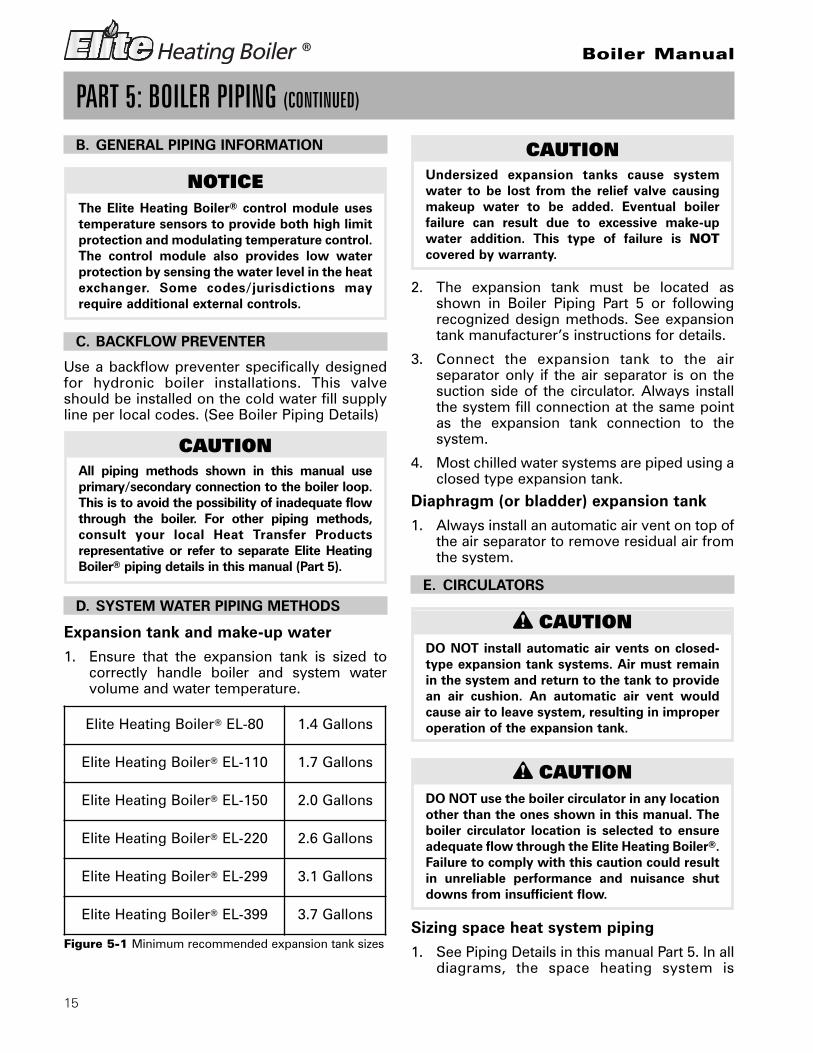
Expansion tank and make-up water1. Ensure that the expansion tank is sized to
correctly handle boiler and system watervolume and water temperature.
2. The expansion tank must be located asshown in Boiler Piping Part 5 or followingrecognized design methods. See expansiontank manufacturer’s instructions for details.
3. Connect the expansion tank to the airseparator only if the air separator is on thesuction side of the circulator. Always installthe system fill connection at the same pointas the expansion tank connection to thesystem.
4. Most chilled water systems are piped using aclosed type expansion tank.
Diaphragm (or bladder) expansion tank1. Always install an automatic air vent on top of
the air separator to remove residual air fromthe system.
E. CIRCULATORS
Sizing space heat system piping1. See Piping Details in this manual Part 5. In all
diagrams, the space heating system is
n CAUTIONDO NOT install automatic air vents on closed-type expansion tank systems. Air must remainin the system and return to the tank to providean air cushion. An automatic air vent wouldcause air to leave system, resulting in improperoperation of the expansion tank.
n CAUTIONDO NOT use the boiler circulator in any locationother than the ones shown in this manual. Theboiler circulator location is selected to ensureadequate flow through the Elite Heating Boiler®.Failure to comply with this caution could resultin unreliable performance and nuisance shutdowns from insufficient flow.
CAUTIONUndersized expansion tanks cause systemwater to be lost from the relief valve causingmakeup water to be added. Eventual boilerfailure can result due to excessive make-upwater addition. This type of failure is NOTcovered by warranty.
Elite Heating Boiler® EL-80 1.4 Gallons
Elite Heating Boiler® EL-110 1.7 Gallons
Elite Heating Boiler® EL-150 2.0 Gallons
Elite Heating Boiler® EL-220 2.6 Gallons
Elite Heating Boiler® EL-299 3.1 Gallons
Elite Heating Boiler® EL-399 3.7 Gallons
NOTICEThe Elite Heating Boiler® control module usestemperature sensors to provide both high limitprotection and modulating temperature control.The control module also provides low waterprotection by sensing the water level in the heatexchanger. Some codes/jurisdictions mayrequire additional external controls.
CAUTIONAll piping methods shown in this manual useprimary/secondary connection to the boiler loop.This is to avoid the possibility of inadequate flowthrough the boiler. For other piping methods,consult your local Heat Transfer Productsrepresentative or refer to separate Elite HeatingBoiler® piping details in this manual (Part 5).
Figure 5-1 Minimum recommended expansion tank sizes

16
Boiler Manual
PART 5: BOILER PIPING (CONTINUED)
isolated from the boiler loop by theprimary/secondary connection.
2. Size the piping and components in the spaceheating system using recognized designmethods.
F. HYDRONIC PIPING WITH CIRCULATORS,ZONE VALVES AND MULTIPLE BOILERS
The Elite Heating Boiler® is designed to function ina closed loop Hydronic System. We have includeda Temperature and Pressure Gauge that allows theuser to monitor the system pressure and outlettemperature from the Elite Heating Boiler®. It is im-portant to note that the Elite Heating Boiler® has aminimal amount of pressure drop and must be cal-culated when sizing the circulators. Each EliteHeating Boiler® installation must have an air elim-ination device that will remove air from the system.
Install the Elite Heating Boiler® so the gas ignitionsystem components are protected from water(dripping, spraying, etc.). Allow clearance for basicservice of boiler circulator, valves and other com-ponents.
Observe the minimum 1” clearance around all un-insulated hot water pipes when openings around
pipes are not protected by non-combustible ma-terials.
On an Elite Heating Boiler® installed above radia-tion level, some states and local codes require alow water cut off device which is optional on theElite Heating Boiler® Rev. 1. Check with local codesfor additional requirements. If the Elite HeatingBoiler® supplies hot water to heating coils in airhandler units, flow control valves or other devicesmust be installed to prevent gravity circulation ofboiler water in the coils during the cooling cycle.
Chilled water medium must be piped in parallelwith the boiler. Freeze protection for new or exist-ing systems must use glycol that is specifically for-mulated for this purpose. It will include inhibitorsthat will prevent the glycol from attacking themetallic system components. Make certain that thesystem fluid is checked for the correct glycol con-centration and inhibitor level. The system shouldbe tested at least once a year and as recommendby the producer of the glycol solution. Allowanceshould be made for the expansion of the glycol so-lution in the system piping. Example: 50% by vol-ume glycol solution expands 4.8% in volume forthe temperature increase from 32 F to 180 F, whilewater expands 3% with the same temperature rise.

17
Boiler Manual
Single Elite Heating Boiler® Space Heating with Indirect Priority
4 PIPE DIAMETER
UNION
DRAIN VALVE
TANK
SWING CHECK
CIRCULATOR
ANTI-SCALDGAUGE
CIRCULATOR
BACKFLOW
DRAINVALVE
FROM SYSTEM
BALL VALVE
TANK
BALL VALVE
GAUGE (TYP)
MIXING VALVE
(TYPICAL)
VALVE
HOT WATER
MAKE-UPWATER
SPACING MAXIMUM
PRESSURE
(OPTIONAL)
CIRCULATOR
ELITE BOILER
TEMP/PRESSURE
PRESSURE
SWING CHECK VALVE
PREVENTER
DRAIN VALVE
(TYPICAL)
INDIRECT
HOT WATER
AIR ELIMINATOR
VALVE
TO SYSTEM
SUPPLY SENSOR
SYSTEM
REDUCING
(PURGE POINT)
EXPANSION
BOILER
OUTLET COMBINATIONFITTING
PRESSURERELIEFVALVE ((TYP)
INLET
HOT WATEROUTLET
COLD WATER
LP-293-L Rev. 1/4/10
PART 5: BOILER PIPING (CONTINUED)
G. BOILER PIPING DETAILS
NOTES:1. This drawing is meant to show system piping concept only.2. An Anti-Scald mixing valve is recommended if the DHW temperature is set above the factory setting
of 119°F.3. Install a minimum of 12 diameters of straight pipe upstream of all circulators.4. Piping shown is Primary/Secondary5. System Flow (Secondary Loop) must be greater than the boiler’s primary loop flow.6. Installations must comply with all local codes.7. In Massachusetts, a vacuum relief must be installed in the cold water line per 248 CMR.

18
Boiler Manual
Cascade Multiple Elite Heating Boiler® withIndirect Priority on One Boiler
(PURGE POINT)
MAKE-UP
FOLLOWERELITE BOILER
TANK
FROM SYSTEM
DRAIN VALVE
DOMESTIC
TO SYSTEM
PRESSURE
BALL VALVE
VALVE
MASTERELITE BOILER
VALVEMIXING
DRAIN VALVE
(TYPICAL)
INDIRECT
OUTLET
ANTI-SCALD
PRESSURE
HOT WATER
(TYPICAL)
SPACING MAXIMUM
GAUGE
(TYP)
BALL VALVE
CIRCULATOR
(TYPICAL)
(TYPICAL)
BOILER CIRCULATOR
PREVENTER
TANKHOT WATER
RELIEF VALVE
SWING CHECK
VALVE
4 PIPE DIAMETER
SYSTEM
HOT WATER
(TYPICAL)
WATER
AIR ELIMINATOR
EXPANSION
BACKFLOW
(TYPICAL)
DRAIN
REDUCING VALVE
PRESSURE GAUGE
CIRCULATOR
UNION
OUTLETCOMBINATIONFITTING
COLD WATERINLET
SUPPLY SENSOR(OPTIONAL)
LP-293-Q Rev. 1/14/10
PART 5: BOILER PIPING (CONTINUED)
NOTES:1. This drawing is meant to show system piping concept only.2. An Anti-Scald mixing valve is recommended if the DHW temperature is set above the factory setting
of 119°F.3. Install a minimum of 12 diameters of straight pipe upstream of all circulators.4. Piping shown is Primary/Secondary5. Reference Figure 5-2 to determine manifold pipe sizing.6. System Flow (Secondary Loop) must be greater than the boiler’s primary loop flow.7. Installations must comply with all local codes.8. In Massachusetts, a vacuum relief must be installed in the cold water line per 248 CMR.

19
Boiler Manual
Single Elite Heating Boiler®
Space Heating
LP-293-O Rev. 1/4/10
PART 5: BOILER PIPING (CONTINUED)
NOTES:1. This drawing is meant to show system piping concept only.2. Install a minimum of 12 diameters of straight pipe upstream of all circulators.3. Piping shown is Primary/Secondary4. Installations must comply with all local codes
PRESSURE
(OPTIONAL)
AIR
PREVENTER
MAKE-UP
(TYPICAL)4 PIPE DIAMETER
(TYPICAL)
DRAIN VALVE
CIRCULATOR
SWING CHECK
VALVE
BACKFLOW
(PURGE POINT)
ELITE BOILER
EXPANSION
WATER
FROM SYSTEM
UNION
GAUGE
TO SYSTEM
PRESSURE
GAUGE
VALVE (TYPICAL)
(TYPICAL)
CIRCULATORSYSTEM
BALL VALVE
BOILER
VALVE
SUPPLY SENSOR
VALVE
DRAIN VALVE
ELIMINATOR
REDUCING
SPACING MAXIMUM
TANK
DRAIN
TEMP/PRESSURE
PRESSURE RELIEF
BALL VALVE
OUTLETCOMBINATION FITTING

20
Boiler Manual
Cascade Elite Heating Boilers®
Space Heating Only
PREVENTER
TANK
PRESSURE
(TYPICAL)
(TYPICAL)
SWING CHECK
VALVE (TYPICAL)
WATER
(TYPICAL)
(OPTIONAL)
BACKFLOW
VALVEREDUCING
PRESSURE GAUGE
DRAIN VALVE
BOILER CIRCULATOR
UNION
4 PIPE DIAMETER
GAUGE
CIRCULATOR
(FOLLOWER)
(MASTER)
DRAIN VALVE
AIR ELIMINATOR
ELITE BOILER 2
SPACING MAXIMUM
MAKE-UP
SYSTEM
(PURGE POINT)
BALL VALVE
ELITE BOILER 1
(TYPICAL)
FROM SYSTEM
EXPANSION
TO SYSTEM
(TYPICAL)
VALVE
PRESSURE RELIEF
(TYPICAL)
DRAIN VALVE
SUPPLY SENSOR
TEMP/PRESSURE
BALL VALVE(TYPICAL)
OUTLET COMBINATIONFITTING(TYP.)
LP-293-P Rev. 1/4/10
PART 5: BOILER PIPING (CONTINUED)
NOTES:1. This drawing is meant to show system piping concept only.2. An Anti-Scald mixing valve is recommended if the DHW temperature is set above the factory setting
of 119°F.3. Install a minimum of 12 diameters of straight pipe upstream of all circulators.4. System Flow (Secondary Loop) must be greater than the boiler’s primary loop flow.5. Installations must comply with all local codes

21
Boiler Manual
PART 5: BOILER PIPING (CONTINUED)
Basic steps are listed below, with Illustration,that will guide you through the installation of theElite Heating Boiler®.
1. Connect the system return marked “BoilerReturn”.
2. Connect the system supply marked “BoilerSupply”.
3. Install a purge and balance valve or shut offvalve and drain on the system return to purgeair out of each zone.
4. Install a back flow preventer on the cold feedmake-up water line.
5. Install a pressure reducing valve on the coldfeed make-up water line, (15 PSI nominal onthe system return). This boiler has a maximumworking pressure of 160 PSI. You may order ahigher pressure relief valve kit from thefactory. Check temperature and pressuregauge when operating. It should readminimum pressure of 12 PSI.
6. Install a circulator as shown in piping details
(this section). Make sure the circulator isproperly sized for the system and friction loss.
7. Install an expansion tank on the systemsupply. Consult the expansion tankmanufacturer’s instruction (see part 5, sectionD for water volume) for specific informationrelating to expansion tank installation. Size theexpansion tank for the required systemvolume and capacity.
8. Install an air elimination device on the systemsupply.
9. Install a drain valve at the lowest point of thesystem. Note: The Elite Heating Boiler® cannot be drained completely of water withoutpurging the unit with an air pressure 15 PSI.
10. The relief valve, temperature and pressuregauge are included in the accessory kit withthe Elite Boiler Accessory Kit. A pipedischarge line should be installed 6” abovethe drain in the event of a pressure relief. Thepipe size must be the same size as the reliefvalve outlet. NEVER BLOCK THE OUTLETOF THE SAFETY RELIEF VALVE.
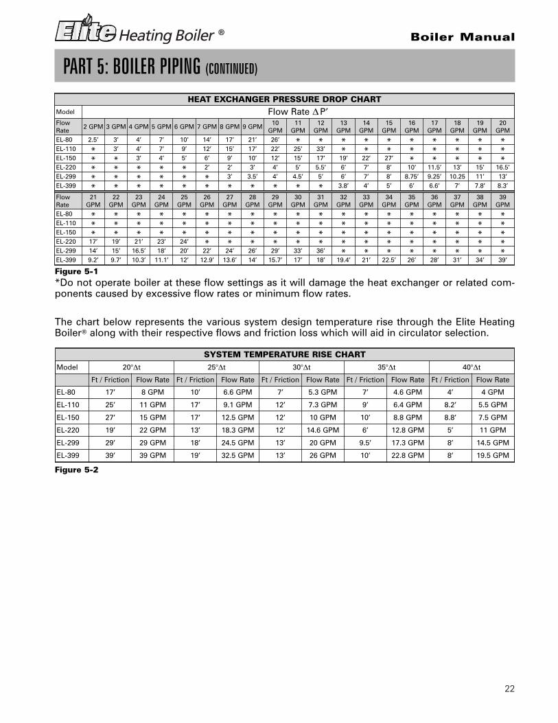
H. CIRCULATOR SIZING
The Elite Heating Boiler® Heat Exchanger has apressure drop that must be considered in yoursystem design. Refer to the table in Fig. 5-1 forpressure drop through the Elite Heating Boiler®
Heat Exchanger.
n CAUTIONThe Elite Heating Boiler® should not beoperated as a potable hot water heater. Itshould not be used as a direct hot water heatingdevice.
22
Boiler Manual
The chart below represents the various system design temperature rise through the Elite HeatingBoiler® along with their respective flows and friction loss which will aid in circulator selection.
*Do not operate boiler at these flow settings as it will damage the heat exchanger or related com-ponents caused by excessive flow rates or minimum flow rates.
PART 5: BOILER PIPING (CONTINUED)
HEAT EXCHANGER PRESSURE DROP CHARTModel Flow Rate Δ P’FlowRate
2 GPM 3 GPM 4 GPM 5 GPM 6 GPM 7 GPM 8 GPM 9 GPM10
GPM11
GPM12
GPM13
GPM14
GPM15
GPM16
GPM17
GPM18
GPM19
GPM20
GPMEL-80 2.5’ 3’ 4’ 7’ 10’ 14’ 17’ 21’ 26’ * * * * * * * * * *EL-110 * 3’ 4’ 7’ 9’ 12’ 15’ 17’ 22’ 25’ 33’ * * * * * * * *EL-150 * * 3’ 4’ 5’ 6’ 9’ 10’ 12’ 15’ 17’ 19’ 22’ 27’ * * * * *EL-220 * * * * * 2’ 2’ 3’ 4’ 5’ 5.5’ 6’ 7’ 8’ 10’ 11.5’ 13’ 15’ 16.5’EL-299 * * * * * * 3’ 3.5’ 4’ 4.5’ 5’ 6’ 7’ 8’ 8.75’ 9.25’ 10.25 11’ 13’EL-399 * * * * * * * * * * * 3.8’ 4’ 5’ 6’ 6.6’ 7’ 7.8’ 8.3’
FlowRate
21GPM
22GPM
23GPM
24GPM
25GPM
26GPM
27GPM
28GPM
29GPM
30GPM
31GPM
32GPM
33GPM
34GPM
35GPM
36GPM
37GPM
38GPM
39GPM
EL-80 * * * * * * * * * * * * * * * * * * *EL-110 * * * * * * * * * * * * * * * * * * *EL-150 * * * * * * * * * * * * * * * * * * *EL-220 17’ 19’ 21’ 23’ 24’ * * * * * * * * * * * * * *EL-299 14’ 15’ 16.5’ 18’ 20’ 22’ 24’ 26’ 29’ 33’ 36’ * * * * * * * *EL-399 9.2’ 9.7’ 10.3’ 11.1’ 12’ 12.9’ 13.6’ 14’ 15.7’ 17’ 18’ 19.4’ 21’ 22.5’ 26’ 28’ 31’ 34’ 39’
SYSTEM TEMPERATURE RISE CHART
Model 20°Δt 25°Δt 30°Δt 35°Δt 40°Δt
Ft / Friction Flow Rate Ft / Friction Flow Rate Ft / Friction Flow Rate Ft / Friction Flow Rate Ft / Friction Flow Rate
EL-80 17’ 8 GPM 10’ 6.6 GPM 7’ 5.3 GPM 7’ 4.6 GPM 4’ 4 GPM
EL-110 25’ 11 GPM 17’ 9.1 GPM 12’ 7.3 GPM 9’ 6.4 GPM 8.2’ 5.5 GPM
EL-150 27’ 15 GPM 17’ 12.5 GPM 12’ 10 GPM 10’ 8.8 GPM 8.8’ 7.5 GPM
EL-220 19’ 22 GPM 13’ 18.3 GPM 12’ 14.6 GPM 6’ 12.8 GPM 5’ 11 GPM
EL-299 29’ 29 GPM 18’ 24.5 GPM 13’ 20 GPM 9.5’ 17.3 GPM 8’ 14.5 GPM
EL-399 39’ 39 GPM 19’ 32.5 GPM 13’ 26 GPM 10’ 22.8 GPM 8’ 19.5 GPM
Figure 5-1
Figure 5-2

23
Boiler Manual
PART 5: BOILER PIPING (CONTINUED)
Figure 5-3 LP-293-JJ Rev. 7/31/09
I. FILL AND PURGE HEATING SYSTEM
• Attach the hose to balance and purge hoseconnector or drain valve and run hose tonearest drain.
• Close the other side of the balance and purgevalve or the shut off valve after the drain.
• Open the first zone balance and purge ordrain valve to let water flow out the hose. Ifzone valves are used, open the valves one ata time manually. (Note: You should checkzone valve manufacturer’s instructions prior
to opening valves manually, so as not todamage the zone valve.)
• Manually operate fill valve regulator. Whenwater runs out of the hose you will see asteady stream of water without bubbles.Close the balance and purge valve or drain tostop the water from flowing. Disconnect thehose and connect it to next zone to bepurged.
• Repeat this procedure for additional zones(one at time).
Flow Rate (GPM) 16 22 24 30 32 33 40 44 45 48 55 60 66 75 80 88 90 110 120 132 150 160 179 200 239Pipe Dia. (Inches) 2 2 2 2 2 2½ 2½ 2½ 2½ 2½ 2½ 2½ 2½ 3 3 3 3 4 4 4 4 4 4 4 5
MULTIPLE BOILER MANIFOLD PIPING
0
1
2
3
4
5
6
0 50 100 150 200 250
Pipe
Dia
met
er S
ize
(Inc
hes)
Combined Boiler Water Flow (GPM)
Mul ple Boiler Manifold Piping
The chart below represents the combined flowrates and pipe sizes when using multiple boilersto design the manifold system for the primarycircuit. To size, simply add up the number ofboilers and the required flow rates for the sys-tem design temperature.
Example: (5) EL-220 Elite Heating Boilers® with adesign of 20°Δt degree temperature rise witheach boiler having an individual flow rate of 22GPM. To correctly size the manifold feedingthese (5) Elite Heating Boilers you would need apipe size of 4”.
MULTIPLE BOILER MANIFOLD PIPING
Flow rate 30 50 60 85 90 100 120 150 170 180 200 210 240 250 255 300 340 350 400 425 510 595 680
Pipe Dia. 2” 2½” 2½” 3” 3” 3” 4” 4” 4” 4” 4” 4” 5” 5” 5” 5” 5” 5” 5” 5” 6” 6” 6”

24
Boiler Manual
PART 5: BOILER PIPING (CONTINUED)
Upon completion, make sure that the fill valveand zone valves are in the automatic position.You must also assure the purge and shut offvalves are in the open position.
1. Glycol in hydronic applications which isspecially formulated for this purpose includesinhibitors that prevent the glycol from attackingmetallic system components. Make certain thatthe system fluid is checked for the correctglycol concentration and inhibitor level.
2. The glycol solution should be tested at leastonce a year and as recommended by theglycol manufacturer.
3. Anti-freeze solutions expand more thanwater. For example a 50% by volume solutionexpands 4.8% in volume for a temperatureincrease from 32° F to 180° F, while waterexpands 3% with the same temperature rise.Allowances must be made for this expansionin the system design.
4. A 30% mixture of glycol will result in a BTUoutput loss of 15% with a 5% increase inhead against the system circulator.
5. A 50% mixture of glycol will result in a BTUoutput loss of 30% with a 50% increase inhead against the system circulator.
J. ZONING WITH ZONE VALVES
1. Connect the boiler to the system as shown inPiping Details (Part 5) when zoning with zonevalves. The primary/secondary piping shownensures the boiler loop will have sufficientflow. It also avoids applying the high head ofthe boiler circulator to the zone valves.
2. Connect DHW (domestic hot water) piping toindirect storage water heater as shown inPiping Details (Part 5).
K. ZONING WITH CIRCULATORS
1. Connect the boiler to the system when usingcirculator zoning as shown in the PipingDetails when zoning with circulators. NOTE:The boiler circulator cannot be used for azone. It must supply only the boiler loop.
2. Install a separate circulator for each zone.
3. Connect DHW (domestic hot water) piping toindirect storage water heater as shown in thePiping Details (Part 5).
L. MULTIPLE BOILERS
1. Connect multiple boilers as shown in thePiping Details (Part 5).
2. All piping shown is reverse return to assurebalanced flow throughout the connectedboilers.
3. Each connected boiler must have its owncirculator pump to assure adequate flow.
4. Connect DHW (domestic hot water) piping toindirect storage water heater as shown in thePiping Details (Part 5).
5. The system flow (secondary loop) must begreater than the boiler’s primary loop flow.
n CAUTIONFor installations that incorporate standing ironradiation and systems with manual vents at thehigh points. Follow the previous section andstarting with the nearest manual air vent, openthe vent until water flows out, then close thevent. Repeat the procedure, working your waytoward furthest air vent. It may be necessary toinstall a basket strainer in an older systemwhere larger amounts of sediment may bepresent. Annual cleaning of the strainer may benecessary.
n WARNINGUse only inhibited propylene glycol solutionswhich are specially formulated for hydronicsystems. Ethylene glycol is toxic and can attackgaskets and seals used in hydronic systems.Glycol mixtures should not exceed 50%.
n CAUTIONIt is highly recommended that you carefullyfollow the glycol manufacturer’s recommendedconcentrations, expansion requirements andmaintenance recommendations (pH additivebreakdown, inhibitor reduction, etc.). You mustcarefully calculate the additional friction loss inthe system as well as the reduction in heattransfer co-efficients.

25
Boiler Manual
A. INSTALLING EXHAUST VENT ANDINTAKE AIR VENT
B. GENERAL
1. Install the boiler venting system inaccordance with these instructions and withthe Nat ional Fuel Gas Code, ANSIZ223.1/NFPA 54, CAN/CGA B149, and/orapplicable provisions of local building codes.
2. This boiler is a direct vent appliance and islisted as a Category IV appliance withUnderwriters Laboratories, Inc.
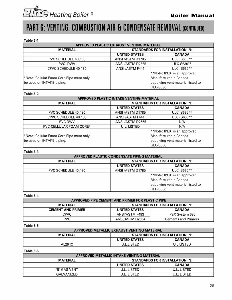
C. APPROVED MATERIALS FOR EXHAUSTVENT AND INTAKE AIR VENT
1. Use only Non Foam Core venting material orAL294C. See Tables 6-1 through 6-6 for allapproved venting material.
REQUIREMENTS FOR INSTALLATIONIN CANADA
1. Installations must be made with a vent pipesystem certified to ULC-S636. IPEX is anapproved vent manufacturer in Canadasupplying vent material listed to ULC-S636.Additionally you may use AL294C stainlesssteel venting to comply with Canadianrequirements.
2. The first three (3) feet of vent pipe from theappliance flue outlet must be readilyaccessible for visual inspection.
3. The components of the certified vent systemmust not be interchanged with other ventsystems or unlisted pipe / fittings.
Cellular foam core piping may be used on airinlet piping only.
PART 6: VENTING, COMBUSTION AIR & CONDENSATE REMOVAL
n WARNINGThis vent system will operate with a positivepressure in the pipe. Do not connect ventconnectors serving appliances vented by naturaldraft into any portion of mechanical draftsystems operating under positive pressure.Follow these venting instructions carefully. Failureto do so may result in substantial propertydamage, severe personal injury or death.
n WARNINGDo not use Cellular Foam Core Pipe in any portionof the exhaust piping from this boiler. Use ofFoam Core Pipe may result in severe personalinjury, death, or substantial property damage.
n WARNINGUse only the materials listed in Tables 6-1through 6-6 for the venting systems. Failure todo so could result in severe personal injury,death or substantial property damage.
n DANGERThe Elite Heating Boiler® must be vented asdetailed in this section. Verify that the exhaustand intake piping comply with theseinstructions regarding the venting system.Inspect finished combustion air intake andexhaust piping thoroughly to ensure all jointsare secure and airtight and comply with allapplicable code requirements, as well as withthe instructions provided in this manual.Failure to provide a properly installed ventsystem will cause severe personal injury ordeath.
26
Boiler Manual
PART 6: VENTING, COMBUSTION AIR & CONDENSATE REMOVAL (CONTINUED)
Table 6-1
**Note: IPEX is an approved*Note: Cellular Foam Core Pipe must only Manufacturer in Canada be used on INTAKE piping. supplying vent material listed to
ULC-S636
Table 6-2
**Note: IPEX is an approved*Note: Cellular Foam Core Pipe must only Manufacturer in Canada be used on INTAKE piping. supplying vent material listed to
ULC-S636
Table 6-3
**Note: IPEX is an approvedManufacturer in Canada supplying vent material listed to ULC-S636
Table 6-4
Table 6-5
Table 6-6
ULC- S636**N/A
PVC-CELLULAR FOAM CORE* U.L. LISTED N/A
PVC SCHEDULE 40 / 80 ANSI /ASTM D1785
PVC DWV ANSI /ASTM D2665CPVC SCHEDULE 40 / 80 ANSI /ASTM F441
ULC-S636**ULC- S636**
CEMENT AND PRIMERMATERIAL
APPROVED PLASTIC INTAKE VENTING MATERIAL MATERIAL STANDARDS FOR INSTALLATION IN:
UNITED STATES CANADAULC S636**
PVC SCHEDULE 40 / 80
APPROVED PLASTIC EXHAUST VENTING MATERIAL STANDARDS FOR INSTALLATION IN:
UNITED STATES CANADAMATERIAL
CPVC SCHEDULE 40 / 80 ANSI /ASTM D2665ANSI /ASTM F441
APPROVED PLASTIC CONDENSATE PIPING MATERIAL MATERIAL STANDARDS FOR INSTALLATION IN:
UNITED STATES CANADA
UNITED STATES CANADA
ANSI /ASTM D1785PVC SCHEDULE 40 / 80 ULC S636**PVC -DWV
STANDARDS FOR INSTALLATION IN:UNITED STATES CANADA
APPROVED METALLIC EXHAUST VENTING MATERIAL
PVCCPVC
MATERIAL STANDARDS FOR INSTALLATION IN:
ANSI /ASTM D1785 ULC S636**
AL294C U.L.LISTED U.L.LISTED
Cements and Primers
APPROVED PIPE CEMENT AND PRIMER FOR PLASTIC PIPE
IPEX System 636ANSI/ASTM D2564ANSI/ASTM F493
GALVANIZED U.L. LISTED U.L. LISTED
MATERIAL STANDARDS FOR INSTALLATION IN:UNITED STATES CANADA
APPROVED METALLIC INTAKE VENTING MATERIAL
"B" GAS VENT U.L. LISTED U.L. LISTED

27
Boiler Manual
PART 6: VENTING, COMBUSTION AIR & CONDENSATE REMOVAL (CONTINUED)
D. EXHAUST VENT AND INTAKE AIR VENTPIPE LOCATION
NOTE: SEE ADDITIONAL REQUIREMENTS FORMASSACHUSETTS IN THE BACK OF THIS MANUAL.
1. Determine exhaust vent location:
• Total length of vent may not exceed thelimits specified in Part 6 Section E.
• The vent piping for this boiler is approvedfor zero clearance to combustibleconstruction.
• See Venting Details within this section ofclearances for location of exit terminals ofdirect-vent venting systems.
• Avoid terminating exhaust vents nearshrubs, air conditioners or other objectsthat will obstruct the exhaust stream.
• The flue products coming from theexhaust vent will create a large plumewhen the boiler is in operation. Avoidventing in areas that wil l affectneighboring buildings or be consideredobjectionable.
• The boiler vent system shall terminate atleast 3 feet (0.9 m) above any forced airintake located within 10 ft (3 m). Note:this does not apply to the combustion airintake of a direct-vent appliance.
• Provide a minimum of 1 foot distancefrom any door, operable window, orgravity intake into any building.
• Provide a minimum of 1 foot clearancefrom the bottom of the exhaust above theexpected snow accumulation level. Snowremoval may be necessary to maintainclearance.
• Provide 4 feet horizontal clearance fromelectrical meters, gas meters, gasregulators, relief equipment, exhaust fansand inlets. In no case shall the exitterminal be above or below theaforementioned equipment unless the 4foot horizontal distance is maintained.
• Do not locate the boiler exhaust overpublic walkways where condensate coulddrip and/or freeze and create a nuisanceor hazard.
• When adjacent to a public walkway,locate exit terminals at least 7 feet abovegrade.
• Do not locate the exhaust directly underroof overhangs to prevent icicles fromforming.
• Provide 6 feet of clearance from theinside corner of vertical walls, chimneys,etc., as well as horizontal corners createdby roof overhangs.
2. Determine air intake vent locations.
• Provide 1 foot of clearance from thebottom of the intake air vent and the levelof maximum snow accumulation. Snowremoval may be necessary to maintainclearances.
• Do not locate the intake air vent in a parkingarea where machinery may damage thevent.
• Follow required minimum clearanceslocated in Fig. 6-3, 6-4, 6-5.
3. Determine location of Condensate Piping
This boiler is a high efficiency appliance,therefore the boiler produces condensate.Condensate is a by-product of the boilercombustion process. A condensate collec-tion system with an internal float switch
n WARNINGYou must not use “B” Vent in an exhaustapplication. ‘B’ vent is for intake applicationsonly. Failure to do so will result in serious injuryor death.
n WARNINGBoth exhaust and intake air vents must exitfrom the same side of the building to assurecorrect appliance operation.
n WARNINGYou must insert the provided intake and exhaustscreen at your vent terminations to preventblockage caused by birds or debris.

28
Boiler Manual
CAUTIONIt is very important that the condensate pipingbe no smaller than ¾” and you must use a teeat the condensate connection with the branchvertically up and open to the atmosphere so itwill not cause a vacuum that could obstruct theflow of condensate from the boiler. Thecondensate piping should also be properlysupported with pipe supports to preventsagging and to maintain the pitch of the piping.
4. Condensate Neutralization
The condensate from the boiler is slightlyacidic with a pH of 3.2 – 4.5 Heat TransferProducts, Inc. recommends neutralizing thecondensate with a Condensate Neutralizer Kitp/n 7450P-212 (EL-80/110/150/220) p/n 7350P-611 (EL-299/399) that can be added to yoursystem to avoid long term damage to thedrainage system and to meet local coderequirements. The neutralizer kit is connectedto the drain system and contains marblechips that will neutralize the pH level of thewater vapor. The neutralizer should bechecked at least once a year and the marblechips should be replenished if necessary.When replacing the marble chips, theyshould be no smaller than ½” to avoidblockage in condensate piping. (Refer to Fig.6-1 and 6-2 for piping of the Condensateneutralizer.)
PART 6: VENTING, COMBUSTION AIR & CONDENSATE REMOVAL (CONTINUED)
monitors the condensate level to prevent itfrom backing up into the combustion sys-tem. There is a ¾” sweat connection provid-ed to connect the outlet of the collectionsystem to a drain or condensate pump. (SeeTable 6-3 for approved condensate pipingmaterial)

29
Boiler Manual
PART 6: VENTING, COMBUSTION AIR & CONDENSATE REMOVAL (CONTINUED)
CAUTIONThe condensate line must remain unobstructed,allowing free flow of condensate. If condensateis allowed to freeze in the line or if the line isobstructed in any other manor, condensate canexit from the boiler tee, resulting in potentialwater damage to property.
NOTICEWhen installing a condensate pump, select oneapproved for use with condensing boilers andfurnaces. The pump should have an overflowswitch to prevent property damage fromcondensate spillage.Condensate from the Elite Heating Boiler® willbe slightly acidic (typically with a pH from 3.2 to4.5). Install a neutralizing filter if required bylocal codes.
Fig. 6-1
Fig. 6-2 LP-293-R Rev. 7/08/09
NOTE: To clean out condensate collector,blow water into collector to remove anyforeign matter that may block thecondensate line.
n WARNINGWhen servicing is complete, you mustmake sure this cap is replaced securely.Failure to do so will cause venting issuesthat will result in serious injury or death.

30
Boiler Manual
Fig. 6-3 Multiple Vents
PART 6: VENTING, COMBUSTION AIR & CONDENSATE REMOVAL (CONTINUED)
Fig. 6-5 Multiple Stainless Steel Horizontal Vent Kit Installation – Front View
Multiple “V” Series Vents
Location of exit terminals of mechanical draft and direct-vent venting systems.(Reference: National Fuel Gas Code ANSI Z223.1/NFPA 54 2002).
Fig. 6-4 Multiple Vent Spacing**Note: Exhaust must extend out 1 foot. There should be no more than 2 vents and 2 intakes then a space of 36” to thenext set of vents.*Note: There must be a minimum of 36” spacing between every 2 kit grouping.
Fig. 6-6 Multiple Concentric VentSpacing – Vertical
Fig. 6-7 Multiple Concentric VentSpacing – Horizontal

31
Boiler Manual
PART 6: VENTING, COMBUSTION AIR & CONDENSATE REMOVAL (CONTINUED)
E. EXHAUST VENT AND INTAKE AIR VENTSIZING
1. The exhaust vent and intake air vent pipesare 3" for the Elite EL-80/110/155/220, and 4"for the EL-299/399.
2. The total combined equivalent length ofexhaust vent and intake air pipe should notexceed 200 feet.
a. The equivalent length of elbows, tees,and other fittings are listed in the FrictionLoss Table 6-8.
*Friction loss for long radius elbow is 1 foot less.
b. For example: If the exhaust vent has twoshort 90° elbows and 10 feet of PVC pipewe will calculate:
Exhaust Vent Pipe Equivalent Length = (2x5)+10=20 feet
Further, if the intake air vent pipe has twoshort 90° elbows, one 45° elbow and 10feet of PVC pipe, the following calculationapplies:
Intake Air Vent Pipe Equivalent Length = (2x5)+1+10=21 feet
c. The intake air vent pipe and the exhaustvent are intended to penetrate the samewall or roof of the building.
d. You should keep an equivalent lengthbetween the intake air vent pipe and theexhaust vent. The minimum combinedequivalent length is 16 to 32 maximumcombined equivalent feet.
e. The size of the venting can also bereduced in order to accommodate anexisting vent sizes.
When reducing down to a 2” vent from a 3” ventor down to a 3” vent from 4”, the combinedlength shall not exceed an equivalent of 100feet.
F. LONGER VENT RUNS
1. The maximum combined equivalent lengthcan be extended by increasing the diameterof both exhaust vent and intake air vent pipeequally. However, the transitions shouldbegin a minimum of 16 to 32 maximumcombined equivalent feet from the boiler onboth the intake and exhaust equally.
a. The maximum equivalent length for theincreased diameter vent pipes is 275 feet,which includes the combined 32 feet fromthe boiler, 16 ft. (inlet) + 16 ft. (exhaust) =32 ft. combined with transition total of 245ft. upsize piping for longer vent runs.
G. EXHAUST VENT AND INTAKE AIR PIPEINSTALLATION
1. Use only solid PVC, or CPVC schedule 40 or80 pipe and AL294C Stainless Steel. FOAMCORE PIPING IS ONLY ALLOWED FORINTAKE PIPING.
2. Remove all burrs and debris from joints andfittings.
3. All joints must be properly cleaned, primed,and cemented. Use only cement and primerapproved for use with the pipe material.Refer to the Venting Table 6-4.
Friction Loss Equivalent forStainless or Plastic Piping and Fittings
Fitting Description 3" 4" 6"
90° elbow short radius 5' 5' 3'
90° elbow long radius 4' 4' 3'
45° elbow 3' 3' 2'
Coupling 0' 0' 0'
Tee (intake only) 0' 0' 0'
V Series Vent Kit 1' 1' 1'
AL29 4C Vent Terminal 1' 1' 1'
Pipe (All materials) 1’ 1’ 1’
Table 6-8
Vent Transition FittingSize Reducing Coupling Final Vent Size
3" venting 4" x 3" 4"
4" venting 6" x 4" 6"
6" venting 8" x 6" 8"
Table 6-9
NOTE: EXTENDED VENTRUNS WHEN TRANSITIONINGTO A LARGER DIAMETERMUST ALWAYS TAKE PLACEIN A VERTICAL POSITIONTO PREVENT CONDENSATEBLOCKAGE.

32
Boiler Manual
PART 6: VENTING, COMBUSTION AIR & CONDENSATE REMOVAL (CONTINUED)
4. Horizontal lengths of exhaust vent must slopeback towards the boiler not less than ¼" perfoot to allow condensate to drain from thevent pipe. If the exhaust pipe must be pipedaround an obstacle that results in the creationof a low point, condensate will collect in thislow point and form a blockage. Thiscondensate must be drained away using afield-installed condensate drain assembly. Allvent pipes must be glued, properlysupported and the exhaust must be pitcheda minimum of ¼” per foot back to the boilerto allow drainage of condensate. Thecondensate drain piping should be aminimum of ¾” PVC rigid piping, pitched at aminimum of ¼” per foot away from the boiler.(See Fig. 6-1, 6-2)
5. All piping must be fully supported. Use pipehangers at a minimum of 4 foot intervals toprevent sagging of the pipe wherecondensate may form. When placing supportbrackets on vent piping, the first bracket mustbe within 1 foot of the appliance and thebalance at 4 foot intervals on the vent pipe.The boiler venting must be readily accessiblefor visual inspection for the first three feet ofthe boiler.
6. Do not use the boiler to support any piping.
7. A screened straight coupling is provided withthe boiler for use as an outside exhausttermination.
8. A screened inlet air tee is provided with theboiler to be used as an outside intaketermination.
H. HEATER REMOVAL FROM A COMMONVENT SYSTEM
At the time of removal of an existing heater, thefollowing steps shall be followed with eachappliance remaining connected to the commonventing system placed in operation, while theother appliances remaining connected to com-mon venting system are not operating.
1. Seal any unused openings in the commonventing system.
2. Visually inspect the venting system for propersize and horizontal pitch to determine if thereis blockage, leakage, corrosion or other defi-ciencies that could cause an unsafe condition.
3. If practical, close all building doors, windowsand all doors between the space in which theappliance remains connected to the commonventing system located and other spaces inthe building. Turn on clothes dryers and anyappliances not connected to the commonventing system. Turn on any exhaust fans,such as range hoods and bathroom exhausts,at maximum speed. Do not operate a summerexhaust fan. Close all fireplace dampers.
4. Place in operation the appliance beinginspected. Follow the lighting instructions.Adjust the thermostat so the appliance willoperate continuously.
5. Test for spillage at the draft hood reliefopening after 5 minutes of main burneroperation. Use the flame of a match or candleor smoke from a cigarette.
6. After it has been determined that eachappliance remaining connected to commonventing system properly vents when tested asoutlined, return doors, windows, exhaust fans,fireplace dampers and any other gas burningappliance to their previous condition of use.
7. Any improper operation of the commonventing system should be corrected so theinstallation conforms with the National FuelGas Code, ANSI Z223.1. When resizing anyportion of the common venting system, thecommon venting system should be resized toapproach the minimum size as determinedusing the appropriate tables in Appendix G inthe National Fuel Gas Code, ANSI Z 223.1
Note: For Canadian Installations, it is requiredthat Non Metallic Vent Installations conform toULC S636. Where plastic venting is not allowed,HTP recommends AL294C Stainless SteelVenting be used for Exhaust venting installa-tions and “B” vent for intake air.
Please refer to 6-7 below for U.L. ApprovedStainless Steel Vent Adapters.
n WARNINGAll joints of positive pressure vent systemsmust be sealed completely to prevent leakageof flue products into the living space.

33
Boiler Manual
I. DIAGRAMS FOR SIDEWALL VENTING
1" MIN.
INSERT INLET/EXHAUST SCREENSPROVIDED INTO EACH END OF TEE
INSERT INLET/EXHAUST SCREENSPROVIDED INTO STRAIGHT COUPLING
EXTERIOR WALL
ALL HORIZONTAL TEE
VIEWRIGHT SIDE
AND VERTICAL PIPING
SUPPORT BRACKETSMUST BE USED ON
STRAIGHTCOUPLING
12" MIN.
IS GREATER.
MAINTAIN 12" MINIMUM
CLEARANCE ABOVE HIGHEST
ANTICIPATED SNOW LEVELOR GRADE, WHICHEVER
TEEAIR INTAKE
TOP VIEW
VENT
EXHAUSTVENT
COUPLINGSTRAIGHT
INLET/EXHAUST SCREEN
12" MIN.
1" MIN.
Figure 6-9 LP-293-D Rev. 9/22/08
Figure 6-10 LP-293-E Rev. 9/22/09
SIDEWALL VENTING W/TEE (INTAKE)AND COUPLING (EXHAUST)
VIEW
EXTERIOR WALL
AND VERTICAL PIPING
RIGHT SIDE
SUPPORT BRACKETSMUST BE USED ONALL HORIZONTAL
VENT KIT
WHICHEVER IS GREATER.
MAINTAIN MIN.
12" CLEARANCE ABOVEHIGHEST ANTICIPATED
SNOW LEVEL OR GRADE
VENT
TOP VIEW
VENTINTAKE AIR
EXHAUST
VENT KIT
SIDEWALL VENTING WITH KITSIDEWALL VENTING WITH KIT
PART 6: VENTING, COMBUSTION AIR & CONDENSATE REMOVAL (CONTINUED)
n WARNINGAll vent pipes must be glued, properly supported and the exhaust must be pitched a minimum of a ¼" perfoot back to the heater (to allow drainage of condensate). When placing support brackets on vent piping,the first bracket must be within 1 foot of the appliance and the balance at 4 foot intervals on the vent pipe.The boiler venting must be readily accessible for visual inspection for the first three feet from the boiler.
NOTE: Vent piping should be 12" over anticipated maximum snow level.

34
Boiler Manual
Figure 6-11 LP-293-F Rev. 2/23/09
J. DIAGRAM FOR VERTICAL VENTING
24" MIN.
WHICHEVER IS GREATER
12" OVER MAXIMUMSNOW LEVEL OR 24"
10' - 0" MIN.
SUPPORT BRACKETSMUST BE USED ONALL HORIZONTAL
AND VERTICAL PIPING
INTAKE AIRVENT (TEE)
EXHAUST VENT(STRAIGHT COUPLING)
EXTERIOR WALL
RIGHT SIDEVIEW
ROOF VENT WITH TEE (INTAKE)AND COUPLING (EXHAUST)
PART 6: VENTING, COMBUSTION AIR & CONDENSATE REMOVAL (CONTINUED)
n WARNINGAll vent pipes must be glued, properly supported and the exhaust must be pitched a minimum of a ¼" perfoot back to the heater (to allow drainage of condensate). When placing support brackets on vent piping,the first bracket must be within 1 foot of the appliance and the balance at 4 foot intervals on the vent pipe.The boiler venting must be readily accessible for visual inspection for the first three feet from the boiler.

35
Boiler Manual
Figure 6-12 VT-A Rev. 8/28/09
K. DIAGRAM FOR HORIZONTAL VENTING
PART 6: VENTING, COMBUSTION AIR & CONDENSATE REMOVAL (CONTINUED)
n WARNINGAll vent pipes must be glued, properly supported and the exhaust must be pitched a minimum of a ¼" perfoot back to the heater (to allow drainage of condensate). When placing support brackets on vent piping,the first bracket must be within 1 foot of the appliance and the balance at 4 foot intervals on the vent pipe.The boiler venting must be readily accessible for visual inspection for the first three feet from the boiler.
A. FOR EVERY 1" OF OVERHANG THE EXHAUST VENT MUST BE LOCATED 1" VERTICAL BELOW OVERHANG
(OVERHANG MEANS TOP OF BUILDING STRUCTUREAND NOT TWO ADJACENT WALLS (CORNER OF BUILDING)).
B. 12" SEPARATION BETWEEN BOTTOM OF EXHAUST OUTLET AND TOP OF AIR INTAKE (TYP.)
C. MAINTAIN 12" MINIMUM CLEARANCE ABOVE HIGHEST ANTICIPATED SNOW LEVEL OR GRADE WHICHEVER IS
GREATER (TYP.)
D. MINIMUM 12" BETWEEN VENTS WHEN INSTALLING MULTIPLE VENTS
E. 12 " MIN. BEYOND INTAKE
A
D
C
MULTIPLE BOILERS
SINGLE BOILER
RIZONTAL VENTING
E

36
Boiler Manual
PART 6: VENTING, COMBUSTION AIR & CONDENSATE REMOVAL (CONTINUED)
Figure 6-13 LP-293-T Rev. 9/24/09
24" MIN.
INTAKE AIR
AND VERTICAL PIPING
EXHAUST VENT(STRAIGHT COUPLING)
SUPPORT BRACKETSMUST BE USED ONALL HORIZONTAL
12" OVER MAXIMUM SNOW LEVELOR 24" WHICHEVER IS GREATER.
WHICHEVER IS GREATER.
MAINTAIN MIN. 12"
CLEARANCE ABOVE
HIGHEST ANTICIPATED
SNOW LEVEL OR GRADE,
UNBALANCED FLUE / VERTICAL VENT
n WARNINGYou are only allowed to install an unbalanced vent system when the exhaust vent is in the VerticalPosition ONLY.
n WARNINGAll vent pipes must be glued, properly supported and the exhaust must be pitched a minimum of a ¼" perfoot back to the heater (to allow drainage of condensate). When placing support brackets on vent piping,the first bracket must be within 1 foot of the appliance and the balance at 4 foot intervals on the vent pipe.The boiler venting must be readily accessible for visual inspection for the first three feet from the boiler.
L. DIAGRAM FOR UNBALANCED FLUE/VERTICAL VENT

37
Boiler Manual
PART 7: GAS PIPING
A. GAS CONNECTION
The gas supply shall have a maximum inletpressure of less than 14" w.c. (3.5 kPa), and aminimum of 3.5" w.c. (.87 kPa). The entire pipingsystem, gas meter and regulator must be sizedproperly to prevent pressure drop greater than0.5" (.12 kPa) as stated in the National Fuel GasCode. This information is listed on the ratinglabel.
The gas connection on the Elite Heating Boiler®
is 3/4” for the EL-80/110/150 and 1” for theEL-220/299/399. It is mandatory that this fitting isused for connection to a field fabricated drip legas shown in the illustration above per theNational Fuel Gas Code. You must ensure thatthe entire gas line to the connection at the EliteHeating Boiler® is no smaller than the unit sup-plied connection. Once all the inspections have
n WARNINGFailure to follow all precautions in this sectioncould result in fire, explosion or death!
n WARNINGIt is very important that you are connected tothe type of gas as noted on the rating plate.“LP” for liquefied petroleum, propane gas or,“Nat” natural or city gas. You must not do a gasconversion on this boiler without an approvedgas conversion kit. All gas connections must beapproved by the local gas supplier, or utility inaddition to the governing authority, prior toturning the gas supply on.
UNION
GAS SUPPLY
MANUAL SHUT OFF(FIELD SUPPLIED)
DRIP LEG
PIPING SUPPORT
been performed, the piping must be leak tested.If the leak test requirement is a higher test pres-sure than the maximum inlet pressure, you mustisolate the Elite Heating Boiler® from the gasline. In order to do this, you must shut the gasoff using factory and field-installed gas cocks.This will prevent high pressure. Failure to do somay damage the gas valve. In the event the gasvalve is exposed to a pressure greater than ½PSI, 14" w.c. (3.5 kPa), the gas valve must bereplaced. Never use an open flame (match,
lighter, etc.) to check gas connections.
B. GAS PIPING
1. Run the gas supply line in accordance with allapplicable codes.
2. Locate and install manual shutoff valves in ac-cordance with state and local requirements.
3. In Canada, the Manual Shutoff must beidentified by the installing contractor.
4. It is important to support gas piping as theunit is not designed to structurally supportlarge amount of weight.
5. Purge all gas lines thoroughly to avoid startup issues with air in the lines.
6. Sealing compound must be approved for gasconnections. Care must be taken whenapplying compound to prevent blockage orobstruction of gas flow which my effect theoperation of the unit.
NominalIron Pipe Internal Length of Pipe (Feet)Size Diameter(inches) (inches) 10 20 30 40 50 60 703/4 .824 278 190 152 130 115 105 96 BTU'S1 1.049 520 350 285 245 215 195 180 PER
1 1/4 1.380 1,050 730 590 500 440 400 370 HOUR1 1/2 1.610 1,600 1,100 890 760 670 610 560
}x1,000
80 90 100 125 150 175 2003/4 .824 90 84 79 72 64 59 55 BTU'S1 1.049 170 160 150 130 120 110 100 PER
1 1/4 1.380 350 320 305 275 250 225 210 HOUR1 1/2 1.610 530 490 460 410 380 350 320
}x1,000

38
Boiler Manual
PART 7: GAS PIPING (CONTINUED)
C. CHECK INLET GAS PRESSURE
The gas valve is equipped with an inlet gas pres-sure tap that can be used to measure the gaspressure to the unit. To check gas pressure, per-form the steps listed below:1. Before you connect to the inlet pressure, you
must shut off the gas and electrical power tounit.
2 Loosen the pressure tap with a small screw-driver. Refer to Figures 7-2 for location.
3. Each unit is equipped with a needle valve thatwill accept a 5/16 ID hose to connect to adigital manometer or liquid gauge tomeasure incoming pressure from 0-35” w.c.See Figure 7-1.
4. Turn on the Gas and Power up the unit.5. Put the unit into manual test mode (Details on
test mode are in Part 11 Section B). In servicemode, monitor pressure to assure it does notdrop below 1 inch from its idle reading. If GasPressure is out of range or pressure drop isexcessive, contact the gas utility, gassupplier, qualified installer or service agencyto determine correct action that is needed toprovide proper gas pressure to the unit. IfGas Pressure is within normal range proceedto Step 6.
6. Exit test mode, then turn power off and shutoff gas supply at the manual gas valve before
disconnecting the hose from the gasmonitoring device. Tighten the screw on thepressure tap tightly and turn gas on andchecks for leaks with soapy solution.
It is recommended that a soapy solution be usedto detect leaks. Bubbles will appear on the pipeto indicate a leak is present. The gas piping mustbe sized for the proper flow and length of pipeto avoid pressure drop. The gas meter and thegas regulator must be properly sized for thetotal gas load. If you experience a pressure dropgreater than 1" w.c. (.87 kPa), the meter, regula-tor or gas line may be undersized or in need ofservice. You can attach a manometer to theincoming gas drip leg by removing the cap andinstalling the manometer. The gas pressuremust remain between 3.5" (.87 kPa) and 14" (3.5kPa) during stand-by (static) mode and while inoperating (dynamic) mode. If an in-line regula-tor is used, it must be a minimum of 10 feet fromthe Elite Heating Boiler®. It is very importantthat the gas line is properly purged by the gassupplier or utility. Failure to properly purge thelines or improper line sizing, will result in igni-tion failure. This problem is especially notice-able in NEW LP installations and also in emptytank situations. This situation can also occurwhen a utility company shuts off service to anarea to provide maintenance to their lines. Thisgas valve must not be replaced with a conven-tional gas valve under any circumstances.
n WARNINGNever use an open flame (Match or Lighter) tocheck for Gas leaks. Use A soapy solution totest gas connection for leaks. Failure to usesoapy solution test or check gas connection forleaks can cause substantial property damage,severe personal injury or death.
NOTICECSA or UL listed Flexible gas connections canbe used when installing The Elite HeatingBoiler®. Flexible gas connections have differentcapacities and must be sized correctly for theconnected boiler firing rates. Consult with theflex line supplier to assure the line size isadequately sized for the job. Follow local codesfor proper installation and service requirements.
Fig. 7-1 LP-205-W Rev. 7/24/09

39
Boiler Manual
PART 7: GAS PIPING (CONTINUED)
D. ELITE HEATING BOILER® GAS VALVE
PRESSURE TAP
GAS VALVE
GAS OUTLET
GAS SHUT-OFF
GAS INLET
GAS OUTLET
PRESSURE TAP
VALVE
GAS INLET
OFFSET ADJUSTMENTCAUTION: DO NOT REMOVETHIS SCREW OR ATTEMPT TOMAKE ANY ADJUSTMENT TOTHIS SCREW WITHOUT A COMBINATION ANALYZER
A
DETAIL A SCALE 1 : 1
THROTTLE ADJUSTERNOTE: IF FOR ANY REASON THE THROTTLE NEEDS TO BE ADJUSTED,IT IS VERY IMPORTANT THAT A"COMBUSTION ANALYZER" BE USEDTO ENSURE SAFE AND PROPER OPERATION. TURN THE ADJUSTER TOTHE (+) TO INCREASE THE GAS OR (-)TO DECREASE THE GAS SUPPLY.THIS ADJUSTMENT COULD AFFECTCO/CO% LEVELS. MAKE SURE THELEVELS CORRESPOND TO THE CHARTIN COMBUSTION SETTINGS (FIG. 10-1)
ELITE GAS VALVE
Fig. 7-2 LP-293-V Rev. 7/24/09

40
Boiler Manual
PART 8: FIELD WIRING
A. INSTALLATION MUST COMPLY WITH:
1. National Electrical Code and any othernational, state, provincial or local codes orregulations.
2. In Canada, CSA C22.1 Canadian ElectricalCode Part 1, and any local codes.
B. FIELD WIRING
All connections made to the Elite HeatingBoiler® in the field are done inside the electricaljunction box located on the side of the unit. Theelectrical junction box is located on the left sideof Elite Heating Boiler®. Multiple knockout loca-tions are available to route field wires into andout of the electrical junction box.
The control used in the Elite Heating Boiler®
series of boilers is capable of directly controlling2 pumps when in standard mode and 3 pumpswhen configured as a cascade master boiler.When configured as a standard unit, each pumpoutput can provide a maximum of 3 amps at 120volts. If pumps used require more than thisamount of power, an external contactor ormotor starter is needed. If the boiler is config-ured as a cascade master, the system pump out-put is a dry contact output capable of switching5 amps at 120 volts in addition to the boilerpump and DHW pump outputs sourcing 3 ampseach.
The electrical junction box has separate, clearlymarked terminal strips for line voltage and lowvoltage wiring. Special jacks are provided fortrouble-free cascade system wiring using stan-dard CAT3 or CAT5 patch cables.
C. LINE VOLTAGE WIRING FORSTANDARD BOILER
1. Connect the incoming power wiring to theline voltage terminal strip in the electricaljunction box at terminals 120V, Neutral,Ground (shown in figure 8-1.)
2. A line voltage fused disconnect switch maybe required to be externally mounted andconnected according to local codes that mayapply.
3. Connect the central heating pump as shownin Figure 8-1 to the terminals marked BOILERHOT, BOILER NEUT, BOILER GND. Theconnections shown are suitable for amaximum continuous pump draw of 3 ampsat 120 volts. If a the pump requires morecurrent or voltage other than the 120 voltssupplied, an external motor starter orcontactor will be required.
4. If using DHW, connect the domestic hot waterpump as shown in Figure 8-1 to the terminalsmarked DHW HOT, DHW NEUT, DHW GND.The connections shown are suitable for amaximum continuous pump draw of 3 ampsat 120 volts. If a pump that requires morecurrent or voltage other than 120 voltssupplied, an external motor starter orcontactor will be required.
n WARNINGELECTRICAL SHOCK HAZARD — For yoursafety, turn off electrical power supply at serviceentrance panel before making any electricalconnections to avoid possible electric shockhazard. Failure to do so can cause severepersonal injury or death.
NOTICEWiring must be N.E.C. Class 1.If original wiring as supplied with boiler must bereplaced, use only TEW 105 °C wire orequivalent.Boiler must be electrically grounded as requiredby National Electrical Code ANSI/NFPA 70 —latest edition.

41
Boiler Manual
PART 8: FIELD WIRING (CONTINUED)
D. LOW VOLTAGE CONNECTIONS FORSTANDARD BOILER
1. All low voltage cables should enter theelectrical junction box through the providedknock out holes as shown below.
2. Connect all low voltage field devices to thelow voltage terminal strip located in theelectrical junction box (shown in Figure 8-1).
Knock out locationsfor low voltage connections toelectrical junction box.

42
Boiler Manual
PART 8: FIELD WIRING (CONTINUED)
Elite Heating Boiler® CONTROL
Fig. 8-1 LP-293-NN Rev. 7/13/09
E. THERMOSTAT
1. Connect the room thermostat to theterminals marked THERMOSTAT in theelectrical junction box (shown in figure 8-1)Alternately, any dry contact closure acrossthese terminals will cause the Elite Heating
Boiler® unit to run. Caution should be used toensure neither of the terminals becomeconnected to ground.
2. Mount the thermostat on an inside wall ascentral as possible to the area being heated,but away from drafts or heat producing

43
Boiler Manual
PART 8: FIELD WIRING (CONTINUED)
devices such as television sets that couldinfluence the ability of the thermostat tomeasure room temperature.
3. If the thermostat is equipped with ananticipator and it is connected directly to theElite Heating Boiler®, the anticipator should beset at .1 amps. If the thermostat is connectedto other devices, the anticipator should be setto match the power requirements of thedevice it is connected to. See the instructionmanual of the connected devices for furtherinformation.
F. OUTDOOR SENSOR
1. There is no connection required if an outdoorsensor is not used in this installation.
3. Use a minimum 22 AWG wire for runs of 100feet or less and minimum 18 AWG wire forruns of up to 150 feet.
4. Mount the outdoor sensor on an exteriorsurface of the building, preferably on thenorth side in an area that will not be affectedby direct sunlight and will be exposed tovarying weather conditions. NOTE: Followinstructions provided with the sensor forcorrect mounting instructions.
G. INDIRECT SENSOR
1. There is no indirect sensor connectionrequired if an indirect water heater is notused in the installation.
2. The Elite Heating Boiler® will operate anindirect fired water heater with either athermostat type aquastat installed in theindirect tank or an HTP 7250P-325 tanksensor. When a tank sensor is used, the EliteHeating Boiler® control will automaticallydetect its presence and a demand for heatfrom the indirect water heater will begenerated when the tank temperature fallsbelow the user set point by more than theuser selectable offset. The demand willcontinue until the sensor measures that theindirect water heater temperature is abovethe set point.
3. Connect the indirect tank sensor (7250P-325)to the terminals marked DHW SENSOR(shown in figure 8-1) in the electrical junctionbox.
H. OPTIONAL 0-10 VOLT BUILDINGCONTROL SIGNAL
1. A signal from a building management systemmay be connected to the Elite Heating Boiler®
to enable remote control. This signal shouldbe a 0-10 volt positive-going DC signal.When this input is enabled using the installermenu, a building control system can be usedto control either the set point temperature orthe heat output of the Elite Heating Boiler®.The control interprets the 0-10 volt signal asfollows; when the signal is between 0 and 1volt, the Elite Heating Boiler® will be in stand-by mode, not firing. When the signal risesabove 1 volt, the Elite Heating Boiler® willignite. As the signal continues to rise towardsits maximum of 10 volts, the Elite HeatingBoiler® will increase either in set pointtemperature or firing rate depending on thesetting of function 17 in the installer menu.See Part 11 for details on the setting offunctions 16 and 17 for this option.
2. Connect a building management system orother auxiliary control signal to the terminalsmarked 0-10 VOLT + and 0-10 VOLT – in theelectrical junction box (shown in figure 8-1)Caution should be used to ensure that the 0-10 VOLT + connection does not becomeconnected to ground.
I. OPTIONAL UL353 LOW WATER CUT-OFFINTERFACE KIT
If an optional UL 353 Low Water Cut-Off (LWCO)Interface Kit is used, the control box of the kitshould be mounted to the left side of the boilercabinet near the low water cut-off probe, whichis located on the outlet nipple of the boiler.
Follow the complete instructions included in thekit for proper installation.
J. WIRING OF CASCADE SYSTEMCOMMUNICATION BUS
1. Use standard CAT3 or CAT5 computernetwork patch cables to connect the
CAUTIONCaution should be used to ensure neither ofthese terminals become connected to ground.

44
Boiler Manual
UNUSED COMMUNICATION"B" JACK AVAILABLE TO CONNECT TO VISION 2 WITH VISION 2/3 CAT 5 ADAPTER CABLE(P/N 7350P-612)
UNUSED COMMUNICATION"B" JACK AVAILABLE TOCONNECT TO VISION 2
7350P-612ADAPTER CABLE
VISION 2
Fig. 8-2 LP-293-GG Rev. 8/11/09
PART 8: FIELD WIRING (CONTINUED)
communication bus between each of theboilers. These cables are readily available atany office supply, computer, electronic,department or discount home supply store invarying lengths. If you possess the skills youcan also construct custom length cables.
2. It is recommended to use the shortest lengthcable that will reach between the boilers andcreate a neat installation. Do not rununprotected cables across the floor wherethey may become wet or damaged. Avoidrunning communication cables parallel andclose to or against high voltage (120 volt orgreater) wiring. HTP recommends that themaximum length of communication bus
cables not exceed 200 feet.
3. Route the communication cables throughone of the knockouts in the cabinet.
4. Connect the boilers in a daisy chainconfiguration as shown below. It is best towire the boilers using the shortest wire runsrather than trying to wire them in the orderthat they are addressed. The communicationbus jacks on the customer connection panelare interchangeable so you can use eitherone or both in any order to connect the cable.If you have connected the boilers to eachother properly, two of the boilers will haveone open connection port on them.

45
Boiler Manual
PART 8: FIELD WIRING (CONTINUED)
Elite Heating Boiler® Cascade Master
Fig. 8-3 LP-293NN Rev. 7/13/09
ELITE CASCADE MASTER PUMP ANDSENSOR WIRING
1. Connect the system pump hot wire to theterminal marked SYS PUMP.
2. Connect the system pump neutral to theBOILER NEUT terminal and the pump groundwire to the BOILER GND terminal.
3. Connect a jumper wire from the 120 VOLTterminal to the SYS PUMP PWR terminal.
4. Connect the boiler pump to the terminalsmarked BOILER HOT, BOILER NEUT, and
BOILER GND
5. Connect the system pipe sensor to theterminals marked SYS SENSOR.
6. Connect the outdoor sensor (if used) to theterminals marked OUTDR. SEN
7. Connect the signal to start the system to theterminals marked THERMOSTAT.
NOTE: This signal can come from a roomthermostat or a dry contact closure. Nopower of any voltage should be fed intoeither of these terminals.

46
Boiler Manual
Elite Heating Boiler® Cascade Follower
Fig. 8-4 LP-293-NN Rev. 7/13/09
PART 8: FIELD WIRING (CONTINUED)
ELITE CASCADE FOLLOWER PUMPAND SENSOR WIRING
1. Connect the boiler pump to the terminalslabeled BOILER HOT, BOILER NEUT, BOILERGND.
2. If you are using an indirect fired water tankconnected directly to the follower boilerconnect the pump for it to the DHW, HOTDHW NEUT, and DHW GND terminals.
An alarm bell or light can be connected to thealarm contacts of the follower boiler. The nor-mally closed alarm contact may be used to turna device off if the boiler goes into lockout mode.The alarm contacts are rated 5 amps at 120 VAC.
To connect an alarm device, connect the power
for the device to the ALARM COM terminal.Connect the alarm device hot wire to theALARM NO terminal. Connect the neutral orreturn of the alarm device to the neutral orreturn of the power for the alarm device.
To connect a device that should be powered offduring a boiler lockout condition, follow thesame instructions as above except use theALARM NC terminal rather than the ALARM NOterminal.
Note that in a cascade system the alarm outputof the boiler addressed as #1 will also be activeif the master boiler has a lockout condition. Thealarm output of boilers addressed as 2-7 willonly activate an alarm if a lockout conditionoccurs on that specific boiler.

47
Boiler Manual
PART 8: FIELD WIRING (CONTINUED)
Fig. 8-5 LP-293-J Rev. 10/1/09

48
Boiler Manual
PART 8: FIELD WIRING (CONTINUED)
Fig. 8-5 LP-293-J Rev. 1/14/10

49
Boiler Manual
PART 9. START-UP PREPARATIONTo assure good extended service life, it isrecommended that you test your water qualityprior to installation. Listed below are someguidelines.
A. CHECK/CONTROL WATER CHEMISTRY
Water pH between 6.0 and 8.01. Maintain boiler water pH between 6.0 and 8.0.
Check with litmus paper or have it chemicallyanalyzed by a water treatment company.
2. If the pH differs from above, consult local watertreatment company for treatment needed.
Hardness less than 7 grains.1. Consult local water treatment companies for
unusually hard water areas (above 7 grainshardness).
Chlorine concentration less than 200 ppm1. Using chlorinated fresh water should be
acceptable since drinking water chlorinelevels are typically less than 5 ppm.
2. Do not connect the boiler to directly heat aswimming pool or spa water.
3. Do not fill boiler or operate with watercontaining chlorine in excess of 200 ppm.
Clean system to remove sediment1. You must thoroughly flush the system
(without boiler connected) to removesediment. The high-efficiency heat exchangercan be damaged by build up or corrosion dueto sediment build up.
2. For zoned systems, flush each zone sepa-rately through a purge valve. (If purge valvesand isolation valves are not already installed,install them to properly clean the system.)
3. Flush system until water runs clean and youare sure piping is free of sediment.
Test freeze protection fluid1. For systems using freeze protection fluids,
follow fluid manufacturer’s instructions toverify inhibitor level and that other fluidcharacteristics are satisfactory.
2. Freeze protection fluid must be replaced period-ically due to degradation of inhibitors over time.Follow all fluid manufacturer’s instructions.
B. FREEZE PROTECTION (WHEN USED)
1. Determine the freeze protection fluid quantityusing total system water content, followingfluid manufacturer’s instructions. Rememberto include expansion tank water content.
2. Local codes may require back flow preventeror actual disconnect from city water supply.
3. When using freeze protection fluid withautomatic fill, install a water meter to monitorwater makeup. Freeze protection fluid mayleak before the water begins to leak, causingconcentration to drop, reducing the freezeprotection level.
C. FILL AND TEST WATER SYSTEM
1. Fill the system only after ensuring the watermeets the requirements of this manual.
2. Close the manual and automatic air vents andboiler drain valve.
3. Fill to the correct system pressure. Correctpressure will vary with each application.a. Typical cold water fill pressure for a
residential system is 12 psi.b. Pressure will rise when boiler is turned
on and system water temperatureincreases. Operating pressure mustnever exceed the relief valve pressuresetting.
n WARNINGNEVER use automotive or standard glycolantifreeze. Do not use ethylene glycol made forhydronic systems. Use only freeze-preventionfluids certified by fluid manufacturer as suitablefor use with stainless steel boilers, verified inthe fluid manufacturer’s literature.Thoroughly clean and flush any system that hashas used glycol before installing the new boiler.Provide the boiler owner with a material safetydata sheet (MSDS) on the fluid used.
n WARNINGDo not use petroleum-based cleaning or sealingcompounds in the boiler system. Damage toelastomer seals and gaskets in the system couldoccur, resulting in substantial property damage.

50
Boiler Manual
PART 9. START-UP PREPARATION (CONTINUED)
4. At initial fill and during boiler startup andtesting, check system thoroughly for anyleaks. Repair all leaks before proceedingfurther.
5. The system may have residual substancesthat could affect water chemistry. After thesystem has been filled and leak tested, verifythat water pH and chlorine concentrations areacceptable by sample testing.
D. PURGE AIR FROM WATER SYSTEM
1. Purge air from system:a. Connect a hose to the purge valve and
route hose to an area where water candrain and be seen.
b. Close the boiler or system isolation valvebetween the purge valve and fillconnection to the system.
c. Close zone isolation valves.d. Open quick-fill valve on cold water make-
up line.e. Open purge valve.f. One zone at a time, open the isolation
valves. Allow water to run through thezone, pushing out the air. Run water untilno noticeable air flow is present. Closethe zone isolation valves and proceedwith the next zone. Follow this procedureuntil all zones are purged.
g. Close the quick-fill water valve and purgevalve and remove the hose. Open allisolation valves. Watch the systempressure rise to correct cold-fill pressure.It is recommended that you put thepumps into manual operation to assist inpurging the circuits.
n WARNINGEliminate all system leaks. Continual freshmake-up water will reduce boiler life. Mineralscan build up in the heat exchanger, reducingheat transfer, overheating the heat exchanger,and causing heat exchanger failure.
n CAUTIONIt is important that you purge the system of airto avoid damage to the boiler.
h. Disconnect the wires that are connectedto the THERMOSTAT terminals of the cus-tomer connection board. Apply power tothe boiler. The display will show the tem-perature of the water in the boiler. Pressthe � and {ENTER} keys simultaneouslyand hold for 1 second. The Display willsay:
SERVICE PUMP CHPUMP ON 11:47A
and the Central Heating Pump will come on. Ifyou then press the � key the Central HeatingPump will shut off, the display will say:
SERVICE PUMP DHPUMP ON 11:47A
and the DHW pump will come on. If the boileris set up as the Cascade Master and you press the� key again, the DHW pump will shut off, the dis-play will say:
SERVICE PUMP SHPUMP ON 11:47A
and the system pump will come on. Using the� and � keys in this manner you can toggle be-tween running each pump in the system as re-quired to help bleed out all entrapped air. Somegood indicators that air is removed include the ab-sence of gurgling noises in the pipes and pumpoperation becoming very quiet. Pressing � and �together at any time will return the boiler controlto normal operation.
i. After the system has operated for awhile, eliminate any residual air by usingthe manual air vents located throughoutthe system.
j. If purge valves are not installed in thesystem, open manual air vents in systemone at a time, beginning with lowestfloor. Close vent when water squirts out.Repeat with remaining vents.
k. Refill to correct pressure.

51
Boiler Manual
PART 9. START-UP PREPARATION (CONTINUED)
E. CHECK FOR GAS LEAKS
F. CHECK THERMOSTAT CIRCUIT(S)
1. Disconnect the two external wires connectedto the boiler thermostat terminals (lowvoltage terminal strip).
2. Connect a voltmeter across these twoincoming wires with power applied tothermostat circuits. Close each thermostat,zone valve and relay in the external circuitone at a time and check the voltmeterreading across the incoming wires.
3. There should NEVER be a voltage reading.
4. If a voltage does occur under any condition,check and correct the external wiring. (This isa common problem when using 3-wire zonevalves.)
5. Once the external thermostat circuit wiring ischecked and corrected if necessary,reconnect the external thermostat circuitwires to the boiler low voltage terminal stripAllow the boiler to cycle.
G. CONDENSATE REMOVAL
1. The Elite Heating Boiler® is a high efficiencycondensing boiler, therefore, the unit has acondensate drain. Condensate fluid isnothing more than water vapor, derived from
combustion products, similar to anautomobile when it is initially started. Thecondensation is slightly acidic (typically withpH of 3 to 5) and must be piped with thecorrect materials. Never pipe the condensateusing steel, copper, brass or other materialsthat will be subject to corrosion. Plastic PVCor CPVC pipe are the only approvedmaterials. A condensate filter, if required bylocal authorities, can be made up of limecrystals, marble or phosphate chips that willneutralize the condensate. This may be doneby the installer or you may purchase acondensate neutralizer from Heat TransferProducts, Inc. (P/N S7350-025)
2. The Elite Heating Boiler® is equipped with a ¾female socket weld fitting connection thatmust be piped to a local drain. It is veryimportant that the condensate line is slopeddownward away from the Elite Heating Boilerto a suitable inside drain. If the condensateoutlet on the appliance is lower than the drain,you must use a condensate removal pump,available from Heat Transfer Products(#554200). This pump is equipped with twoleads that can be connected to an alarm oranother type of warning device to alert theuser of a condensate overflow, which, if notcorrected, could cause property damage.
3. If a long horizontal run is used, it may benecessary to create a vent in the horizontalrun to prevent a vacuum lock in thecondensate line.
4. Do not expose the condensate to freezingtemperatures.
5. It is very important you support thecondensation line to assure proper drainage.
H. FINAL CHECKS BEFORE STARTING BOILER
1. Read Startup Procedures within this manualfor proper steps to start boiler. (See StartupReport to record steps for future reference.)
2. Verify the boiler and system are full of waterand all system components are correctly setfor operation.
3. Fill condensate trap with water.
4. Verify electrical connections are correct andsecurely attached.
n WARNINGBefore starting the boiler, and during initialoperation, smell near the floor and around theboiler for gas odorant or any unusual odor.Remove boiler front door and smell interior ofboiler enclosure. Do not proceed with startup ifthere is any indication of a gas leak. Repair anyleak at once.
n WARNINGPropane boilers only — Your propane suppliermixes an odorant with the propane to make itspresence detectable. In some instances, theodorant can fade, and the gas may no longerhave an odor. Before startup (and periodicallythereafter), have the propane supplier verify thecorrect odorant level in the gas.

52
Boiler Manual
PART 9. START-UP PREPARATION (CONTINUED)
PART 10. START-UP PROCEDUREFOR YOUR OWN SAFETY READBEFORE OPERATING1. This appliance does not have pilot. It is
equipped with an ignition device whichautomatically lights the burner. Do not try tolight the burner by hand.
2. BEFORE OPERATING: smell all around theappliance area for gas. Be sure to smell next
to the floor because some gas is heavier thanair and will settle on the floor.
WHAT TO DO IF YOU SMELL GAS• Do not try to light any appliance.• Do not touch any electric switch; do not
use any phone in your building.• Immediately call your gas supplier from a
neighbor's phone. Follow the gas
5. Inspect intake piping and exhaust piping forsigns of deterioration from corrosion, physicaldamage or sagging. Verify intake piping andexhaust piping are intact and correctly installedper Venting Section, (Part 6) and local code.
I. CASCADE SYSTEM
1. If the boiler is used in a stand aloneconfiguration, skip this section.
2. Programming The Master Boiler1. Make sure there is no demand for heat
being supplied to the boiler2. Apply power to the boiler
3. Enter the System Setting ProgramNavigation following instructions in Part11 of this manual.
4. Verify that Cascade Address function 15is set to 0. This makes the master boileraddress 0. NOTE: The Master BoilerMUST be addressed as 0.
5. Change Cascade Mode function 23 to 926Boiler. This makes it the master boiler.
6. Exit the installer menu
NOTE: The temperature set point of the mastermust match the follower boiler set point in orderfor the system to operate properly.
3. Follower Boilers
NOTE: READ THE NOTES BELOWBEFORE PROGRAMMING FOLLOW-ER BOILERS:
• The boiler addressed as 1 will share itsalarm output with the master boiler
• If one of the follower boilers has an in-direct fired water heater connected to it,the address of this boiler must be 2 orgreater.
• It is recommended but not necessary toaddress boilers in the order that theyare wired.
• No two boilers can have the same ad-dress
• It is not required to use all consecutiveaddress numbers. Example: In a 2 boil-er system with an indirect connected tothe follower, the follower address wouldbe 2 (address 1 is not used)
1. Make sure there is no demand for heatbeing supplied to the master boiler
2. Apply power to the follower boiler youare working on.
3. Enter the System Settings followinginstructions in part 11 of this manual
4. Set Cascade Address parameter 15 to 1for the first follower, 2 for the secondfollower, etc. depending on which boileryou are programming.
5. Change “CASCADE MODE” PARAMETERto “926 BOILER”. This makes the boiler afollower boiler and enables all data to betransferred between boilers as neededfor the system to function to fullcapability.
6. Exit the system menu
NOTE: The temperature set point of the follow-er must match the master boiler set point inorder for the system to operate properly.

53
Boiler Manual
PART 10. START-UP PROCEDURE (CONTINUED)
suppliers' instructions.• If you cannot reach your gas supplier, call
the fire department.• Turn off gas shutoff valve (located outside
of the boiler) so that the handle iscrosswise to the gas pipe. If the handlewill not turn by hand, don't try to force orrepair it, call a qualified servicetechnician. Force or attempted repairmay result in a fire or explosion.
4. Do not use this appliance if any part has beenunder water. Immediately call a qualifiedservice technician to inspect the applianceand to replace any part of the control systemand any gas control that has been damaged.
5. The Elite Heating Boiler® shall be installed sothe gas ignition system components areprotected from water (dripping, spraying,rain, etc.) during appliance operation andservice (circulator replacement, condensatetrap, control replacement, etc.)
A. CONTROL OVERVIEW
The Control is one of the primary safety devicesof the boiler. The control monitors the safetysensors of the boiler to assure safe and efficientoperation. The boiler control has many featuresto address configurations associated withhydronic design. This section addresses theprogramming features of the boiler control. It isimportant to fully understand the capability ofthe boiler control. This section addresses BoilerSettings / System Settings / MaintenanceSettings and System Diagnostics to help cus-tomize your boiler control. The control is pro-grammed to run with factory defaults that mayalready fit your hydronic design and may notrequire any adjustment at all.
B. NAVIGATION OF THE DISPLAY
The Display includes a two line backlit LCD read-out to provide informative messages about theoperation of the Elite Boiler. Many operatingparameters can be viewed and adjusted byusing the six buttons on the display. The func-tion of each button is described below.
RESET – The RESET button has two functions.
– Resets any lockout error code
– Returns the user to the default display screen.
ENTER – The ENTER key is used to enter theparameter programming mode.
To enter this mode, hold down the ENTER keyfor more than 4 seconds. The readout willchange to (see below)
ENTER MENU CODE000
One of the zero’s will be blinking. Use the � �arrow keys to change the blinking digit to thecorrect value. Use the � �arrow keys to selectthe next digit to change and again use the � �keys to change the value. Repeat until the cor-rect code is entered. Press the ENTER key toaccept the code entered. If the code is correct,the readout will change to the appropriatescreen. If the programming code is not accept-ed, the readout will continue to display asshown above.
The ENTER key is also used to enable a functionfor editing. After the user navigates to thedesired function, the user would hold down theENTER key for one second. When the ENTERkey is released, the function value will begin toblink. The function can now be changed usingthe �� ARROW keys. After the new value isdisplayed, the user then presses the ENTER keyfor 1 second to lock the new value of the func-tion in. The value will then stop blinking.
ARROW Keys – The arrow keys (right and left)� � are used to navigate between the defaultDisplay, Status Display, Analog and Cascade dis-plays if they are enabled. The � � keys are alsoused in programming modes to changebetween the programmable functions. It is rec-ommended you use the Menu Maps in the backof this manual and the detailed menu instruc-tions printed in this section to help in menu nav-igation.
ARROW Keys – The (up and down) �� arrowkeys are used to navigate between the variousfunctions displayed in the menu. After the func-tion is enabled for editing by pushing the ENTERkey, the �� keys are used to adjust the functionupward or downward to the desired value.

54
Boiler Manual
C. OPERATING INSTRUCTIONS
Before Operating the unit, it is important toremove the cover and verify that the gas lineand water lines are connected to boiler and fullypurged. If you smell gas, STOP; Follow the safe-ty instructions listed in the first part of this sec-tion. If you do not smell gas, follow the nextsteps.
Turn down the thermostats before applyingpower to the boiler. If 0–10 volt or other inputsare used, make sure that they are set so there isno call for heat while programming.
Turn on the power to the boiler or boilers if acascade system used.
Next, check the Boiler Settings. Adjustment andfactory defaults are outlined within this section.If a cascade system is used, it is important thatall the boilers have the same boiler settings.
Next, check the System Settings. Adjustmentsand factory defaults that are outlined within thissection. If a cascade system is used, it is impor-tant that the Master Boiler is programmed withthe correct system settings.
Create a demand on the boiler or boilers if a cas-cade system is used. The user can monitor sys-tem functions when the boilers are operational.
If the boilers fails to start, refer to the trou-bleshooting section in the back of this manual.
D. PROGRAMMING BOILER SETTINGS
Boiler Setting Program Access
Note: Programming of the boiler control is notpossible when the boiler is firing. Make sure anyinput such as the thermostat is turned off, so theboiler will remain idle to allow programming.
To access the Boiler Setting Program the userwill need to press the ENTER Key for 4 secondsuntil the display shows the following:
ENTER MENU CODE0000
Using the arrow keys on the display, log in theBoiler Menu Access Code “600”. To confirm thecode, press the ENTER Key to access BoilerSetting Program Navigation Menu.
ENTER MENU CODE600
Boiler Setting Program Navigation
Once the code is confirmed, the user can nowstart to set the Boiler Settings. Use the arrowkeys on the display to navigate through theBoiler Setting Program. To change a setting,press the ENTER Key. Boiler settings can beincreased by pressing the UP ARROW � anddecreased by pressing the DOWN ARROW � onthe display. When done press RESET key. Listedbelow are the boiler settings that can be pro-grammed into the control.
CENTRAL HEAT180 °F
Function: Allows the user to adjust the Boiler SetPoint from 50°F to 190°F (Factory Default 180°F)
CENTRAL DIFF SET30 °F
Function: Allows the user to adjust the BoilerDifferential Set Point from 5°F to 30°F (FactoryDefault 30°F).
DHW SET POINT119 °F
Function: Allows the User to adjust the IndirectSet Point from 70° F to 185°F (Factory Default119°F)
DHW DIFF SET POINT7 °F
Function: Allows the user to adjust the IndirectDifferential Set Point from 1° F to 30° F (FactoryDefault 7°F)
TEMP DISPLAY C OR F°F
Function: Allows the user to adjust theTemperature Measurement in Fahrenheit to
PART 10. START-UP PROCEDURE (CONTINUED)

55
Boiler Manual
PART 10. START-UP PROCEDURE (CONTINUED)
Celsius (Factory Default is F = Fahrenheit)
Clock Settings(Note: The clock will reset if the boiler is pow-ered off for more than a week).
CLOCK MODE (12/24)08/28/2009 Fr 9:42A
Function: Changes the clock from 12 hour mode(8:45 PM) to 24 hour mode (20:45). To change to24 hour mode when this screen is displayed,press the Enter key. The letter (A or P) after thetime will blink. Press the up or down arrow keyonce and the letter will disappear. Press theEnter key to save the new setting.
CLOCK HOUR08/28/2009 Fr 10:01A
Function: Allows the user to adjust the HourSetting.
CLOCK MINUTE08/28/2009 Fr 10:01A
Function: Allows the user to adjust the MinuteSetting.
CLOCK DAY OF WEEK08/28/2009 Fr 10:01A
Function: Allows the user to adjust the Day ofWeek displayed.
CLOCK DATE MODE08/28/2009 Fr 10:01A
Function: Allows the user to switch to Europeandate format (2009/08/28) from U.S. format(08/28/2009).
CLOCK YEAR08/28/2009 Fr 10:01A
Function: Allows the user to adjust the YearSetting.
CLOCK MONTH08/28/2009 Fr 10:01A
Function: Allows the user to adjust the Monthsetting.
CLOCK DATE08/28/2009 Fr 10:01A
E. PROGRAMMING THE SYSTEM SETTING
System Setting Program Access
Note: Programming of the boiler control is notpossible when the boiler is firing. Make sure anyinput such as the thermostat is turned off, so theboiler will remain idle to allow programming.To access The System Setting Program the userwill need to press the ENTER Key for 4 secondsuntil the display shows the following:
ENTER MENU CODE000
Using the arrow keys on the display, log in yourSystem Menu Access Code “925”. To confirmcode, press the ENTER KEY to access SystemSetting Program Navigation menu.
ENTER MENU CODE925
F. SYSTEM SETTING PROGRAMNAVIGATION
Once the System Menu Access Code is con-firmed, the user can begin to set the SystemSetting Menu. Use the arrows keys on the dis-play to navigate through the System SettingProgram. To change a setting, press the ENTERKEY.System settings can be increased by press-ing the UP ARROW and decreased by pressingthe DOWN ARROW on the display. Once set-tings have been set, press the RESET button tostore them. Following are the System Settingsthat can be changed in the control.

56
Boiler Manual
PART 10. START-UP PROCEDURE (CONTINUED)
Function 1 Factory Program Mode
MODEINDIRECT 1
This screen indicates that the control is config-ured correctly. Do not change this screen.
Function 3 DHW Tank Max Temp
DHW TANK MAX TEMP180°F 3
Description: The Indirect Water Heater maximumboiler menu setting. This is the maximum tem-perature that can be selected for the DHW Setpoint in the Boiler Menu.
Factory Default is 180°F (Range: 95°F to 185°F)
Function 6 DHW Post Pump Time
DHW POST PUMP TIME0 MINUTES 6
Description: The Indirect Pump has the ability topost purge energy from the boiler to run thepump after the set point has been achieved.Please note that running the pump for a timegreater than 5 minutes may cause tank energyto be released back to the boiler heat exchanger
Factory default of 0 Minutes (Range from 0–10minutes)
Function 7 Warm Weather Shutoff
WARM WEATHER OFF68 °F 7
Description: Warm weather shut down will dis-able the boiler if the programmed outdoor tem-perature is exceeded when used with an out-door sensor. Factory Default of 68°F (Range 41°Fto 122°F)
Function 8 Min Outdoor Temp
MIN OUTDOOR TEMP5 °F 8
Description: Allows the user to set the min. out-door design temperature for the system Factory.Default is set to 5°F (Range –49° F to 32°F)
Function 9 Max Supply Temp
MAX SUPPLY TEMP190 °F 9
Description: Allows the user to set the maxi-mum design supply temperature based on theminimum outdoor design temperature. FactoryDefault 190°F - Range (77° F to 190° F)
Function10 Max Outdoor Temp
MAX OUTDOOR TEMP68 °F 10
Description: Allows the user to set the maxi-mum outside design temperature for the systemdesign. Factory default 68°F – Range (32°F to95°F)
Function 11 Min Supply Temp
MIN SUPPLY TEMP95 °F 11
Description: Allows the user to set the designsupply water temperature based on the maxi-mum outdoor design temperature. FactoryDefault 95°F – Range (32°F to 190°F)
Function 12 Min Boiler Temp
MIN BOILER TEMP68 °F 12
Description: Allows the user to set the designminimum heat curve temperature for centralheat. Factory Default 68°F – Range (32°F to190°F)
Function 13 CH Post Pump Time
CH POST PUMP TIME0 MINUTES 13
Description: Allows the user to set the boilerpump post purge time once the thermostat issatisfied: Factory Default: 0 minutes – Range (0– 10 minutes).

57
Boiler Manual
PART 10. START-UP PROCEDURE (CONTINUED)
Function 14 DHW Priority
DHW PRIORITY30 MINUTES 14
Description: Allows the user to set theMaximum run time for the Indirect Fired WaterHeater and the Minimum run time for CentralHeating: Factory Default 30 Minutes – Range (0– 60 Minutes)
Function 15 Cascade Address
CASCADE ADDRESSO 15
Description: Bus addressing Boilers (Maximumboilers allowed 8 in a cascade system) MasterBoiler will always be addressed = 0 and follow-ers boilers will be addressed = 1 thru 7. FactoryDefault 0 – Range (0–8).
Function 16 Optional Inputs
OPTIONAL INPUTRETURN SEN 16
Description: The control system allows the userto select from optional inputs to control or mon-itor the system. Factory Default = RETURN/Selection (Off / Booster 0–10 Volt / Return /DHW Sensor, Return Sen)
Function 17 0-10 Volt Function
0-10 VOLT FUNCTIONTEMERATURE 17
Description: Allows the user to control the boil-er modulation through either temperature con-trol or controlling the fan speed: Factory Default= Temperature / Selection (Temperature controlor Fan Speed)
Function 18 Step Modulation Mode
STEP MODULATE MODEON 18
Description: Allows the user to turn ON the stepmodulation which regulates the burner output in6 steps in one minute intervals. Step modulationwill start at the last modulation rate of the boiler
and work up one (1 Minute) at a time. FactoryDefault OFF / Selection (OFF to ON)
Function 19 Boiler DHW Temp
BOILER SUPPLY DHW180 °F 19
Description: Allows the user to program theboiler supply water temperature to the indirectheat exchanger during a demand cycle. FactoryDefault 180°F / Range (119°F to 190°F)
Function 20 Water Safety Input
WATER SAFETY INPUTWATER PRESSURE 20
Description: The user can select various watersafety inputs used in the boiler system. FactoryDefault: Water Pressure / Selection (None / LowWater Cut off / Flow Switch / Water Pressure)
Function 21 Error Outdoor Sensor
ERROR OUTD SENSOROFF 21
Description: Allows the user to set the control todisplay and error message if an outdoor sensoris open or shorted – Note: This error does notstop the boiler from running. Factory DefaultOFF / Selection (ON/OFF/PHOEN ON)
Function 22 Adjust Boiler Output %
ADJ BOILER OUTPUT100% 22
Description: Allows the user to adjust the boileroutput down from 100% to 50%. Factory Default100% / Range (100% to 50%)
Function 23 Cascade Mode
CASCADE MODE926 BOILERS 23
Description: Allows the user to select cascademode. Factory Default: Vision 3.

58
Boiler Manual
PART 10. START-UP PROCEDURE (CONTINUED)
Function 29 DHW Modulation Mode
DHW MODULATE MODENORMAL MOD 29
Description: This parameter controls how theboiler modulates for a DHW demand. In NormalMod mode, the boiler will modulate down fromhigh fire when there is a DHW demand. In LowMod mode the boiler will modulate up from lowfire when there is a DHW demand. This mode isuseful to minimize short cycling when a largeboiler and small indirect tank are used together.Factory Default: Normal Modulation / SelectionRange (Normal Mod or Low Mod)
Function 30 Extra Boiler Mode
EXTRA BOILER MODEOFF 30
Description: Boiler is a cascade master boiler.This allows for a non HTP boiler to be controlledwhen the cascade output has risen above thepercent of the cascade firing rate set in thisparameter. Factory Default: Off / Range (50% to100%)
Function 31 System Sensor Mode
SYSTEM SENSOR MODEOFF 31
Description: Suppresses the ‘NO FOLLOWER’message on the display if the boiler is used as acascade master boiler with no follower boilersconnected. Factory Default: Off / Range (On / Off)
Function 32 Service Schedule
SERVICE SCHEDULEOFF 32
Description: Allows the user to select a servicedate or time based on the boiler run hours toprogram the boiler maintenance schedule.Factory Default OFF / Selection (Date or RunHours) NOTE: Without setting this function,Functions 33/34/35/36 will not display.
Function 24 Cascade Rotation
CASCADE ROTATION48 HOURS 24
Description: This parameter sets the amount ofhours before the first boiler in the cascade firingrotation will be changed. Note: if this parameteris set to 0, the firing order of the boilers will notrotate.Default: 48 hours, selection range: 0-240 hours.
Function 25 Cascade DHW Mode
NOT USED 25NOT USED 25
Description: Not used
Function 26 System Pump Freeze Protect
SYS FREEZE PROTPROTECT OFF 26
Description: Allows the user to set the freezeprotection when a system pump is used. FactoryDefault: OFF / Selection of temperature acti-vates Freeze (Range –47°F to 68°F)Note: This parameter is only present if the boil-er is a cascade master.
Function 27 Error System Senor
ERROR SYSTEM SENSON 27
Description: Allows the user to set the control todisplay an error message if the system sensor isopen or shorted – Note: This error does not stopthe boiler from running. Factory Default ON /Selection (ON /OFF).
Function 28 Freeze Protection
FREEZE PROTECTIONON 28
Description: Allows the user to set the freezeprotection on the boiler. Factory Default: ONSelection (Range ON or OFF)

59
Boiler Manual
PART 10. START-UP PROCEDURE (CONTINUED)
Note: For the following functions you must haveyour maintenance function turned on. Function 33Year
SERVICE SCHEDULEYEAR 00/00/2000 33
Description: This parameter sets the year of thenext service reminder
Hours:
SERVICE SCHEDULE10000’s O000000h 33
Description: This parameter sets the 2 left digitsof the amount of run hours for the next servicereminder
Function 34
SERVICE SCHEDULEMONTH 00/00/2000 34
Description: If you selected the date functionyou will need to program the month or if youselected the run hour function you will need toprogram 10,000 hours if required.
SERVICE SCHEDULE10000’s 00O0000h 34
Description: This parameter sets the 2 middledigits of the amount of run hours for the nextservice reminder
Function 35
SERVICE SCHEDULEDAY 00/00/2000 35
Description:
SERVICE SCHEDULE1’S 0000O00h 35
Description: This parameter sets the 2 right dig-its of the amount of run hours for the next serv-ice reminder.*
Function 36
TELEPHONE #000 000 0000 36
Description: Allows the user to input a tele-phone number that will be displayed whenmaintenance is required.
RESETTING THE MAINTENANCE SCHEDULE
When the system control flashes MAINTE-NANCE REQUIRED, it is advisable that you callfor service. After the service is performed, resetthe schedule for the next required service byusing the following steps.
Press ENTER on the display for 3 seconds. TheMenu code will appear as 000. This does notchange. Press ENTER again. SERVICE SCHED-ULE RESET will be displayed. Using the rightarrow key � scroll to the selection of Year orHours, Select Enter to Reset the mode you arein. Use the up � or down � arrow key for eachadjustment then select ENTER when reset iscomplete.

60
Boiler Manual
50
32
41
167
158
149
131
122
113
104
77
59
68
86
95
212
203
194
185
176
201˚
SU
PP
LY
OU
TLE
T T
EM
PE
RA
TU
RE
(F)
-24-59 -41
OUTSIDE TEMPERATURE (F)
-9 9 27 6345 81 99
FUNCTION 9
FUNCTION 11
FUN
CTI
ON
8
FUN
CTI
ON
10
0
68˚5˚
DEFAULT RESET CURVE
CENTRAL HEATING CURVEFactory Default
50
OUTSIDE TEMPERATURE (F)
-59
32
41
-41 -24 279-90
8145 63 99
Plot your CurveCENTRAL HEATING CURVE
SU
PP
LY O
UT
LET
TE
MP
ER
AT
UR
E (
F)
167
104
77
59
68
86
95
131
113
122
149
158
194
176
185
203
212
Fig. 11-1 Fig. 11-2
NOTICEIt is important to note that the user can adjust the heat curve down by adjusting the central heatingtemperature to a lower setting.
PART 11: START-UP PROCEDURES FOR THE INSTALLER
A. ELITE HEATING BOILER® CONTROLSTATUS MENU
The Elite Heating Boiler Controller also has theability to review the status of the system. Toaccess the status screens simply press the rightarrow key � Once the first value is displayed, thenpress the UP arrow key � or Down arrow key �to access additional information. At any point youmay press the ‘RESET’ button to exit the statusscreen. Listed below are the status screens.
SUPPLY 180°FRETURN SEN 150°F
This screen is displayed after pressing the � keyas described above. This screen displays the
actual temperature that the supply and returnsensors are measuring. NOTE: If the boiler isconfigured to use a 0–10 volt input, the returnsensor is disabled and the second line of the dis-play will be blank.
Press the � key once
CH SET 180°FSUPPLY 122°F
This screen displays the current Central Heatingtemperature set point on the top line. NOTE:This temperature set point may vary from whatwas set in the Boiler Settings if an outdoor sen-sor is used. The actual temperature measuredby the supply sensor is displayed on the bottomline.
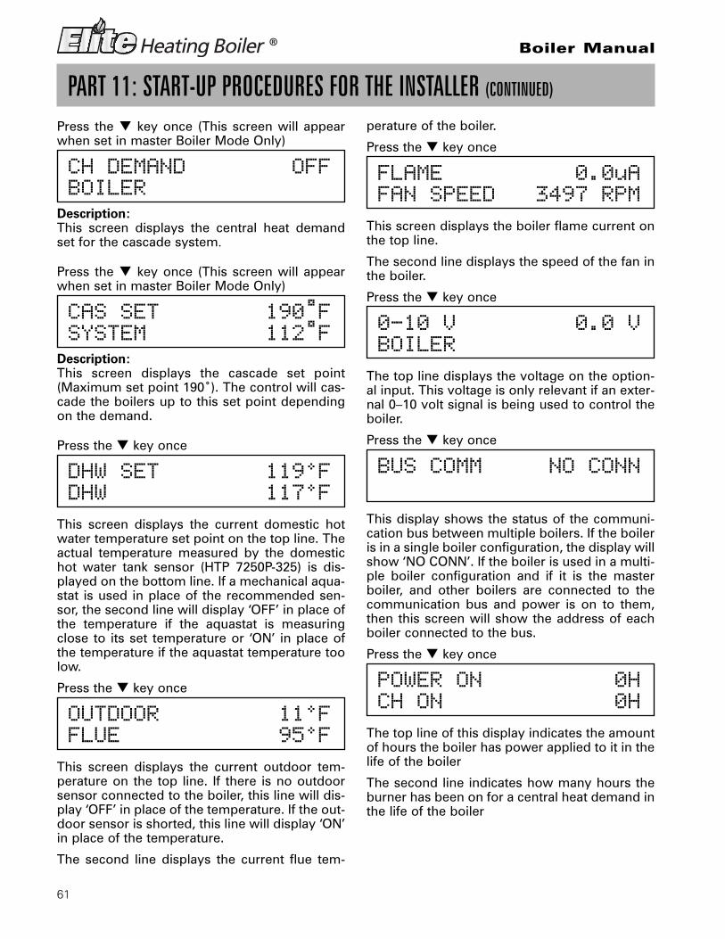
61
Boiler Manual
PART 11: START-UP PROCEDURES FOR THE INSTALLER (CONTINUED)
Press the � key once (This screen will appearwhen set in master Boiler Mode Only)
CH DEMAND OFFBOILER
Description:This screen displays the central heat demandset for the cascade system.
Press the � key once (This screen will appearwhen set in master Boiler Mode Only)
CAS SET 190˚FSYSTEM 112˚F
Description:This screen displays the cascade set point(Maximum set point 190˚). The control will cas-cade the boilers up to this set point dependingon the demand.
Press the � key once
DHW SET 119°FDHW 117°F
This screen displays the current domestic hotwater temperature set point on the top line. Theactual temperature measured by the domestichot water tank sensor (HTP 7250P-325) is dis-played on the bottom line. If a mechanical aqua-stat is used in place of the recommended sen-sor, the second line will display ‘OFF’ in place ofthe temperature if the aquastat is measuringclose to its set temperature or ‘ON’ in place ofthe temperature if the aquastat temperature toolow.
Press the � key once
OUTDOOR 11°FFLUE 95°F
This screen displays the current outdoor tem-perature on the top line. If there is no outdoorsensor connected to the boiler, this line will dis-play ‘OFF’ in place of the temperature. If the out-door sensor is shorted, this line will display ‘ON’in place of the temperature.
The second line displays the current flue tem-
perature of the boiler.
Press the � key once
FLAME 0.0uAFAN SPEED 3497 RPM
This screen displays the boiler flame current onthe top line.
The second line displays the speed of the fan inthe boiler.
Press the � key once
0-10 V 0.0 VBOILER
The top line displays the voltage on the option-al input. This voltage is only relevant if an exter-nal 0–10 volt signal is being used to control theboiler.
Press the � key once
BUS COMM NO CONN
This display shows the status of the communi-cation bus between multiple boilers. If the boileris in a single boiler configuration, the display willshow ‘NO CONN’. If the boiler is used in a multi-ple boiler configuration and if it is the masterboiler, and other boilers are connected to thecommunication bus and power is on to them,then this screen will show the address of eachboiler connected to the bus.
Press the � key once
POWER ON 0HCH ON 0H
The top line of this display indicates the amountof hours the boiler has power applied to it in thelife of the boiler
The second line indicates how many hours theburner has been on for a central heat demand inthe life of the boiler

62
Boiler Manual
PART 11: START-UP PROCEDURES FOR THE INSTALLER (CONTINUED)
Press the � key once
DHW ON 0HGOOD IGNIT 1X
The top line of this display indicates the amountof hours the burner has been on for a domestichot water demand in the life of the boiler. Thesecond line indicates how many times the burn-er has successfully ignited in the life of the boil-er.
The following 10 screens display the last tenlockout faults that the boiler had. The faults aredisplayed from most recent to oldest bydepressing the � key.
Press the � key once (This screen will appearwhen set in master Boiler Mode Only)
SYS CH ON OhSYS DHW ON Oh
Description:This screen displays HOW MANY HOURS RUN-NING FOR THE Central Heat demand and theDHW demand.
FAULT HISTORY 1007/27/2009 Mo 5:19A
This screen displays the last lockout fault theboiler controller had. The top line will alternatebetween the words ‘FAULT HISTORY’ and theactual fault encountered if one has occurred andthe bottom line will display the date and timethat the fault occurred.
Press the � key once
FAULT HISTORY 2008/28/2009 Fr 5:19A
This screen displays the second oldest lockoutfault that occured in the boiler controller. Thetop line will alternate between the words ‘FAULTHISTORY’ and the actual fault encountered ifone has occurred.The bottom line will displaythe date and time that the fault occurred.
Press the � key once
FAULT HISTORY 3008/28/2009 Fr 5:19A
This screen displays the third oldest lockoutfault that occured in the boiler controller. Thetop line will alternate between the words ‘FAULTHISTORY’ and the actual fault encountered ifone has occurred. The bottom line will displaythe date and time that the fault occurred.
Press the � key once
FAULT HISTORY 4008/28/2009 5:19A
This screen displays the fourth oldest lockoutfault that occured in the boiler controller. Thetop line will alternate between the words ‘FAULTHISTORY’ and the actual fault encountered ifone has occurred. The bottom line will displaythe date and time that the fault occurred.
Press the � key once
FAULT HISTORY 5008/28/2009 5:19A
This screen displays the fifth oldest lockout faultthat occured in the boiler controller. The top linewill alternate between the words ‘FAULT HISTO-RY’ and the actual fault encountered if one hasoccurred and the bottom line will display thedate and time that the fault occurred.
Press the � key once
FAULT HISTORY 6008/28/2009 5:19A
This screen displays the sixth oldest lockoutfault that occured in the boiler controller. Thetop line will alternate between the words ‘FAULTHISTORY’ and the actual fault encountered ifone has occurred and the bottom line will dis-play the date and time that the fault occurred.

63
Boiler Manual
PART 11: START-UP PROCEDURES FOR THE INSTALLER (CONTINUED)
Press the � key once
FAULT HISTORY 7008 28 2009 5:19A
This screen displays the seventh oldest lockoutfault that occured in the boiler controller. Thetop line will alternate between the words ‘FAULTHISTORY’ and the actual fault encountered ifone has occurred and the bottom line will dis-play the date and time that the fault occurred.
Press the � key once
FAULT HISTORY 8008 28 2009 5:19A
This screen displays the eighth oldest lockoutfault that occured in the boiler controller. Thetop line will alternate between the words ‘FAULTHISTORY’ and the actual fault encountered ifone has occurred and the bottom line will dis-play the date and time that the fault occurred.
Press the � key once
FAULT HISTORY 9008 28 2009 5:19A
This screen displays the ninth oldest lockoutfault that occured in the boiler controller. Thetop line will alternate between the words ‘FAULTHISTORY’ and the actual fault encountered ifone has occurred and the bottom line will dis-play the date and time that the fault occurred.
Press the � key once
FAULT HISTORY 1008 28 2009 10:01A
This screen displays the tenth oldest lockoutfault that occured in the boiler controller. Thetop line will alternate between the words ‘FAULTHISTORY’ and the actual fault encountered ifone has occurred and the bottom line will dis-play the date and time that the fault occurred.
B. ELITE HEATING BOILER TEST MODE
This Function is intended to simplify the gasadjustment if needed. Listed in Figure 11-3 are the
recommended combustion settings for the gastype selected to run the Elite Heating Boilers.Automatic modulation does not take place whenthe controller is in Test Mode. The boilers will mod-ulate down if the program set point is reachedwhile running in Test Mode. It is recommendedyou open as many heating zones as possible tocreate a heat demand so the test mode operationwill not be interrupted. To exit the Test Mode, Pressthe ‘Up’ and ‘Down’ arrow keys simultaneously.NOTE: The boiler will automatically exit the TestMode after 20 minutes of operation.
C. CASCADE MENU
This menu is accessed by pressing the � keyfrom the default menu or the � key from the sta-tus menu.
CASCADE MASTER READYSYS PUMP OFF
This screen is an informative screen to tell theuser that the boiler is configured as a cascademaster boiler and that the cascade system isready to accept a demand for heat. The secondline indicates the status of the system pump out-put of the cascade system. This screen will alter-nate with the default screen every 5 seconds orit can be accessed by pressing the � key fromthe default screen.
CASCADE NO FOLLOWERSYS PUMP OFF
Description: This screen will be displayed whenthe boiler is configured as a master boiler andthere are no follower boilers connected to themaster or if none of the follower boilers are pow-ered up. The second line indicates the status ofthe system pump output of the cascade system.This screen will alternate with the default screenevery 5 seconds or it can be accessed by pressingthe � key from the default screen.
CASCADE NO SENSORSYS PUMP OFF
Description: This screen will be displayed whenthe boiler is configured as a master boiler andthere is no system temperature sensor connected

64
Boiler Manual
PART 11: START-UP PROCEDURES FOR THE INSTALLER (CONTINUED)
or the system sensor is defective. The cascadesystem will still function in this situation and willfunction with reduced efficiency. All boilers willrun simultaneously rather than in a staged fash-ion. The second line indicates the status of thesystem pump output of the cascade system. Thisscreen will alternate with the default screen every5 seconds or, it can be accessed by pressing the� key from the default screen.
CASCADE TT 0123 567SYS PUMP ON 12:47P
Description: This screen shows information aboutthe cascade status. The TT in the center of the topline shows that the cascade demand is comingfrom the TT contact being closed. You may alsosee DHW if the demand is from a DHW sensor or0-10 if the demand is from a 0-10 volt input. Thefollowing numbers show which boiler addressesare currently communicating to the master. If aboiler address is not used or not communicating,the number will not show on the display. In theexample above, boiler address #4 is not commu-nicating. When a boiler in the system is firing, itsaddress number will alternate with a ‘.’ to signify itis firing. The bottom line shows the status of thesystem pump output contacts.
Press the � key,
CASCADE PWR 100%PRESENT 01234567
Description : This screen shows the overall cas-cade power output. The range of this value isthe number of boilers communicating with themaster x 100 so in the previous screen, the max-imum cascade power is 800%. The second lineshows which boiler addresses are communicat-ing with the master boiler.
Press the � key,
CASCADE SYST 118°FCASCADE SET 190°F
Description: This screen shows the current sys-tem temperature sensor reading on the top lineand the cascade system temperature setting onthe bottom line.
Press the � key,
BOILER 0 100 %BOILER 1 56 %
Description: This screen shows the current cas-cade power output on a per connected boilerbasis for boilers addressed as 0 and 1. In theabove screen, boiler 0 is at 100% firing rate andboiler 1 is at 56% firing rate. If this were a 2 boil-er system, the ‘CASCADE PWR’ screen abovewould now be at 156%
Press the � key,
BOILER 2 0 %BOILER 3 0 %
Description: This screen shows the current cas-cade power output on a per connected boilerbasis. This screen is the same as the one aboveexcept that it shows the power output of boilersaddressed as 2 and 3
Press the � key,
BOILER 4 0 %BOILER 5 0 %
Description: This screen shows the current cas-cade power output on a per connected boilerbasis. This screen is the same as the one aboveexcept that it shows the power output of boilersaddressed as 4 and 5
Press the � key,
BOILER 6 0 %BOILER 7 0 %
Description: This screen shows the current cas-cade power output on a per connected boilerbasis. This screen is the same as the one aboveexcept that it shows the power output of boilersaddressed as 6 and 7.

65
Boiler Manual
PART 12: TROUBLESHOOTINGA. ELITE HEATING BOILER® ERROR CODE
If any of the sensors detect an abnormal condi-tion or an internal component fails during theoperation of the Elite Heating Boiler®, the dis-play may show an error message and errorcode. This message and code may either be theresult of a temporary condition in which casethe display will revert to its normal readoutwhen the condition is corrected or it may be theresult of a condition that the controller has eval-uated as not safe to restart the boiler. In thiscase, the boiler control will be locked out, thered FAULT Light will be lit steadily and the mes-sage “LOCKOUT” will be displayed on the read-out on the lower line. The Elite Heating Boiler®
will not start until a qualified technician hasrepaired the boiler and pressed the RESET but-ton for more than 1 second. If there is an errormessage displayed on the readout and the mes-sage “LOCKOUT” is not displayed and theFAULT light is not lit, then the message is theresult of a temporary condition and will disap-pear when the problem corrects itself. IMPOR-TANT NOTE: If you see error messages on yourdisplay readout, call a technician immediatelysince the message may be indicating that amore serious problem will occur soon.
B. BOILER ERROR
When an error condition occurs, the controllerwill display a description and code on the dis-play readout. These error messages and their
COMBUSTION SETTINGS ON ALL MODELS
Natural Gas Propane LPlow high low high
Carbon Monoxide(CO %) 0–20 ppm 70 ppm–135 ppm 0–20 ppm 80 ppm–150 ppm
Carbon Dioxide(CO2 %) 8½% – 9½% 8½% – 9½% 9½% – 10½% 9½% – 10½%
Fig. 11-3
PART 11: START-UP PROCEDURES FOR THE INSTALLER (CONTINUED)
and ENTER key together for 1 second. The boil-er will go through the ignition sequence then theuser will adjust the Fan Speed by pressing theup arrow key � to increase the fan speed or thedown arrow key � to decrease the fan speed.
To leave Service Mode, press the up � anddown � arrow keys simultaneously.
SERVICE RUN 3400 RPMPUMP ON 4:49P
D. TEST MODE ACCESS
To Activate the test mode Press the up arrow �
recommended corrective actions are describedin section D. USER INTERFACE DISPLAY.
C. BOILER FAULT
1. When a fault condition occurs, the controllerwill illuminate the red “FAULT” indication lightand display a fault message in the screen.The alarm output will also be activated. Mostfault conditions will also cause the CH pumpto run in an attempt to cool the boiler.
2. Note the fault message that is displayed andrefer to Part D in this section for anexplanation of the fault message along withseveral suggestions for corrective actions.
3. Press the reset key to clear the fault andresume operation. Be sure to observe theoperation of the unit for a period of time toassure correct operation and no re-occurrence of fault message.
n WARNINGWhen servicing or replacing any components of thisboiler be certain that:• The gas is off.• All electrical power is disconnected

66
Boiler Manual
PART 12: TROUBLESHOOTING (CONTINUED)
D. USER INTERFACE DISPLAYCascade Control FAULT CodesFault Code EO3System Sensor Failure
SYS SUPPLY SENSORPUMP OFF E03
Description:This screen shows that there is a problem withthe system sensor circuit. The circuit could beeither open or shorted. Possible reasons for thiserror to be present are:• There is no system sensor connected to the
master boiler• The system sensor is faulty• There is a short circuit in the system sensor
wiring; possibly from a staple placedthrough the wire or damage to the wire
causing both conductors to touch.• The system sensor wiring is open due to
defect or damage. Remedy:Disconnect the system sensor from the wiring andmeasure the resistance of it. Compare the meas-ured resistance to the table in this manual to seeif it corresponds to the temperature of the sensor.If the resistance does not agree with the tempera-ture of the sensor, replace the sensor. If the sensoris OK, disconnect the sensor wiring from both theboiler and the sensor and check continuity usingan ohmmeter. Repair or replace as necessary.
If this error is present, all boilers in the cascadedgroup will run and ignite simultaneously whenthere is a heat demand. Each boiler will modulateto maintain set point temperature on its own sup-ply sensor. The code will reset automatically whenrepair is complete. This code will not display ifSystem Setting Function ERROR SYSTEM SENSis set to OFF.
Fault Code TTTemperature Blocking TT demand
TEMPER BLOCKINGPUMP ON TT
Description:This screen shows that there is a demand on theboiler from the TT circuit and that the pump ispowered on and the temperature of the water atthe supply sensor is too high for the boiler toignite. This occurs because the water tempera-ture measured by the supply sensor is higherthan the central heat setting – Central DiffSetting, when a demand from the TT circuit isplaced on the boiler. This message will staypresent until the water temperature measuredby the supply sensor is less than the CentralHeat Setting – Central Diff Setting.
Fault Code DHWTemperature blocking DHW demand
TEMPER BLOCKINGPUMP ON DHW
Description:This screen shows that there is a demand on theboiler from the DHW circuit and the pump is
n CAUTIONThis appliance has wire function labels on all internalwiring. Observe the position of each wire before re-moving it. Wiring errors may cause improper and dan-gerous operation. Verify proper operation after servicing.
n CAUTIONIf overheating occurs or the gas supply fails to shutoff, do not turn off electrical power to the circulatingpump. This may aggravate the problem and increasethe likelihood of boiler damage. Instead, shut off thegas supply to the boiler at the gas service valve.
n WARNINGDo not use this appliance if any part has been underwater. Improper or dangerous operation may result.Contact a qualified service technician to inspect theboiler and to repair or replace any part of the boilerthat has been under water prior to placing the boilerback in operation.
n DANGERWhen servicing or replacing components that are indirect contact with the boiler water, be certain that:• There is no pressure in the boiler. (Pull the releaseon the relief valve. Do not depend on the pressuregauge reading).• The boiler water is not hot• The electrical power is off
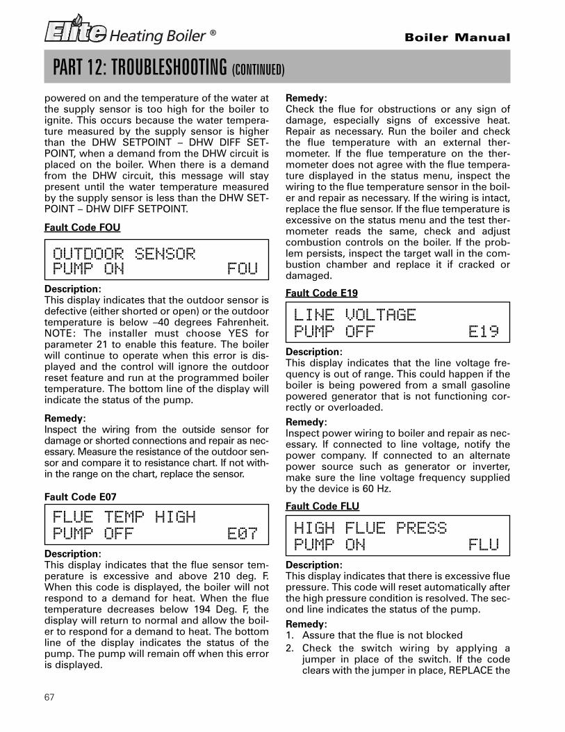
67
Boiler Manual
PART 12: TROUBLESHOOTING (CONTINUED)
powered on and the temperature of the water atthe supply sensor is too high for the boiler toignite. This occurs because the water tempera-ture measured by the supply sensor is higherthan the DHW SETPOINT – DHW DIFF SET-POINT, when a demand from the DHW circuit isplaced on the boiler. When there is a demandfrom the DHW circuit, this message will staypresent until the water temperature measuredby the supply sensor is less than the DHW SET-POINT – DHW DIFF SETPOINT.
Fault Code FOU
OUTDOOR SENSORPUMP ON FOU
Description:This display indicates that the outdoor sensor isdefective (either shorted or open) or the outdoortemperature is below –40 degrees Fahrenheit.NOTE: The installer must choose YES forparameter 21 to enable this feature. The boilerwill continue to operate when this error is dis-played and the control will ignore the outdoorreset feature and run at the programmed boilertemperature. The bottom line of the display willindicate the status of the pump.
Remedy:Inspect the wiring from the outside sensor fordamage or shorted connections and repair as nec-essary. Measure the resistance of the outdoor sen-sor and compare it to resistance chart. If not with-in the range on the chart, replace the sensor.
Fault Code E07
FLUE TEMP HIGHPUMP OFF E07
Description:This display indicates that the flue sensor tem-perature is excessive and above 210 deg. F.When this code is displayed, the boiler will notrespond to a demand for heat. When the fluetemperature decreases below 194 Deg. F, thedisplay will return to normal and allow the boil-er to respond for a demand to heat. The bottomline of the display indicates the status of thepump. The pump will remain off when this erroris displayed.
Remedy:Check the flue for obstructions or any sign ofdamage, especially signs of excessive heat.Repair as necessary. Run the boiler and checkthe flue temperature with an external ther-mometer. If the flue temperature on the ther-mometer does not agree with the flue tempera-ture displayed in the status menu, inspect thewiring to the flue temperature sensor in the boil-er and repair as necessary. If the wiring is intact,replace the flue sensor. If the flue temperature isexcessive on the status menu and the test ther-mometer reads the same, check and adjustcombustion controls on the boiler. If the prob-lem persists, inspect the target wall in the com-bustion chamber and replace it if cracked ordamaged.
Fault Code E19
LINE VOLTAGEPUMP OFF E19
Description:This display indicates that the line voltage fre-quency is out of range. This could happen if theboiler is being powered from a small gasolinepowered generator that is not functioning cor-rectly or overloaded.Remedy:Inspect power wiring to boiler and repair as nec-essary. If connected to line voltage, notify thepower company. If connected to an alternatepower source such as generator or inverter,make sure the line voltage frequency suppliedby the device is 60 Hz.
Fault Code FLU
HIGH FLUE PRESSPUMP ON FLU
Description:This display indicates that there is excessive fluepressure. This code will reset automatically afterthe high pressure condition is resolved. The sec-ond line indicates the status of the pump.Remedy:1. Assure that the flue is not blocked2. Check the switch wiring by applying a
jumper in place of the switch. If the codeclears with the jumper in place, REPLACE the

68
Boiler Manual
PART 12: TROUBLESHOOTING (CONTINUED)
flue switch and connect the wires to the newswitch BEFORE running unit.WARNING: Do not use jumper to remedythis error. Faulty switch MUST be replaced.Failure to do so could result in serious injuryor death.
Fault Code PRO
LOW WATER PRESSPUMP OFF PRO
Description:This display indicates that there is low water pres-sure in the boiler. This code will reset automatical-ly after the water pressure is high enough for theboiler to run safely. The second line indicates thestatus of the pump. Note that while the waterpressure is low, the pump will be off.Remedy:1. Assure that the system pressure is above 10
psig.2. Check for leaks in the system piping.Fault Code LOU
24 VOLT LOWPUMP ON LOU
Description:This display indicates that the 24 volt powersupply on the control is damaged or over-loaded. This code will reset automatically if it isthe result of an overload and that overload con-dition is removed. The second line indicates thestatus of the pump. Note that while 24 voltpower is low, the pump output will be on.Remedy:1. Check line voltage. It must be between 100-
128 volts.2. If available, connect PC and using HTP serv-
ice software check the 24v supply display inthe lower left corner of the screen. The num-ber displayed here must be greater than 128and should be no greater than 250. Use thisas a troubleshooting guide as you follow thesteps below.
3. Remove the 10 pin Molex Connector fromcustomer connection board. If the messageclears, then the problem is with the external
sensor wiring. Examine the external sensorwiring for shorts to the ground, repairing asnecessary. If the message is still present andthe boiler is so equipped, disconnect the UL353 low water cut-off to see if the messageclears. Replace the faulty part. Check the lowvoltage wire harness in boiler for shorts toground.
4. If a message only occurs when the burnertries to light, check the gas valve for exces-sive current draw.
5. If a message is present with the low voltageharness disconnected from the 926 controlboard, replace the 926 control board.
Fault Code FL
LOW WATER FLOW FLPUMP OFF
Description:This display indicates that there is low water flowin the boiler. This code should never be displayedon the Elite Heating Boiler® since there is no flowswitch in this product. This code will display onVWH products only. This code will reset automat-ically when the water flow is high enough for theboiler to run safely. The second line indicates thestatus of the pump. The pump should always beon when this code is displayed. When there is ademand, the control will start the pump, wait forthe flow switch to indicate flow then try to ignitethe boiler. This display occurs after the pump isenergized for several seconds and the flow is stilltoo low.Remedy:1. Check to see if boiler pump is functioning.
Repair as necessary.2. Be sure water is flowing in the system.
Check for valves that should be open,plugged filter screens, etc.
3. Check the flow switch and wiring. Repair asnecessary.

69
Boiler Manual
PART 12: TROUBLESHOOTING (CONTINUED)
Fault Code F00
WATER HIGH TEMP F00PUMP ON
Description:This display indicates if the water in the boiler hasoverheated. This code indicates a serious safetyissue and the boiler will not restart until it coolsdown sufficiently and a technician repairs thecause of the overheating and pushes the RESETbutton on the display. This is a serious situationand is indicated by the red light on the displayilluminating and the word LOCKOUT flashing onthe display. During this lockout fault, the pumpwill be on as indicated on the second line of thedisplay in an effort to cool the boiler down.Remedy:1. Check circulator pump operation2. If the circulator pump is running, be sure that
there is water in the system and that the wateris moving through the system as intended. Besure that all correct ball valves and or zonevalves are open or closed as intended.
3. Observe the temperature/pressure gauge. Ifthe water is not too hot and this message isdisplayed, check the wiring to the water ECOsensor and repair if necessary. If the wiring isok and this code is still present and the wateris not excessively hot, replace the ECO sensor.
Fault Code F01
FLUE TEMP/WAT LVPUMP ON F01
Description:This display indicates that the flue temperaturelimit switch of the boiler has tripped or that thewater level in the boiler is low (The will onlyoccur if the optional UL353 LWCO is installed).This code indicates a serious safety issue. Theboiler will not restart until the flue cools downsufficiently or the water level is restored. A tech-nician must repair the cause of the problem andpush the RESET button on both the low watercut-off control box and the display. This situa-tion is indicated by the red light on the displayand the word LOCKOUT flashing on the display.During this lockout fault, the pump will be on asindicated on the second line of the display.Remedy:
1. If the boiler has a UL353 LWCO, check to seeif the red LED on the LWCO control box isilluminated. If so, correct the low water con-dition and press the reset button on theLWCO control box to reset the LWCO. TheLED should change to green. Press the resetbutton on the front panel of the boiler toreset the boiler control.
2. Check the flue for obstructions or any sign ofdamage especially signs of excessive heat.Repair as necessary. Push the red reset but-ton on flue temperature switch located onthe flue inside the rear access door of theboiler. NOTE: The switch temperature mustbe less than 90°F to reset. Press the resetbutton on the display. Run the boiler andcheck the flue temperature by using both anexternal thermometer in the flue pipe andthe flue temperature display in the statusscreens. If the flue temperature is withinspecs and the switch trips, replace theswitch. If the flue temperature is excessive,check and adjust combustion controls on theboiler. If the problem persists, inspect thetarget wall in the combustion chamber andreplace it if cracked or damaged.
Fault Code F02
SUPPLY SENSORPUMP ON F02
Description:This display indicates that the supply tempera-ture sensor of the boiler has failed. This codeindicates a serious safety issue and the boilerwill not restart until the sensor is replaced by atechnician and he pushes the RESET button onthe display. This situation is indicated by the redlight on the display and the word LOCKOUTflashing on the display. During this lockout fault,the pump will be on as indicated on the secondline of the display.Remedy:1. Check the electrical connection to the ther-
mistor on the outlet manifold. Verify 5 VDCby checking in Molex Connector. If there isno 5 VDC, check the harness. If harness isOK, replace control. NOTE: The boiler willreset automatically. Verify thermistor valuesby referencing chart in this manual.
2. Replace thermistor if necessary.
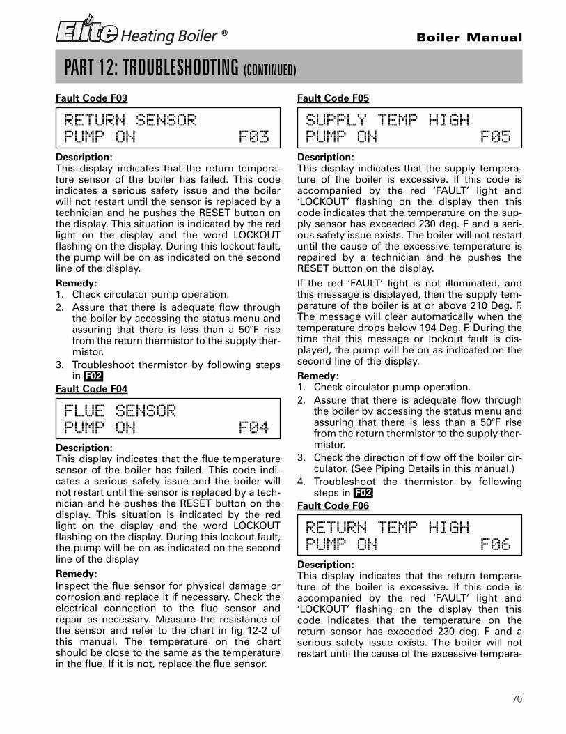
70
Boiler Manual
PART 12: TROUBLESHOOTING (CONTINUED)
Fault Code F03
RETURN SENSORPUMP ON F03
Description:This display indicates that the return tempera-ture sensor of the boiler has failed. This codeindicates a serious safety issue and the boilerwill not restart until the sensor is replaced by atechnician and he pushes the RESET button onthe display. This situation is indicated by the redlight on the display and the word LOCKOUTflashing on the display. During this lockout fault,the pump will be on as indicated on the secondline of the display.Remedy:1. Check circulator pump operation.2. Assure that there is adequate flow through
the boiler by accessing the status menu andassuring that there is less than a 50°F risefrom the return thermistor to the supply ther-mistor.
3. Troubleshoot thermistor by following stepsin |F02|
Fault Code F04
FLUE SENSORPUMP ON F04
Description:This display indicates that the flue temperaturesensor of the boiler has failed. This code indi-cates a serious safety issue and the boiler willnot restart until the sensor is replaced by a tech-nician and he pushes the RESET button on thedisplay. This situation is indicated by the redlight on the display and the word LOCKOUTflashing on the display. During this lockout fault,the pump will be on as indicated on the secondline of the displayRemedy:Inspect the flue sensor for physical damage orcorrosion and replace it if necessary. Check theelectrical connection to the flue sensor andrepair as necessary. Measure the resistance ofthe sensor and refer to the chart in fig 12-2 ofthis manual. The temperature on the chartshould be close to the same as the temperaturein the flue. If it is not, replace the flue sensor.
Fault Code F05
SUPPLY TEMP HIGHPUMP ON F05
Description:This display indicates that the supply tempera-ture of the boiler is excessive. If this code isaccompanied by the red ‘FAULT’ light and‘LOCKOUT’ flashing on the display then thiscode indicates that the temperature on the sup-ply sensor has exceeded 230 deg. F and a seri-ous safety issue exists. The boiler will not restartuntil the cause of the excessive temperature isrepaired by a technician and he pushes theRESET button on the display.If the red ‘FAULT’ light is not illuminated, andthis message is displayed, then the supply tem-perature of the boiler is at or above 210 Deg. F.The message will clear automatically when thetemperature drops below 194 Deg. F. During thetime that this message or lockout fault is dis-played, the pump will be on as indicated on thesecond line of the display.Remedy:1. Check circulator pump operation.2. Assure that there is adequate flow through
the boiler by accessing the status menu andassuring that there is less than a 50°F risefrom the return thermistor to the supply ther-mistor.
3. Check the direction of flow off the boiler cir-culator. (See Piping Details in this manual.)
4. Troubleshoot the thermistor by followingsteps in |F02|
Fault Code F06
RETURN TEMP HIGHPUMP ON F06
Description:This display indicates that the return tempera-ture of the boiler is excessive. If this code isaccompanied by the red ‘FAULT’ light and‘LOCKOUT’ flashing on the display then thiscode indicates that the temperature on thereturn sensor has exceeded 230 deg. F and aserious safety issue exists. The boiler will notrestart until the cause of the excessive tempera-

71
Boiler Manual
PART 12: TROUBLESHOOTING (CONTINUED)
ture is repaired by a technician and he pushesthe RESET button on the display.If the red ‘FAULT’ light is not illuminated, andthis message is displayed, then the return tem-perature of the boiler is at or above 210 Deg. F.The message will clear automatically when thetemperature drops below 194 Deg. F. During thetime that this message or lockout fault is dis-played, the pump will be on as indicated on thesecond line of the display.Remedy:1. Check circulator pump operation.2. Assure that there is adequate flow through the
boiler by accessing the status menu and assur-ing that there is less than a 50°F rise from thereturn thermistor to the supply thermistor.
3. Check the direction of flow on boiler circulator.(See Piping Details in Section 5 of this manual.)
4. Troubleshoot thermistor by following steps in|F02|
Fault Code F09
NO FLAME ON IGNPUMP ON F09
Description:The boiler tried to ignite four times during oneheat call and failed ignition all four times. Thered light will display and the word LOCKOUT willflash on the display. This code indicates a seri-ous safety issue and the boiler will not restartuntil the cause of no ignition is repaired by atechnician and he pushes the RESET button onthe display. During this lockout fault, the pumpwill remain on as indicated on the second line ofthe displayRemedy:1. Watch the igniter through the observation
window provided.2. If there is no spark, check the spark electrode
for the proper .196” (5.0 mm ± 1mm) gap. 3. Remove any corrosion from the spark elec-
trode and flame rectifier probe.4. If there is a spark but no flame, check the gas
supply to the boiler.5. If there is a flame, check the flame sensor.6. Check any flue blockage or condensate
blocks.
Fault Code F10
FLAME LOSSF10
Description:The flame was lost while the boiler was firing 3times during 1 demand call. The red light willdisplay and the word LOCKOUT will flash on thedisplay. This code indicates a serious safetyissue and the boiler will not restart until thecause of the flame loss is determined by a tech-nician and he pushes the RESET button on thedisplay. During this lockout fault, the pump willbe on as indicated on the second line of the dis-play.Remedy:1. Monitor the gas pressure to the unit while in
operation.2. Assure that the flame is stable when lit.3. Check to see if the display readout changes
from “GAS VALVE ON” to “RUN” within afew seconds after the boiler ignites
4. Check the FLAME signal on the status dis-play. It should be above 1.0 when the boileris firing.
5. If the signal reads less than 1 microampere,clean the flame rectifier and spark probe.
6. If the problem persists and the ‘FLAME” sig-nal is still less than 1.0, replace the flameprobe and spark igniter probe.
7. The flame signal should be steady after theboiler has been firing for 1 minute and is nor-
4.5mm
Elite Spark Electrode Gap Spacing
Top View
.177 "
Fig. 12-1 NOTE: If receiving an F09 fault code,check the gap spacing between points onthe electrode.
5.0 mm ± 1mm.196" ± .039

72
Boiler Manual
PART 12: TROUBLESHOOTING (CONTINUED)
mally at 5.0 to 9.0. If the flame signal is notsteady, disassemble the burner door andcheck the burner and its sealing gaskets.
Fault Code F11
FALSE FLAME SIGPUMP ON F11
Description:There is flame when the boiler control is nottelling the boiler to run. The red light will displayand the word LOCKOUT will flash on the display.This code indicates a serious safety issue andthe boiler will not restart until the cause is deter-mined by a technician and he pushes the RESETbutton on the display. During this lockout fault,the pump will be on as indicated on the secondline of the display.Remedy:1. Look into window. If there is flame, turn the
gas off to the unit at the service valve andreplace the gas valve.
2. If the flame signal on the status menu isgreater than 1.0 when the burner is not lit,replace the spark ignitor and the flame recti-fication probe.
3. If the flame signal is not present after turningoff the gas supply, check the gas valve elec-trical connection.
4. Check for condensate backup. Repair con-densate system as necessary. If condensatehas partially filled the combustion chamber,the refractory wall may be damaged andshould be replaced.
5. Turn the gas on at the service valve after cor-rective action is taken.
6. If the refractory wall falls against the rectifierprobe, it may conduct the signal to ground,giving a false reading.
Fault Code F13
FAN SPEED ERRORPUMP ON F13
Description:The fan is not running at the speed that the con-trol has commanded it to run at. The fan speedhad been more than 30% faster or slower thanthe commanded speed for more than 10 sec-onds. The red light will display and the word
LOCKOUT will flash on the display. This codeindicates a serious safety issue and the boilerwill not restart until the cause is determined bya technician and he pushes the RESET button onthe display. During this lockout fault, the pumpwill be on as indicated on the second line of thedisplay.Remedy:1. Check the combustion air fan wiring.2. Measure the DC voltage from the red fan
wire to ground while it is connected to thefan. It should be between 24 to 40 volts. If itis lower than 24 volts, check for excessiveexternal loads connected to the boiler sen-sor terminals. Disconnect the 5 pin plug fromthe fan and check the voltage on the red wireagain. If it is now between 24-40 volts,replace the fan. If it is still below 24 voltsreplace the boiler control board.
Fault Code F20
CONDENSATE FULLPUMP ON F20
Description:The condensate trap is full of condensate. Thered light will display and the word LOCKOUT willflash on the display. This code indicates a seri-ous safety issue and the boiler will not restartuntil the cause is determined by a technicianand he pushes the RESET button on the display.During this lockout fault, the pump will be off asindicated on the second line of the display.Remedy:1. Check condensate lines for obstructions2. Check float switch in condensate reservoir.3. Check wiring from condensate reservoir to
926 control and repair as necessaryFault Code F31
PROGRAM ERRORF31
Description:There was an error while programming the con-trol and the control’s memory is corrupt. Theboiler control will not function in this state andthe pump will be off as indicated on the bottomline of the display. The only way for this error tooccur is if a technician is programming the con-

Outdoor Sensor (7250P-319)
Outside Temperature (°F) Resistance (ohms)
–22 171800
–13 129800
–4 98930
5 76020
14 58880
23 45950
32 36130
41 28600
50 22800
59 18300
68 14770
77 12000
86 9804
95 8054
104 6652
113 5522
Water Temperature (°F) Resistance (ohms)
32 32550
41 25340
50 19870
59 15700
68 12490
77 10000
86 8059
95 6535
104 5330
113 4372
122 3605
131 2989
140 2490
149 2084
158 1753
167 1481
176 1256
185 1070
194 915
203 786
212 667
Supply Temperature Sensor 7250P-324
Boiler Sensor (7250P-667) Indirect Sensor (72 50P-325)
Resistance Tables
Fig. 12-2
73
Boiler Manual
trol and the programming function fails. Theonly way to recover from this error is to pro-gram the control again. If this error occurs at anytime other than when a technician is servicingthe boiler, the control has failed and must bereplaced by a qualified technician.Remedy:The control must be re-programmed. If pro-gramming does not solve problem, the controlmust be replaced.
Fault Code PP
CONTROL PROGRAMEDPP
Description:The control has been programmed by a techni-cian or the factory. After programming, the con-trol is left in a locked out mode. Press the‘RESET’ key to begin use of the control.Remedy:Press S4 reset for at least 1 second.
PART 12: TROUBLESHOOTING (CONTINUED)

74
Boiler Manual
PART 13: MAINTENANCEB. COMBUSTION CHAMBER COIL
CLEANING INSTRUCTIONS FORELITE HEATING BOILER®
*Before beginning this procedure, you must have onhand the following items:– a nylon, stainless steel or brass brush (not
steel)– “Rydlyme” (recommended for best
r e s u l t s ) ( a v a i l a b l e o n l i n ewww.rydlyme.com) or “CLR” (available atmost hardware stores)
– Gloves, eye protection1. Shut down the Elite Heating Boiler® by using the
following steps:a. Close the gas valve, shut down the unit
and wait for the unit to be cool to thetouch
b. Disconnect the condensate piping fromthe outside connection, (not from theElite Heating Boiler® side), so the flowfrom condensate reservoir can beobserved.
c. Disconnect electrical connections fromthe gas valve, spark electrode and flamerectification probe and combustion blow-er.
d. Remove the (4) screws on the aluminum¾” NPT connector on the right side of thegas valve.
e. Disconnect the wiring connected to thecombustion blower motor.
f. Remove the (6) 10MM nuts from theburner plate assembly.
g. Pull the entire burner plate assembly withblower still attached towards you, whileremoving or pushing aside any wiring toallow the removal of the assembly.
2. Using a spray bottle filled with the recommend-ed product “RYDLYME” or “CLR”, spray liberallyon the coils, making sure the solution penetratesand funnels down through the condensate sys-tem. If the condensate system is blocked, let thechemical penetrate for at least 15 minutes oruntil it drains.
3. Use the nylon, stainless steel or brass brush (donot use steel) and scrub coils to remove anybuildup, then vacuum the debris from the coils.
4. Spray the coils with clear water, making sure toconfine the spray to the area being cleaned (Tryto avoid getting the back ceramic wall of the unitwet). Flush the combustion chamber with fresh
A. MAINTENANCE PROCEDURES
Periodic maintenance should be performedonce a year by a qualified service technician toassure that all the equipment is operating safelyand efficiently. The owner should make neces-sary arrangements with a qualified heating con-tractor for periodic maintenance of the heater.The installer must also inform the owner that thelack of proper care and maintenance of theheater may result in a hazardous condition.
n WARNINGThe combustion chamber insulation inthis product contains ceramic fibermaterial. Ceramic fibers can beconverted to cristobalite in very hightemperature app l i ca t ions . TheInternational Agency for Research onCancer ( IARC) has conc luded ,“Crystalline silica inhaled in the form ofquartz or cristobalite from occupationalsources is carcinogenic to humans(Group1).”:� Avoid breathing dust and contact with skin and
eyes.• Use NIOSH certified dust respirator (N95). This
type of respirator is based on the OSHArequirements for cristobalite at the time thisdocument was written. Other types of respiratorsmay be needed depending on the job siteconditions. Current NIOSH recommendationscan be found on the NIOSH website athttp://www.cdc.gov/niosh/homepage.html.NIOSH approved respirators, manufacturers, andphone numbers are also listed on this website.
• Wear long-sleeved, loose fitting clothing,gloves, and eye protection.
� Apply enough water to the combustion chamberlining to prevent dust
� Wash potentially contaminated clothes separatelyfrom other clothing. Rinse clothes washerthoroughly.
NIOSH stated First Aid.� Eye: Irrigate immediately� Breathing: Fresh air.
n WARNINGBEFORE EACH HEATING SEASON A trained andqualified service technician should perform theinspections as per the boiler inspection andmaintenance schedule in the back of manual. Failureto do so could result in death or serious injury.

75
Boiler Manual
water until clear water runs from the conden-sate. At this point, the boiler should be ready tobe re-assembled.a. Inspect gaskets.b. Re-install the burner assemblyc. Replace and tighten the (6) 10MM nuts to
the burner plate using staggered tighten-ing sequence. (See detail)
d. Re-connect all wiring connections
e. Inspect the gas valve to assure the O-ringis in place. Replace the (4) screws on thealuminum connector on the gas valve.Turn the gas back on. (IMPORTANT:CHECK FOR GAS LEAKS)
g. Turn the Elite Heating Boiler® power backon and create a demand on the boiler.When boiler is lit, observe condensateflow from the boiler. Be sure the boiler isoperating properly.
h. Re-connect the condensate piping to theoutside condensate connection.
PART 13: MAINTENANCE (CONTINUED)

76
Boiler Manual
PART 13: MAINTENANCE (CONTINUED)
Fig. 13-1
32
35
34
36
1
234
5
6
7
89
10
11
12
13
14
15
24
16
21
23
25
27
26
28
17
18
20
22
19
37
29
3033
31
38
ITEM # EL-80 EL-110 EL-150 EL-220 Description
1 7450P-001 7450P-002 7450P-003 7450P-004 BOILER MODULE
2 7250P-160 7250P-160 7250P-160 7250P-160 CERAMIC TARGET WALL
3 7500P-109 7500P-109 7500P-109 7500P-109 M4 FLAT WASHER
4 7250P-704 7250P-704 7250P-704 7250P-704 M4 X 8 FLAT HEAD SCREW
5 7450P-006 7450P-006 7450P-006 7450P-006 BURNER DOOR
6 7450P-005 7450P-005 7450P-005 7450P-005 BURNER DOOR INSULATION
7 7450P-009 7450P-010 7450P-011 7450P-012 BURNER
8 7500P-074 7500P-074 7500P-074 7500P-074 GASKET - BURNER
9 7450P-008 7450P-008 7450P-007 7450P-007 AIR CHANNEL
10 7250P-206 7250P-206 7250P-206 7250P-206 M5 X 14MM TORX SCREWS - AIR CHANNEL
11 7500P-075 7500P-075 7500P-075 7500P-075 GASKET - AIR CHANNEL/BLOWER
12 7500P-031 7500P-031 7500P-031 7350P-159 COMBUSTION BLOWER
13 7250P-478 7250P-478 7250P-478 7250P-478 M5 X 12MM SOCKET CAP SCREW
14 7450P-022 7450P-023 7450P-024 7450P-024 AIR/GAS MIXER
15 7450P-141 7450P-141 7450P-141 7450P-225 SCREWS - AIR/GAS MIXER
16 7450P-115 7450P-115 7450P-115 7450P-115 WASHER - AIR/GAS MIXER
17 7450P-139 7450P-139 7450P-139 7450P-138 FLARE X BSP FITTING
18 7100P-140 7100P-140 7100P-140 7450P-140 FLEXIBLE GAS LINE
19 7450P-025 7450P-025 7450P-025 7350P-033 GAS VALVE
20 7450P-154 7450P-154 7450P-154 7450P-143 FLARE X NPT FITTING
21 7500P-067 7500P-067 7500P-067 7500P-067 M6 NUT - BURNER DOOR
22 7250P-005 7250P-005 7250P-005 7250P-005 GASKET - PROBE/ELECTRODE
23 7350P-020 7350P-020 7350P-020 7350P-020 SPARK ELECTRODE (W/GASKET)
24 7250P-069 7250P-069 7250P-069 7250P-069 SCREW M4 X 8MM - PROBE/ELECTRODE
25 7350P-022 7350P-022 7350P-022 7350P-022 FLAME RECTIFICATION PROBE (W/GASKET)
26 7250P-667 7250P-667 7250P-667 7250P-667 THERMISTOR
27 7250P-096 7250P-096 7250P-096 7250P-096 WATER PRESSURE SWITCH - NPT THREAD
28 7450P-192 7450P-192 7450P-192 7450P-192 THERMISTOR/WATER TEMP SWITCH
29 7450P-185 7450P-185 7500P-057 7500P-057 CONDENSATE HOSE
30 7450P-200 7450P-200 7450P-200 7450P-200 CONDENSATE COLLECTOR ASSY
31 7250P-210 7250P-210 7250P-210 7250P-210 HOSE CLAMP
32 7450P-144 7450P-144 7450P-144 7450P-147 PAN HEAD SCREW
33 7350P-063 7350P-063 7350P-063 7350P-063 #10 X 1/2" SELF TAPPING SCREW - CONDENSATE
34 7450P-199 7450P-199 7450P-199 7450P-199 1/4" NPT NIPPLE
35 7450P-220 7450P-220 7450P-220 7450P-220 AIR/GAS MIXER INLET ASSY
36 7450P-197 7450P-197 7450P-197 7450P-197 AIR RELEASE VENT
37 7350P-167 7350P-167 7350P-167 7350P-167 CONDENSATE OVERFLOW SWITCH
38 7450P-165 7450P-165 7450P-165 7450P-165 SET SCREW - 10-32 X 3/8
LP-293-CREV. 1/19/10

77
Boiler Manual
PART 13: MAINTENANCE (CONTINUED)
Fig. 13-2
ITEM # EL-299 EL-399 Description
1 7450P-014 7450P-015 BOILER MODULE
2 7250P-160 7250P-160 CERAMIC TARGET WALL
3 7500P-109 7500P-109 M4 FLAT WASHER
4 7250P-704 7250P-704 M4 X 8 FLAT HEAD SCREW
5 7450P-006 7450P-006 BURNER DOOR
6 7450P-005 7450P-005 BURNER DOOR INSULATION
7 7350P-031 7350P-031 BURNER
8 7500P-074 7500P-074 GASKET - BURNER
9 7450P-007 7450P-007 AIR CHANNEL
10 7250P-206 7250P-206 M5 X 14MM TORX SCREWS - AIR CHANNEL
11 7500P-075 7500P-075 GASKET - AIR CHANNEL/BLOWER
12 7350P-159 7350P-159 COMBUSTION BLOWER
13 7250P-478 7250P-478 M5 X 12MM SOCKET CAP SCREW
14 7450P-029 7450P-029 AIR/GAS MIXER
15 7450P-225 7450P-225 M4 X 12MM SOCKET BUTTON HEAD SCREW
16 7500P-067 7500P-067 M6 NUT - BURNER DOOR
17 7450P-115 7450P-115 WASHER - AIR/GAS MIXER
18 7250P-005 7250P-005 GASKET - PROBE/ELECTRODE
19 7350P-020 7350P-020 SPARK ELECTRODE (w/GASKET)
20 7250P-069 7250P-069 SCREW M4 X 8MM - PROBE/ELECTRODE
21 7350P-022 7350P-022 FLAME RECTIFICATION PROBE (w/GASKET)
22 7450P-192 7450P-192 THERMISTOR/WATER TEMP SWITCH
23 7250P-096 7250P-096 WATER PRESSURE SWITCH - NPT THREAD
24 7250P-667 7250P-667 THERMISTOR
25 7350P-033 7350P-033 GAS VALVE
26 7450P-147 7450P-147 M5 X 8MM PAN HEAD SCREW
27 7450P-200 7450P-200 CONDENSATE COLLECTOR ASSY
28 7350P-167 7350P-167 CONDENSATE OVERFLOW SWITCH
29 7350P-063 7350P-063 #10 x 1/2" SELF TAPPING SCREW
30 7250P-210 7250P-210 HOSE CLAMP
31 7450P-140 7450P-140 FLEXIBLE GAS LINE
32 7450P-138 7450P-138 FLARE X BSP FITTING
33 7450P-143 7450P-143 FLARE X NPT FITTING
34 7500P-057 7500P-057 CONDENSATE HOSE
22
24 23
31
32
33
2
1
34
5 6
7
89
10
11
12
13
1420
16
17
19
21
2526
18
27
29 28
34
30
15
LP-293-NREV. 1/18/10

78
Boiler Manual
ITEM # EL-80 EL-110 EL-150 EL-220 EL-299 EL-399 DESCRIPTIOIN
1 7450P-039 7450P-039 7450P-039 7450P-039 7450P-065 7450P-065 JACKET - REAR
2 7450P-055 7450P-055 7450P-056 7450P-038 7450P-064 7450P-068 JACKET - BOTTOM
3 7450P-121 7450P-121 7450P-121 7450P-121 7450P-121 7450P-121 LEVELING FEET
4 7450P-057 7450P-059 7450P-060 7450P-036 7450P-061 7450P-066 JACKET - LEFT SIDE
5 7450P-058 7450P-123 7450P-062 7450P-037 7450P-063 7450P-067 JACKET - RIGHT SIDE
6 7450P-080 7450P-080 7450P-080 7450P-080 7450P-080 7450P-080 10-32 X 5/16 PAN HEAD SCREW - JACKET
7 7450P-081 7450P-081 7450P-081 7450P-081 7450P-081 7450P-081 6-32 X 1/4 PAN HEAD SCREW - ACCESSORIES
8 7450P-074 7450P-074 7450P-074 7450P-074 7450P-075 7450P-075 AIR/EXHAUST SUPPORT PLATE
9 7500P-115 7500P-115 7500P-115 7500P-115 7500P-115 7500P-115 6-32 X 1/4 PAN HEAD SCREW - ELECTRONIC BOARDS
10 7450P-178 7450P-178 7450P-178 7450P-178 N/A N/A FIELD CONNECTION BOARD PLATE
11 7450P-088 7450P-088 7450P-088 7450P-088 7450P-088 7450P-088 8-32 FLANGED NUT - AIR EXHAUST PLATE
12 7450P-030 7450P-030 7450P-030 7450P-030 7450P-031 7450P-031 AIR INLET ADAPTER
13 7450P-032 7450P-032 7450P-032 7450P-032 7450P-033 7450P-033 AIR INLET CONNECTOR NUT
14 7450P-201 7450P-201 7450P-201 7450P-201 7450P-202 7450P-202 EXHAUST ADAPTER
15 7250P-739 7250P-739 7250P-739 7250P-739 7250P-739 7250P-739 ECO FLUE SWITCH - 160 DEGREES
16 7250P-154 7250P-154 7250P-154 7250P-154 7250P-154 7250P-154 S.S. BARBED FITTING - 1/4 HOSE X 10-32
17 7450P-026 7450P-026 7450P-026 7450P-026 7450P-026 7450P-026 FLUE THERMISTOR
18 7250P-152 7250P-152 7250P-152 7250P-152 7250P-152 7250P-152 SILICONE O-RING 2-007 - BARBED FITTING
19 7450P-079 7450P-079 7450P-079 7450P-079 7450P-079 7450P-079 HINGE BRACKET
20 7450P-091 7450P-091 7450P-091 7450P-091 7450P-091 7450P-091 HINGE
21 7450P-132 7450P-132 7450P-132 7450P-132 7450P-132 7450P-132 CONTROL BOARD DOOR W/HINGE
22 7450P-122 7450P-122 7450P-122 7450P-122 7450P-122 7450P-122 926 CONTROL BOARD
23 7350P-070 7350P-070 7350P-070 7350P-070 7350P-070 7350P-070 FIELD CONNECTION BOARD
24 7450P-040 7450P-040 7450P-041 7450P-042 7450P-043 7450P-044 JACKET - TOP COVER FRONT
25 7450P-072 7450P-072 7450P-099 7450P-099 7450P-073 7450P-073 JACKET - TOP COVER BACK
26 7450P-021 7450P-021 7450P-021 7450P-021 7450P-021 7450P-021 MEMBRANE TOUCHPAD
27 7000P-805 7000P-805 7000P-805 7000P-805 7000P-805 7000P-805 PLASTIC TUBING - 3/16 OD - BLOCKED VENT PRESSURE SWITCH
28 7250P-150 7250P-150 7250P-150 7250P-150 7250P-150 7250P-150 BLOCKED VENT PRESSURE SWITCH
29 7450P-142 7450P-142 7450P-142 7450P-142 7450P-142 7450P-142 6-32 FLANGED NUT - BLOCKED VENT PRESSURE SWITCH
30 7450P-046 7450P-046 7450P-046 7450P-046 7450P-051 7450P-051 JACKET - FRONT COVER ASSY
31 7450P-045 7450P-045 7450P-045 7450P-045 7450P-045 7450P-045 JACKET - TOP COVER INSERT
32 7500P-087 7500P-087 7500P-087 7500P-087 7500P-087 7500P-087 POWER SWITCH
33 7450P-092 7450P-092 7450P-092 7450P-092 7450P-092 7450P-092 6-32 FLAT HEAD SCREW - ACCESSORIES
34 7450P-028 7450P-028 7450P-028 7450P-028 7450P-028 7450P-028 DISPLAY BOARD
35 7450P-018 7450P-018 7450P-018 7450P-018 7450P-018 7450P-018 MEMBRANE SWITCH BRACKET
36 7250P-378 7250P-378 7250P-378 7250P-378 7250P-378 7250P-378 FUSE - CONTROL BOARD - 6.3 AMPS
37 7350P-129 7350P-129 7350P-129 7350P-129 7350P-129 7350P-129 FUSE - CONNECTION BOARD - 3.15 AMPS
38 7450P-160 7450P-160 7450P-160 7450P-160 7450P-160 7450P-160 FIELD CONNECTION BOARD COVER
39 N/A N/A N/A 7450P-061 N/A N/A BOILER ACCESS COVER
40 7450P-076 7450P-076 7450P-076 7450P-076 7450P-077 7450P-077 (2) MODULE HOLD-DOWN STRAP
41 N/A N/A N/A 7450P-221 7450P-221 7450P-221 TRANSFORMER ASSEMBLY
42 7450P-204 7450P-204 7450P-204 7450P-208 7450P-209 7450P-210 120V WIRING HARNESS (NOT SHOWN)
43 7450P-203 7450P-203 7450P-203 7450P-205 7450P-206 7450P-207 LOW VOLTAGE WIRING HARNESS (NOT SHOWN)
44 7450P-226 7450P-226 7450P-226 7450P-226 7450P-226 7450P-226 7/8 HOLE PLUG
17 18
21
34
6
25
26
27
28 29
30
31
329
8
10
9
22
4023
20
37
7
24
9
35
41
11
33
1936
1
23
4
5
6
39
7
38
12
42
13
14
15
16
43
44
LP-293-AREV. 1/18/10Fig. 13-3
PART 13: MAINTENANCE (CONTINUED)

79
Boiler Manual
BOILE
R STA
RT U
P REP
ORT
Ligh
t Off
Activ
ities
1) F
ill th
e he
atin
g sy
stem
Chec
k al
l pip
ing
and
gas
conn
ectio
ns, v
erify
they
are
all
tight
Pres
suriz
e Sy
stem
(12-
15 P
SI)
____
_PSI
Add
Wat
er to
prim
e co
nden
sate
sys
tem
Wha
t per
cent
age
of p
ropy
lene
gly
col i
s in
stal
led
in th
e sy
stem
(0-
50%
)__
__%
Verif
y ne
ar h
eate
r pip
ing
and
flue
are
prop
erly
sup
porte
d
2) C
heck
Gas
Pip
e Le
ak te
st u
sing
loca
lly a
ppro
ved
met
hods
(con
sult
juris
dict
iona
l cod
e bo
ok)
Chec
k in
com
ing
gas
pres
sure
(3.5
" to
14" W
.C.)
____
in w
.c.
Stat
ic
Wha
t is
the
"dro
p" o
n lig
ht o
ff (N
o m
ore
than
1" W
.C.)
____
in w
.c.
Dyna
mic
3) R
ecor
d Io
niza
tion
Curr
ent
Chec
k �A
read
ing
on th
e El
ite C
ontro
l sta
tus
men
u (s
ee s
tart-
up s
ectio
n)__
__ �
AHi
gh F
ire__
__ �
ALo
w F
ire
4) V
erify
Sys
tem
Ope
ratio
nTu
rn u
p th
erm
osta
t to
verif
y w
iring
con
nect
ions
5) C
heck
Com
bust
ion
Chec
k an
d ad
just
(if n
eces
sary
) car
bon
diox
ide
cont
ent
____
% C
O2
High
Fire
____
%CO
2Lo
w F
ire
Chec
k an
d ad
just
(if n
eces
sary
) car
bon
mon
oxid
e co
nten
t__
__pp
m C
OHi
gh F
ire__
__pp
m C
OLo
w F
ire
6) R
ecor
d Sy
stem
Set
tings
Reco
rd h
eatin
g cu
rve,
reco
rd s
teps
____
*8__
__*9
____
*10
____
*11
7) I
ndire
ct w
ater
hea
ter
Verif
y sa
fety
and
ope
ratio
n of
the
Supe
r-Sto
r Ind
irect
wat
er h
eate
r, re
cord
set
tting
s__
__de
____
dh
Not
es:
Date
com
plet
ed
___
____
____
____
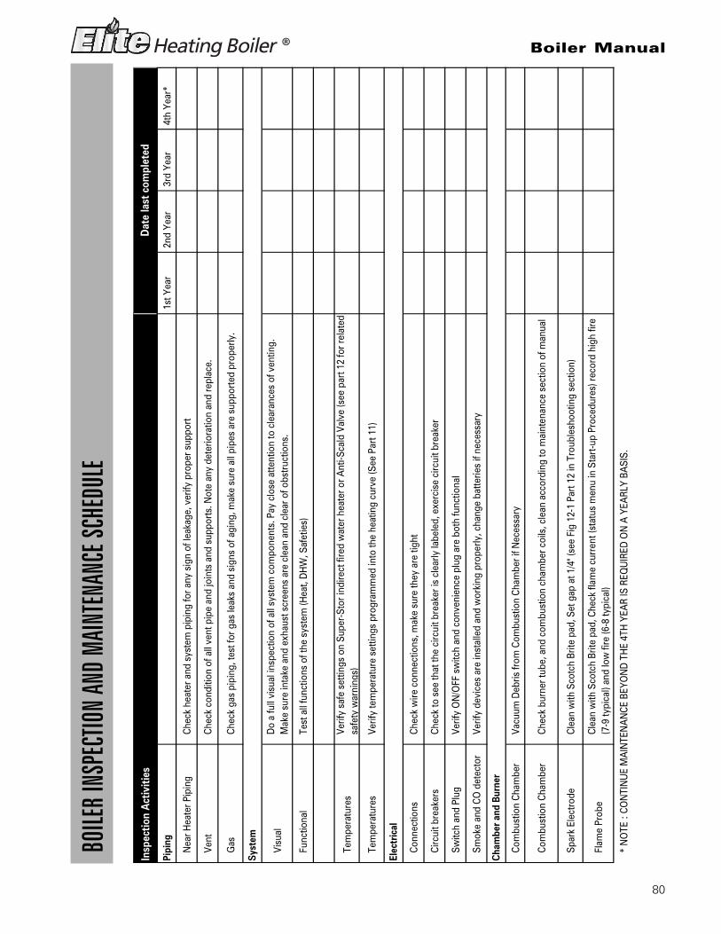
80
Boiler Manual
BOILE
R INS
PECT
ION
AND
MAIN
TENA
NCE S
CHED
ULE
Insp
ectio
n A
ctiv
ities
Pipi
ng 1
st Y
ear
2nd
Yea
r 3
rd Y
ear
4th
Yea
r*
Nea
r Hea
ter P
ipin
gCh
eck
heat
er a
nd s
yste
m p
ipin
g fo
r any
sig
n of
leak
age,
ver
ify p
rope
r sup
port
Vent
Chec
k co
nditi
on o
f all
vent
pip
e an
d jo
ints
and
sup
ports
. Not
e an
y de
terio
ratio
n an
d re
plac
e.
Gas
Chec
k ga
s pi
ping
, tes
t for
gas
leak
s an
d si
gns
of a
ging
, mak
e su
re a
ll pi
pes
are
supp
orte
d pr
oper
ly.
Visu
alD
o a
full
visu
al in
spec
tion
of a
ll sy
stem
com
pone
nts.
Pay
clo
se a
ttent
ion
to c
lear
ance
s of
ven
ting.
M
ake
sure
inta
ke a
nd e
xhau
st s
cree
ns a
re c
lean
and
cle
ar o
f obs
truct
ions
.
Func
tiona
lTe
st a
ll fu
nctio
ns o
f the
sys
tem
(Hea
t, D
HW
, Saf
etie
s)
Tem
pera
ture
sVe
rify
safe
set
tings
on
Supe
r-St
or in
dire
ct fi
red
wat
er h
eate
r or A
nti-S
cald
Val
ve (s
ee p
art 1
2 fo
r rel
ated
sa
fety
war
ning
s)
Tem
pera
ture
sVe
rify
tem
pera
ture
set
tings
pro
gram
med
into
the
heat
ing
curv
e (S
ee P
art 1
1)
Conn
ectio
nsCh
eck
wire
con
nect
ions
, mak
e su
re th
ey a
re ti
ght
Circ
uit b
reak
ers
Chec
k to
see
that
the
circ
uit b
reak
er is
cle
arly
labe
led,
exe
rcis
e ci
rcui
t bre
aker
Switc
h an
d Pl
ugVe
rify
ON
/OFF
sw
itch
and
conv
enie
nce
plug
are
bot
h fu
nctio
nal
Smok
e an
d CO
det
ecto
rVe
rify
devi
ces
are
inst
alle
d an
d w
orki
ng p
rope
rly, c
hang
e ba
tterie
s if
nece
ssar
y
Com
bust
ion
Cham
ber
Vacu
um D
ebris
from
Com
bust
ion
Cham
ber i
f Nec
essa
ry
Com
bust
ion
Cham
ber
Chec
k bu
rner
tube
, and
com
bust
ion
cham
ber c
oils
, cle
an a
ccor
ding
to m
aint
enan
ce s
ectio
n of
man
ual
Spar
k El
ectro
deCl
ean
with
Sco
tch
Brite
pad
, Set
gap
at 1
/4" (
see
Fig
12-1
Par
t 12
in T
roub
lesh
ootin
g se
ctio
n)
Flam
e Pr
obe
Clea
n w
ith S
cotc
h Br
ite p
ad, C
heck
flam
e cu
rren
t (st
atus
men
u in
Sta
rt-up
Pro
cedu
res)
reco
rd h
igh
fire
(7-9
typi
cal)
and
low
fire
(6-8
typi
cal)
* N
OTE
: CO
NTI
NU
E M
AIN
TEN
AN
CE B
EYO
ND
TH
E 4T
H Y
EAR
IS R
EQU
IRED
ON
A Y
EARL
Y BA
SIS.
Dat
e la
st c
ompl
eted
Syst
em
Elec
tric
al
Cha
mbe
r and
Bur
ner

81
Boiler Manual
BOILE
R INS
PECT
ION
AND
MAIN
TENA
NCE S
CHED
ULE (
CONT
INUE
D)
1st
Yea
r 2
Yea
r 3
Yea
r 4
Yea
r*
Cond
ensa
te N
eutra
lizer
Chec
k co
nden
sate
neu
traliz
er, m
akin
g su
re th
ere
is a
suf
ficie
nt q
uant
ity o
f chi
ps. R
eple
nish
if
nece
ssar
y.
Cond
ensa
te S
yste
m
1. C
heck
ent
ire c
onde
nsat
e sy
stem
mak
ing
sure
ther
e ar
e no
obs
truct
ions
in th
e flo
w
2. M
ake
sure
the
cond
ensa
te p
ump
is w
orki
ng p
rope
rty, v
erify
all
conn
ectio
ns.
3. C
lean
out
con
dens
ate
neut
raliz
er, u
se W
et /
Dry
Vac
uum
. Che
ck fo
r all
pote
ntia
l obs
truct
ion
issu
es.
Repl
enis
h m
arbl
e ch
ips
or li
me
crys
tals
if n
eede
d (n
o sm
alle
r tha
n ¾
”) R
efill
sys
tem
with
wat
er
WA
RNIN
G: Y
ou m
ust v
erify
flow
of c
onde
nsat
e an
d m
ake
sure
the
cap
is c
onne
cted
pro
perly
bef
ore
leav
ing
boile
r una
ttend
ed.
Pres
sure
M
easu
re in
com
ing
gas
pres
sure
(fro
m 3
.5" t
o 14
" W.C
.)
Pres
sure
Dro
pM
easu
re d
rop
in p
ress
ure
on li
ght o
ff (n
o m
ore
than
1" W
.C.)
Chec
k ga
s pi
pe fo
r lea
ksCh
eck
pipi
ng fo
r lea
ks, a
nd v
erify
they
are
all
prop
erly
sup
porte
d
Chec
k CO
/CO
2 Le
vels
Chec
k le
vels
of C
O a
nd C
O2
in E
xhau
st (S
ee s
tart
up s
ectio
n 11
fig
11-3
for r
ange
s) re
cord
at h
igh
and
low
fire
ECO
(Ene
rgy
Cut O
ut)
Chec
k co
ntin
uity
on
Flue
and
Wat
er E
CO, r
epla
ce if
cor
rode
d
Ther
mis
tors
Chec
k w
iring
, ver
ify th
roug
h oh
ms
read
ing
(see
cha
rt pa
rt 12
Fig
. 12-
2)
Chec
k Li
stVe
rify
that
you
hav
e co
mpl
eted
the
entir
e ch
eck
list W
ARN
ING
: FA
ILU
RE T
O D
O S
O C
OU
LD R
ESU
LT
IN D
EATH
OR
SERI
OU
S IN
JURY
.
Hom
eow
ner
Revi
ew, w
ith th
e ho
meo
wne
r wha
t you
hav
e do
ne
INIT
INIT
INIT
INIT
Tech
Sig
n O
ff
DA
TE
DA
TE
DA
TE
DA
TE
* N
OTE
: CO
NTI
NU
E M
AIN
TEN
AN
CE B
EYO
ND
TH
E 4T
H Y
EAR
IS R
EQU
IRED
ON
A Y
EARL
Y BA
SIS.
Con
dens
ate
Gas
Com
bust
ion
Safe
ties
Dat
e la
st c
ompl
eted
Insp
ectio
n A
ctiv
ities
Fina
l Ins
pect
ion

82
LP-172REV. 2/16/06

83
LP-172REV. 2/16/06

84
MAINTENANCE NOTES

85
MAINTENANCE NOTES

86
MAINTENANCE NOTES

© 2003–2010 Heat Transfer Products, Inc.www.HTproducts.com LP-293 REV. 3/1/10