flood-inundation maps for the mississinewa river at marion ... · flood-inundation maps for the...
TRANSCRIPT
Prepared in cooperation with the Indiana Office of Community and Rural Affairs
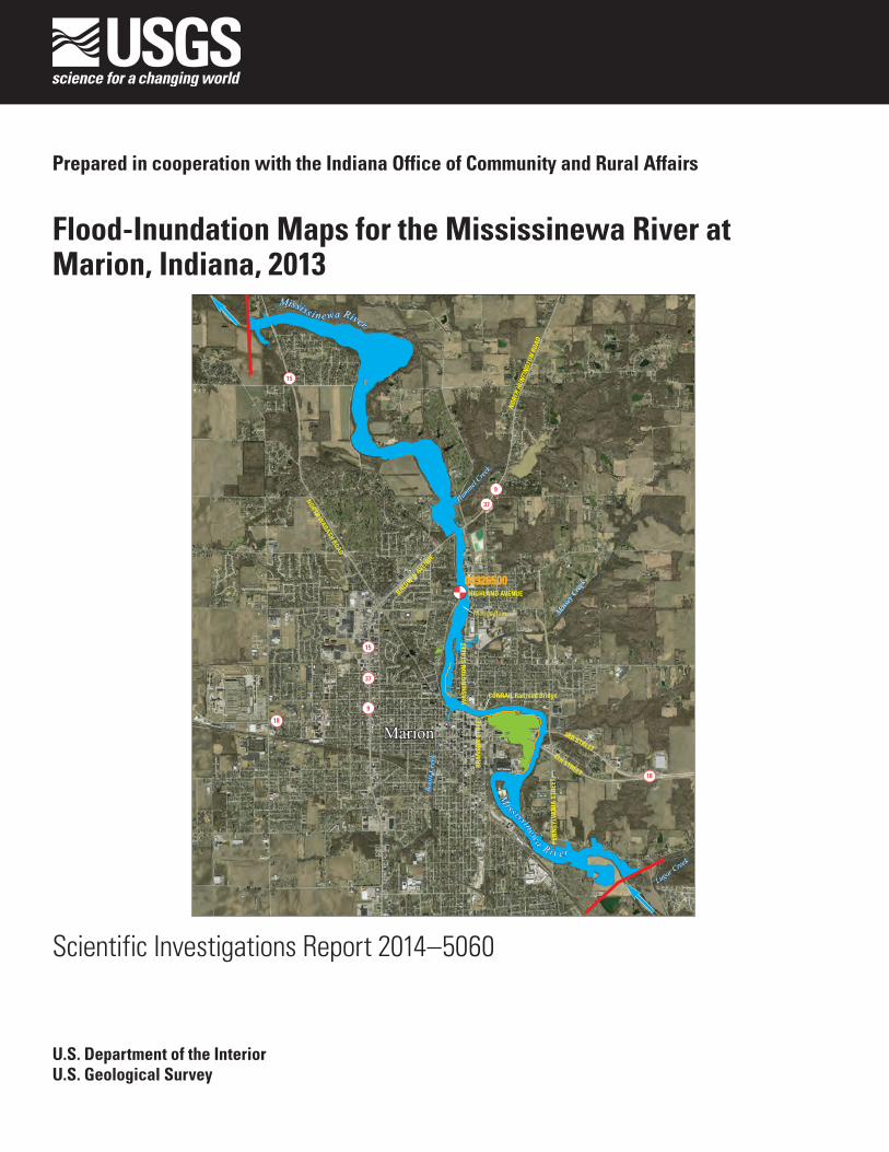
Flood-Inundation Maps for the Mississinewa River at Marion, Indiana, 2013
Lugar Cree
k
Boot
s Cre
ek
Hummel
Creek
Massey
Cree
k
Massey
Cree
k
Mississinewa R i v er
Mississ i newa River
03326500
15
18
18
9
37
15
37
9
HIGHLAND AVENUE
WA
SHIN
GTO
N S
TREE
T
BRA
NSO
N S
TREE
T
NORTH WABASH ROAD
PEN
NSY
LVA
NIA
STR
EET
3RD STREET4TH STREET
BALDW
IN AVENUE
NOR
TH H
UNTI
NGT
ON R
OAD
Marion Dam
CONRAIL Railroad Bridge
Marion
Scientific Investigations Report 2014–5060
U.S. Department of the InteriorU.S. Geological Survey

Cover: Illustration showing the simulated flood-inundation map corresponding to a streamgage stage of 16 feet for Mississinewa River at Marion, Indiana.

Flood-Inundation Maps for the Mississinewa River at Marion, Indiana, 2013
By William F. Coon
Prepared in cooperation with the Indiana Office of Community and Rural Affairs
Scientific Investigations Report 2014–5060
U.S. Department of the InteriorU.S. Geological Survey

U.S. Department of the InteriorSALLY JEWELL, Secretary
U.S. Geological SurveySuzette M. Kimball, Acting Director
U.S. Geological Survey, Reston, Virginia: 2014
For more information on the USGS—the Federal source for science about the Earth, its natural and living resources, natural hazards, and the environment, visit http://www.usgs.gov or call 1–888–ASK–USGS.
For an overview of USGS information products, including maps, imagery, and publications, visit http://www.usgs.gov/pubprod
To order this and other USGS information products, visit http://store.usgs.gov
Any use of trade, firm, or product names is for descriptive purposes only and does not imply endorsement by the U.S. Government.
Although this information product, for the most part, is in the public domain, it also may contain copyrighted materials as noted in the text. Permission to reproduce copyrighted items must be secured from the copyright owner.
Suggested citation:Coon, W.F., 2014, Flood-inundation maps for the Mississinewa River at Marion, Indiana, 2013: U.S. Geological Survey Scientific Investigations Report 2014-5060, 13 p., also available at http://dx.doi.org/sir/2014/5060.
ISSN 2328-0328 (online)http://dx.doi.org/10.3133/sir20145060

iii
Contents
Abstract ...........................................................................................................................................................1Introduction ....................................................................................................................................................1
Purpose and Scope ..............................................................................................................................2Study Area Description ........................................................................................................................4Previous Studies ...................................................................................................................................4
Constructing Water-Surface Profiles .........................................................................................................5Hydrologic and Steady-State Flow Data ...........................................................................................5Topographic and Bathymetric Data ...................................................................................................5Hydraulic Structures ............................................................................................................................6Energy-Loss Factors .............................................................................................................................6Model Calibration and Performance .................................................................................................7Development of Water-Surface Profiles ...........................................................................................9
Development of Flood-Inundation Maps .................................................................................................10Flood-Inundation Maps on the Internet ..........................................................................................10Disclaimer for Flood-Inundation Maps ...........................................................................................10Uncertainties and Limitations Regarding Use of Flood-Inundation Maps ................................10
Summary........................................................................................................................................................12References Cited..........................................................................................................................................13
Figures
1. Map showing location of study reach for the Mississinewa River at Marion, Indiana, and location of U.S. Geological Survey streamgage ...............................................3
2. Graph showing observed and simulated water-surface elevations and profiles for the flood of February 24, 1985, and the FEMA 10 percent annual exceedance probability flood for Mississinewa River at Marion, Indiana ................................................8
3. Graph showing observed and simulated water-surface elevations and profiles for the floods of January 23, 1999, and June 11, 1958, for Mississinewa River at Marion, Indiana .............................................................................................................................9
4. Flood-inundation map for the Mississinewa River at Marion, Indiana, correspond- ing to a stage of 16.00 feet at the U.S. Geological Survey streamgage .............................11
Tables
1. U.S. Geological Survey streamgage information for Mississinewa River at Marion, Indiana ............................................................................................................................................2
2. Peak discharges for selected annual exceedance probabilities for Mississinewa River at Marion, Indiana ..............................................................................................................4
3. Estimated discharges, in cubic feet per second, for corresponding stages and water-surface elevations at selected locations along the Mississinewa River, Marion, Indiana .............................................................................................................................5

iv
Tables—continued
4. Calibration of model to target water-surface elevations at U.S. Geological Survey streamgage on Mississinewa River at Marion, Indiana ........................................................7
5. Peak flows for which water-surface profiles have been surveyed or computed and were used to calibrate the hydraulic model for Mississinewa River at Marion, Indiana. ...........................................................................................................................................7
Conversion Factors
Inch/Pound to SI
Multiply By To obtain
Length
foot (ft) 0.3048 meter (m)mile (mi) 1.609 kilometer (km)
Area
square mile (mi2) 2.590 square kilometer (km2)Flow rate
cubic foot per second (ft3/s) 0.02832 cubic meter per second (m3/s)
Vertical coordinate information is referenced to either (1) stage, the height above an arbitrary datum established at a streamgage, or (2) elevation, the height above the North American Vertical Datum of 1988 (NAVD 88).
Horizontal coordinate information is referenced to the North American Datum of 1983 (NAD 83).
Acknowledgments
The author wishes to thank the Indiana Office of Community and Rural Affairs, which has coop-erated in the funding for the operation and maintenance of the gage used for this study. Darrin Miller of the Indiana Department of Natural Resources provided high-water elevations from his-toric floods that were used to calibrate the hydraulic model. Michael Graft of the City of Marion Engineering Department provided information on the levees in the City of Marion. Mr. Miller, Mr. Graft, and Bruce Bender, Director of the Grant County Emergency Management Agency, reviewed and provided valuable feedback on the flood-inundation maps. Several community members, including Maria Stefanovic of Hotel Marion, Scott Suever of Blinn Auto Sales, and Eric Whitton of Fastenal, Inc., provided clarification on the extent and depth of recent flooding in the central-eastern part of Marion. Special thanks are given to the National Weather Service for their continued support of the U.S. Geological Survey flood-inundation mapping initiative.

Flood-Inundation Maps for the Mississinewa River at Marion, Indiana, 2013
By William F. Coon
Abstract
Digital flood-inundation maps for a 9-mile (mi) reach of the Mississinewa River from 0.75 mi upstream from the Pennsylvania Street bridge in Marion, Indiana, to 0.2 mi downstream from State Route 15 were created by the U.S. Geological Survey (USGS) in cooperation with the Indiana Office of Community and Rural Affairs. The flood inunda-tion maps, which can be accessed through the USGS Flood Inundation Mapping Science Web site at http://water.usgs.gov/osw/flood_inundation/, depict estimates of the areal extent and depth of flooding corresponding to selected water levels (stages) at the USGS streamgage on the Mississinewa River at Marion (station number 03326500). Near-real-time stages at this streamgage may be obtained on the Internet from the USGS National Water Information System at http://waterdata.usgs.gov/ or the National Weather Service (NWS) Advanced Hydrologic Prediction Service at http:/water.weather.gov/ahps/, which also forecasts flood hydrographs at this site.
Flood profiles were computed for the stream reach by means of a one-dimensional step-backwater model. The model was calibrated by using the current stage-discharge relation at the Mississinewa River streamgage, in combina-tion with water-surface profiles from historic floods and from the current (2002) flood-insurance study for Grant County, Indiana. The hydraulic model was then used to compute seven water-surface profiles for flood stages at 1-foot (ft) intervals referenced to the streamgage datum and ranging from 10 ft, which is near bankfull, to 16 ft, which is between the water levels associated with the estimated 10- and 2-percent annual exceedance probability floods (floods with recurrence intervals between 10 and 50 years) and equals the “major flood stage” as defined by the NWS. The simulated water-surface profiles were then combined with a Geographic Information System digital elevation model (derived from light detection and rang-ing (lidar) data having a 0.98 ft vertical accuracy and 4.9 ft horizontal resolution) to delineate the area flooded at each water level.
The availability of these maps, along with Internet infor-mation regarding current stage from the USGS streamgage and
forecasted high-flow stages from the NWS, will provide emer-gency management personnel and residents with information that is critical for flood response activities such as evacuations and road closures, as well as for post-flood recovery efforts.
Introduction
The City of Marion, in Grant County, Indiana (Ind.), is a sizeable urban community with an estimated population of 29,948 (U.S. Bureau of the Census, 2010). The Missis-sinewa River, which flows northwestward through the city, has severely flooded numerous times in the past. Peak flows have been recorded since September 1923 at the U.S. Geologi-cal Survey (USGS) streamgage on the Mississinewa River at Marion (station number 03326500). Before this time, Marion experienced its largest documented flood during March 1913 (Federal Emergency Management Agency, 2010) when the river rose to a stage of 19.4 feet (ft), gage datum (793.3 ft, North American Vertical Datum of 1988, NAVD 88); how-ever, the discharge for this flood was not determined. Since September 1923, peak flows on the Mississinewa River have exceeded the Federal Emergency Management Agency (FEMA; 2002) 10-percent annual exceedance probability flood (10-year recurrence interval flood) of 19,800 cubic feet per second (ft3/s) eight times (during 1927, 1933, 1943, 1958, 1990, 1998, 1999, and 2005). Of these, the highest peak flows were 25,000 ft3/s on March 21, 1927, at a stage of 17.40 ft (791.54 ft, NAVD 88) and 24,300 ft3/s on June 11, 1958, at a stage of 16.88 ft (791.02 ft, NAVD 88).
Prior to this study, emergency responders in Grant County relied on several information sources (all of which are available on the Internet) to make decisions on how to best alert the public and mitigate flood damages. One source is the FEMA flood insurance study (FIS) for Grant County, which includes the City of Marion, dated May 15, 2002 (Federal Emergency Management Agency, 2002). An updated, prelimi-nary (yet-to-be-approved) version of the FIS (Federal Emer-gency Management Agency, 2010), which includes informa-tion on three additional townships, is available through the

2 Flood-Inundation Maps for the Mississinewa River at Marion, Indiana, 2013
Indiana Department of Natural Resources (IDNR; 2013a). A second source of information is the USGS streamgage, Missis-sinewa River at Marion, from which current (U.S. Geological Survey, 2013a) and historical (since 1923; U.S. Geological Survey, 2013b) water levels and discharges, including annual peak flows, can be obtained. A third source of flood-related information is the National Weather Service (NWS) Advanced Hydrologic Prediction Service (AHPS), which also displays the USGS stage data from the Marion streamgage (National Weather Service, 2013a). The NWS does not routinely issue forecasts at the Mississinewa River streamgage at Marion, but it does so as needed during times of high-stage flows.
Although the current stage at a USGS streamgage is particularly useful for residents in the immediate vicinity of a streamgage, it is of limited use to residents farther upstream or downstream because the water-surface elevation is not constant along the entire stream reach. Knowledge of a water level at a streamgage is difficult to translate into depth and areal extent of flooding at points distant from the streamgage. One way to address these informational gaps is to produce a library of flood-inundation maps that are referenced to the stages recorded at the USGS streamgage. By referring to the appropriate map, emergency responders can discern the sever-ity of flooding (depth of water and areal extent), identify roads that are or will soon be flooded, and make plans for notifica-tion or evacuation of residents in harm’s way for some dis-tance upstream and downstream from the streamgage. In addi-tion, the capability to visualize the potential extent of flooding has been shown to motivate residents to take precautions and heed warnings that they previously might have disregarded. In 2011–13, the USGS, in cooperation with the Indiana Office of Community and Rural Affairs, conducted a project to produce a library of flood-inundation maps for the Mississinewa River at Marion, Ind.
Purpose and Scope
The purpose of this report is to describe the develop-ment of a series of estimated flood-inundation maps for the Mississinewa River at Marion, Ind., and to present the maps, which are available on the USGS Flood Inundation Map-ping Science Web site (U.S. Geological Survey, 2013c). The flood-inundation maps cover a reach about 9 miles (mi) long, from 0.75 mi upstream from the Pennsylvania Street bridge in Marion to 0.2 mi downstream from State Route 15 (SR 15, North Wabash Road; fig. 1). The maps were produced for flood levels referenced to the stage recorded at the USGS streamgage on the Mississinewa River at Marion (03326500; table 1), which is about midway through the study reach. The maps cover a range in stage from 10 to 16 ft, gage datum. The 10-ft stage is approximately bankfull and is defined by the NWS (2013b) as the “action stage” or that stage which, when reached by a rising stream, requires the NWS or a partner to take some type of mitigation action in preparation for possible significant hydrologic activity. The 16-ft stage is between the water levels associated with the estimated 10- and 2-percent annual exceedance probability floods (floods with recurrence intervals between 10 and 50 years) and equals the “major flood stage” as defined by the NWS.
Tasks specific to development of the flood maps for the Mississinewa River at Marion included (1) collection of topographic and bathymetric data for selected cross sections and geometric data for structures and bridges along the study reach, (2) estimation of energy-loss factors (roughness coef-ficients) in the stream channel and flood plain and determina-tion of steady-flow data, (3) computation of water-surface profiles using the U.S. Army Corps of Engineers’ HEC–RAS computer program (U.S. Army Corps of Engineers, 2010),
Table 1. U.S. Geological Survey streamgage information for Mississinewa River at Marion, Indiana.
[Station location is shown in figure 1. ft3/s, cubic feet per second; NAVD 88, North American Vertical Datum of 1988]
Station name
tation number
rainage area (square miles)
atitude
ongitude
eriod of record (water years1)
aximum recorded stage, in feet, gage datum (and elevation feet above NAVD 88) during period of record and date
aximum discharge, in ft3/s, during period of record and dat
eak stage, in feet, gage datum (and elevation, in feet above
Mississinewa River at Marion, IndianaS 03326500D 682L 40°34′35″L 85°39′36″P 1924–2012M , in
17.40 (791.54) on March 21, 1927
M e 25,000 on March 21, 1927PNAVD 88) outside of period of record during March 1913
19.20 (793.34) Discharge unknown.
1 Water year is the 12-month period from October 1 of one year through September 30 of the following year and is designated by the calendar year in which it ends.

Introduction 3
85°38'85°39'85°40'85°41'85°42'
40°36'
40°35'
40°34'
40°33'
Lugar Cree
k
Boot
s Cre
ek
Hummel
Creek
Massey
Cree
k
Massey
Cree
k
Mississinewa R i v er
Mississ i newa River
03326500
15
18
9
18
37
15
37
9
HIGHLAND AVENUE
WA
SHIN
GTO
N S
TREE
T
BRA
NSO
N S
TREE
T
NORTH WABASH ROAD
PEN
NSY
LVA
NIA
STR
EET
3RD STREET4TH STREET
BALDW
IN AVENUE
NOR
TH H
UNTI
NGT
ON R
OAD
Figure 1. Location of study reach for the Mississinewa River at Marion, Indiana, and location of U.S. Geological Survey streamgage
Marion Dam
CONRAIL Railroad Bridge
Marion
Projection: Indiana State Plane Eastern Zone, Horizontal coordinate information is referenced to the North American Datum of 1983Orthophotgraphy from Indiana Spatial Data Portal, Indiana Orthophotography (RGBI), LiDAR and Elevation Program, 2012, available at http://gis.iu.edu
EXPLANATION
03326500
15
Limit of study area
Stream
Levee
Flow arrow—Indicates direction of water flow
U.S. Geological Survey streamgage and number
State route marker
0 1 2 MILES
0 1 2 KILOMETERS
INDIANA
GRANT COUNTY
Study area
Figure 1. Location of study reach for the Mississinewa River at Marion, Indiana, and location of U.S. Geological Survey streamgage.

4 Flood-Inundation Maps for the Mississinewa River at Marion, Indiana, 2013
(4) production of estimated flood-inundation maps at various stream stages using the U.S. Army Corps of Engineers’ HEC-GeoRAS computer program (U.S. Army Corps of Engineers, 2009) and a Geographic Information System (GIS), and (5) preparation of the maps, both as shapefile polygons that depict the areal extent of flood inundation and as depth grids that provide the depth of floodwaters, for display on a USGS flood inundation mapping application. Techniques that varied substantially from previously documented methods because of local hydrologic conditions or available data are described in detail in this report.
Study Area Description
The Mississinewa River, in the northeastern quarter of Indiana, rises in west-central Ohio and flows westward through Randolph County in Indiana. In Delaware County the river turns northwestward and flows in this general direction through Grant and Wabash Counties until, in Miami County, it joins the Wabash River just east of the City of Peru. The drainage area of the Mississinewa River Basin is 682 square miles at the USGS streamgage at Marion, which is 35.8 mi upstream from the mouth. Several minor tributaries, includ-ing Boots Creek, Massey Creek, and Hummel Creek, join the Mississinewa River within the study reach. A fourth tributary, Lugar Creek, joins the Mississinewa River just upstream from the upstream study limit.
The study reach is approximately 9 mi long and has an average top-of-bank channel width of 220 ft. The average channel slope through the reach is 0.00059, whereas the high-water-surface slope is about 0.00065. The main channel within the study reach is traversed by eight roadways, a railroad, and a low-head dam. The river banks and most of the area adjacent to the river throughout the study reach are forested. The flood plain within the City of Marion is dominated by
residential and commercial development. Elsewhere, the flood plain is mostly forested but includes some agricultural land. An earthen levee runs along the western bank in the City of Marion between Pennsylvania Street and Highland Avenue. This levee has not been well maintained, but it does afford some flood protection to the properties in this densely devel-oped area, at least, along some segments of the reach and to the point that the levee is overtopped (M. Graft, City of Marion, Engineering Department, oral commun., 2013). The overall effectiveness of this levee is unknown; therefore, it was not simulated as a levee in the hydraulic model that was developed for this study.
Previous Studies
The current FIS for Grant County (Federal Emergency Management Agency, 2002) is a compilation of earlier com-munity FISs, including those for the City of Marion (Federal Emergency Management Agency, 1982) and the unincorpo-rated areas of Grant County (Federal Emergency Management Agency, 1986), as well as detailed studies of selected known flood-hazard areas. Presently (June 2013), a preliminary version of a revised and updated countywide FIS is being developed and will include additional flood-hazard areas that will be studied by detailed, as well as approximate, methods (Federal Emergency Management Agency, 2010). The 1980s hydraulic models for the Mississinewa River in Marion are the basis for the data presented in the current (2002) and pre-liminary (2010) FISs. The FIS presents estimates of the peak discharges with 10-, 2-, 1-, and 0.2-percent annual exceedance probabilities and their associated water-surface elevations for the USGS streamgage, Mississinewa River at Marion, just downstream from the Highland Avenue bridge. These flood frequencies are presented in table 2.
Table 2. Peak discharges for selected annual exceedance probabilities for Mississinewa River at Marion, Indiana (station number 03326500).
[ft3/s, cubic feet per second; FEMA, Federal Emergency Management Agency; NAVD 88, North American Vertical Datum of 1988; USGS, U.S. Geological Survey; —, no data]
Annual exceedance probability
(percent)
Discharge1 (ft3/s)
FEMA water-surface
elevation1 (feet, NAVD 88)
USGS water-surface
elevation (feet, NAVD 88)
Difference in elevation
(feet)
10 19,800 788.7 789.3 2 0.62 28,100 791.2 3 —1 31,800 792.2 3 —0.2 39,000 793.8 3 —
1 Data from Federal Emergency Management Agency, 2002. Discharges from Table 7; water-surface elevations from Flood-Profile Panel 11.2 Value from most recent stage-discharge relation (number 41, dated July 24, 2011) for Mississinewa River at Marion, Indiana.3 Water-surface elevation for associated discharge exceeds stage-discharge relation.

Constructing Water-Surface Profiles 5
Constructing Water-Surface Profiles
Water-surface profiles that were used to produce the seven flood-inundation maps in this study were computed by using HEC–RAS, version 4.1.0 (U.S. Army Corps of Engi-neers, 2010). HEC–RAS is a one-dimensional step-backwater model for simulation of water-surface profiles with steady-state (gradually varied) or unsteady-state flow computation options.
Hydrologic and Steady-State Flow Data
The study reach includes one streamgage (03326500; fig. 1; table 1) that has been in operation since September 1923. Stage is measured every 15 minutes, transmitted hourly by a satellite radio in the gage, and made available on the Inter-net through the USGS National Water Information System (NWIS; U.S. Geological Survey, 2013a). Stage data from this gage are referenced to a local datum but can be converted to water-surface elevations referenced to the NAVD 88 by adding 774.14 ft. Continuous records of streamflow are computed from a stage-discharge relation that has been developed for the streamgage and also are available through the USGS NWIS Web site.
The HEC–RAS analysis for this study was done by using the steady-state flow computation option. Steady-state flow data consisted of flow regime, boundary conditions (either known stage associated with a discharge measurement, criti-cal depth, normal depth, or a streamgage rating-curve value), and peak flows that produced water-surface elevations at the streamgage cross section that matched target water-surface elevations. These target elevations coincided with even 1-ft increments of stage, referenced to the local gage datum. Subcritical (tranquil) flow regime was assumed for the simula-tions. Normal depth was used as the downstream boundary condition of the reach. The slope required for calculation of
normal depth was computed from the water-surface elevations that were surveyed at the downstream end of the study reach following the historic floods of February 10, 1959, and June 11, 1958 (D. Miller, Indiana Department of Natural Resources, written commun., 2013). These flood magnitudes, 14,500 ft3/s and 24,300 ft3/s, respectively, are within or close to the range of flows simulated for the flood-inundation maps. The com-puted slope was adjusted as necessary so that simulated water-surface elevations at the downstream end of the study reach approximated the few observed elevations that were available for calibration from historic floods.
The peak flows used in the model simulations (table 3) were taken from the current stage-discharge relation at the USGS streamgage (number 41, effective July 24, 2011) and corresponded with the target water-surface elevations. Three minor tributaries—Boots Creek, Massey Creek, and Hummel Creek—join the Mississinewa River within the 9-mi study reach. The streamgage-derived discharges were adjusted, as necessary, to account for tributary inflows (table 3). These adjustments were equal to those applied in the currently effec-tive FIS (Federal Emergency Management Agency, 2002) for the four largest simulated flows; the adjustments were decreased for the three lowest simulated flows.
Topographic and Bathymetric Data
All topographic data used in this study are referenced vertically to NAVD 88 and horizontally to the North American Datum of 1983. Cross-section elevation data were obtained from a digital elevation model (DEM) that was derived from light detection and ranging (lidar) data that were collected as part of a statewide project during 2011–13 by Woolpert, Inc., Geospatial Services, Dayton, Ohio. Lidar data for Grant County were collected between January 31 and December 13, 2012. The DEM was obtained from the Indiana Spatial Data Portal (Indiana University, 2013).
Table 3. Estimated discharges, in cubic feet per second, for corresponding stages and water-surface elevations at selected locations along the Mississinewa River, Marion, Indiana.
[NAVD 88, North American Vertical Datum of 1988; USGS, U.S. Geological Survey]
Location
Stage, in feet above gage datum (elevation, in feet above NAVD 88)1
10 (784.14)
11 (785.14)
12 (786.14)
13 (787.14)
14 (788.14)
15 (789.14)
16 (790.14)
Upstream limit of study reach2 (downstream from Lugar Creek)
10,020 11,710 13,490 15,310 17,260 19,290 21,390
Downstream from Boots Creek3 10,170 11,860 13,640 15,510 17,460 19,490 21,590Downstream from Hummel Creek2 10,240 11,940 13,720 15,610 17,560 19,590 21,690
1 Stages and water-surface elevations are in 1-foot increments, referenced to the USGS streamgage Mississinewa River at Marion (station number 03326500).
2 Discharges from stage-discharge relation for USGS streamgage Mississinewa River at Marion (at Highland Avenue) adjusted for tributary inflow on the basis of data in Federal Emergency Management Agency (2002).
3 Discharges from stage-discharge relation for USGS streamgage Mississinewa River at Marion (at Highland Avenue) (station number 03326500).

6 Flood-Inundation Maps for the Mississinewa River at Marion, Indiana, 2013
The original lidar data have horizontal resolution of 4.9 ft (1.5 meters) and vertical accuracy of 0.98 ft (30 centimeters) at a 95 percent confidence level based on a root mean squared error of 0.49 ft (15 centimeters) for the “open terrain” land-cover category. By these criteria, the lidar data support produc-tion of 2-ft contours (Dewberry, 2012); the final DEM, which was resampled to a grid-cell size of 10 ft by 10 ft to decrease the GIS processing time, has a vertical accuracy of plus or minus 1 ft. By using HEC-GeoRAS—a set of procedures, tools, and utilities for processing geospatial data in ArcGIS—elevation data were extracted from the DEM for 128 synthetic cross sections, including 9 bridges and the Marion Dam (a low-head dam just upstream from the Highland Avenue bridge and the USGS streamgage), and subsequently were input to the HEC–RAS model.
Because lidar data cannot provide ground elevations below a stream’s water surface, channel cross sections were surveyed by USGS field crews during 2012. Cross sectional depths were measured by wading or by using hydroacoustic instrumentation at 46 locations. A differential global posi-tioning system with realtime kinematic technology was used to derive horizontal locations and the elevation of the water surface at each surveyed cross section.
In the ArcMap application of ArcGIS (Esri, 2012), these field data were used in conjunction with a bathymetry mesh tool that was created by Merwade and others (2008) to inter-polate below-water ground elevations through the study reach. The density of ground elevations in the mesh was determined by two variables: (1) the number of parallel longitudinal profiles that were evenly spaced across the channel and ran the length of the study reach and (2) the user-specified spac-ing between cross sections. Ground elevations were either extracted or interpolated from the field data at the intersections of 21 longitudinal profiles and cross sections that were spaced 250 ft apart. The mesh elevations were subsequently added to the DEM data of the synthetic cross sections before the data were exported to HEC–RAS. Instructions for the bathymetry mesh tool are presented by Merwade (2011).
Hydraulic Structures
Ten structures, consisting of eight road crossings, a rail-road bridge (owned by CSX Transportation), and the Marion Dam, have the potential to affect water-surface elevations during floods along the stream. Bridge-geometry data were obtained from field surveys conducted by personnel from the USGS Indiana Water Science Center. Elevation data for the Marion Dam were obtained from a HEC–2 model (U.S. Army Corps of Engineers, 1972; Indiana Department of Natural Resources, 2013b) that was developed by Gannett Fleming, Inc., and used for the 1982 FIS (Federal Emergency Manage-ment Agency, 1982). The elevation data were adjusted to NAVD 88 and stationing along the cross section was revised, as necessary, to agree with that in the DEM-derived cross section.
A naturally high bank or an earth-berm levee lines the west bank and, for short segments, the east bank of the Mis-sissinewa River in the City of Marion from Pennsylvania Street to Highland Avenue. The levee has not been maintained (M. Graft, City of Marion, Engineering Dept., oral commun., 2013), but it provides some protection from flooding, at least for short subreaches of the river. Because of the uncertainty as to the effectiveness of this levee, it was not simulated as a levee; rather, where appropriate to do so, the landward side of the levee was simulated as ineffective flow area up to the elevation of the top of the levee.
Energy-Loss Factors
Initial (precalibration) Manning’s roughness coefficients (n values) for energy-loss (friction-loss) calculations were estimated by comparison of field photographs with photo-graphs of channels for which n values have been computed and published in references, such as Barnes (1967) and Coon (1998). An n value of 0.035 was selected for the main chan-nel and 0.100 for the overbank areas, which are dominated by forests and agricultural fields in the rural sections of the study reach and by densely populated residential and commercial areas within the City of Marion.
The initial n values were adjusted as part of the calibra-tion process, which involved stepwise matching of simu-lated and observed water-surface elevations, starting at the downstream end of the study reach and moving upstream. Roughness-coefficient adjustment factors were varied by flow and adjusted until the simulated water-surface elevations approximated the observed water-surface elevations in the downstream half of the study reach (upstream to the bridge on SR 9 & 37). The actual n values were computed by multiply-ing the initial n value by each of the roughness-coefficient adjustment factors. These computed values were then input to the “vertical variation in n value” table for each cross section in this part of the study reach. Main channel n values ranged from 0.030 to 0.039, and overbank values ranged from 0.085 to 0.168. A similar process was followed for the subreach between SR 9 & 37 and the Marion Dam, which includes the USGS streamgage. Because the water-surface slope decreases substantially in this subreach, main channel n values had to be decreased in the range of 0.019 to 0.030 in order to hit the target elevations from the stage-discharge relation at the Highland Avenue streamgage. Overbank n values had no effect on water-surface elevations because no overbank flow occurred in this subreach. Upstream from the Marion Dam to the upstream end of the study reach, n values were no longer varied vertically. Rather, single values were used for all flows and increased from 0.031 in the subreach just upstream from the Marion Dam to 0.033 near the Washington Street bridge to 0.045, which was used for the upstream-most 1.4-mi segment of the study reach. Again, these values were used, and transi-tions were made, to minimize the differences between simu-lated and observed high-water marks.

Constructing Water-Surface Profiles 7
Model Calibration and Performance
The HEC–RAS model was calibrated to (1) the current stage-discharge relation for the Mississinewa River at Marion streamgage, (2) high-water elevations from three historic floods, and (3) the FEMA FIS water-surface elevations for the 10-percent annual exceedance probability (AEP) flood. Roughness coefficients and coefficients to account for energy losses due to expansion and contraction of flow at bridge con-strictions were adjusted to minimize the differences between simulated and observed (target) water-surface elevations. The maximum difference between observed and simulated water-surface elevations at the USGS streamgage, 03326500, for the seven simulated flows was 0.04 ft (table 4).
High-water elevations have been surveyed periodically by the IDNR, Division of Water (D. Miller, Indiana Depart-ment of Natural Resources, written commun., 2013) follow-ing past floods (table 5). These data were reviewed and those from three floods—June 1958, February 1985, and January 1999—were used to calibrate the hydraulic model. These floods cover flows in the range of 19,400 to 24,300 ft3/s and stages between 15.16 and 16.88 ft. Additional flood data were disregarded, because they were deemed incompatible with the current stage-discharge relation. A fourth flood profile, that for the 10-percent AEP flood, was obtained from the current FIS (Federal Emergency Management Agency, 2002). The station-ing of the IDNR high-water elevations was referenced to river miles upstream from the mouth of the Mississinewa River;
Table 4. Calibration of model to target water-surface elevations at U.S. Geological Survey streamgage on Mississinewa River at Marion, Indiana (station number 03326500).
[NAVD 88, North American Vertical Datum of 1988; ft3/s, cubic feet per second]
Water- surface profile1
Discharge, corresponding to
target water-surface elevation, in ft3/s
Target water-surface
elevation, in feet, NAVD 88
Simulated water-surface
elevation, in feet, NAVD 88
Difference in elevation,
in feet
10 10,170 784.14 784.14 0.0011 11,860 785.14 785.10 -0.0412 13,640 786.14 786.14 0.0013 15,510 787.14 787.10 -0.0414 17,460 788.14 788.18 0.0415 19,490 789.14 789.10 -0.0416 21,590 790.14 790.17 0.03
1Water-surface profiles are 1-foot increments of stage, referenced to the gage datum of the U.S. Geological Survey streamgage.
Table 5. Peak flows for which water-surface profiles have been surveyed or computed and were used to calibrate the hydraulic model for Mississinewa River at Marion, Indiana.
[ft3/s, cubic feet per second; USGS, U.S. Geological Survey; NAVD 88, North American Vertical Datum of 1988; FEMA, Federal Emergency Management Agency; AEP, annual exceedance probability; —, no data]
EventPeak flow
(ft3/s)
Peak stage at USGS gage,
in feet
Peak elevation at USGS gage,
in feet, NAVD 88
Number of high-water
elevations used
Simulated water-surface elevation
at USGS gage, in feet, NAVD 88
Difference in elevation,
in feet
February 24, 19851 19,400 15.16 789.30 18 789.06 -0.24FEMA 10-percent
AEP flood219,800 — 788.7 28 789.25 0.55
January 23, 19991 20,200 15.42 789.56 10 789.46 -0.10June 11, 19581 24,300 16.88 791.02 27 791.05 0.03
1 Data from D. Miller, Indiana Department of Natural Resources, written commun., 2013.2 Data from Federal Emergency Management Agency, 2002 and 2010.

8 Flood-Inundation Maps for the Mississinewa River at Marion, Indiana, 2013
whereas that for the FIS 10-percent AEP flood was referenced in feet upstream from the northern boundary of the City of Marion. Because the stationing used in the current HEC–RAS model was referenced in feet to an arbitrary origin about 4,200 ft downstream from SR 15, the stations for both the IDNR and FIS elevations were changed to agree with those in the model.
The February 24, 1985, water-surface elevations, for a flow of 19,400 ft3/s (stage of 15.16 ft), were compared with the computed elevations for the 10-percent AEP flood of 19,800 ft3/s (fig. 2). Additionally, each set of data was compared with the simulated profiles for their correspond-ing flows (fig. 2), which were essentially identical. The data for the 10-percent AEP flood were the only FIS data used for
model calibration because all greater AEP floods exceeded the range of flows for which flood-inundation maps were created (table 2). Noticeable discrepancies were found between these two sets of data (fig. 2), but preference was given to the 1985 data for calibration purposes because these data mimicked the general shape of the water-surface profiles that had been documented for higher floods (those of January 1999 and June 1958). The 10-percent AEP flood profile diverged from the surveyed water-surface profiles, except in the subreach between the Marion Dam and SR 18. Upstream and down-stream from this reach the 10-percent AEP water surface was lower than the 1985 surveyed high-water elevations (fig. 2).
760
770
780
790
800
810
820
830
840
0 5,000 10,000 15,000 20,000 25,000 30,000 35,000 40,000 45,000 50,000 55,000
Elev
atio
n ab
ove
Nor
th A
mer
ican
Ver
tical
Dat
um o
f 198
8, in
feet
Distance upstream from study-reach reference point, in feetVERTICAL SCALE GREATLY EXAGGERATED
Stat
e Ro
ute
18
Wes
tSt
ate
Rout
e 18
Eas
t
Stat
eRou
te 1
5
Stat
eRou
te 9
/ 37
Hig
hlan
d A
venu
e &
U.S
. Geo
logi
cal S
urve
y ga
ge
Was
hing
tonS
tree
tB
rans
on S
tree
tCS
XT R
ailro
ad
Penn
sylv
ania
Str
eet
Mar
ion
Dam
Hum
mel
Cre
ek
Mas
sey
Cree
k
Boo
ts C
reek
Luga
r Cre
ek
EXPLANATION
Observed water-surface elevations, Flood of February 1985
Simulated water-surface profile, Flood of February 1985
Computed water-surface elevations, FEMA 10-percent annual exceedance probability flood
Simulated water-surface profile, FEMA 10-percent annual exceedance probability flood
Figure 2. Observed and simulated water-surface elevations and profiles for the flood of February 24, 1985, and the Federal Emergency Management Agency 10-percent annual exceedance probability flood for Mississinewa River at Marion, Indiana.
Constructing Water-Surface Profiles 9
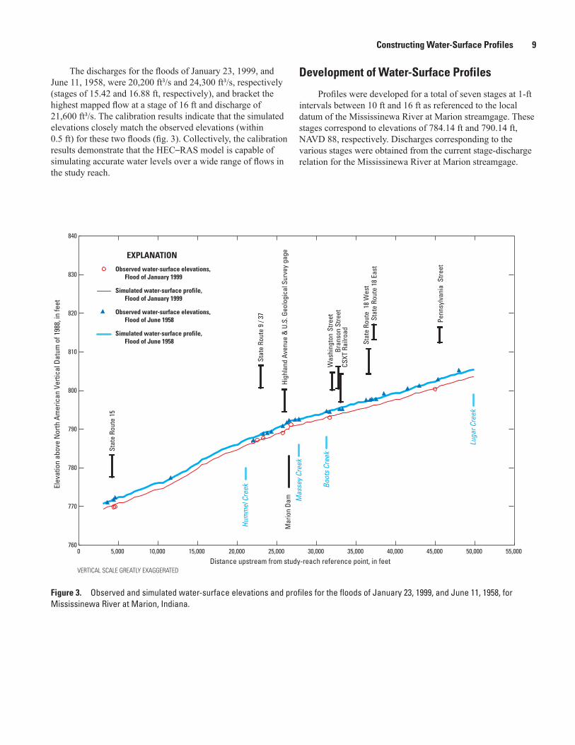
The discharges for the floods of January 23, 1999, and Development of Water-Surface Profiles
Profiles were developed for a total of seven stages at 1-ft intervals between 10 ft and 16 ft as referenced to the local datum of the Mississinewa River at Marion streamgage. These stages correspond to elevations of 784.14 ft and 790.14 ft, NAVD 88, respectively. Discharges corresponding to the various stages were obtained from the current stage-discharge relation for the Mississinewa River at Marion streamgage.
Mississinewa River at Marion, Indiana.
June 11, 1958, were 20,200 ft3/s and 24,300 ft3/s, respectively (stages of 15.42 and 16.88 ft, respectively), and bracket the highest mapped flow at a stage of 16 ft and discharge of 21,600 ft3/s. The calibration results indicate that the simulated elevations closely match the observed elevations (within 0.5 ft) for these two floods (fig. 3). Collectively, the calibration results demonstrate that the HEC–RAS model is capable of simulating accurate water levels over a wide range of flows in the study reach.
VERTICAL SCALE GREATLY EXAGGERATED
EXPLANATION
Observed water-surface elevations, Flood of January 1999
Simulated water-surface profile, Flood of January 1999
Observed water-surface elevations, Flood of June 1958
Simulated water-surface profile, Flood of June 1958
760
770
780
790
800
810
820
830
840
0 5,000 10,000 15,000 20,000 25,000 30,000 35,000 40,000 45,000 50,000 55,000
Elev
atio
n ab
ove
Nor
th A
mer
ican
Ver
tical
Dat
um o
f 198
8, in
feet
Distance upstream from study-reach reference point, in feet
Stat
eRo
ute
15
Stat
eRo
ute
9 / 3
7
Hig
hlan
d A
venu
e &
U.S
. Geo
logi
cal S
urve
y ga
ge
Was
hing
ton
Stre
etB
rans
on S
tree
tCS
XT R
ailro
ad
Stat
e Ro
ute
18
Wes
tSt
ate
Rout
e 18
Eas
t
Penn
sylv
ania
Str
eet
Mar
ion
Dam
Hum
mel
Cre
ek
Mas
sey
Cree
k
Boot
s Cr
eek
Luga
r Cre
ek
Figure 3. Observed and simulated water-surface elevations and profiles for the floods of January 23, 1999, and June 11, 1958, for
10 Flood-Inundation Maps for the Mississinewa River at Marion, Indiana, 2013
Development of Flood-Inundation Maps
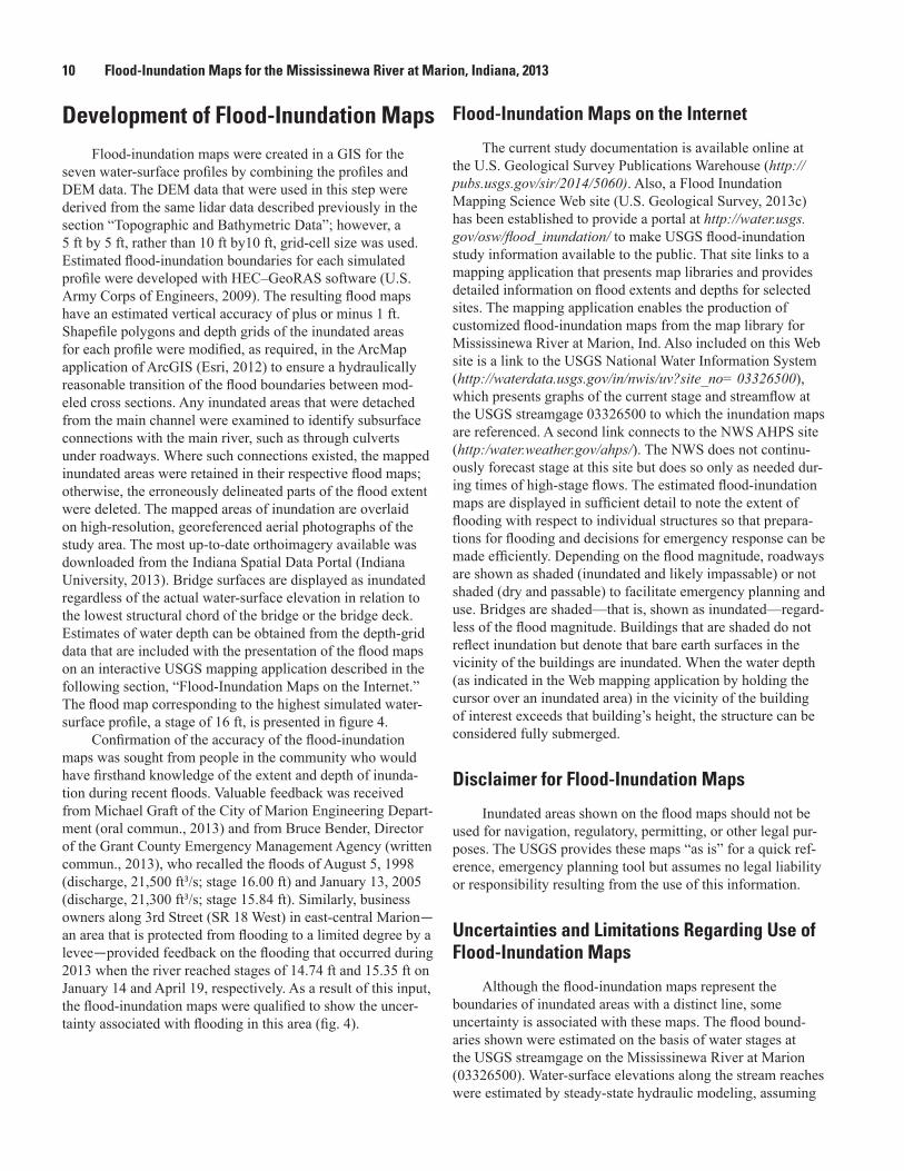
Flood-inundation maps were created in a GIS for the seven water-surface profiles by combining the profiles and DEM data. The DEM data that were used in this step were derived from the same lidar data described previously in the section “Topographic and Bathymetric Data”; however, a 5 ft by 5 ft, rather than 10 ft by10 ft, grid-cell size was used. Estimated flood-inundation boundaries for each simulated profile were developed with HEC–GeoRAS software (U.S. Army Corps of Engineers, 2009). The resulting flood maps have an estimated vertical accuracy of plus or minus 1 ft. Shapefile polygons and depth grids of the inundated areas for each profile were modified, as required, in the ArcMap application of ArcGIS (Esri, 2012) to ensure a hydraulically reasonable transition of the flood boundaries between mod-eled cross sections. Any inundated areas that were detached from the main channel were examined to identify subsurface connections with the main river, such as through culverts under roadways. Where such connections existed, the mapped inundated areas were retained in their respective flood maps; otherwise, the erroneously delineated parts of the flood extent were deleted. The mapped areas of inundation are overlaid on high-resolution, georeferenced aerial photographs of the study area. The most up-to-date orthoimagery available was downloaded from the Indiana Spatial Data Portal (Indiana University, 2013). Bridge surfaces are displayed as inundated regardless of the actual water-surface elevation in relation to the lowest structural chord of the bridge or the bridge deck. Estimates of water depth can be obtained from the depth-grid data that are included with the presentation of the flood maps on an interactive USGS mapping application described in the following section, “Flood-Inundation Maps on the Internet.” The flood map corresponding to the highest simulated water-surface profile, a stage of 16 ft, is presented in figure 4.
Confirmation of the accuracy of the flood-inundation maps was sought from people in the community who would have firsthand knowledge of the extent and depth of inunda-tion during recent floods. Valuable feedback was received from Michael Graft of the City of Marion Engineering Depart-ment (oral commun., 2013) and from Bruce Bender, Director of the Grant County Emergency Management Agency (written commun., 2013), who recalled the floods of August 5, 1998 (discharge, 21,500 ft3/s; stage 16.00 ft) and January 13, 2005 (discharge, 21,300 ft3/s; stage 15.84 ft). Similarly, business owners along 3rd Street (SR 18 West) in east-central Marion—an area that is protected from flooding to a limited degree by a levee—provided feedback on the flooding that occurred during 2013 when the river reached stages of 14.74 ft and 15.35 ft on January 14 and April 19, respectively. As a result of this input, the flood-inundation maps were qualified to show the uncer-tainty associated with flooding in this area (fig. 4).
Flood-Inundation Maps on the Internet
The current study documentation is available online at the U.S. Geological Survey Publications Warehouse (http://pubs.usgs.gov/sir/2014/5060). Also, a Flood Inundation Mapping Science Web site (U.S. Geological Survey, 2013c) has been established to provide a portal at http://water.usgs.gov/osw/flood_inundation/ to make USGS flood-inundation study information available to the public. That site links to a mapping application that presents map libraries and provides detailed information on flood extents and depths for selected sites. The mapping application enables the production of customized flood-inundation maps from the map library for Mississinewa River at Marion, Ind. Also included on this Web site is a link to the USGS National Water Information System (http://waterdata.usgs.gov/in/nwis/uv?site_no= 03326500), which presents graphs of the current stage and streamflow at the USGS streamgage 03326500 to which the inundation maps are referenced. A second link connects to the NWS AHPS site (http:/water.weather.gov/ahps/). The NWS does not continu-ously forecast stage at this site but does so only as needed dur-ing times of high-stage flows. The estimated flood-inundation maps are displayed in sufficient detail to note the extent of flooding with respect to individual structures so that prepara-tions for flooding and decisions for emergency response can be made efficiently. Depending on the flood magnitude, roadways are shown as shaded (inundated and likely impassable) or not shaded (dry and passable) to facilitate emergency planning and use. Bridges are shaded—that is, shown as inundated—regard-less of the flood magnitude. Buildings that are shaded do not reflect inundation but denote that bare earth surfaces in the vicinity of the buildings are inundated. When the water depth (as indicated in the Web mapping application by holding the cursor over an inundated area) in the vicinity of the building of interest exceeds that building’s height, the structure can be considered fully submerged.
Disclaimer for Flood-Inundation Maps
Inundated areas shown on the flood maps should not be used for navigation, regulatory, permitting, or other legal pur-poses. The USGS provides these maps “as is” for a quick ref-erence, emergency planning tool but assumes no legal liability or responsibility resulting from the use of this information.
Uncertainties and Limitations Regarding Use of Flood-Inundation Maps
Although the flood-inundation maps represent the boundaries of inundated areas with a distinct line, some uncertainty is associated with these maps. The flood bound-aries shown were estimated on the basis of water stages at the USGS streamgage on the Mississinewa River at Marion (03326500). Water-surface elevations along the stream reaches were estimated by steady-state hydraulic modeling, assuming

Development of Flood-Inundation Maps 11
Geological Survey streamgage (station number 03326500).
85°38'85°39'85°40'85°41'85°42'
40°36'
40°35'
40°34'
40°33'
Lugar Cree
k
Boot
s Cre
ek
Hummel
Creek
Massey
Cree
k
Massey
Cree
k
Mississinewa R i v er
Mississ i newa River
03326500
15
18
9
37
15
37
9
HIGHLAND AVENUE
WA
SHIN
GTO
N S
TREE
T
BRA
NSO
N S
TREE
T
NORTH WABASH ROAD
PEN
NSY
LVA
NIA
STR
EET
3RD STREET4TH STREET
BALDW
IN AVENUE
NOR
TH H
UNTI
NGT
ON R
OAD
Figure 1. Location of study reach for the Mississinewa River at Marion, Indiana, and location of U.S. Geological Survey streamgage
Marion Dam
CONRAIL Railroad Bridge
Marion
Projection: Indiana State Plane Eastern Zone, Horizontal coordinate information is referenced to the North American Datum of 1983Orthophotgraphy from Indiana Spatial Data Portal, Indiana Orthophotography (RGBI), LiDAR and Elevation Program, 2012, available at http://gis.iu.edu
EXPLANATION
03326500
15
Flood-inundation area
Area of uncertainty due to levee
Limit of study area
Stream
Levee
Flow arrow—Indicates direction of water flow
U.S. Geological Survey streamgage and number
State route marker
0 1 2 MILES
0 1 2 KILOMETERS
INDIANA
GRANT COUNTY
Study area
Figure 4. Flood-inundation map for the Mississinewa River at Marion, Indiana, corresponding to a stage of 16.00 feet at the U.S.

12 Flood-Inundation Maps for the Mississinewa River at Marion, Indiana, 2013
unobstructed flow, and using streamflows and hydrologic conditions anticipated at the USGS streamgage. The hydraulic model reflects the land-cover characteristics and any bridge, dam, levee, or other hydraulic structures existing as of June 2013. Unique meteorological factors (timing and distribution of precipitation) may cause actual streamflows along the mod-eled reach to vary from those assumed during a flood, which may lead to deviations in the water-surface elevations and inundation boundaries shown. Additional areas may be flooded due to unanticipated conditions, such as changes in the stream-bed elevation or roughness, backwater into major tributaries along a main-stem river, or backwater from localized debris or ice jams. The accuracy of the floodwater extent portrayed on these maps will vary with the accuracy of the digital elevation model used to simulate the land surface.
If this series of flood-inundation maps will be used in conjunction with NWS river forecasts, the user should be aware of additional uncertainties that may be inherent or fac-tored into NWS forecast procedures. The NWS uses forecast models to estimate the quantity and timing of water flowing through selected stream reaches in the United States. These forecast models (1) estimate the amount of runoff generated by precipitation and snowmelt, (2) simulate the movement of floodwater as it proceeds downstream, and (3) predict the flow and stage (water-surface elevation) for the stream at a given location (AHPS forecast point) throughout the forecast period (every 6 hours and 3 to 5 days out in many locations). For more information on AHPS forecasts, please see http://water.weather.gov/ahps/pcpn_and_river_forecasting.pdf.
Two other sources of uncertainty are pertinent to the Mississinewa River in Marion. First, in some locations, the outlets of storm sewers might become submerged as water levels rise in the Mississinewa River. In these instances, and when rainfall is intense, flooding can occur in areas that have no apparent overland connection to the river when storm sew-ers get backed up. The flood-inundation maps do not depict these areas. Second, the flood maps show two levee segments in east-central Marion that have uncertain effects on the extent and depth of flooding that occur on the landward side of these levees (fig. 4). The extent and depth of flooding will vary with the elevation of the water surface in the river and the length of time that the water level remains above the elevation of low spots on the levee. This is especially the case in the area of 3rd and 4th Streets (SR 18), just west of where these streets cross the river. Flooding in this area will be less severe if the river water level rises and falls quickly, but it can be extensive if the peak is prolonged. Because the actual extent and depth of flooding in these leveed areas during a particular flood event are uncertain, the flood-inundation maps show flood-ing as the “worst-case” scenario, that is, the maximum flood extent that would occur if the levee did not exist. The “areas of uncertainty due to a levee” are displayed in green to reflect this uncertainty and in blue when a levee is circumvented or overtopped. Additional uncertainties and limitations pertinent to this study may be described elsewhere in this report.
Summary
A series of seven digital flood-inundation maps were developed in cooperation with the Indiana Office of Commu-nity and Rural Affairs for the Mississinewa River at Marion, Indiana. The maps cover a reach about 9 miles (mi) long, from 0.75 mi upstream from the Pennsylvania Street bridge in Marion to 0.2 mi downstream from State Route 15 (North Wabash Road). The maps were developed by using the U.S. Army Corps of Engineers’ HEC–RAS and HEC-GeoRAS programs to compute water-surface profiles and to delineate estimated flood-inundation areas and depths of flooding. The HEC–RAS hydraulic model was calibrated by using the current stage-discharge relation at the USGS streamgage, Mississinewa River at Marion (station number 03326500), high-water profiles from three historic floods, and the water-surface profile for the 10-percent annual exceedance probabil-ity flood from the current flood-insurance study for the City of Marion. The model was used to compute seven water-surface profiles for flood stages at 1-foot (ft) intervals referenced to the streamgage datum and ranging from 10 ft or near bankfull (National Weather Service “action stage”) to 16 ft, which is between the water levels associated with the estimated 10- and 2-percent annual exceedance probability floods (floods with recurrence intervals between 10 and 50 years) and equals the “major flood stage” as defined by the National Weather Ser-vice. The simulated water-surface profiles were then combined with a Geographic Information System (GIS) digital elevation model (derived from light detection and ranging (lidar) data) to delineate estimated flood-inundation areas as shapefile poly-gons and depth grids for each profile. These flood-inundation polygons were overlaid on high-resolution, georeferenced aerial photographs of the study area. The flood maps are avail-able through a mapping application that can be accessed on the USGS Flood Inundation Mapping Science Web site (http://water.usgs.gov/osw/flood_inundation).
Interactive use of the maps on this mapping application can give users a general indication of depth of water at any point by using the mouse cursor to click within the shaded areas. These maps, in conjunction with the real-time stage data from the USGS streamgage, Mississinewa River at Marion, and the forecasted stage from the National Weather Service during times of high flows, will help to guide the general public in taking individual safety precautions and will provide emergency management personnel with a tool to efficiently manage emergency flood operations and postflood recovery efforts.

References Cited 13
References Cited
Barnes, H.H., Jr., 1967, Roughness characteristics of natural channels: U.S. Geological Survey Water-Supply Paper 1849, 213 p.
Coon, W.F., 1998, Estimation of roughness coefficients for natural stream channels with vegetated banks: U.S. Geolog-ical Survey Water-Supply Paper 2441, 133 p. (Also avail-able at http://pubs.usgs.gov/wsp/2441/report.pdf.)
Dewberry, 2012, National Enhanced Elevation Assess-ment: Fairfax, Va., 84 p., accessed July 9, 2013, at http://www.dewberry.com/files/pdf/NEEA_Final%20Report_Revised%203.29.12.pdf.
Esri, 2012, ArcGIS, accessed August 7, 2012, at http://www.esri.com/software/arcgis/.
Federal Emergency Management Agency, 1982, Flood Insurance Study, City of Marion, Grant County, Indiana: Washington D.C. [pagination unknown].
Federal Emergency Management Agency, 1986, Flood Insurance Study, Grant County, Indiana: Washington D.C. [pagination unknown].
Federal Emergency Management Agency, 2002, Flood Insur-ance Study, Grant County, Indiana, and incorporated areas: Washington D.C., 19 p., 13 pl.
Federal Emergency Management Agency, 2010, Preliminary Flood Insurance Study, Grant County, Indiana, and incorpo-rated areas: Washington D.C., 28 p., 17 pl., and interim digital flood-insurance rate maps (dated 2004), accessed June 10, 2013, at http://www.in.gov/dnr/water/6650.htm.
Indiana Department of Natural Resources, 2013a, Hydrologic-hydraulic models and assessments, Grant County, Mississ-inewa River—Marion flood insurance study (FIS), accessed April 26, 2013, at http://www.in.gov/dnr/water/3483.htm.
Indiana Department of Natural Resources, 2013b, Indiana hydrology and hydraulics model library, Mississinewa River—Marion FIS (HEC–2 model), accessed June 14, 2013, at http://dnrmaps.dnr.in.gov/appsphp/model/index.php.
Indiana University, 2013, Indiana Spatial Data Portal, accessed March, 2013, at http://gis.iu.edu/datasetInfo/statewide/in_2011.php.
Merwade, V., 2011, Creating bathymetry mesh from cross sections: Purdue University, School of Civil Engineer-ing, accessed March 15, 2013, at http://web.ics.purdue.edu/~vmerwade/research/bathymetry_tutorial.pdf.
Merwade, V., Cook, A., and Coonrod, J., 2008, GIS techniques for creating river terrain models for hydrodynamic model-ing and flood inundation mapping: Environmental Modeling and Software, v. 23, p. 1300–1311.
National Weather Service, 2013a, Advanced Hydrologic Prediction Service, Mississinewa River at Marion, accessed April 16, 2013, at http://water.weather.gov/ahps2/hydrograph.php?wfo=ind&gage=mroi3.
National Weather Service, 2013b, National Weather Service Glossary, accessed September 4, 2013, at http://w1.weather.gov/glossary/index.php?word=action+stage.
U.S. Army Corps of Engineers, 1972, Computer program, HEC–2, water-surface profiles: U.S. Army Corps of Engineers, Hydrologic Engineering Center, 132 p.
U.S. Army Corps of Engineers, 2009, HEC–GeoRAS, GIS tools for support of HEC–RAS using ArcGIS, User’s Man-ual, version 4.2: U.S. Army Corps of Engineers, Hydrologic Engineering Center [variously paged].
U.S. Army Corps of Engineers, 2010, HEC–RAS River Analy-sis System, Hydraulic Reference Manual, version 4.1: U.S. Army Corps of Engineers, Hydrologic Engineering Center [variously paged].
U.S. Bureau of the Census, 2010, American FactFinder, accessed April 16, 2013, at http://factfinder2.census.gov.
U.S. Geological Survey, 2013a, USGS 03326500 Mississin-ewa River at Marion, IN: U.S. Geological Survey, accessed April 16, 2013, at http://waterdata.usgs.gov/in/nwis/uv?site_no=03326500.
U.S. Geological Survey, 2013b, USGS surface-water data for the Nation: U.S. Geological Survey, accessed April 16, 2013, at http://waterdata.usgs.gov/nwis/sw.
U.S. Geological Survey, 2013c, USGS Flood Inundation Mapping Science: U.S. Geological Survey, accessed April 16, 2013, at http://water.usgs.gov/osw/flood_inundation.


Coon—Flood-Inundation M
aps for the Mississinew
a River at Marion, Indiana, 2013—
Scientific Investigations Report 2014–5060
ISSN 2328-0328 (online)