floboss s600+ field upgrade guide - · pdf fileremote automation solutions form number a6299...
TRANSCRIPT
Remote Automation Solutions
Form Number A6299 Part Number D301668X412 February 2011
FloBoss™ S600+ Field Upgrade Guide

FloBoss S600+ Field Upgrade Guide
ii Revised Feb-11
Revision Tracking Sheet
February 2011
This manual may be revised periodically to incorporate new or updated information. The revision date of each page appears at the bottom of the page opposite the page number. A change in revision date to any page also changes the date of the manual that appears on the front cover. Listed below is the revision date of each page (if applicable):
Page Revision Entire manual Feb-11 Initial Issue Dec-10
© 2010-2011 Remote Automation Solutions, division of Emerson Process Management. All rights reserved.
NOTICE Remote Automation Solutions (“RAS”), division of Emerson Process Management shall not be liable for technical or editorial errors in this manual or omissions from this manual. RAS MAKES NO WARRANTIES, EXPRESSED OR IMPLIED, INCLUDING THE IMPLIED WARRANTIES OF MERCHANTABILITY AND FITNESS FOR A PARTICULAR PURPOSE WITH RESPECT TO THIS MANUAL AND, IN NO EVENT SHALL RAS BE LIABLE FOR ANY INCIDENTAL, PUNITIVE, SPECIAL OR CONSEQUENTIAL DAMAGES INCLUDING, BUT NOT LIMITED TO, LOSS OF PRODUCTION, LOSS OF PROFITS, LOSS OF REVENUE OR USE AND COSTS INCURRED INCLUDING WITHOUT LIMITATION FOR CAPITAL, FUEL AND POWER, AND CLAIMS OF THIRD PARTIES.
Bristol, Inc., Bristol Babcock Ltd, Bristol Canada, BBI SA de CV and the Flow Computer Division are wholly owned subsidiaries of Emerson Electric Co. doing business as Remote Automation Solutions (“RAS”), a division of Emerson Process Management. FloBoss, ROCLINK, Bristol, Bristol Babcock, ControlWave, TeleFlow and Helicoid are trademarks of RAS. AMS, PlantWeb and the PlantWeb logo are marks of Emerson Electric Co. The Emerson logo is a trademark and service mark of the Emerson Electric Co. All other trademarks are property of their respective owners.
The contents of this publication are presented for informational purposes only. While every effort has been made to ensure informational accuracy, they are not to be construed as warranties or guarantees, express or implied, regarding the products or services described herein or their use or applicability. RAS reserves the right to modify or improve the designs or specifications of such products at any time without notice. All sales are governed by RAS’ terms and conditions which are available upon request.
RAS does not assume responsibility for the selection, use or maintenance of any product. Responsibility for proper selection, use and maintenance of any RAS product remains solely with the purchaser and end-user.
S600+ Field Upgrade Guide
Overview
This guide describes the processes required to upgrade your FloBoss S600 to a FloBoss S600+. Two general processes are involved: replacing the CPU module and replacing the front panel faceplate. The new CPU module provides increased processing speed, increased memory, additional communication ports, and an enhanced operating system, and represents a significant improvement from the current CPU module. The new front panel faceplate provides the correct logos and identifies the S600+.
Warning This upgrade process is intended ONLY for systems which DO NOT have MID approvals. To upgrade a system with MID approval, contact your sales representative.
Security Plate If you have a security plate currently installed on your S600, that plate does not fit the new CPU module. A new security plate (part number S600+EMCPLATE) is included in the upgrade kit.
Note: Refer to the S600+ technical specification (S600, available from www.EmersonProcess.com/Remote) for further technical details.
General Procedure The procedure requires that you perform a number of steps in a specific sequence:
1. Save the current configuration in the CPU module to your PC.
2. Power down the S600 and remove appropriate wiring.
3. Remove the front panel faceplate.
4. Install the printed circuit board (PCB) in the new faceplate.
5. Replace the front panel connector cable.
6. Reattach the front display panel to the S600 chassis.
7. Remove and safely store the old CPU module.
8. Unpack the new S600+ CPU module from its shipping container and anti-static bag.
9. Set communication jumpers.
10. Set security jumper.
11. Set cold start jumper.
12. Install the new CPU module in the chassis.
13. Wire the new CPU module.
14. Apply power.
15. Set TCP/IP communications parameters.
16. Download configuration.
17. Perform a cold start.
The following pages discuss each of these steps in detail.
Revised Feb-11 1
S600+ Field Upgrade Guide
S600+ Upgrade Kit Before you begin, open the upgrade kit and verify that you have all the components you need to complete this process:
CPU module (P152 R5, part number 7381520) in an anti-static bag.
New S600+ front panel faceplate.
Front panel connector cable (with ferrite clamp filter)
Modified security plate.
1. Save Configuration The Config600 software installed on your PC maintains copies of all configurations you have defined, storing them in the folder C:\Program Files\Config600 X.X\Configs (where X.X represents the current installed version of the Config600 software).
Note: This is the system default folder for configurations; your site may have changed this location.
If you have not recently modified any of your configurations, you may not need to re-save them. As a precaution, you might review and save the most recently used configurations or use the Config Transfer utility to upload the active configuration (refer to the Config600 Configuration Software User Manual (A6169).
Proceed to the next step.
2. Power Down S600 Before powering down the S600, ensure that any processes it may control are themselves shut down or otherwise controlled. Once you are sure of this, disconnect power from the S600 by removing the power wire terminal block.
Proceed to the next step.
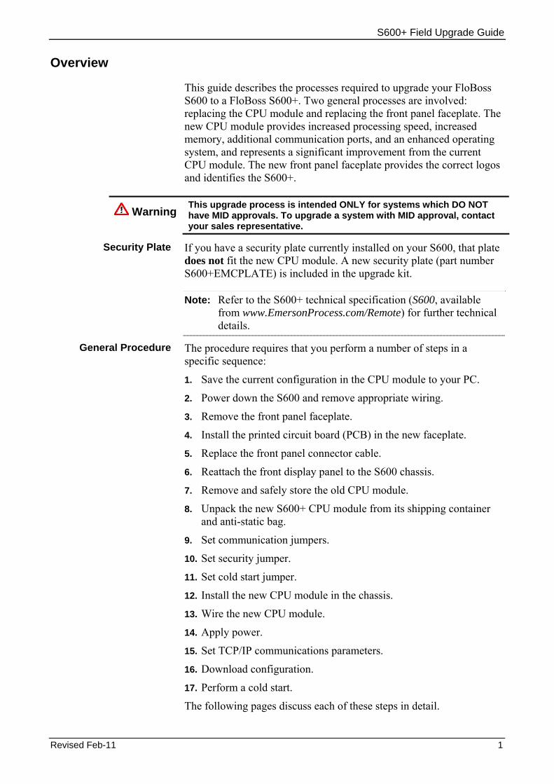
3. Remove the Front Panel Faceplate 1. Using a 2.5 mm Allen key, remove the hex cap screw from the
bottom centre of the front panel.
Figure 1. Removing the Hex Cap Screw
2 Revised Feb-11
S600+ Field Upgrade Guide
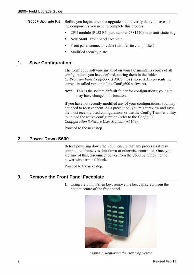
Note: A security cap may cover this hex screw.
2. Carefully slide the front panel up 4 mm to allow it to clear the retaining groove at the top of the case, and then allow the panel to come forward to clear the case completely.
Figure 2. Lifted Front Panel
3. Disconnect the ribbon cable from the back of the front panel at the blue connector.
Disconnect Here
Figure 3. Ribbon Cable
Proceed to the next step.
4. Install the Printed Circuit Board (PCB) 1. Place the front panel faceplate button-side down on a flat surface.
2. Remove the eight screws that secure the printed circuit board (PCB) to the faceplate (see Figure 4).
Revised Feb-11 3

S600+ Field Upgrade Guide
Screw Screw
Screws
Screws
Figure 4. Securing Screws
3. Lift the PCB from the old faceplate and place the PCB in the new faceplate.
4. Replace and secure the two top-most screws and the two bottom-most screws (see Figure 4).
5. Replace and gently tighten the four central screws.
Caution Do not over-tighten the four central screws. This can cause the rubber keypad to bind and affect the functioning of the S600+.
Proceed to the next step.
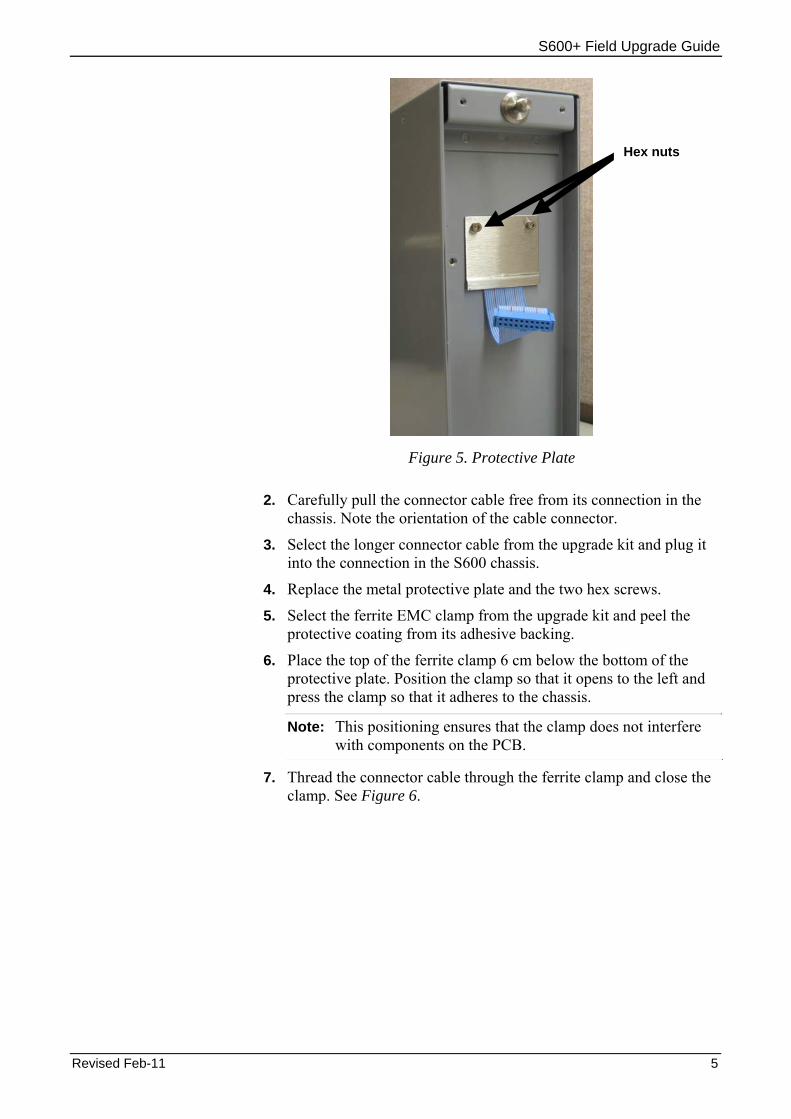
5. Replace the Front Panel Connector Cable 1. Unscrew the two hex screws on the metal panel protecting the
connector cable (see Figure 5) and remove the metal plate.
4 Revised Feb-11
S600+ Field Upgrade Guide
Hex nuts
Figure 5. Protective Plate
2. Carefully pull the connector cable free from its connection in the chassis. Note the orientation of the cable connector.
3. Select the longer connector cable from the upgrade kit and plug it into the connection in the S600 chassis.
4. Replace the metal protective plate and the two hex screws.
5. Select the ferrite EMC clamp from the upgrade kit and peel the protective coating from its adhesive backing.
6. Place the top of the ferrite clamp 6 cm below the bottom of the protective plate. Position the clamp so that it opens to the left and press the clamp so that it adheres to the chassis.
Note: This positioning ensures that the clamp does not interfere with components on the PCB.
7. Thread the connector cable through the ferrite clamp and close the clamp. See Figure 6.
Revised Feb-11 5

S600+ Field Upgrade Guide
Figure 6. Installed Ferrite Clamp
Proceed to the next step.
6. Reattach the Front Panel 1. Connect the ribbon cable to the front panel.
Caution Note how the connector fits into the keyway. You must insert the ribbon cable correctly. Do not force the connector into the keyway.
2. Place the top of the front panel over the retaining groove on the top boss and slide the front panel downwards.
3. Secure the front panel by placing the hex cap screw into its recess in the bottom centre of the front panel.
4. Using a 2.5 mm Allen key, tighten the screw finger-tight. Turn an additional 180 degrees to complete the installation.
Caution Do not over-tighten the screw. Over-tightening will damage the panel face.
Note: If a cap protected the hex screw, replace the cap.
Proceed to the next step.
6 Revised Feb-11

S600+ Field Upgrade Guide
7. Remove Current CPU Module Before you can remove the current CPU module, you may have to open the case for the S600. Depending on how the S600 is installed at your site, you may first have to remove a security plate that prevents easy access to the modules.
1. Disconnect all wiring to the CPU and any other installed modules.
Note: The power wiring to the new CPU module is identical to the old CPU module. However, other wiring is very similar. TB2 on the old CPU module has 13 pins. Pin 13 is not supported. Pins 5-13 are a single 5-pin connector block. If you use these, swap this 5-pin connector for a 4-pin connector. Detail the current wiring structure so you can replicate it with the new CPU module.
2. Remove the aluminium security plate at the back of the S600 chassis.
Note: Removing this plate may require you to detach wire seals placed in accordance with measurement requirements (such as NMi). Ensure that you follow the appropriate procedures to replace these seals.
3. Unscrew the retaining screws and remove the cover plate at the back of the CPU module.
4. Using the attached lifters, detach and slide the CPU module out of the chassis. Store it in an anti-static bag for safekeeping.
Proceed to the next step.
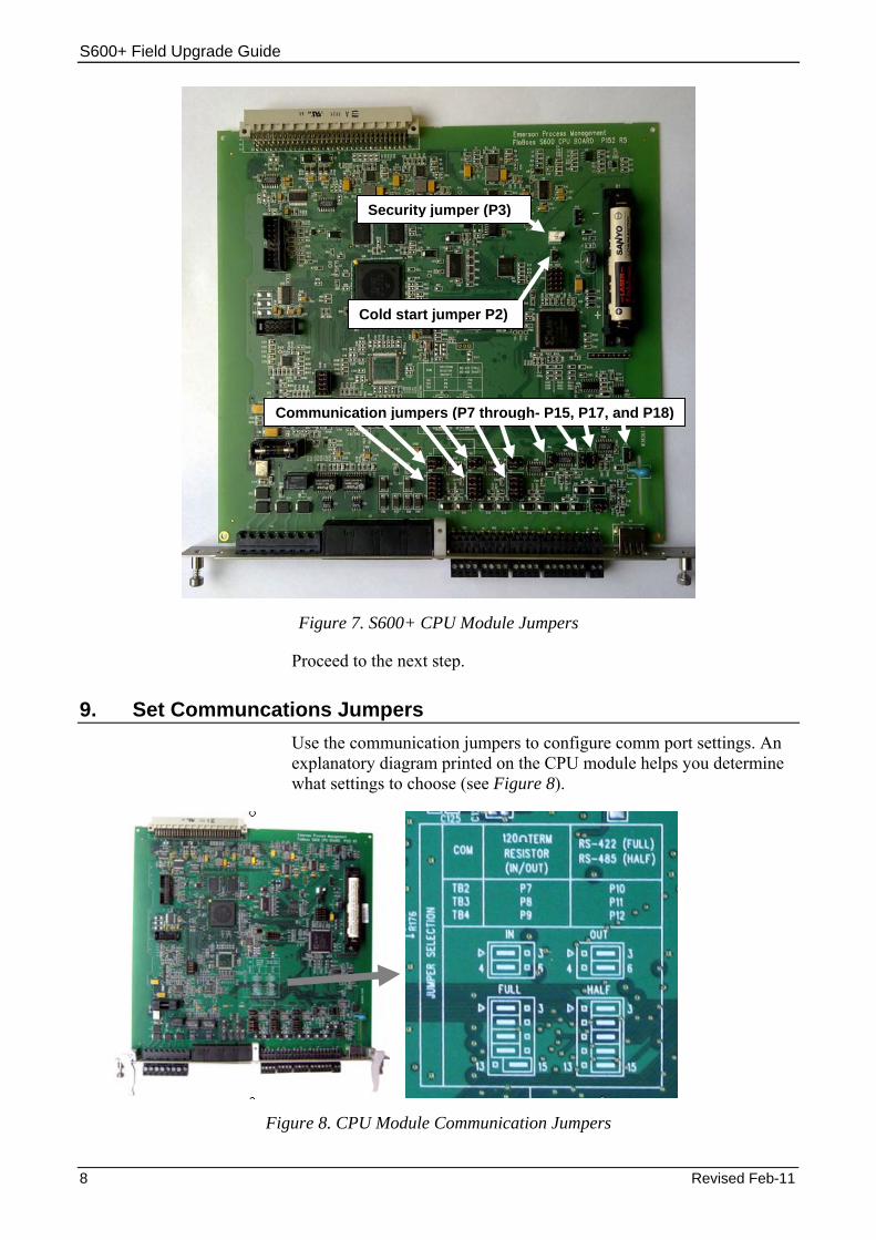
8. Unpack New CPU Module The new S600+ CPU module (P152 Rev 5 or above) is factory-packed in an anti-static bag. Carefully remove it from the bag, observing all cautions—including personal grounding—to prevent accidental static discharge (which might damage the CPU module). Place the module flat on a static-safe surface so that the communication connectors face up, as shown in Figure 7:
Revised Feb-11 7
S600+ Field Upgrade Guide
Security jumper (P3)
Cold start jumper P2)
Communication jumpers (P7 through- P15, P17, and P18)
Figure 7. S600+ CPU Module Jumpers
Proceed to the next step.
9. Set Communcations Jumpers Use the communication jumpers to configure comm port settings. An explanatory diagram printed on the CPU module helps you determine what settings to choose (see Figure 8).
Figure 8. CPU Module Communication Jumpers
8 Revised Feb-11

S600+ Field Upgrade Guide
Jumpers P10, P11, and P12 set the communication mode (RS-422 or RS-485). Jumpers P7, P8, and P9 provide the termination resistor required for RS-422 or RS-485 communications.
Comm 5 (TB2) Jumpers P7 and P10 work together.
Mode:
For RS-422 (full) mode, place the top four jumpers on P10 onto the left-most pair of pins.
For RS-485 (half) mode, place the top four jumpers on P10 onto the right-most pair of pins.
Note: The bottom jumper on P10 must always be on the right-most pair of pins.
Termination:
To enable termination, place the two jumpers on P7 onto the left-most pair of pins (1-2).
To disable termination, place the two jumpers on P7 onto the right-most pair of pins (2-3).
Comm 6 (TB3) Jumpers P8 and P11 work together.
Mode:
For RS-422 (full) mode, place the top four jumpers on P11 onto the left-most pair of pins.
For RS-485 (half) mode, place the top four jumpers on P11 onto the right-most pair of pins.
Note: The bottom jumper on P11 must always be on the right-most pair of pins.
Termination:
To enable termination, place the two jumpers on P8 onto the left-most pair of pins.
To disable termination, place the two jumpers on P8 onto the right-most pair of pins.
Comm 7 (TB4) Jumpers P9 and P12 work together.
Mode:
For RS-422 (full) mode, place the top four jumpers on P12 onto the left-most pair of pins.
For RS-485 (half) mode, place the top four jumpers on P12 onto the right-most pair of pins.
Note: The bottom jumper of P12 must always be on the right-most pair of pins.
Termination:
To enable termination, place the two jumpers on P8 onto the left-most pair of pins.
Revised Feb-11 9

S600+ Field Upgrade Guide
To disable termination, place the two jumpers on P9 onto the right-most pair of pins.
Comm 9 (TB5) Jumper P14 manages pins 1 and 2 of Comm 9 (TB5). RS-485 mode is always active for Comm 9. Place jumpers on the lowermost pair of pins to enable termination, or the uppermost pair of pins to disable termination.
Comm 10 (TB5) Jumper P13 manages pins 3 and 4 of Comm 10 (TB5). RS-485 mode is always active for Comm 10. Place jumpers on the lowermost pair of pins to enable termination, or the uppermost pair of pins to disable termination.
Comm 11 (TB5) Jumper P18 manages pins 1 and 2 of Comm 11 (TB5). RS-485 mode is always active for Comm 11. Place jumpers on the lowermost pair of pins to enable termination or the uppermost pair of pins to disable termination.
Comm 12 (TB6) Jumper P15 manages pins 1 and 2 of Comm 12 (TB6). It is active only if you select RS-485 mode for Comm 12. Place jumpers on the lowermost pair of pins to enable termination, or the uppermost pair of pins to disable termination.
Jumper P17(TB6)
Jumper P17 sets the functionality of TB6, enabling it to act either as an RS-485 comm port or a digital input port. Place jumpers on the leftmost upper and lower set of pins to activate RS-485 mode. Place the jumpers on the rightmost upper and lower set of pins to enable TB6 to act as a digital input port.
Note: This is new functionality with the S600+ CPU module.
Proceed to the next step.
10. Set Security Jumper Jumper P3 (see Figure 7) enables or disables system security. When the CPU module is delivered from the factory, P3 does not contain a jumper. This disables system security, and requires you to supply a password to change S600+ settings. Install a jumper on P3 to enable this security feature.
Proceed to the next step.
11. Set Cold Start Jumper Jumper P2 (see Figure 7) enables automatic warm start. As delivered from the factory, P2 does not contain a jumper. Place a jumper on P2 to disable automatic warm start, allowing you to bypass the password needed to access the cold start menu.
Proceed to the next step.
10 Revised Feb-11
S600+ Field Upgrade Guide
12. Install New CPU Module Once you have set all jumpers, slide the CPU module into the S600 chassis, ensuring that the module fits between the metal glides. Press the module firmly to secure the module’s connector to the backplane, and tighten the retaining screws.
Security Plate? The old security plate does not fit the new CPU module. Use the security plate included in the upgrade kit. Follow any site-required processes to re-attach wire seals. Proceed to the next step.
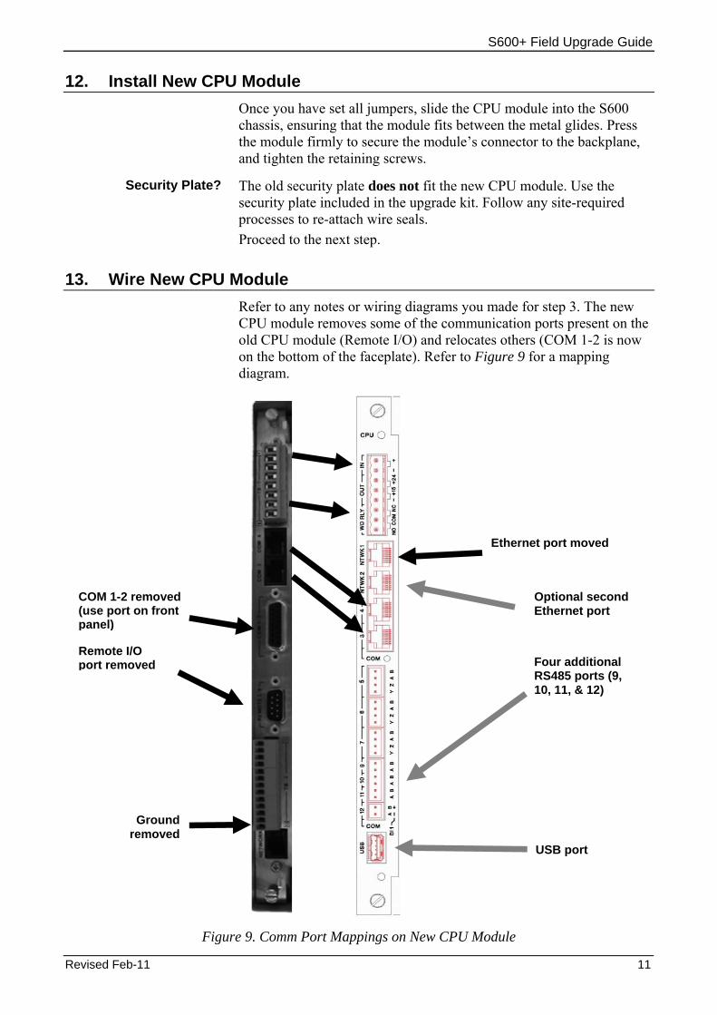
13. Wire New CPU Module Refer to any notes or wiring diagrams you made for step 3. The new CPU module removes some of the communication ports present on the old CPU module (Remote I/O) and relocates others (COM 1-2 is now on the bottom of the faceplate). Refer to Figure 9 for a mapping diagram.
Ethernet port moved
Optional second Ethernet port
COM 1-2 removed (use port on front panel)
Remote I/O port removed Four additional
RS485 ports (9, 10, 11, & 12)
Ground removed
USB port
Figure 9. Comm Port Mappings on New CPU Module
Revised Feb-11 11
S600+ Field Upgrade Guide
Note: Typically the ground tag “shield of wire” from the communications cable connects to ground at only one point. This may be the field end, or within the cubicle to a ground, or very rarely to the S600 itself. The previous CPU module provided a 13th pin (the last pin after Comm 7) for this purpose. If you need to ground the communications cable on the S600, you can use any ground tag. If you want to specifically connect to the CPU module, use the final communications port (the A connector on comm port 12), which you must define as a digital input. This process takes the very last pin direct to ground, and mimics the original CPU.
14. Apply Power As mentioned in step 6 and shown in Figure 7, the power connector remains unchanged between the old and new CPU modules. However, ensure that you have completed all other wiring before you apply power to the new CPU module.
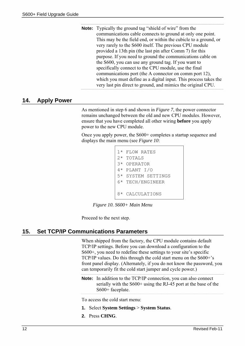
Once you apply power, the S600+ completes a startup sequence and displays the main menu (see Figure 10:
1* FLOW RATES 2* TOTALS 3* OPERATOR 4* PLANT I/O 5* SYSTEM SETTINGS 6* TECH/ENGINEER 8* CALCULATIONS
Figure 10. S600+ Main Menu
Proceed to the next step.
15. Set TCP/IP Communications Parameters When shipped from the factory, the CPU module contains default TCP/IP settings. Before you can download a configuration to the S600+, you need to redefine these settings to your site’s specific TCP/IP values. Do this through the cold start menu on the S600+’s front panel display. (Alternately, if you do not know the password, you can temporarily fit the cold start jumper and cycle power.)
Note: In addition to the TCP/IP connection, you can also connect serially with the S600+ using the RJ-45 port at the base of the S600+ faceplate.
To access the cold start menu:
1. Select System Settings > System Status.
2. Press CHNG.
12 Revised Feb-11

S600+ Field Upgrade Guide
3. Enter the default access code (1111).
Note: Change this default value to your site’s chosen value as soon as possible to prevent unauthorised access to the system.
4. Select Cold St and confirm your selection. The system restarts and displays the Cold Start menu:
1* WARM START 2* COLD START 3* NETWORK SETUP 4. REFLASH FIRMWARE 5. CONFIG SELECTION 8* FACTORY SETUP
Figure 11. Cold Start Menu
5. Select Network Setup.> Network I/F 1. The TCP/IP Menu displays (see Figure 12).
Note: Ensure that your Ethernet cable is connected into the NTWK1 port on the CPU module.
1. TCP/IP ADDRESS 1 2. GATEWAY ADDRESS 1 3. SUBNET MASK 1 4. TCP/IP MODE 5. GO BACK
Figure 12. TCP/IP Menu
6. Select TCP/IP Address 1, provide a valid TCP/IP address, and press the enter key (located at the lower right corner of the keypad).
7. Repeat the process to define a valid gateway address and a valid subnet mask.
8. Select Go Back > Go Back to return to the Cold Start menu.
Proceed to the next step.
16. Download Configuration Once you have configured communications, load one or more configurations to your S600+ using the Config Transfer utility.
Revised Feb-11 13

S600+ Field Upgrade Guide
Note: Only version 3.0 (and greater) of Config600 supports the enhanced functionality of the new CPU module.
1. Start Config600.
2. Select Tools > Transfer from the PCSetup main menu. The Config Transfer screen displays (see Figure 13).
Figure 13. Config Transfer Screen
3. On the Transfer tab, verify that the TCP/IP address in the Hostname field corresponds to the TCP/IP address you assigned the S600+.
4. Select the Send tab and select a configuration to download to the S600+.
5. Click Send. A Select Target Folder dialog displays.
Note: The S600+ can store up to 20 configurations, and automatically sets the last configuration downloaded as the default configuration. Use the Config Selector option on the Cold Start menu to select a different default configuration.
6. Highlight the target folder (“slot”) for this configuration. Press ▼ to display a sequence of all available slots.
Note: The S600+ lists any configurations already loaded.
7. Click OK. The utility displays a dialog monitoring the transfer.
Figure 14. Transfer Monitor
14 Revised Feb-11

S600+ Field Upgrade Guide
When the message Transfer completed successfully displays in this dialog, the process has finished.
8. Click OK to close the dialog and redisplay the Config Transfer Send tab.
9. You can download additional configs (repeating steps 4-8) or click Quit to exit the utility.
Proceed to the next step.
17. Cold Start the S600+ The final step is to complete the cold start for your S600+ (the Cold Start menu [see Figure 11] should still be displayed on your S600+).
Select Cold Start > Reset Totals. The S600+ restarts and displays the main menu associated with your selected configuration. .
This completes the process of upgrading your S600+.
Revised Feb-11 15

S600+ Field Upgrade Guide
16 Revised Feb-11
[This page is intentionally left blank.]