flipflops and excitation tables of flipflops
DESCRIPTION
Flipflops and Excitation tables of flipflopsTRANSCRIPT

Latches and flip-flops

Gates and flip-flops
Gates are the building block of the logic circuits. Their primary function is to perform decision making operations.
Flip-flops are the building blocks of the digital circuits. Their primary function is to store the binary bits.

Logic circuits are classified into two groups:
Combinational logic circuits
Sequential logic circuits
Basic buildingblocks include:
Basic building blocksinclude FLIP-FLOPS:
LOGIC CIRCUITS
Logic gates make decisions
Flip Flops have memory

Synchronous and Asynchronous Sequential Logic:-Synchronous – the timing of all state transitions is controlled
by a common clock – changes in all variables occur simultaneouslyAsynchronous – state transitions occur independently of any
clock and normally dependent on the timing of transitions in the input variables
– changes in more than one output do not necessarily occur simultaneously

Clock:- A clock is a special device that whose output
continuously alternates between 0 and 1.The time it takes the clock to change from 1 to
0 and back to 1 is called the clock period, or clock cycle time.
The clock frequency is the inverse of the clock period. The unit of measurement for frequency is the hertz.
Clocks are often used to synchronize circuits.
clock period

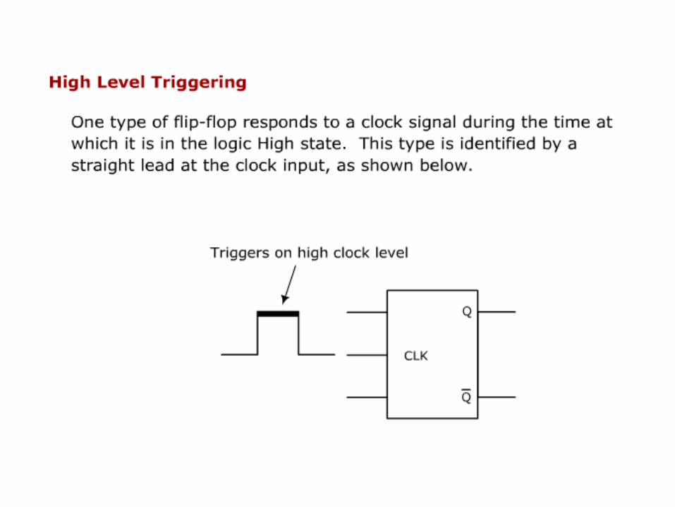
Triggering Sequential circuits are dependant on clock pulses
applies to their inputs. The result of flip-flop responding to a clock input is
called clock pulse triggering, of which there are four types. Each type responds to a clock pulse in one of four ways :-
1. High level triggering
2. Low level triggering
3. Positive edge triggering
4. Negative edge triggering


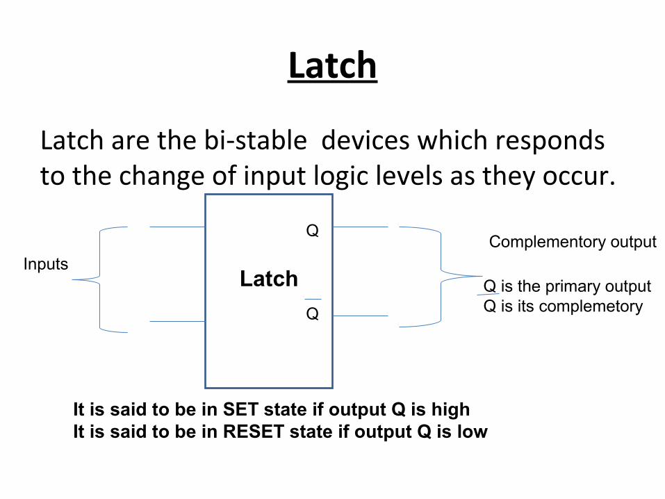
Latch
Latch are the bi-stable devices which responds to the change of input logic levels as they occur.
LatchInputs
Complementory outputQ
Q
Q is the primary outputQ is its complemetory
It is said to be in SET state if output Q is highIt is said to be in RESET state if output Q is low

R-S Latch using NOR gate
The two inputs, S and R denote ``set'' and ``reset'' respectively.
The latch has memory, and the present output is dependent on the state of the latch
R S Q Q comment
0 0 Qn Qn Previous state
0 1 1 0 SET state
1 0 0 1 RESET state
1 1 Not defined
Not defined
Not defined

R-S Latch using NAND gate
R S Q Q comment
1 1 Qn Qn Previous state
0 1 1 0 SET state
1 0 0 1 RESET state
0 0 Not defined
Not defined
Not defined
RQ
Q’S

Level-Sensitive/ Gated RS-Latch• “Q” only changes when CLK is high (i.e. level-sensitive)• When CLK is high, behavior same as RS latch
1 0 01 0 11 1 01 1 1
E S R
No change01
Undefined
Q0 X X No change
Race condition
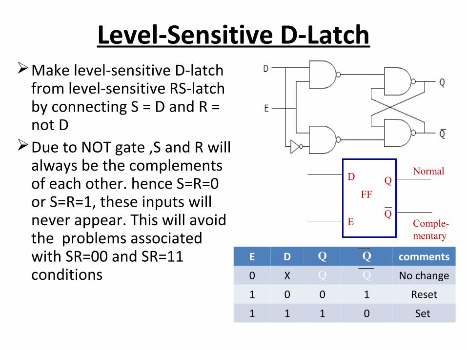
Level-Sensitive D-LatchMake level-sensitive D-latch
from level-sensitive RS-latch by connecting S = D and R = not D
Due to NOT gate ,S and R will always be the complements of each other. hence S=R=0 or S=R=1, these inputs will never appear. This will avoid the problems associated with SR=00 and SR=11 conditions
D
E
Q
Q
Normal
Comple-mentary
FF
E D Q Q comments
0 X Q Q No change
1 0 0 1 Reset
1 1 1 0 Set

CLOCKED R-S FLIP-FLOP
Set
Reset
S
R
Q
Q
FF
ASYNCHRONOUS
Outputs of logic circuit can change state anytime one or more input changes
Set
Reset
S
R
Q
Q
FF
ClockCLK
SYNCHRONOUS
Clock signal determines exact time at which any output can change state

Flip-flopsA flip-flop is a bi-stable device, with inputs,
that remains in a given state as long as power is applied and until input signals are applied to cause its output to change.
There are four basic different types of flip-flops:
SR D JK T

CLOCKED R-S FLIP-FLOPSymbols:
Truth Table:
Set
Reset
S
R
Q
Q
Normal
Comple-mentary
FF
ClockCLK
Clk S R Qn Qn
0 0 No change
0 1 0 1
1 0 1 0
1 1 Race Race
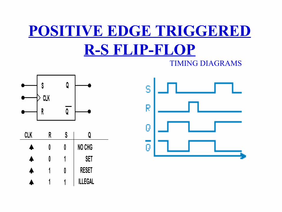
POSITIVE EDGE TRIGGEREDR-S FLIP-FLOP
TIMING DIAGRAMS
0
0
0 NO CHG
1
1 0
1 1
SET
RESET
ILLEGAL
CLK R S Q
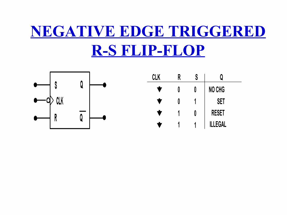
NEGATIVE EDGE TRIGGEREDR-S FLIP-FLOP
0
0
0 NO CHG
1
1 0
1 1
SET
RESET
ILLEGAL
CLK R S Q


D Flip-Flop
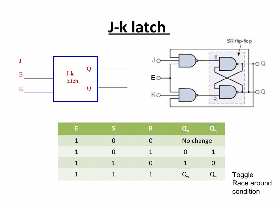
J-k latch
J
K
Q
Q
J-k latch
E
E S R Qn Qn
1 0 0 No change
1 0 1 0 1
1 1 0 1 0
1 1 1 Qn Qn ToggleRace around condition
Race around condition
This condition occur when j=k=1 i.e when the latch is in toggle mode.
This can be avoided by Using edge triggering J-k flip-flopUsing master slave flip-flop

J-K flip-flop
Clk J k Qn Qn
0 0 No change
0 1 0 1
1 0 1 0
1 1 Qn QnToggle
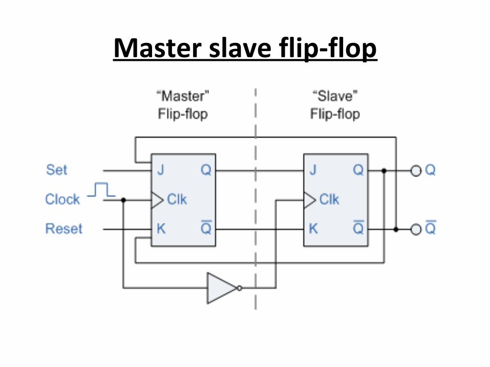
Master slave flip-flop

Master slave flip-flop
Clk j k Qn Qn
0 0 No change
0 1 0 1
1 0 1 0
1 1 Qn QnToggle

T flip flop
clk T Q Q comments
0 Q Q No change
1 Q Q toggle

Excitation tableSR flip-flop:-
Excitation table:-
Clk S R Qn Qn
0 0 No change
0 1 0 1
1 0 1 0
1 1 Race Race
Present state of Q o/p
Next state of Q o/p
Sn Input Rn input
0 0 0 ×
0 1 1 0
1 0 0 1
1 1 × 0

JK flip-flop:-
Excitation table:-Present state of
Q o/pNext state of Q
o/pJn Input Kn input
0 0 0 ×
0 1 1 ×
1 0 × 1
1 1 × 0
Clk J k Qn Qn
0 0 No change
0 1 0 1
1 0 1 0
1 1 Qn Qn

D flip-flop:-
Excitation table:-Present state of
Q o/pNext state of Q
o/pDn Input
0 0 0
0 1 1
1 0 0
1 1 1
Clk D Q
0 0
1 1
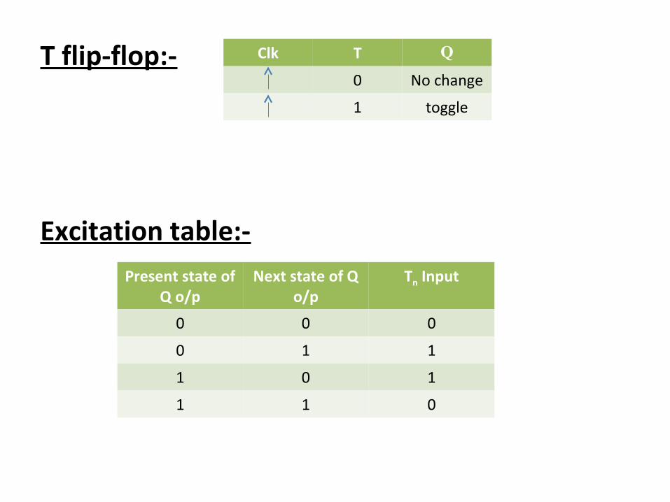
T flip-flop:-
Excitation table:-Present state of
Q o/pNext state of Q
o/pTn Input
0 0 0
0 1 1
1 0 1
1 1 0
Clk T Q
0 No change
1 toggle