flight-test-determined aerodynamic force and … · american institute of aeronautics and...
TRANSCRIPT

American Institute of Aeronautics and Astronautics
1
Flight-Test-Determined Aerodynamic Force and Moment Characteristics of the X-43A at Mach 7.0
Mark C. Davis*
NASA Dryden Flight Research Center, Edwards, California, 93523
and
J. Terry White† AS&M, NASA Dryden Flight Research Center, Edwards, California, 93523
The second flight of the Hyper-X program afforded a unique opportunity to determine the aerodynamic force and moment characteristics of an airframe-integrated scramjet-powered aircraft in hypersonic flight. These data were gathered via a repeated series of pitch, yaw, and roll doublets; frequency sweeps; and pushover–pullup maneuvers performed throughout the X-43A cowl-closed descent. Maneuvers were conducted at Mach numbers of 6.80 to 0.95 and altitudes from 92,000 ft msl to sea level. The dynamic pressure varied from 1300 psf to 400 psf with the angle of attack ranging from 0 deg to 14 deg. The flight-extracted aerodynamics were compared with preflight predictions based on wind-tunnel-test data. The X-43A flight-derived axial force was found to be 10 percent to 15 percent higher than prediction. Underpredictions of similar magnitude were observed for the normal force. For Mach numbers above 4.0, the flight-derived stability and control characteristics resulted in larger-than-predicted static margins, with the largest discrepancy approximately 5 in. forward along the x-axis center of gravity at Mach 6.0. This condition would result in less static margin in pitch. The predicted lateral–directional stability and control characteristics matched well with flight data when allowance was made for the high uncertainty in angle of sideslip.
Nomenclature ADSV = air data state vector AETB = Alumina-Enhanced Thermal Barrier AF = axial force, lbf AM = 6-DOF aerodynamic model alpha = angle of attack, deg ax, ay, az = IMU-measured acceleration components, ft/s2
BAS = body axis system BET = best estimated trajectory B.L. = butt line, in. CA = axial force, lbf CFD = computational fluid dynamics CG = center of gravity, ft CN = normal force, lbf CP = center of pressure, ft Cl = rolling moment, ft-lbf Cm = pitching moment, ft-lbf
* Aerospace Engineer, Research Engineering, NASA Dryden Flight Research Center, P.O. Box 273, M/S 2228, Edwards, California, 93523, Senior AIAA member. † Aerospace Engineer, AS&M, NASA Dryden Flight Research Center, P.O. Box 273, M/S 2228, Edwards, California, 93523, Senior AIAA member.
https://ntrs.nasa.gov/search.jsp?R=20070001000 2018-07-28T01:40:48+00:00Z

American Institute of Aeronautics and Astronautics
2
Cn = yawing moment, ft-lbf Cy = side force, lbf
DOF = degree-of-freedom dx, dy, dz = CG-to-nozzle moment arms, ft F = aerodynamic force, lbf FADS = flush air data sensing FHXRV = aerodynamic force reacting on the research vehicle, lbf FLT = flight-measured quantity, deg F.S. = fuselage station, in. Fwd = forward Fx, Fy, Fz = BAS aerodynamic force component, lbf g = gravitational constant, ft/s2 H = extraneous moment, ft-lbf HXLV = Hyper-X launch vehicle HXRV = Hyper-X research vehicle Hx, Hy, Hz = extraneous moment components, ft-lbf IMU = inertial measurement unit INS = inertial navigation system Ix, Iy, Iz = moments of inertia, lbf-s2-ft Ixy, Ixz, Iyz = products of inertia, lbf-s2-ft M = aerodynamic moment, ft-lbf MHXRV = moments reacting on the research vehicle, ft-lbf MS = maneuver sequence Mx, My, Mz = BAS aerodynamic moment components, ft-lbf m = vehicle mass, lbm msl = mean sea level NF = normal force, lbf PM = pitching moment, ft-lbf p = roll rate, rad/s
!p = roll acceleration, rad/s2
q = pitch rate, rad/s
!q = pitch acceleration, rad/s2
qbar = dynamic pressure, lbf/ft2 R = extraneous force, lbf RM = rolling moment, ft-lbf Rx, Ry, Rz = extraneous force components, lbf r = yaw rate, rad/s !r = yaw acceleration, rad/s S3I = sequential single surface inputs SF = side force, lbf scramjet = supersonic combustion ramjet T = thrust force, lbf Tx, Ty, Tz = thrust components, lbf UTC = coordinated universal time V = total velocity, ft/s W = weight force, lbf W.L. = water line, in. Wx, Wy, Wz = BAS weight component, lbf x, y, z = axis x , y , z = CG-to-accelerometer moment arms, ft YM = yawing moment, ft-lbf Subscripts Accel = acceleration

American Institute of Aeronautics and Astronautics
3
Nom = nominal Req = required Greek ! = angle of attack, deg ! = angle of sideslip, deg
! = deflection, deg !e = elevator deflection, deg Γ = thrust-induced moment, ft-lbf
I. Introduction HE X-43A, also known as the Hyper-X Research Vehicle (HXRV), is an experimental research aircraft designed to fly autonomously within the earth’s atmosphere at hypersonic speeds up to Mach 10. The X-43A is
powered by an airframe-integrated, hydrogen-fueled, dual-mode, supersonic combustion ramjet (scramjet) that is rocket-boosted to its hypersonic test point. The primary objective of the X-43A project was to successfully demonstrate the design tools and methodology of the scramjet engine at hypersonic flight conditions.1 Three X-43A vehicles were constructed to conduct three test flights of a single propulsion test point each. Flight 1 was to be tested at Mach 7, but was terminated because of a problem with the Pegasus® (Orbital Sciences Corporation, Dulles, Virginia, USA) air-launched booster rocket. Flight 2 was successfully tested at Mach 6.8, and flight 3 was successfully tested at Mach 9.6.2 In addition to the scramjet flight research, the X-43A flight project provided information that can be used to expand the hypersonic aerodynamic database.
Flight 2 of the X-43A successfully established and demonstrated supersonic combustion in the scramjet engine and produced sufficient thrust to accelerate the research vehicle. The nominal test conditions for the engine test were a speed of Mach 7 and an altitude of 95,000 ft msl. Over 1100 channels of data were recorded during the flight. Data included were flight kinematics based on inertial navigation system (INS), global positioning system (GPS), and radar assets; airframe external surface pressure and thermocouple data; HXRV accelerometer and rate gyroscope measurements; control surface positions; and strain gage readings. Reference 3 provides more information on the X-43A project along with the numerous technological areas that the flight test supported.
This report focuses on the aerodynamic force and moment characteristics of the HXRV during the descent portion of the flight test. These flight-extracted aerodynamic force and moment data were then compared to the X-43A preflight 6-degree-of-freedom (DOF) aerodynamic model to validate and update the latter.
II. Mission Description The flight test was comprised of four distinct phases, as identified in Fig. 1. Phase 1 was the captive carry to the
launch condition. Phase 2 included drop, booster ignition, and climb-out to the hypersonic test point (an altitude of 95,000 ft msl). During phase 2 the HXRV was riding on the first stage of the Pegasus air-launched booster rocket, referred to as the Hyper-X launch vehicle (HXLV). Phase 3 comprised the separation of the research vehicle from the Pegasus booster. Phase 4 was the scramjet operation and the cowl-closed descent portion of the flight. The data presented in this report were obtained during the cowl-closed descent segment of phase 4 only.
During the descent phase a series of maneuvers was flown comprised of an automated maneuver sequence (MS) designed to extract X-43A aerodynamic data from flight. Each MS sequence consisted of sequential single surface inputs (S3I), Schroeder sweeps, and pushover–pullup maneuvers. The cowl-closed MS series was repeated at every integer Mach number between 5 and 2, inclusive. Including the pre- and post-MS periods, six segments of the descent phase were analyzed.
The first segment of the descent phase was the pre-MS, which began just after the cowl was closed and ended at a speed of Mach 5. In the figures accompanying this report, the pre-MS begins at 0 s and ends at 115 s. The pre-MS was also known as the post-engine-test recovery maneuver, during which the X-43A performed a pushover maneuver to arrest the dynamic pressure buildup.
Maneuver sequence 1 began at a speed of Mach 5 and was the beginning of the S3I for the flight. Maneuver sequence 1 ended at a speed of Mach 4; in the figures accompanying this report, MS-1 begins at 115 s and ends at 190 s.
Maneuver sequence 2 began at a speed of Mach 4 and was the second S3I, ending at a speed of Mach 3. In the figures accompanying this report, MS-2 begins at 190 s and ends at 265 s.
T

American Institute of Aeronautics and Astronautics
4
Maneuver sequence 3 began at a speed of Mach 3 and ended at a speed of Mach 2. In the figures accompanying this report, MS-3 begins at 265 s and ends at 325 s.
Maneuver sequence 4 began at a speed of Mach 2.0, contained the last S3I of the flight, and ended at a speed of approximately Mach 1.4. In the figures accompanying this report, MS-4 begins at 325 s and ends at 390 s.
The post-MS segment began at a speed of approximately Mach 1.4 and ended at splashdown. In the figures accompanying this report, the post-MS begins at 390 s and ends at 470 s.
Table 1 shows the time line for each MS during the descent phase. Note that all flight maneuvers were performed with the airframe trimmed and that the flight control system limited normal acceleration to 2.5 g.
Table 1. Trajectory time segments.
Flight segment Start time, s Start Mach Start altitude, ft Start qbar, psf
Pre-MS 0.00 6.81 89832 1187.08
MS-1 112.16 5.02 86288 759.68
MS-2 192.17 4.00 76077 782.22
MS-3 262.62 3.00 67420 672.68 MS-4 327.65 2.00 61405 402.33
Post-MS 390.00 1.40 43627 480.12
Data stop 469.53 0.91 38 1245.60
Zero time = 14:02:09.5796 UTC
III. Flight Vehicle Description Figure 2 illustrates the HXRV external configuration. The vehicle is 12 ft long, 5 ft wide, and 2.2 ft tall, with a
maximum weight of 2800 lbf. Figure 2 also depicts the airframe-integrated nature of the HXRV scramjet engine installation. In Fig. 2, the light-colored portion of the nose is tungsten, the light-colored portions of the wing and tail are comprised of Haynes alloy (a high-temperature, high-strength metal) (Haynes International, Inc., Kokomo, Indiana, USA), and the leading edges of the nose and wings are protected by reinforced carbon/carbon leading edges. The black surfaces of the vehicle are composed of Alumina-Enhanced Thermal Barrier (AETB) (The Boeing Company, Chicago, Illinois, USA) thermal protection material. The lower protrusion shown on the vehicle front view and side view is the experimental scramjet engine, which is made of copper. Note that the lower aft-body functions as the propulsion system expansion nozzle. Figure 3 shows the vehicle being prepared for flight. Orange foam covers labeled “DO NOT TOUCH” protect the delicate carbon/carbon leading edges that in turn protect the X-43A nose and wing from the high heat loads experienced during the mission.
IV. Aerodynamic Force and Moment Extraction Methodology Extraction of the HXRV cowl-closed aerodynamics from flight data is based on manipulation of the body axis
system (BAS) 6-DOF equations of motion. Flight-measured kinematic state measurements, onboard accelerometer and rate gyroscope readings, and mass property model data are used to calculate BAS 6-DOF aerodynamic forces and moments. The BAS referred to here is defined in Fig. 4. Figure 5 defines the HXRV design coordinate system, which is provided for reference because the HXRV center of gravity (CG) position is expressed in terms of that coordinate system.
A. Aerodynamic Overview Analysis of the 6-DOF aerodynamics of the HXRV was a three-step process that included: (1) extraction of the
HXRV aerodynamic forces and moments from flight data, (2) using flight conditions as inputs to the HXRV aerodynamic model, and (3) comparison of these aerodynamic model predictions with flight data. In step (3) flight-versus-prediction discrepancies were identified and remedial actions were formulated. The actions could involve changing the pitching moment magnitude or elevator schedule of the X-43A vehicle, for example. Figure 6 provides an overview of the pitching moment matching schemes.

American Institute of Aeronautics and Astronautics
5
The extraction of the aerodynamic forces and moments from the flight data required four elements. The first required element was the trajectory kinematics. The second required element was the launch-day meteorology. For this project, a best estimated trajectory (BET) was developed. The BET was used to estimate the true state including Mach number, dynamic pressure, angle of attack, and angle of sideslip. The third required element utilized the measured IMU accelerations and body rates. The fourth required element utilized the airframe mass properties including airframe mass, three-axis CG location, three-axis moments of inertia, and products of inertia.
Four elements were required to run the HXRV aerodynamic models at flight conditions. The first element was the trajectory kinematics. The second element was the measured aerodynamic attitudes. The third element was the control surface deflections as measured during flight. The fourth element was the mass properties for the vehicle.
V. Data Processing Methodology All data used in the current analysis required some form of pretreatment prior to application of the force and
moment extraction methodology. Since not all of the necessary parameters were sampled at the same rate, the data had to be time-synchronized and normalized to a rate of 100Hz. Telemetry glitches such as dropouts or spurious data hits were accounted for during this process. A third-order Butterworth filter was utilized to filter and smooth the data prior to the application of a sixth-order central difference scheme employed to compute the required time derivatives. Finally, airframe mass properties inclusive of vehicle mass, three-axis CG position, three-axis moments of inertia, and the products of inertia were based on the HXRV pre flight mass properties model.
A. 3-σ Aerodynamic Uncertainties Flight simulation and control law development analysis require an aerodynamics database, which, prior to a
vehicle’s first flight, is typically based on wind-tunnel-test-data. Considering the database tables used to represent the nominal aerodynamics of the flight vehicle, uncertainties must be included in the supporting analysis to allow for the design of robust flight systems. Wind-tunnel data uncertainty is, however, only one factor that must be taken into account in the quest for robustness. There are also uncertainties associated with the synthesis of the aerodynamic model from wind-tunnel data and uncertainties associated with how accurately the resulting aerodynamic model characterizes the actual flight vehicle aerodynamics. In fact, experience shows that this latter category often accounts for the most significant level of uncertainty as described in references 4–6.
Uncertainties were computed at the 3-σ level for both the HXRV flight-derived and aerodynamic-model-predicted 6-DOF aerodynamic forces and moments. The method used to estimate these uncertainties is presented in Refs. 7 and 8. Reference 7 outlines the Space Shuttle aerodynamic uncertainties, which were considered the sum of wind-tunnel-testing uncertainties and wind-tunnel-to-flight uncertainties. The former were referred to as tolerances and the latter as variations. An extensive wind-tunnel database was obtained during the Space Shuttle engineering development program using a large array of wind-tunnel models, which were tested in a variety of wind-tunnel test facilities. Tolerances account for the experimental uncertainty attributed to model-to-model and tunnel-to-tunnel flow differences. Variations account for the deviations observed between preflight predictions and flight-test data for a number of aircraft with preflight aerodynamic predictions. Notable in this regard is the historical survey of Weil and Powers reported in Ref. 9. The X-43A preflight aerodynamic uncertainties model is patterned after the method of this report. These uncertainties are shown for comparison purposes with the flight-versus-prediction discrepancies in the next several sections of this report. Generally, the aerodynamic model uncertainties are larger than the corresponding flight-derived values. The reasons for this are twofold. First, the aerodynamic model uncertainties are quite conservative in keeping with the first-flight nature of the associated uncertainties model. The three primary contributors to this uncertainties model are (1) wind tunnel–computational fluid dynamics (CFD) data uncertainty, (2) wind tunnel–CFD data-to-aerodynamic model uncertainties, and (3) aerodynamic model-to-flight uncertainties. For a first flight, the third factor is traditionally the largest contribution to the total uncertainty and such was the case for the Hyper-X first flight. This third factor is amplified in the fact that there are no similar vehicles with which to compare. Second, the uncertainties associated with the flight-derived aerodynamics are typically small since flight measurement uncertainties are generally small and well-defined.
VI. HXRV Forces and Moments The algorithms and formulas described in this report are applicable to all phases of X-43A flight. The sum of the
forces operative on the HXRV during flight is expressed in vector form in Eq. (1):
!FHXRV! =
!F +!T +!R +!W (1)

American Institute of Aeronautics and Astronautics
6
The vectored quantities F, T, R, and W are, respectively, the aerodynamic, thrust, extraneous, and weight forces.
Likewise, the sum of the moments operative about the HXRV CG during flight is expressed in vector form in Eq. (2):
!MHXRV! =
!M +
!" +
!H (2)
The vectored quantities M, Γ, and H are, respectively, the aerodynamic, thrust-induced, and extraneous moments. Note that the term extraneous simply means unmodeled or unaccounted-for forces or moments, regardless of whether they are aerodynamic, propulsive, or weight-related in nature.
A. Force and Moment Algorithm The BAS aerodynamic forces were extracted from the HXRV IMU accelerometer package measurements by
first computing the absolute translational acceleration operative at the HXRV CG per Ref. 10 as shown in Eq. (3):
ax
ay
az
!
"
###
$
%
&&&CG
=
ax
ay
az
!
"
###
$
%
&&&IMU
'
' q2+ r
2( )x + pq ' !r( )y + pr + !q( ) z
pq + !r( )x ' p2+ r
2( )y + qr ' !p( ) z
pr ' !q( )x + qr + !p( )y ' p2+ q
2( ) z
!
"
#####
$
%
&&&&&
(3)
In the above, the second matrix on the right-hand side represents the ensemble of linear components of the HXRV rotational (tangential and centripetal) accelerations, which must be subtracted from the IMU accelerometer outputs to arrive at the true translational acceleration. The CG-to-accelerometer package moment arms are defined in Eq. (4):
x
y
z
!
"
###
$
%
&&&
=
CGx ' Accelx
CGy ' Accely
CGz ' Accelz
!
"
###
$
%
&&&
(4)
It is important to note that the corrected IMU acceleration outputs represent the difference between the vehicle absolute acceleration impressed along a given BAS channel and the component of weight acting along that same channel. Mathematically, this is expressed in Eq. (5) as:
ax
ay
az
!
"
###
$
%
&&&CG
= 1
m
Fx + Tx + Rx +Wx
Fy + Ty + Ry +Wy
Fz + Tz + Rz +Wz
!
"
###
$
%
&&&
' 1
m
Wx
Wy
Wz
!
"
###
$
%
&&&
= 1
m
Fx + Tx + Rx
Fy + Ty + Ry
Fz + Tz + Rz
!
"
###
$
%
&&&
(5)
The subscripted variables F, T, R, and W are, respectively, the aerodynamic, propulsive, extraneous force, and
weight force components acting along a given BAS axis. Solving for the BAS aerodynamic forces, substituting Eq. (5) into Eq. (3) provides us with Eq. (6):

American Institute of Aeronautics and Astronautics
7
Fx
Fy
Fz
!
"
###
$
%
&&&CG
= m
ax
ay
az
!
"
###
$
%
&&&IMU
' m
' q2+ r
2( )x + pq ' !r( )y + pr + !q( ) z
pq + !r( )x ' p2+ r
2( )y + qr ' !p( ) z
pr ' !q( )x + qr + !p( )y ' p2+ q
2( ) z
!
"
#####
$
%
&&&&&
'
Tx
Ty
Tz
!
"
###
$
%
&&&
'
Rx
Ry
Rz
!
"
###
$
%
&&&
(6)
Accounting for the sign differences between the BAS aerodynamic forces and the aerodynamic axial and normal
forces yields Eq. (7):
AF
SF
NF
!
"
###
$
%
&&&
=
'FxFy
'Fz
!
"
###
$
%
&&&
(7)
The aerodynamic moments taken about the HXRV CG location were extracted from flight data by manipulation of the Ref. 10 BAS moment equations shown in Eq. (8):
Mx!
My!
Mz!
"
#
$$$$
%
&
''''CG
=
!pIx + qr(Iz ( Iy ) + (r2 ( q2
)Iyz + (pr ( !q)Ixy ( (pq + !r)Ixz
!qIy + pr(Ix ( Iz ) + (p2 ( r2
)Ixz + (pq ( !r)Iyz ( (qr + !p)Ixy
!rIz + pq(Iy ( Ix ) + (q2 ( p2
)Ixy ( (pr ( !q)Iyz + (qr ( !p)Ixz
"
#
$$$$
%
&
''''
(8)
Equivalently, these moments can be expressed as the sum of aerodynamic, propulsive, and extraneous moment
contributors as shown below in Eq. (9):
Mx!
My!
Mz!
"
#
$$$
%
&
'''CG
=
Mx ( (Tydz ( Tzdy ) + Hx
My + (Txdz ( Tzdx ) + Hy
Mz ( (Txdy ( Tydx ) + Hz
"
#
$$$$
%
&
''''CG
(9)
The CG-to-scramjet nozzle moment arms are defined as in Eq. (10):
dx
dy
dz
!
"
###
$
%
&&&=
xCG ' xNozzle
yCG ' yNozzle
zCG ' zNozzle
!
"
###
$
%
&&&
(10)
Manipulation of the above yields the expressions shown in Eq. (11) for the BAS aerodynamic moments taken
with respect to the airframe CG location:

American Institute of Aeronautics and Astronautics
8
Mx
My
Mz
!
"
####
$
%
&&&&CG
=
!pIx + qr(Iz ' Iy ) + (r2 ' q2
)Iyz + (pr ' !q)Ixy ' (pq + !r)Ixz
!qIy + pr(Ix ' Iz ) + (p2 ' r2
)Ixz + (pq ' !r)Iyz ' (qr + !p)Ixy
!rIz + pq(Iy ' Ix ) + (q2 ' p2
)Ixy ' (pr ' !q)Iyz + (qr ' !p)Ixz
!
"
####
$
%
&&&&
'
' (Tydz ' Tzdy )
+ (Txdz ' Tzdx )
' (Txdy ' Tydx )
!
"
###
$
%
&&&
'
Hx
Hy
Hz
!
"
###
$
%
&&&
(11)
Solution of the BAS aerodynamic force and moment extraction equations requires using a combination of flight
measurements and preflight models. The onboard flight measurements include time histories of (1) three-axis translational accelerations, (2) three-axis rotational accelerations, (3) control surface deflections, (4) three-space inertial velocities, (5) geometric altitude, (6) Euler angles (that is, inertial roll, pitch, and heading angles), and (7) wind estimates. Items (4) and (6) permit calculation of the BAS velocity components and a corresponding calculation of HXRV aerodynamic attitude (that is, angle of attack and angle of sideslip).
VII. Discussion and Results Time histories of the Hyper-X flight 2 descent phase air data, aerodynamic attitude, and control deflections are
presented in appendix A. Identified on these time histories are the segments of flight corresponding to the MS described in the “Mission Description” section and table 1 above. Figures A-01 through A-05 show the comparisons of the postflight trajectory reconstruction to the INS flight data. Figure A-01 shows that the BET- and INS-based Mach numbers are generally within 1 percent of each other and that the BET value is typically the higher of the two. Figure A-02 shows that the BET and INS geometric altitudes also compare well with each other throughout the flight. Figure A-03 shows that the BET dynamic pressure is 2 percent to 4 percent higher than the INS-based data. The BET and INS angle-of-attack curves, shown in Fig. A-04, compare favorably through the end of MS-4. Beyond this point, differences of approximately of 1° are observed in the post-MS period for the angle-of-attack comparison. While the BET and INS angle-of-sideslip data shown in Fig. A-05 compare very well up to the end of MS-1, differences between the two appear and continue to grow thereafter. These differences in angle of sideslip are as large as 3° in the post-MS period. Figures A-06, A-07, and A-08 present the flight data for elevator, rudder, and aileron controls, respectively.
A. Flight-Extracted Longitudinal Aerodynamics The HXRV flight-extracted longitudinal aerodynamics (that is, BAS axial force, normal force, and pitching
moment) are presented in appendix B. Also included are the results from running the HXRV 6-DOF aerodynamic model at flight conditions. The purpose of running this model was to evaluate how accurately the HXRV cowl-closed aerodynamic forces and moments were replicated by the aerodynamic model. Note that the aerodynamic model results were generated using flight conditions from both the BET and INS data sets. This approach provided an approximate means for determining the effects of atmospheric winds on flight-extracted aerodynamic forces and moments.
B. Body Axis System Axial Force Figures B-01 through B-04 pertain to the flight-extracted BAS axial force during the HXRV descent phase of the
flight. Figure B-01 shows that the modeled data are always less than the flight results, with the BET-based data closer to the flight data than are the INS-based values. Figure B-02 shows that the disparity between the BET-based axial force prediction and flight during the MS maneuver period is essentially consistent. This includes that part of the descent phase starting at a speed of Mach 5.0 and proceeding down through a speed of approximately Mach 1.5. The modeled data difference observed during the pre- and post-MS flight segments is noticeably larger than that of the MS segments. The pre-MS period (0 s to 115 s) exhibits relatively small differences compared with the prediction. Much larger differentials are seen in the post-MS period (390 s to approximately 470 s). These axial force differentials are largely the result of inherent differences that exist between subscale ground testing and fullscale flight. Key areas of consideration include (1) wind-tunnel replication of flight-scale flow phenomena such

American Institute of Aeronautics and Astronautics
9
as skin friction and flow separation, (2) wind-tunnel-model fidelity, and (3) wind-tunnel-data corrections associated with model support mechanism influences.
Perhaps the largest contributor to the axial force discrepancies is wind-tunnel-model fidelity. First, the wind-tunnel-model cowl-closed scramjet installation was modeled as a solid block with sealed inlet and exit planes. This configuration was in contrast with the full-scale flight vehicle which had (1) an exit plane open to the interior of the engine, and (2) a small slit between the top of the closed cowl door and the scramjet inlet. As verified by flight-measured internal pressures, this latter feature permitted extraneous flow through the scramjet engine even in the cowl-closed configuration. Flow though the flight-scale scramjet engine implies not only the existence of extraneous internal forces and moments, but modification of lower surface aerodynamics as well, the main effect being the modification of X-43A nozzle region aerodynamic forces and moments. These effects were not modeled in the wind tunnel. A consideration relative to wind-tunnel-model fidelity concerns the aerodynamic effects of fullscale vehicle protuberances not relocated on the wind-tunnel model. These protuberances include the boundary layer trip, surface roughness, thermal protection tiles, auxiliary gas outlets, and the like.
Figure B-03 expresses the axial force differential as a percentage of the flight value for the BET- and INS-based aerodynamic model air data sets. In this context, the axial force prediction is approximately 17 percent low near a speed of Mach 6.5, but steadily improves to approximately 8 percent low as the HXRV decelerated through a speed of Mach 4.0. Between a speed of Mach 4.0 and a speed of Mach 1.5 (190 s to approximately 400 s), the average prediction accuracy remains at approximately 8 percent lower than the flight value. Below a speed of Mach 1.5, the predictive accuracy rapidly degrades, exceeding 30 percent low.
Figure B-04 shows the axial force differentials relative to 3-σ uncertainties in the flight data and the aerodynamic model data. Except for briefly exceeding the uncertainty bounds in the post-MS segment, the axial force differentials lie within the 3-σ uncertainty bounds of the aerodynamic model. However, the axial force differential generally lies just at or beyond the flight data 3-σ uncertainty bounds.
C. Body Axis System Normal Force Figures B-05 through B-08 pertain to the flight-extracted BAS normal force during the HXRV descent phase of
the flight. Figure B-05 shows large differences in normal force during the pre- and post-MS for the descent. As observed in Fig. B-06, the aerodynamic-model-generated normal force (based on BET air data) is lower than flight through the end of MS-3. A large differential occurs at the beginning of the descent, decreasing as the HXRV decelerates through a speed of Mach 5. Between a speed of Mach 5 and a speed of Mach 2 (115 s to 325 s), the disparity continues to steadily decrease until it is virtually zero at the lower Mach numbers. Once below a speed of Mach 2, the predicted normal force rapidly exceeds the flight value through a speed of Mach 1. At the lower Mach numbers, the normal force differential grows large. Between a speed of Mach 1 and splashdown, the predicted normal force fluctuates around the nominal flight values. As is the case for axial force, the pre-MS normal force differentials are the result of inherent differences that exist between subscale ground testing and fullscale flight. The post-MS period is also affected by this as well as uncertainties in the magnitude and direction of atmospheric winds extant at the lower altitude and speeds encountered in this region of flight.
Figure B-07 presents the normal force differential as a percentage of the flight value. In the pre-MS flight segment, these results show that the predicted normal force is as much as 20 percent below the flight value. However, between a speed of Mach 5 and a speed of Mach 2 (115 s to 325 s), the differential varies from 11 percent to essentially 0 percent respectively. As pointed out previously, the predicted normal force exceeds the flight-measured value for most of the remainder of the flight. During MS-4, the maximum normal force is overpredicted by 13 percent while during the post-MS flight segment there is an overprediction on the order of 40 percent. Again, these normal force differentials are largely attributable to ground-testing-to-flight effects and uncertainty in the atmospheric state.
Figure B-08 shows the normal force differential relative to 3-σ uncertainties in the flight data and the preflight-predicted aerodynamic model data. Except for briefly exceeding the uncertainty bounds in the pre- and post-MS segments, the normal force differentials lie well within the 3-σ uncertainty bounds of the aerodynamic model. The normal force differential generally lies within the flight data 3-σ uncertainty bounds between a speed of Mach 4 and a speed of Mach 2 (190 s to 325 s). However, the differences before and after this period markedly exceed the flight 3-σ uncertainty bounds.
D. Body Axis System Pitching Moment Figure B-09 through B-11 pertain to the flight-extracted BAS pitching moment during the HXRV descent phase.
Figure B-09 shows the expected oscillation about a mean of zero, which is indicative of trimmed flight. The 6-DOF

American Institute of Aeronautics and Astronautics
10
aerodynamic model data show trimmed flight regardless of the air data source used. The predicted pitching moment has less static margin than flight above a speed of Mach 4 and more static margin below this Mach number. For this flight, the angle of attack was positive. In Fig. B-10, the pitching moment differential varies from unstable static margin to stable static margin. Figure B-11 shows that the pitching moment differential lies well outside both the flight and 6-DOF aerodynamic model 3-σ uncertainty bounds. The pitching moment results can be equivalently expressed in terms of the location of the longitudinal center of pressure (CP).
Figure B-12 presents the flight-derived CP location-time history for the HXRV descent phase. Note that the mean CP location occurs at the vehicle CG point. Since the HXRV flies at and performs all maneuvers from a trimmed condition, it is expected that the CP lies at the CG. For the pre-MS period, the HXRV performs a recovery maneuver flight profile until the start of MS-1. During the pre-MS period, the computed CP is coincident with the HXRV CG. Within the MS-1 period, small-amplitude CP oscillations occur about the CG as the vehicle responds to the high-frequency S3I and Schroeder sweep inputs. The amplitude of these CP oscillations typically occurs slightly fore and aft of the CG position. These oscillations are attributable to several factors. First, while the HXRV is highly controlled, there is always a small lag between the command to and response of the airframe. Therefore, during a maneuver transient, the instantaneous CP location will slightly lag the associated commanded control surface position. Second, the accuracy of the CP calculation is sensitive to the synchronization and accuracy of the flight-extracted normal force and pitching moment data. Synchronization effects become more of a problem in a transient environment. This helps account for the occasional spike-like departures in the CP location from the vehicle CG positions that are observed in the MS flight segment data. Both the larger oscillatory and spike-like CP migrations seen in the post-MS flight data are products of higher airframe dynamics attendant to execution of the airframe control task in transonic flight.
Figure B-13 presents the longitudinal CP time-history as predicted by the HXRV 6-DOF aerodynamic model. Note that airframe trim is generally not exhibited in these data. Figure B-14 shows the variation of the differential between the BET-based aerodynamic model data and flight CP during the descent phase. Above a speed of Mach 4, the predicted CP location is forward of the flight value, while the opposite trend is evident below a speed of Mach 4. In general, the CP differential is small during the MS series, however, larger deviations are exhibited during the pre- and post-MS flight segments.
E. Longitudinal Aerodynamics Discrepancy Resolution An extensive effort was made to account for the longitudinal aerodynamic force and moment discrepancies
observed between prediction and flight. This effort focused on finding a rational means for matching the preflight-predicted pitching moment with the flight equivalent. It was reasoned that a legitimate adjustment mechanism would have to provide also for simultaneous normal force and axial force matching. Three pitching moment matching schemes were considered. Scheme 1 assumes that the nominal flight angle of attack is correct and that the flight pitching moment can be matched through adjustment of elevator deflection. Scheme 2 assumes that the nominal elevator deflection is correct and that the flight pitching moment can be matched through adjustment of angle of attack. Scheme 3 is a hybrid method predicated on the premise that the flight pitching moment can be matched via a unique combination of elevator deflection and angle-of-attack adjustments. This unique angle-of-attack–elevator deflection combination is assumed to lie at a point along the instantaneous trim curve, which is closest to the actual angle-of-attack–elevator deflection combination. Figure 6 shows how the three schemes (noted by 1, 2, or 3, as appropriate) would appear relative to the flight data.
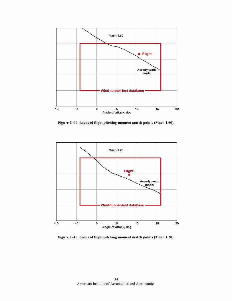
Presented in appendix C (comprised of Figs. C-01 through C-12) is a representative data ensemble generated in the application of the various pitching moment matching schemes previously described. In particular, the locus of angle-of-attack–elevator deflection combinations that result in the predicted pitching moment being equal to the flight value are shown along with the flight-measured angle of attack–elevator deflection combination. Data are provided for the complete spectrum of descent phase Mach numbers. The Mach numbers used in the analysis correspond with the break points found in the aerodynamic model used in the simulation. Superimposed on each plot are the angle-of-attack and elevator deflection limits of the aerodynamic model wind-tunnel database as well.
Several points are worth noting. First, as the HXRV decelerated, the flight angle-of-attack–elevator deflection combination migrated from a position below to a position above the locus of flight pitching moment matching points. For Scheme 1, this suggests a developing loss in elevator effectiveness since the elevator deflection required to produce a pitching moment match is less than flight hypersonically and greater than flight transonically (with the crossover point occurring near a speed of Mach 4). Second, the flight pitching moment cannot be matched at hypersonic Mach numbers using the Scheme 2 angle-of-attack adjustment approach. In general, the angle of attack required to match the flight pitching moment is greater than flight. Finally, Scheme 3 will always produce a match in

American Institute of Aeronautics and Astronautics
11
pitching moment, but will sacrifice how well other parameters match. The following paragraphs describe details of the results of these methods.
Appendix D presents the results of the longitudinal aerodynamic force and moment discrepancy resolution effort using the aforementioned pitching moment matching schemes. Figure D-01 shows the results of applying Scheme 1 to the problem. Indeed, it was found that a match with the flight-derived pitching moment can be achieved by driving the 6-DOF aerodynamic model using an adjustment in elevator deflection only. The elevator deflection required to match the flight pitching moment is compared with the flight elevator deflection in Fig. D-02. Here, it is noted that the elevator deflection required to achieve a pitching moment match varies from larger angles hypersonically to smaller angles transonically. Figure D-03 shows that matching the pitching moment does not guarantee a match in normal force across the descent phase. This is especially true at hypersonic speeds. Further, as depicted in Fig. D-04, the axial force discrepancy is also not resolved via an elevator-deflection-only adjustment.
Figure D-05 shows the results of attempting to match the predicted pitching moment with the flight-derived value via adjustment of the HXRV angle of attack, Scheme 2. Observe that a match can only be achieved for flight times beyond 85 s or equivalently for Mach numbers below approximately 5.3. Thus, a match cannot be achieved hypersonically. Figure D-06 shows the angle of attack required of the HXRV to provide a match below a speed of Mach 5.3. Between a speed of Mach 5.3 and a speed of Mach 4.0, the angle of attack required to provide a match is greater than the flight value with the opposite trend evident below a speed of Mach 4.0. Figures D-07 and D-08 clearly convey the point that in the Mach regime within which a pitching moment match occurs, simultaneous matching of the flight normal force and axial force, respectively, cannot be achieved using Scheme 2.
The above results are summarized in nondimensional form in Figs. D-09, D-10, and D-11. These figures are Mach plots of HXRV pitching moment coefficient, normal force coefficient, and axial force coefficient, respectively. Note that data from Scheme 3 are included. The conclusion to be drawn here is that none of the matching schemes provides a unified resolution of the longitudinal aerodynamic force and moment discrepancies.
Because of the broad Mach number range traversed during the HXRV cowl-closed flight, the possibility exists that there is no simple unified scheme that can account for the observed longitudinal aerodynamic force and moment discrepancies. Factors to be considered here include flight measurement technique, ground-based-test data fidelity, and synthesis of the aerodynamic model. Additional factors include unsteady atmospheric effects, wind-tunnel-model fidelity factors, wind-tunnel-model support method effects, and wind-tunnel-test facility flow calibrations. In typical ground tests, replication of flight-scale viscous flow phenomena such as skin friction and flow separation is not exact. These phenomena are chiefly functions of Mach number, Reynolds number, aerodynamic attitude (that is, angle of attack and angle of sideslip), vehicle surface roughness and temperature, and vehicle external airframe configuration (primarily shape and surface protuberances). Further, the aerodynamic pitching moment coefficient at zero angle of attack is traditionally difficult to accurately obtain from ground-based tests. To account for these unknown quantities, uncertainty models for the ground-based aerodynamic models are intentionally conservative in nature. A case in point can be seen during the wind-tunnel testing of the Space Shuttle as seen in Ref. 11. Reference 12 provides more information on what needs to be considered when building an aerodynamic model from wind tunnel data.
As indicated earlier, the wind-tunnel models were constructed and tested in the cowl-closed configuration. Here, the engine inlet and exit faces were modeled as solid flat surfaces since it was logically assumed that there would be no flow through the engine with the cowl door closed. The fullscale X-43A cowl door does, however, in fact permit some extraneous flow through the scramjet engine in the closed configuration. This circumstance has been confirmed by scramjet engine internal pressure measurements made during flight 2. The presence of flow through the fullscale scramjet engine in the cowl-closed configuration implies not only the existence of vehicle internal forces and moments, but modification of the lower surface aerodynamics as well (the main effect here being the modification of the X-43A nozzle region aerodynamic forces and moments caused by the extraneous flow coming out of the scramjet engine exit).
F. Flight-Extracted Lateral–Directional Aerodynamics The HXRV flight-extracted lateral–directional aerodynamics (that is, BAS side force, rolling moment, and
yawing moment) is presented in appendix E. This section also includes aerodynamic data obtained by driving the HXRV 6-DOF aerodynamic model at flight conditions. As was the case for the longitudinal aerodynamics, the purpose of driving the model was to evaluate how accurately HXRV cowl-closed aerodynamic forces and moments are replicated by the aerodynamic model. Aerodynamic model results were generated for both the BET and INS air data sets.

American Institute of Aeronautics and Astronautics
12
G. Body Axis System Side Force Figures E-01 through E-03 pertain to the flight-extracted BAS side force during the HXRV descent phase. Figure
E-01 presents the side force time history for this period of flight. The measured side forces are very small, which is indicative of flight at very low angle of sideslip (Fig. A-05). During the pre-MS flight segment, there is excellent agreement between the aerodynamic model and the flight-measured values. This is largely due, however, to the existence of very small angles of sideslip. The aerodynamic model side force increases as angle of sideslip increases while the HXRV decelerates and descends. Figure E-02 shows that the side force differential increases as well, but is typically small during the MS-1, MS-2, and MS-3 maneuver sequences. As the HXRV descends below an altitude of 50,000 ft msl and decelerates below a speed of Mach 1.5, the side force differential exhibits a precipitous increase near a speed of Mach 1 in the post-MS period. Figure E-03 illustrates the fact that the side force differential generally lies within the flight data 3-σ-uncertainty band through completion of the MS maneuver sequence, but well outside it during post-MS flight. In contrast, the side force differential lies well outside the aerodynamic model 3-σ-uncertainty band throughout the descent. This is a consequence of (1) the relatively high uncertainty in knowing the atmospheric properties (especially atmospheric winds) far downrange and (2) the increasing influence that atmospheric winds have on the air data state as the X-43A decelerates into the transonic and subsonic Mach regimes.
H. Body Axis System Rolling Moment Figures E-04 through E-06 pertain to the flight-extracted BAS rolling moment during the HXRV descent phase.
The flight-measured rolling moment time history is presented in Fig. E-04. The HXRV is trimmed in roll throughout flight as evidenced by the very low-amplitude, high-frequency rolling moment oscillation about the zero rolling moment. However, the aerodynamic model does not display this behavior at all with departures from trim registering values in the hundreds of ft-lbf. Note that the growing differences between the BET and INS air data (Figs. A-01 through A-05) as the HXRV descends cause a corresponding disparity between the associated aerodynamic model results. Figure E-05 presents the rolling moment differential observed during the descent phase. Figure E-06 superimposes the 6-DOF aerodynamic model and flight-derived 3-σ uncertainty bands over the rolling moment differentials contained in the previous plot. The flight data rolling moment uncertainties are quite small since roll channel dynamic motion is very benign when the vehicle flies at trim. Note that the rolling moment differential generally lies well outside both bands. The high uncertainty in atmospheric thermodynamic properties and wind conditions that accounts for the significant side force discrepancies discussed earlier also applies to the large rolling moment discrepancies.
I. Body Axis System Yawing Moment Figures E-07 through E-09 pertain to the flight-extracted BAS yawing moment during the HXRV descent phase. Figure E-07 depicts the time variation of the HXRV yawing moment for the Hyper-X flight 2 descent phase. As was the case for the side force and rolling moment, the flight-measured yawing moment is small and oscillates about the zero yawing moment point. Again, this behavior is symbolic of trimmed flight and, as was the case for rolling moment, the aerodynamic model using BET and INS air data look nothing like the flight data. As shown in Fig. E-08, the differential between the aerodynamic model and flight yawing moments is generally quite small during the pre-MS and MS-1 periods due to the associated small angles of sideslip. The differential grows, however, as the HXRV descends and the angle of sideslip increases. Differentials on the order of several hundred ft-lbf are observed during the MS-2 through MS-4 maneuvers, increasing to large values in the post-MS phase. As was the case for the rolling moment, except for the pre-MS flight segment, the yawing moment differential lies well beyond both the 3-σ aerodynamic model and flight-based uncertainty bands as seen in Fig. E-09. Once again, the high uncertainty in atmospheric thermodynamic properties and wind conditions that accounts for both the side force and rolling moment discrepancies also applies to the yawing moment discrepancies.
J. Lateral–Directional Aerodynamics Discrepancy Resolution As was the case for the longitudinal aerodynamic force and moment discrepancies, an effort was made to devise
and validate a simple, unified scheme for matching the aerodynamic model predictions with the flight lateral–directional aerodynamics. The primary adjustment factors considered in this instance were the HXRV angle of sideslip, rudder deflection, and aileron deflection. In contrast with the longitudinal case, a simple unified matching scheme was indeed found for resolving the lateral–directional aerodynamic force and moment discrepancies. Specifically, adjustment of the angle of sideslip provided an excellent match between the aerodynamic model and flight-measured yawing moments. Likewise, the angle-of-sideslip increment derived in resolving the yawing moment discrepancy also provided an excellent match for the side force and rolling moments. Appendix F presents

American Institute of Aeronautics and Astronautics
13
the results of this matching exercise. In particular, Figs. F-01, F-02, and F-03 present the matched yawing moment, rolling moment, and side force, respectively.
Figure F-04 shows the time variation of the angle-of-sideslip adjustment required to resolve the Hyper-X flight yawing moment discrepancy. Early in the descent, when the HXRV was flying at high altitude, observe that the angle-of-sideslip discrepancy is negligible since the aerodynamic model and flight-derived yawing moments are in extremely close agreement (Fig. E-07). This is not surprising in light of the fact that the angle of sideslip is also very small (Fig. A-05). The key point to note here, however, is the negligibly small difference between the BET- and INS-derived angles of sideslip (Fig. A-05). The winds at altitude during this stage of the descent were small in magnitude in comparison to the overall speed of the HXRV. As the HXRV descended and decelerated, the differences between the BET- and INS-derived angle of sideslip are seen to increase. This implies that atmospheric winds were being encountered at lower altitudes, where the vehicle was flying at a slower speed. A secondary contributing factor is the presence of INS drift. To complete this picture, recall that the previously-cited yawing moment discrepancy (Fig. E-07) and corresponding angle-of-sideslip adjustment continually increase with decreasing altitude.
Improving the flight force and moment determination requires accurate knowledge of the HXRV air data state vector (ADSV). The ADSV consists of the Mach number, dynamic pressure, angle of attack, and angle of sideslip relative to the air mass. The ADSV is a function of the HXRV inertial velocity components, atmospheric density, atmospheric temperature, and atmospheric winds (magnitude and direction). An INS alone does not provide vehicle state relative to the air mass when the air mass is moving relative to the inertial frame. A full air data system is required to obtain the ADSV. The only ADSV function computed during the flight 2 descent phase was the angle of attack as provided by a flush air data sensing (FADS) system. The FADS-derived angle of attack was blended with that from the INS to obtain an improved angle-of-attack estimate. This hybrid implementation was successfully applied in real-time during the flight 2 descent phase. Systems that compute the full ADSV could significantly improve the force and moment determination of the HXRV especially at the lower Mach numbers and altitudes where atmospheric winds have a greater effect on HXRV aerodynamics.
There are two primary ways to improve the accuracy of both the BET- and INS-derived angles of sideslip. The first approach is implemented postflight and involves the use of many rawindsonde balloons launched along the HXRV descent trajectory throughout the mission. The second approach involves the use of a FADS system, which inherently accounts for the presence of atmospheric winds. A further benefit here is that FADS utilization can accommodate both real-time and postflight implementations.
VIII. Conclusion The analysis of the flight-measured Hyper-X research vehicle aerodynamic force and moments for the descent
phase of flight 2 yielded the following results: 1) Nontrivial discrepancies exist between the predicted and the flight-measured longitudinal aerodynamic forces
and moments. With the exception of the normal force, these discrepancies generally lie well outside the aerodynamics model and flight-derived 3-σ uncertainty bands.
2) Elevator deflection and angle-of-attack adjustments, applied individually or jointly, do not provide a unified means of matching the aerodynamics model longitudinal force and moments prediction with flight measurements.
3) The longitudinal aerodynamics prediction versus flight discrepancies may largely be due to differences between the Hyper-X research vehicle wind-tunnel test simulation and fullscale flight. This was exacerbated by not knowing the true state of flight (angle of attack, dynamic pressure, et cetera) of the vehicle.
4) Nontrivial discrepancies exist between the predicted and flight-measured lateral–directional aerodynamic forces and moments. With the exception of side force, these discrepancies generally lie well outside the aerodynamics model and flight-derived 3-σ uncertainty bands.
5) Adjustment of the angle of sideslip provides a unified means of matching the aerodynamics model lateral–directional force and moment predictions with flight-measured values.
6) Knowledge of the true instantaneous angle of attack and angle of sideslip requires accurate and instantaneous knowledge of the atmospheric wind magnitude and direction along the flightpath. The only viable means for improving upon the accuracy of either best-estimated-trajectory- or inertial-navigation-system-derived angle of sideslip is through the use of a flush air data sensing system. This is particularly true for hypersonic flight vehicles, because they attain ranges that can be measured in hundreds or thousands of miles from the meteorological sampling site.

American Institute of Aeronautics and Astronautics
14
7) Flight test has always been the ultimate determinant of the true aerodynamic characteristics of an experimental flight vehicle. This is especially true in the case of the X-43A, the world’s first airframe-integrated scramjet-powered hypersonic aircraft.
References 1. Hunt, J. L., and Eiswirth, E. A., “NASA’s Dual-Fuel Airbreathing Hypersonic Vehicle Study,” AIAA-96-4591, 1996. 2. Marshall, L. A., Corpening, G. P., and Sherrill, R., A Chief Engineer’s View of the NASA X-43A Scramjet Flight Test,
NASA/TM-2005-212867, 2005. 3. Freeman, D. C., Jr., Reubush, D. E., McClinton, C. R., Rausch, V. L., and Crawford, J. L., The NASA Hyper-X Program,
NASA TM-1997-207243, 1997. 4. Sim, A. G., Flight-Determined Stability and Control Characteristics of the M2-F3 Lifting Body Vehicle, NASA TN
D-7511, 1973. 5. Iliff, K. W., and Shafer, M. F., Extraction of Stability and Control Derivatives From Orbiter Flight Data, NASA Technical
Memorandum 4500, 1993. 6. Sim, A. G., A Correlation Between Flight-Determined Derivatives and Wind-Tunnel Data for the X-24B Research
Aircraft, NASA TM-113084, 1997. 7. Young, J. C., and Underwood, J. M., “Development of Aerodynamic Uncertainties for the Space Shuttle Orbiter,” Journal
of Spacecraft and Rockets, Vol. 20, No. 6, 1983, pp. 513–517. 8. Cobleigh, B. R., Development of the X-33 Aerodynamic Uncertainty Model, NASA/TP-1998-206544, 1998. 9. Weil, J., and Powers, B. G., Correlation of Predicted and Flight-Derived Stability and Control Derivatives – with
Particular Application to Tailless Delta Wing Configurations, NASA TM-81361, 1981. 10. Gainer, T. G., and Hoffman, S., “Summary of Transformation Equations and Equations of Motion Used in Free-Flight
and Wind-Tunnel Data Reduction and Analysis,” NASA SP-3070, 1972. 11. Young, J. C., Perez, L. F., Romere, P. O., and Kanipe, D. B., “Space Shuttle Entry Aerodynamic Comparisons of Flight 1
with Preflight Predictions,” AIAA-1981-2476, 1981. 12. Maus, J. R., Griffith, B. J., Szema, K. Y., and Best, J. T., “Hypersonic Mach Number and Real Gas Effects on Space
Shuttle Orbiter Aerodynamics,” Journal of Spacecraft and Rockets, Vol. 21, No. 2, 1984, pp. 136–141.

American Institute of Aeronautics and Astronautics
15
Figures
Figure 1. The four flight phases of the X-43A vehicle.

American Institute of Aeronautics and Astronautics
16
Figure 2. Three-view of the Hyper-X research vehicle.
Figure 3. The Hyper-X research vehicle being prepared for flight.

American Institute of Aeronautics and Astronautics
17
Figure 4. The body axis system and body axis forces and moments of the Hyper-X research vehicle.
Figure 5. The design coordinate system of the Hyper-X research vehicle.

American Institute of Aeronautics and Astronautics
18
Figure 6. Pitching moment matching schemes.

American Institute of Aeronautics and Astronautics
19
Appendix A
Figure A-01. Mach number time history.
Figure A-02. Geometric altitude time history.

American Institute of Aeronautics and Astronautics
20
Figure A-03. Dynamic pressure time history.
Figure A-04. Angle-of-attack time history.

American Institute of Aeronautics and Astronautics
21
Figure A-05. Angle-of-sideslip time history.
Figure A-06. Elevator deflection time history.

American Institute of Aeronautics and Astronautics
22
Figure A-07. Rudder deflection time history.
Figure A-08. Aileron deflection time history.

American Institute of Aeronautics and Astronautics
23
Appendix B
Figure B-01. Flight-extracted axial force.
Figure B-02. Axial force differential.

American Institute of Aeronautics and Astronautics
24
Figure B-03. Axial force differential (percentage of flight value).
Figure B-04. Axial force differential relative to 3-σ uncertainties.

American Institute of Aeronautics and Astronautics
25
Figure B-05. Flight-extracted normal force.
Figure B-06. Normal force differential.

American Institute of Aeronautics and Astronautics
26
Figure B-07. Normal force differential (percentage of flight value).
Figure B-08. Normal force differential relative to 3-σ uncertainties.

American Institute of Aeronautics and Astronautics
27
Figure B-09. Flight-extracted pitching moment.
Figure B-10. Pitching moment differential.

American Institute of Aeronautics and Astronautics
28
Figure B-11. Pitching moment differential relative to 3-σ uncertainties.
Figure B-12. Flight longitudinal center of pressure.

American Institute of Aeronautics and Astronautics
29
Figure B-13. Aerodynamic-model-predicted longitudinal center of pressure.
Figure B-14. Center-of-pressure differential.

American Institute of Aeronautics and Astronautics
30
Appendix C
Figure C-01. Locus of flight pitching moment match points (Mach 6.60).
Figure C-02. Locus of flight pitching moment match points (Mach 5.93).

American Institute of Aeronautics and Astronautics
31
Figure C-03. Locus of flight pitching moment match points (Mach 4.60).
Figure C-04. Locus of flight pitching moment match points (Mach 3.50).

American Institute of Aeronautics and Astronautics
32
Figure C-05. Locus of flight pitching moment match points (Mach 2.80).
Figure C-06. Locus of flight pitching moment match points (Mach 2.50).

American Institute of Aeronautics and Astronautics
33
Figure C-07. Locus of flight pitching moment match points (Mach 2.10).
Figure C-08. Locus of flight pitching moment match points (Mach 1.80).
American Institute of Aeronautics and Astronautics
34
Figure C-09. Locus of flight pitching moment match points (Mach 1.60).
Figure C-10. Locus of flight pitching moment match points (Mach 1.20).

American Institute of Aeronautics and Astronautics
35
Figure C-11. Locus of flight pitching moment match points (Mach 1.05).
Figure C-12. Locus of flight pitching moment match points (Mach 0.95).

American Institute of Aeronautics and Astronautics
36
Appendix D
Figure D-01. Matching of flight pitching moment via elevator deflection adjustment (scheme 1).
Figure D-02. Elevator deflection required to match flight pitching moment (scheme 1).

American Institute of Aeronautics and Astronautics
37
Figure D-03. Normal force associated with matching of flight pitching moment using elevator deflection adjustments.
Figure D-04. Axial force associated with matching of flight pitching moment using elevator deflection adjustments.

American Institute of Aeronautics and Astronautics
38
Figure D-05. Matching of flight pitching moment via angle-of-attack adjustment (scheme 2).
Figure D-06. Angle of attack required to match flight pitching moment (scheme 2).

American Institute of Aeronautics and Astronautics
39
Figure D-07. Normal force associated with matching of flight pitching moment using angle-of-attack adjustments.
Figure D-08. Axial force associated with matching of flight pitching moment using angle-of-attack adjustments.

American Institute of Aeronautics and Astronautics
40
Figure D-09. Matching of flight pitching moment at selected Mach numbers.
Figure D-10. Normal force associated with matching of flight pitching moment.

American Institute of Aeronautics and Astronautics
41
Figure D-11. Axial force associated with matching of flight pitching moment.

American Institute of Aeronautics and Astronautics
42
Appendix E
Figure E-01. Flight-extracted side force.
Figure E-02. Side force differential.

American Institute of Aeronautics and Astronautics
43
Figure E-03. Side force differential relative to 3-σ uncertainties.
Figure E-04. Flight-extracted rolling moment.

American Institute of Aeronautics and Astronautics
44
Figure E-05. Rolling moment differential.
Figure E-06. Rolling moment differential relative to 3-σ uncertainties.

American Institute of Aeronautics and Astronautics
45
Figure E-07. Flight-extracted yawing moment.
Figure E-08. Yawing moment differential.

American Institute of Aeronautics and Astronautics
46
Figure E-09. Yawing moment differential relative to 3-σ uncertainties.

American Institute of Aeronautics and Astronautics
47
Appendix F
Figure F-01. Matching of flight yawing moment via adjustment of sideslip.
Figure F-02. Rolling moment associated with matching of flight yawing moment via adjustment of sideslip.

American Institute of Aeronautics and Astronautics
48
Figure F-03. Side force associated with matching of flight yawing moment via adjustment of sideslip.
Figure F-04. The sideslip required to match the flight yawing moment.