flexscan l660/l661/l680 user's manual - eizo
TRANSCRIPT

User’s Manual
Color LCD Monitor

2 CONTENTS
CONTENTSPRECAUTIONS __________________________ 4
INTRODUCTION _________________________ 9About this Manual .................................................... 9Package Contents .................................................... 9Controls & Connectors ........................................... 10
1 INSTALLATION _______________________ 111-1 Connecting up ................................................. 11
PC Settings ....................................................................... 11Connecting the Cables ..................................................... 11Attaching an Arm to the Monitor ....................................... 13
2 USING THE SCREENMANAGER _________ 152-1 How to use the ScreenManager ...................... 15
About ScreenManager ...................................................... 15ScreenManager Menus .................................................... 15How to use the ScreenManager ....................................... 17Adjustment Lock ............................................................... 18
2-2 Screen Adjustment .......................................... 19About Screen Adjustments ............................................... 19Adjustment Procedure ...................................................... 20
2-3 Color Adjustment ............................................. 26About Color Adjustments .................................................. 26Color Mode ....................................................................... 26Gain Adjustments ............................................................. 26
2-4 Power-save Setup ........................................... 28Setup Procedure ............................................................... 28
2-5 Other Settings ................................................. 30About Other Settings ........................................................ 30Screen Size ...................................................................... 30Border Intensity ................................................................ 31Input Priority ..................................................................... 31Off Timer ........................................................................... 31Beep ................................................................................. 32Menu Position ................................................................... 33Reset ................................................................................ 33
3
E
CONTENTS
3 MAKING USE OF USB _________________ 34Setup Procedure ............................................................. 34Trouble Shooting ............................................................. 36
4 TROUBLESHOOTING _________________ 37
5 CLEANING __________________________ 41
6 SPECIFICATIONS _____________________ 42
APPENDIX______________________________ iPin Assignment ........................................................ iiPreset Timing Chart ................................................. iiiDimensions ............................................................. vi
Copyright© 2000 by EIZO NANAO CORPORATION. All rights reserved. No part ofthis manual may be reproduced, stored in a retrieval system, or transmitted, in any form orby any means, electronic, mechanical, or otherwise, without the prior written permission ofEizo Nanao Corporation.
Eizo Nanao Corporation is under no obligation to hold any submitted material orinformation confidential unless prior arrangements are made pursuant to Eizo NanaoCorporation's receipt of said information.
Although every effort has been made to ensure that this manual provides up-to-dateinformation, please note that EIZO monitor specifications are subject to change withoutnotice.
Apple and Macintosh are trademarks of Apple Computer Inc.,registered in the U.S. andother countries.DPMS is a trademark and VESA is a registered trademark of Video Electronics StandardsAssociation.VGA is a registered trademark of International Business Machines Corporation in the USAand other countries.ENERGY STAR is a U.S. registered mark.Windows is a registered trademark of Microsoft Corporation.ScreenManager, PowerManager, and i·Sound are trademarks of Eizo Nanao Corporation.FlexScan and EIZO are registered trademarks of Eizo Nanao Corporation.
4 PRECAUTIONS
PRECAUTIONS
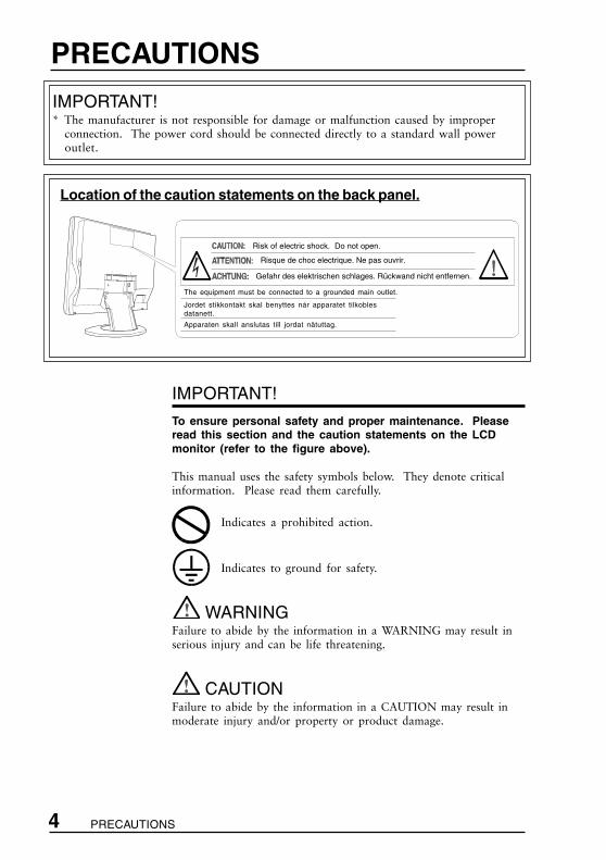
Location of the caution statements on the back panel.
IMPORTANT!* The manufacturer is not responsible for damage or malfunction caused by improper
connection. The power cord should be connected directly to a standard wall poweroutlet.
IMPORTANT!
To ensure personal safety and proper maintenance. Pleaseread this section and the caution statements on the LCDmonitor (refer to the figure above).
This manual uses the safety symbols below. They denote criticalinformation. Please read them carefully.
Indicates a prohibited action.
Indicates to ground for safety.
WARNINGFailure to abide by the information in a WARNING may result inserious injury and can be life threatening.
CAUTIONFailure to abide by the information in a CAUTION may result inmoderate injury and/or property or product damage.
Gefahr des elektrischen schlages. Rückwand nicht entfernen.
Risk of electric shock. Do not open.
Risque de choc electrique. Ne pas ouvrir.
Apparaten skall anslutas till jordat nätuttag.
Jordet stikkontakt skal benyttes nár apparatet tilkoblesdatanett.
The equipment must be connected to a grounded main outlet.

PRECAUTIONS 5
EWARNING
• If the LCD monitor begins to emit smoke, smells likesomething is burning, or makes strange noises,disconnect all power connections immediately and contactyour dealer for advice.
Attempting to use a malfunctioning LCD monitor can bedangerous.
• Do not dismantle the cabinet or modify the LCD monitor.
Dismantling the cabinet or modifying the monitor may result inelectric shock or burn.
• Keep small objects away from the LCD monitor.
Small objects may accidentally fall through the ventilation slotsinto the cabinet-leading to fire, shock or equipment damage.
• Keep liquids away from the LCD monitor.
Spillage into the cabinet may result in fire, electric shock, orequipment damage.
If an object or liquid falls/spills into the cabinet, unplug the LCDmonitor immediately. Have the unit checked by a qualifiedservice engineer before using it again.
• Do not touch a damaged LCD panel directly with barehands.
Use protective gloves whenever handling a damaged panel. Theliquid crystal which leaks from the panel is poisonous if it entersthe eyes or mouth. If any part of the skin or body comes in directcontact with the panel, please wash thoroughly. If some physicalsymptoms result, please consult your doctor.
• Take care in disposing of the LCD monitor.
The backlight of the LCD monitor contains mercury. Followlocal regulations or laws for safe disposal.
• Use the enclosed power cord. If using the power cordother than the enclosed one, use the following cord.In USA and Canada, use a UL LISTED/CSA LABELED orCERTIFIED power cord set meeting the following specifications:* Rating: min. 125 V, 10 A * Length: max. 2.0 m* Type: SVT* Plug type: NEMA 5-15P, Parallel blade, Grounding type,
125 V, 10 AIn Europe, use a proper European standard approved power cordmeeting the following specifications:* Rating: min. 250 V, 10 A * Length: max. 2.0 m* Type: H05VV-F 3G 1 mm2
Use a plug type approved by the country where you useFailure to do so may cause fire or electric shock.
6 PRECAUTIONS
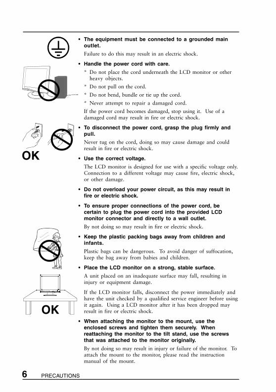
• The equipment must be connected to a grounded mainoutlet.
Failure to do this may result in an electric shock.
• Handle the power cord with care.
* Do not place the cord underneath the LCD monitor or otherheavy objects.
* Do not pull on the cord.
* Do not bend, bundle or tie up the cord.
* Never attempt to repair a damaged cord.
If the power cord becomes damaged, stop using it. Use of adamaged cord may result in fire or electric shock.
• To disconnect the power cord, grasp the plug firmly andpull.
Never tug on the cord, doing so may cause damage and couldresult in fire or electric shock.
• Use the correct voltage.
The LCD monitor is designed for use with a specific voltage only.Connection to a different voltage may cause fire, electric shock,or other damage.
• Do not overload your power circuit, as this may result infire or electric shock.
• To ensure proper connections of the power cord, becertain to plug the power cord into the provided LCDmonitor connector and directly to a wall outlet.
By not doing so may result in fire or electric shock.
• Keep the plastic packing bags away from children andinfants.
Plastic bags can be dangerous. To avoid danger of suffocation,keep the bag away from babies and children.
• Place the LCD monitor on a strong, stable surface.
A unit placed on an inadequate surface may fall, resulting ininjury or equipment damage.
If the LCD monitor falls, disconnect the power immediately andhave the unit checked by a qualified service engineer before usingit again. Using a LCD monitor after it has been dropped mayresult in fire or electric shock.
• When attaching the monitor to the mount, use theenclosed screws and tighten them securely. Whenreattaching the monitor to the tilt stand, use the screwsthat was attached to the monitor originally.
By not doing so may result in injury or failure of the monitor. Toattach the mount to the monitor, please read the instructionmanual of the mount.
OK
OK

PRECAUTIONS 7
E• Set the LCD monitor in an appropriate location.
* Do not install in a dusty or humid environment.
* Do not place near water.
* Do not place in a location where light shines directly on thescreen.
* Do not place near heat generating devices or a humidifier.
CAUTION
• At the end of the day, or if you plan to leave the LCDmonitor unused for an extended period, turn off the mainpower switch and disconnect the power cord from the wallsocket so that no power connections are made.
• To ensure safety, always unplug the LCD monitor beforecleaning it.
Cleaning the LCD monitor while it is plugged into a poweroutlet may result in electric shock.
• Never use thinner, benzene, or other strong solvents orabrasive cleaners, as these may cause damage to thecabinet or LCD panel.
• Periodically clean the area around the plug.
Build-up of dust, water, or oil on the plug may result in fire.
• Please keep the LCD monitor in a dust-free environment.
Dust accumulation within the LCD monitor may result in fire orequipment failure.
• Do not touch the plug or the power unit with wet hands.
Touching the plug with wet hands is dangerous and can causeelectrical shock.
• When handling the LCD monitor, please refer to thediagram.
Grip the bottom of the LCD monitor firmly with both handsensuring the panel faces outward before lifting.
• Handle with care to avoid scratching or damaging the panel.
If the LCD monitor becomes damaged, disconnect the powerimmediately and have the unit checked by a qualified serviceengineer before using it again. Using a LCD monitor after it hasbeen dropped may result in fire or electric shock.
• Disconnect the power cord when moving the LCD monitor.
Moving the LCD monitor with the cord attached or lifting it isdangerous. It may result in injury or equipment damage.
OK

8 PRECAUTIONS
• Use an easily accessible power outlet.
This will ensure that you can disconnect the power quickly in caseof a problem.
• Do not block the ventilation slots on the cabinet.
* Do not place books or any other papers on the ventilation slots.
* Do not install the monitor in a closed space.
* Do not use the monitor laying down or upside down.
* Do not remove the tilt-swivel stand.
Using the monitor in this way blocks the ventilation slotsand prevents proper airflow, leading to fire or other damage.
Others• The screen may have some defective pixels. These pixels
may appear as slightly light or dark areas on the screen.This is due to the characteristics of the panel itself, and notthe LCD product.
• The backlight of the LCD monitor has a fixed life span.
When the screen becomes dark or begins to flicker, please contactyour dealer.
• Take care when handling the LCD panel.
* Do not press on the panel or edge of the frame stronglyas this will result in damage to the screen. There will be printsleft on the screen if the pressed image is dark or black. Decreaseof the prints on the screen requires to keep white desktop pattern’son for L661, and black desktop pattern’s on for L680.
* Do not scratch or press on the panel with any sharp objects, suchas pencil or pen as this may result in damage to the panel.
* Cleaning the panel with a dirty or rough cloth may damage thepanel.
• Generally, for maximum viewing comfort position the LCDmonitor slightly below eye level. Staring at the LCD monitor forprolonged periods can cause eye strain. Be sure to take adequaterests. (A 10-minute rest period each hour is suggested.)

E
9 INTRODUCTION
About This ManualThis manual explains the precautions, features, specifications, andoperation of your EIZO LCD monitor. For convenience, a“ScreenManager Quick Reference” guide has been included which showshow to implement basic adjustments with the ScreenManager utility.
Package Contents
• If any of the above-listed items are missing or damaged, please contactyour local dealer for assistance.
• We recommend that you retain the original packing materials in case offuture need.
INTRODUCTION
Power Cord Signal Cable(MD-C87/100)
ScreenManagerQuick Reference
LCD MonitorViewing Angle L660 L661 L680Horizontal: 160° 140° 170°Vertical: 160° 140° 170°
User’s Manual
EIZO LCD Utility Disk(for Windows®/Dos/Macintosh)
Connector Cover
Rear Cover(attached to themonitor)
4 of 4 mm x 12 mmmounting screws
WarrantyRegistration Card

10 INTRODUCTION
Rear
Controls & Connectors
Front
Enter Button
Control ButtonsUp, down, right and left buttons areused to enter adjustments and settingswhen using the ScreenManager menu.
Auto Adjustment ButtonAutomatically centers the displayed imageand adjust Clock and phase.
Input Signal Selection Button Selects one of two D-Sub connectors as the active input.
Power ButtonSwitches the monitor’s power ON andOFF only when the main power is ON.
Power IndicatorIndicates the power-on status in thefollowing ways:Green (Solid): Power is ON
(Flashing): Power is switchingoff in 15 minutes(See page 32.)
Yellow (Solid): Power Saving Mode(Flashing): Power is OFF
(Main power’s ON.)
PowerTerminalCovers forthe Optionalperipheral
4 Holes for Mounting an Arm-Stand
Security LockAllows for connection of a security cable.This lock supports the Kensington’sMicroSaver security system. For furtherinformation, please consult below:Kensington Technology Group2855 Campus Drive, San Mateo, CA94403 USA800-650-4242, x3348Intl: 650-572-2700, x3348Fax: 650-572-9675http://www.kensington.com
PowerConnector
Maintenance PortService use only.
USB Ports (Upstream Port x 1)On USB ports, see page 34 for further details.
USB Ports(Downstream Port x 4)
2 x D-Sub mini 15 pin Input Connectors
PowerSwitch

E
111 INSTALLATION
1-1 Connecting up
PC Settings
Before connecting your PC to the LCD monitor, change the display screensettings (resolution and frequency) in accordance with those below.
fH: 27 kHz-82 kHz fV: 50 Hz-85 Hz
• The maximum resolution of this LCD monitor is 1280 x 1024 at amaximum fV of 75 Hz.
Using the LCD monitor with Windows® 95/98
A Monitor information file is saved in the EIZO LCD Utility Disk includedin the package. It includes all the LCD required information for bestoperation with Windows 95/98. Please install the enclosed utility and select“EIZO L660/L661/L680” from the monitor list in Windows 95/98.
For installation procedure, please read the readme.txt in the utility disk.
Connecting the Cables
(1)Be sure that the power switches of both the PC and the LCD monitor areOFF.
(2)Remove the rear cover from the monitor. When removing the rear cover,push down the buttons while pulling.
(3)Plug the signal cable into the D-Sub connector at the rear of the monitor.Please ensure that the arrow mark on the casing of the connector isvisible when connecting.
When connecting the signal cable, check that the shape of the cableconnector matches the shape on the LCD monitor.
1 INSTALLATION
buttons

12 1 INSTALLATION
(4)Plug the other end of the cable into the video connector on the rear ofthe PC.
Standard PC graphics board
Macintosh
(5)Plug the power cord into the power connector on the rear of the LCDmonitor.
(6)Replacing the connector cover and the rear cover.
a) Insert the rear cover into the inlets at the bottom of the stand.
b) To close easily, the LCD monitor should be tilted forward. Attachthe connector cover to the rear panel of the LCD.
(7)Plug the other end of the power cord into a power outlet.
(8)Turn on the monitor’s main power and then switch on the PC power.Whenever you finish your operation, turn off the PC and the monitor.
Signal Cable (enclosed)
Standard PCgraphics board
D-Sub mini15pin
D-Sub mini15pin
Macintosh
Macintosh G3(Blue & White)
Macintosh Adapter DSCR-153 (optional)
Signal Cable (enclosed)
D-Sub mini15pin
D-Sub mini15pin
Signal Cable (enclosed)
D-Sub mini15pin
D-Sub 15pin
D-Sub mini15pin
21

E
131 INSTALLATION
Attaching an Arm Stand to the Monitor
WARNING
• When attaching the monitor to the mount, use the enclosed screwsand tighten them securely. When reattaching the monitor to the tiltstand, use the screws that was attached to the monitor.
By not doing so may result in injury or failure of the monitor. To attach themount to the monitor, please read the instruction manual of the mount.
• Use a VESA approved arm-stand. The LCDpanel requires 100 mm x 100 mm hole spacingon the arm mounting pad. The arm-stand shouldbe able to support an object weighing 13.5 kg.
• In case of using this LCD monitor with an arm-stand in an office workspace, the arm-standshall be chosen and used carefully:
- Use only an approved arm-stand (e.g. GS).
- The arm-stand shall have sufficient stability(mechanical firmness) to support the weightof the monitor.
- The arm-stand shall remain in that positionwhere it is manually moved.
- The arm-stand shall have the ability to tilt themonitor forward and backward.
- The height of the upper row shall be lessthan or equal to 500 mm in relation tothe desk surface when the arm-stand isin its lowest position.
(1)Lay the LCD monitor as shown below, not scratching the panel.Remove the tilt loosening the screws. When reattaching the tilt, use theenclosed screws and fix the tilt to the monitor securely.
Soft Clothor Cushion
500 mm
(Example)
100 mm x100 mm
• Do your part to conserve energy, turn off the monitor when youare finished using it.
14 1 INSTALLATION
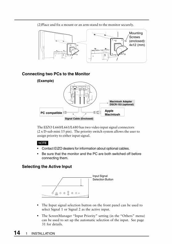
(2)Place and fix a mount or an arm-stand to the monitor securely.
Connecting two PCs to the Monitor
(Example)
The EIZO L660/L661/L680 has two video input signal connectors(2 x D-sub mini 15 pin). The priority switch system allows the user toassign priority to either input signal.
• Contact EIZO dealers for information about optional cables.
• Be sure that the monitor and the PC are both switched off beforeconnecting them.
Selecting the Active Input
• The Input signal selection button on the front panel can be used toselect Signal 1 or Signal 2 as the active input.
• The ScreenManager “Input Priority” setting (in the “Others” menu)can be used to set up the automatic selection of the input. See page31 for details.
Signal Cable (Enclosed)
Macintosh AdapterDSCR-153 (optional)
AppleMacintoshPC compatible
Input SignalSelection Button
MountingScrews(enclosed):4x12 (mm)
E
152 USING THE SCREENMANAGER
2-1 How to use the ScreenManager
About ScreenManager
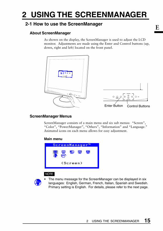
As shown on the display, the ScreenManager is used to adjust the LCDmonitor. Adjustments are made using the Enter and Control buttons (up,down, right and left) located on the front panel.
ScreenManager Menus
ScreenManager consists of a main menu and six sub menus: “Screen”,“Color”, “PowerManager”, “Others”, “Information” and “Language.”Animated icons on each menu allows for easy adjustment.
Main menu
• The menu message for the ScreenManager can be displayed in sixlanguages: English, German, French, Italian, Spanish and Swedish.Primary setting is English. For details, please refer to the next page.
2 USING THE SCREENMANAGER
Enter Button Control Buttons

16 2 USING THE SCREENMANAGER
Sub menus
<Screen>
<Color>
<PowerManager>
<Others>
page 19
page 26
page 28
page 30
ReferenceFunctions
<Information>This menu shows the current ScreenManagersettings. The menu contains three pages.Pressing the ENTER key displays thefollowing information:
• Page 1: “Screen” menu settings
• Page 2: “Color” and “PowerManager”settings
• Page 3: “Others” menu settings
· The current ScreenManager setting isdisplayed even if the input selection hasbeen manually overridden by the use of theinput signal selection button.
<Language>First select the preferred language to use.The ScreenManager’s messages will appearin the selected language. This will becomethe default language when you use theScreenManager.
E
172 USING THE SCREENMANAGER
How to use the ScreenManager
Entering the ScreenManager
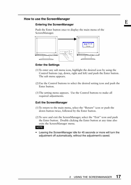
Push the Enter button once to display the main menu of theScreenManager.
Enter the Settings
(1)To enter any sub menu icon, highlight the desired icon by using theControl buttons (up, down, right and left) and push the Enter button.The sub menu appears.
(2)Use the Control buttons to select the desired setting icon and push theEnter button.
(3)The setting menu appears. Use the Control buttons to make allrequired adjustments.
Exit the ScreenManager
(1)To return to the main menu, select the “Return” icon or push thedown button twice, followed by the Enter button.
(2)To save and exit the ScreenManager, select the “Exit” icon and pushthe Enter button. Double clicking the Enter button at any time alsoexits the ScreenManager menu.
• Leaving the ScreenManager idle for 45 seconds or more will turn theadjustment off automatically, without the adjustment's saved.

18 2 USING THE SCREENMANAGER
Shortcut keys
Brightness and contrast can be adjusted directly without any need toenter the ScreenManager. Press the Control buttons to adjust the settingsand then the Enter button to save all changes.See the diagram below for adjustment directions.The brightness and contrast functions are also available in theScreenManager “Screen” menu.
Adjustment Lock
The ScreenManager operation can be disabled by holding down the Autoadjustment button while switching on the LCD monitor’s power. Thiswill disable (“lock”) the Enter button and Auto adjustment button,protecting from accidental changes. To unlock the buttons, switch thepower off. Switch the power on while pressing the Auto adjustmentbutton.
Note the brightness and contrast can be adjusted using the shortcut keyseven while the Enter button is locked. After making such an adjustment,the Enter button can be used to clear the brightness/contrast adjustmentmenu from the screen. Furthermore, the Input signal selection buttoncan still be used while the adjustment lock is on.
Power Button
Auto Adjustment button
Brightnessup
Brightnessdown
Contrastdown
Contrastup
E
192 USING THE SCREENMANAGER
2-2 Screen Adjustment
About Screen Adjustments
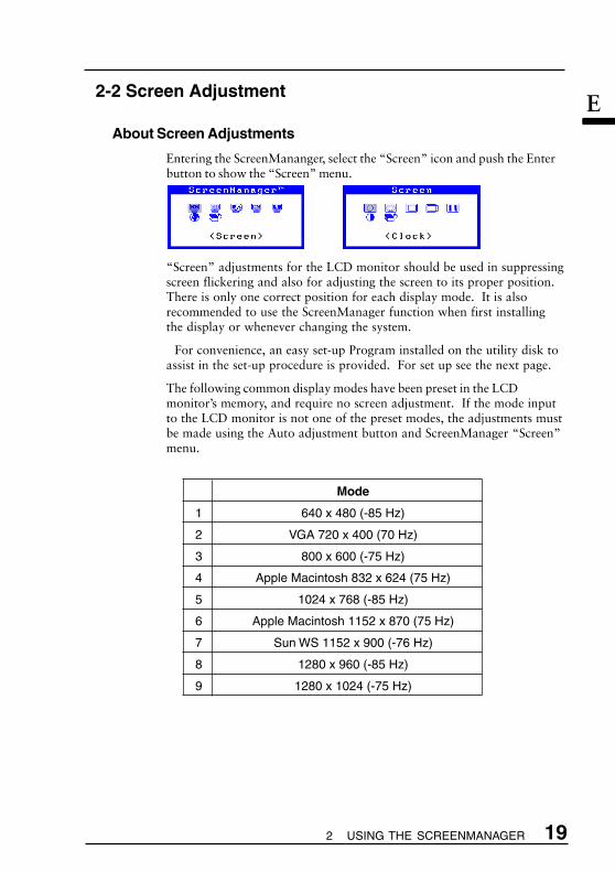
Entering the ScreenMananger, select the “Screen” icon and push the Enterbutton to show the “Screen” menu.
“Screen” adjustments for the LCD monitor should be used in suppressingscreen flickering and also for adjusting the screen to its proper position.There is only one correct position for each display mode. It is alsorecommended to use the ScreenManager function when first installingthe display or whenever changing the system.
For convenience, an easy set-up Program installed on the utility disk toassist in the set-up procedure is provided. For set up see the next page.
The following common display modes have been preset in the LCDmonitor’s memory, and require no screen adjustment. If the mode inputto the LCD monitor is not one of the preset modes, the adjustments mustbe made using the Auto adjustment button and ScreenManager “Screen”menu.
Mode
1 640 x 480 (-85 Hz)
2 VGA 720 x 400 (70 Hz)
3 800 x 600 (-75 Hz)
4 Apple Macintosh 832 x 624 (75 Hz)
5 1024 x 768 (-85 Hz)
6 Apple Macintosh 1152 x 870 (75 Hz)
7 Sun WS 1152 x 900 (-76 Hz)
8 1280 x 960 (-85 Hz)
9 1280 x 1024 (-75 Hz)

20 2 USING THE SCREENMANAGER
Adjustment Procedure
Overview
• Allow the LCD monitor to warm up for at least 20 minutes beforemaking adjustments.
• To make adjustment easily, install and run the “Screen AdjustmentProgram” in the attached utility disk. Before adjustment, read the“readme.txt” file.
• Do not continuously press the Control buttons (up, down, right and leftbuttons) on the front panel, as the adjustment value will change quicklyand make it difficult to locate the most suitable adjustment point.
(1) Install and run the "Screen Adjustment Program" in the utility disk.
(2) Push the Auto adjustment button.
(3) Enter the ScreenManager and select the "Screen" menu.
Horizontal bars appear. OK
(9) Exit the ScreenManager.
(4) "Clock" adjustment
(5) "Phase" adjustment
(6) "Position" adjustment
(8) "Contrast/Brightness" adjustment
(7) Confirm the "Resolution".

E
212 USING THE SCREENMANAGER
Procedure
Please adjust the screen using the following procedure.
(1)Having read the “readme.txt” file, install and run the “ScreenAdjustment Program” in the utility disk.
Step by step adjustment is provided by the wizard guide. Follow thewizard or the procedures (2) to (8) below.
• If the user's operation system has no utility disk (e.g. OS/2), werecommend setting the desktop pattern to that as shown in thediagram below.
(2) Auto AdjustmentPush the Auto adjustment button on the front panel. The followingmessage will appear and remain on the screen for 5 seconds. Whilethe message is on the screen, push the button again to automaticallyadjust the screen position. If you do not wish to do adjust the screen,do not push the button again. The message will disappear.
• The Auto adjustment function is intended for use on Macintosh andPCs running Windows. It may not function properly if any of thefollowing applies:
• PC running MS-DOS (not Windows).
• The background color for the “wallpaper” or “desktop” pattern isset to black or dark.
• Some signals from some graphics boards may not functionproperly. Follow the adjustment procedure next page.
• During the Auto adjustment, some icons (e.g. clock icon) appearon the screen continuously.
Every-other-dot pattern
(Example)

22 2 USING THE SCREENMANAGER
Function
Decreases the vertical bars of distortion.a)Select the “Clock” icon and push the Enter
button to enter the “Clock” menu”b) If vertical bars appear, these can be eliminated
by adjusting the right and left buttons.i) If the screen is free from any bars of distor-
tion, proceed to “Position” adjustment.ii) If horizontal flickering or horizontal bars
appear, proceed to “Phase” adjustment.
· The LCD monitor is designed for analog inputsignals from a standard graphics board. Theanalog input signal is converted to a digital signalby the LCD circuitry. To convert the signalcorrectly, the LCD monitor needs to produce thesame number of clock pulses as the dot clock ofthe graphics system. When the clock pulse is notcorrectly set, some vertical bars of distortion aredisplayed on the screen.
· When adjusting the “Clock”, the horizontal screensize will also change.
(3) Enter the ScreenManager “Screen” menu.
(4) “Clock” Adjustment
E
232 USING THE SCREENMANAGER
Function
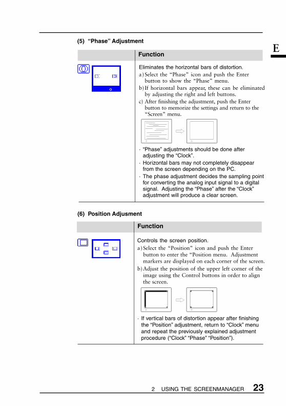
Eliminates the horizontal bars of distortion.a)Select the “Phase” icon and push the Enter
button to show the “Phase” menu.b) If horizontal bars appear, these can be eliminated
by adjusting the right and left buttons.c) After finishing the adjustment, push the Enter
button to memorize the settings and return to the“Screen” menu.
· “Phase” adjustments should be done afteradjusting the “Clock”.
· Horizontal bars may not completely disappearfrom the screen depending on the PC.
· The phase adjustment decides the sampling pointfor converting the analog input signal to a digitalsignal. Adjusting the “Phase” after the “Clock”adjustment will produce a clear screen.
(5) “Phase” Adjustment
Function
Controls the screen position.a)Select the “Position” icon and push the Enter
button to enter the “Position menu. Adjustmentmarkers are displayed on each corner of the screen.
b)Adjust the position of the upper left corner of theimage using the Control buttons in order to alignthe screen.
· If vertical bars of distortion appear after finishingthe “Position” adjustment, return to “Clock” menuand repeat the previously explained adjustmentprocedure (“Clock” “Phase” “Position”).
(6) Position Adjusment
24 2 USING THE SCREENMANAGER
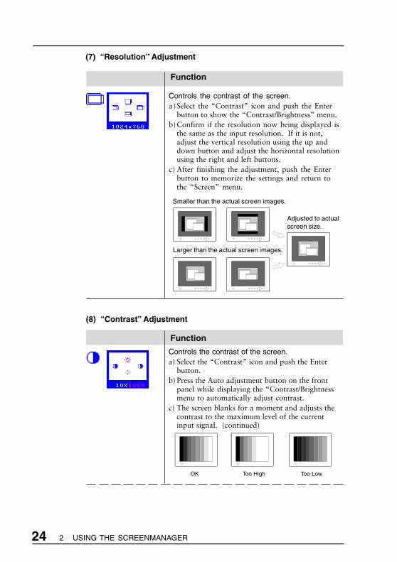
(7) “Resolution” Adjustment
Function
Controls the contrast of the screen.a)Select the “Contrast” icon and push the Enter
button to show the “Contrast/Brightness” menu.b)Confirm if the resolution now being displayed is
the same as the input resolution. If it is not,adjust the vertical resolution using the up anddown button and adjust the horizontal resolutionusing the right and left buttons.
c) After finishing the adjustment, push the Enterbutton to memorize the settings and return tothe “Screen” menu.
Adjusted to actualscreen size.
Smaller than the actual screen images.
Larger than the actual screen images.
Function
Controls the contrast of the screen.a) Select the “Contrast” icon and push the Enter
button.b) Press the Auto adjustment button on the front
panel while displaying the “Contrast/Brightnessmenu to automatically adjust contrast.
c) The screen blanks for a moment and adjusts thecontrast to the maximum level of the currentinput signal. (continued)
Too High Too LowOK
(8) “Contrast” Adjustment

E
252 USING THE SCREENMANAGER
Displays blurred texts distinct.
·This adjustment is disable when the resolutionis 1280 x 1024 or 1280 x 960.
Smoothing
Function
(9) Exit the ScreenManagera) To return to the main menu, select the “Return” icon or push the
down button twice, followed by the Enter button.
b) To exit the ScreenManager, select the “Exit” icon and push theEnter button. Double clicking the Enter button at any time alsoexits the ScreenManager menu.
• In the “Enlarged” mode and the “Full” mode (refer to the page 30), thefollowing adjustment is available.
Function
* In the case of the percentage color flickeringbetween yellow and white, please note that this isnot an error but actually the most optimumadjustment point.
* The brightness of the entire screen is controlledby changing the “Brightness” controls. Nocontrast adjustment is required except when thegraphics board or the resolution is changed fromthe previous one.
d) Adjust the “Brightness” as desired using the upand down button.
e) After finishing the adjustment, push the Enterbutton to memorize the settings and return to the“Screen” menu.

26 2 USING THE SCREENMANAGER
2-3 Color Adjustment
About Color Adjustments
Entering the ScreenManager, select the “Color” icon and push the enterbutton to show the “Color” menu.
The ScreenManager “Color” menu provides 3 color setting modes; 1, 2,and 3. You can also adjust the color settings for each mode and storethem for future use.
• Allow the monitor to warm-up for at least 20 minutes before makingan adjustment.
Color Mode
Adjusts: Color Mode
Mode 1(default): The normal white color. It isthe maximum contrast level.Please use this mode normally.
Mode 2: The white color tone isslightly bluish.
Mode 3: The white color tone isslightly reddish.
· The contrast level is reduced in Mode 2 and 3.(a) Select the “Color Mode” icon from the “Color”
menu and push the Enter button.(b) Select option 1, 2 or 3 and push the Enter
button. A long beep will be heard indicating theadjustment settings have been saved.
Function
Color Mode(Standard)
E
272 USING THE SCREENMANAGER
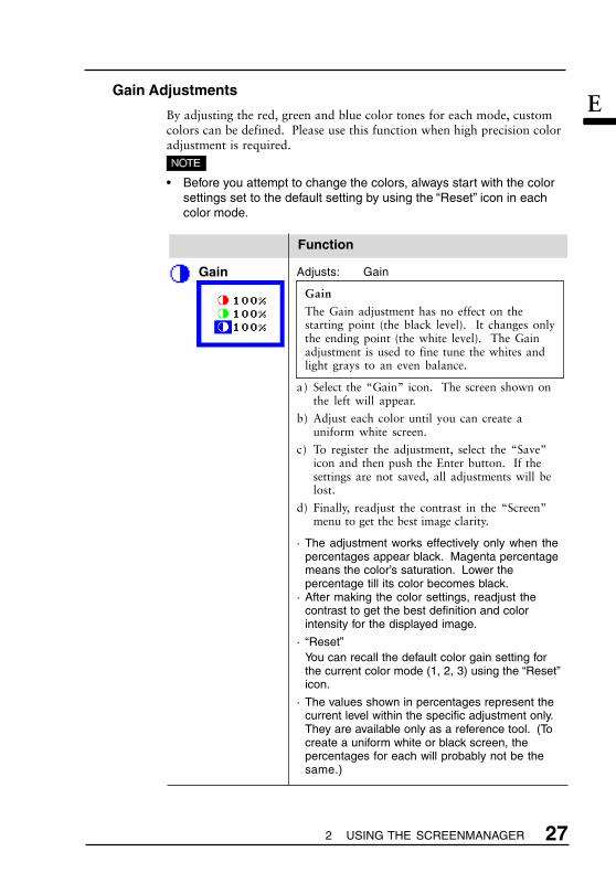
Gain Adjustments
By adjusting the red, green and blue color tones for each mode, customcolors can be defined. Please use this function when high precision coloradjustment is required.
• Before you attempt to change the colors, always start with the colorsettings set to the default setting by using the “Reset” icon in eachcolor mode.
Function
Adjusts: Gain
Gain
The Gain adjustment has no effect on thestarting point (the black level). It changes onlythe ending point (the white level). The Gainadjustment is used to fine tune the whites andlight grays to an even balance.
a) Select the “Gain” icon. The screen shown onthe left will appear.
b) Adjust each color until you can create auniform white screen.
c) To register the adjustment, select the “Save”icon and then push the Enter button. If thesettings are not saved, all adjustments will belost.
d) Finally, readjust the contrast in the “Screen”menu to get the best image clarity.
· The adjustment works effectively only when thepercentages appear black. Magenta percentagemeans the color’s saturation. Lower thepercentage till its color becomes black.
· After making the color settings, readjust thecontrast to get the best definition and colorintensity for the displayed image.
· “Reset”You can recall the default color gain setting forthe current color mode (1, 2, 3) using the “Reset”icon.
· The values shown in percentages represent thecurrent level within the specific adjustment only.They are available only as a reference tool. (Tocreate a uniform white or black screen, thepercentages for each will probably not be thesame.)
Gain

28 USING THE SCREENMANAGER
2-4 Power-save Setup
Power saving adjustment
The EIZO PowerManager functions comply withthe VESA DPMS standard and adopt a powersaving method, EIZO MPMS.
As an Energy Star® Partner, Eizo NanaoCorporation has determined that thisproduct meets the Energy Starguidelines for energy efficiency.
· Do your part to conserve energy, turn off themonitor when you are finished using it. Discon-necting the monitor from the power supply isrecommended to save energy completely.
· When the monitor is in a power saving mode, theoptional EIZO i·Sound speaker unit will turn off.
· Even if the monitor is in a power saving mode,USB compliant devices function when they areconnected to the monitor’s USB (both theupstream and the downstream ports). Therefore,power consumption of the monitor will changeaccording to the connected devices even if themonitor is in a power saving mode.
PowerManager
Function
Set-up Procedure
“VESA DPMS” system works with the VESA DPMS signal.“EIZO MPMS” system works with a screen saver software andEnergySaver for Macintosh which blanks the screen (totally black screen).
1) Set the monitor to match the PC’s power saving software, as follows.
• For the PC setup, please refer to the user’s manuals of the PC andthe graphics board.
Monitor setting for matching the PC:
PC PC Power saving Monitor setting
PC/AT and compatibles VESA DPMS (Signal) VESA DPMS(VESA DPMS activated)
PC/AT and compatibles Windows EIZO MPMS(VESA DPMS (Control Panel/Display/
inactivated) ScreenSaver: “Blank Screen”)
Macintosh Energy Saver EIZO MPMS
ScreenSaver software EIZO MPMSAfter Dark/“Blank” settings

E
292 USING THE SCREENMANAGER
2) Select “VESA DPMS” or “EIZO MPMS”.
• When “VESA DPMS” is selected, the monitor shifts into the powersaving mode in 5 seconds after recognizing either STAND-BY,SUSPEND, OR OFF signal. When “EIZO MPMS” is selected, themonitor shifts into the power saving mode in 5 seconds after PC'sScreenSaver blanks the screen.
VESA DPMS Power Saving Method
VESA DPMS utilizes four signals: ON, STANDBY, SUSPEND, and OFF.The monitor detects these signals from the graphics board and executespower saving accordingly, as illustrated below.
EIZO MPMS power saving method
If the keyboard or the mouse are not in use during operation, themonitor will enter PowerManager Mode
What is VESA DPMS?
The acronym VESA stands for “Video Electronics StandardsAssociation,” and DPMS stands for “Display Power ManagementSignaling.” DPMS is a communication standard that PCs andgraphics boards use to implement power savings at the monitor side.
What is EIZO MPMS?
EIZO MPMS, "EIZO Monitor PowerManager Signaling", also enablesto execute power saving at the monitor side. EIZO MPMS recognizesthe video signals from the PC when the PC is in a power saving mode,and reduces energy consumption of the monitor.
What is Energy Star?
“Energy Star” is a set of power-saving guidelines issued by the U.S.Environmental Protection Agency (EPA). The guidelines apply to PCsystems and peripherals.
Signal Screen LED Power Consumption
ON Operation Green 59 W(L660), 47 W(L661)67 W(L680)
STAND-BY/ Blank (power Yellow less than 3 WSUSPEND/OFF saving mode)
Signal Screen LED Power Consumption
ON Operation Green 59 W(L660), 47 W(L661)67 W(L680)
After Blank (power Yellow less than 3 WDuration saving mode)

30 2 USING THE SCREENMANAGER
2-5 Other Settings
About Other Settings
All of the icons shown in the ScreenManager “Others” menu aredescribed below.
Function
Screen Size Selects Screen Size
There are three screen size as follows.
Full Displays the picture on the screen in full,Screen irrespective of the picture's resolution.
Since the vertical resolution and thehorizontal resolution are enlarged indifferent rates, some images may appeardistorted.
Enlarged Displays the picture on the screen in full,Screen considering the width of the screen.
Since the pixel elements are fixed, somelines of the characters or pictures may bedisplayed with a different width.
Normal Displays the picture at the actualScreen resolution
· The resolution of 1280 x 960 and 1280 x 1024 donot change the screen sizes in the full screen orthe enlarged screen mode.
· At the “Enlarged” mode, “Smoothing” adjustment isavailable for having the blurred letters distinct.Please refer to the page 25.
Normal Enlarged Full
640 x 480 1280 x 960 1280 x 1024
1024 x 768 1280 x 960 1280 x 1024

E
312 USING THE SCREENMANAGER
Function
Changes the brightness of the black areasurrounding the displayed image.
· This adjustment is disable in full screen mode.
What is the “Border Intensity” function?
With lower resolutions of (640 x 480, 800 x 600,1024 x 768, etc.) the image is displayed at thecenter of the screen and the outer area (border) isusually black. The “Border Intensity” function canset the brightness of this border area to anybrightness level that maybe desired.
Selects which PC will have priority to control themonitor when utilizing two PCs.
Priority Performancesetting
If signals from both inputs are present, themonitor gives preference to Signal 1 for thecases shown below:• When the power of the monitor is turned
ON (see note 1).• When the signal input to Signal 1 is
changed even if active input was Signal 2.
If signals from both inputs are present, themonitor gives preference to Signal 2 for thecases shown below:• When the power of the monitor is turned
ON (see note 1).• When the signal input to Signal 2 is
changed even if active input was Signal 1.
The monitor will not detect signalsautomatically in this mode. Select the activeinput by pressing the input signal selectionbutton on the monitor’s front panel.
Input Priority
Automatically Turns off the Monitor
What is Off Timer?
The Off Timer function allows the user to set thetime in which the monitor will be in operation,called the “On Period” and automatically shifts theoperation into the “Power Off” mode when the set“On Period” expires. The Off Timer function wascreated to reduce afterimage characteristics thatare particular to LCD monitors when the monitorscreen is left on for a long period without use.
Off Timer
Signal 1
Signal 2
Manual
BorderIntensity

32 2 USING THE SCREENMANAGER
1)Select the “Off Timer” icon and press the Enterbutton to display “Off Timer” select menu.
2) Select “Enable” and press the enter button.3) Press the right/left key to adjust how long (1 to 23
hours) the monitor should be in the “On Period”.Then, press the enter button to return to the“others” menu.
4) Select the “Exit” icon and push the Enter buttonto exit the ScreenManager.
Advance notice (Beep and LED flashing green) willbe given 15 minutes before the monitor willautomatically turn off and enter the “Power Off”modes .
· “Off Timer” function works while Power Manager isactive, but there would be no advanced modebefore the monitor's power’s switching off.
To Delay Entering Power Off
To delay entering the “Power Off” mode, press thepower button on the front panel located to the left ofthe LED light during the advance notice period. Themonitor will continue to operate for an additional 90minutes. There will be another advance notice for15 minutes as described. Delayed entrance into the“Power Off” period can be extended as many timesas desired.
Function
Beep Turns the beeper on or off.
· ScreenManager item selected.· ScreenManager parameter adjusted
to minimum or maximum limit.· Input signal selection button pressed.
· Auto Adjustment button pressed.· ScreenManager data-save executed.
· Monitor not connected correctly.· PC turned off.· Monitor received unsupported signal
frequency.
· Monitor is in the advance notice modeof the Off Timer. The power will beoff within fifteen minutes.
Short beep
Long beep
Four shortbeeps
Two shortbeepseveryfifteen
seconds

E
332 USING THE SCREENMANAGER
Function
Menu Position Adjusts Menu's Position
Reset Returns to Factory Default
Default setting are as follows:
Screen: • Contrast 80 %• Brightness 100 %• Smoothing 3
Color • Mode 1/Normal white
PowerManager • VESA DPMS
Others • Screen Size Normal• Input Priority Signal 1• Off Timer: Disable• Beep On
Language • English
34 3 MAKING USE OF USB
This monitor provides a hub which supports the USB standard. Whenconnecting to a USB compliant PC or another hub, the monitor functions asa hub to which the USB compliant peripherals can be easily connected.
Required system environment
• PC equipped with USB ports or another USB hub connected to the USB compliant PC
• Windows 98/2000 // Mac OS 8.5.1 or later
• USB cable (Sold separately)
• The USB hub function may not work properly depending on the PC, OSor peripherals. Please consult the manufacturer of each device aboutthe USB support.
• When the monitor is not on, the peripherals connected to the down-stream ports will not operate.
• Even if the monitor is in a power saving mode, the devices connected tothe monitor’s USB ports (both the upstream and the downstream) willfunction.
Connecting to the USB HUB
• Do not connect the downstream port of the monitor to any peripheralsuntil finishing the USB function.
• The followings are procedures for the Windows 98 Second Edition/2000and Mac OS.
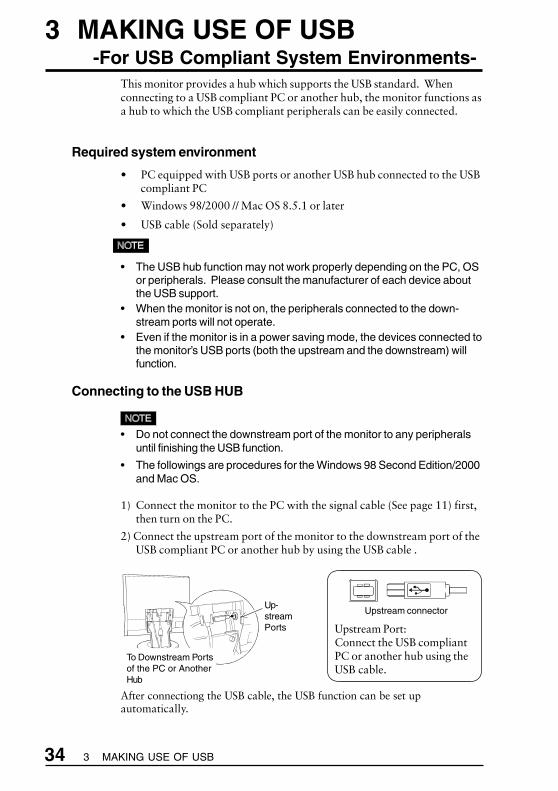
1) Connect the monitor to the PC with the signal cable (See page 11) first,then turn on the PC.
2) Connect the upstream port of the monitor to the downstream port of theUSB compliant PC or another hub by using the USB cable .
After connectiong the USB cable, the USB function can be set upautomatically.
3 MAKING USE OF USB-For USB Compliant System Environments-
Upstream Port:Connect the USB compliantPC or another hub using theUSB cable.
Upstream connectorUp-streamPorts
To Downstream Portsof the PC or AnotherHub

E
35 3 MAKING USE OF USB
3) After setting up, the monitor’s USB hub is available for connecting USBcompliant peripherals to the downstream ports of the monitor.
(Example of connection)
Rear port (Example)
PC
Scanner
Printer
MouseKeyboard
DigitalCamera
USBCable
Monitor
Downstream ports:Connect the cables from USBcompliant peripherals suchas a mouse, keyboard, etc.
Downstream Downstream connector
36 3 MAKING USE OF USB
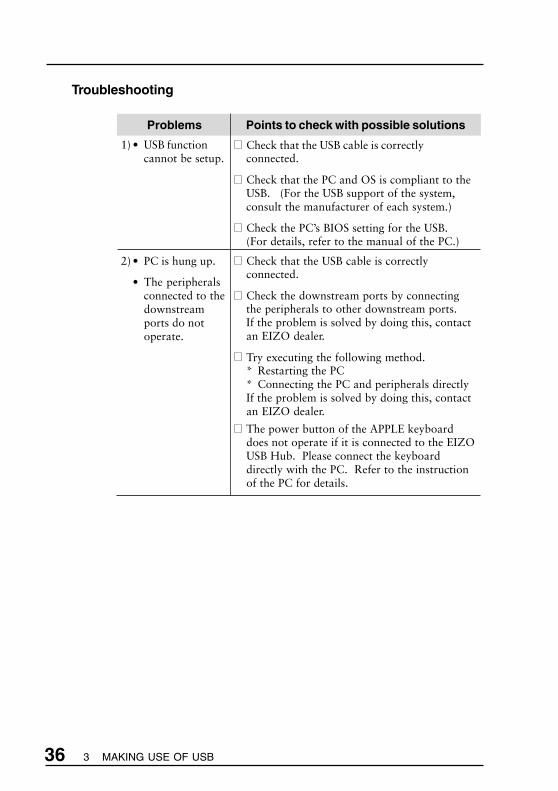
Points to check with possible solutions
Check that the USB cable is correctlyconnected.
Check that the PC and OS is compliant to theUSB. (For the USB support of the system,consult the manufacturer of each system.)
Check the PC’s BIOS setting for the USB.(For details, refer to the manual of the PC.)
Check that the USB cable is correctlyconnected.
Check the downstream ports by connectingthe peripherals to other downstream ports.If the problem is solved by doing this, contactan EIZO dealer.
Try executing the following method.* Restarting the PC* Connecting the PC and peripherals directlyIf the problem is solved by doing this, contactan EIZO dealer.
The power button of the APPLE keyboarddoes not operate if it is connected to the EIZOUSB Hub. Please connect the keyboarddirectly with the PC. Refer to the instructionof the PC for details.
Problems
1) • USB functioncannot be setup.
2) • PC is hung up.
• The peripheralsconnected to thedownstreamports do notoperate.
Troubleshooting

E
37 4 TROUBLESHOOTING
4 TROUBLESHOOTING
Points to check with possible solutions
Check that the power cord is securely connected.
Try pressing a key on the keyboard, or clicking themouse. (The screen-saver software may be active.)
Check brightness and contrast settings. Minimumsettings will cause screen to be blank.
Try pressing the power button. (The off timermay be active.)
Try pressing a key on the keyboard, or clicking themouse. (The screen-saver software may be active.)
If the problem persists, switch off the monitormain power for a few minutes, then switch it backon and try again.
Check that the PC is switched ON.
Check that the signal cable is properly connectedto the graphics board or PC.
Check that the graphics board is correctly insertedin the PC.
Switch the signal input by pushing the input signalselection button on the front control panel.
For Windows 95/98 users, install the “Monitorinformation file” in the utility disk.
Problems
1) Indicator status: OFF
2) Indicator status: GREEN
3) Indicator status: YELLOW (flashing)
4) Indicator status: YELLOW
5) “No signal detected” errormessage appears.
This page presents problems that can be corrected by the user. If aproblem persists even after applying the suggested remedies, contact anEIZO dealer.
No picture
• Whenever an error signal message appears, the signal frequency will be displayedin red.
• Error messages will remain on the screen for 30 seconds, and then disappear. Anerror message may not appear at all if the signal frequency is extremely high orextremely low.

38 4 TROUBLESHOOTING
Points to check with possible solutions
Use the graphics board’s utility software to changethe frequency setting. (Refer to the manual of thegraphics board.)
For Windows 95 users (OSR 2.0 or newer)/98,restart the PC in a safe mode and change thefrequency at the "Display" setting in the PC.
Adjust the image position using the “Position” iconin the ScreenManager “Screen” menu. See page 23.If the problem persists, use the graphics board'sutility software to change the display position ifavailable. (It may be called “back-porch”.)
Decrease the vertical bars using the “Clock” icon inthe ScreenManager “Screen” menu. See page 22.
Adjust the blurred lines using “Smoothing” adjustment. Please refer to the page 25.
This happens when both composite (X-OR) inputsignal and separate vertical synchronizing signal areinput. Please select either of those.
Imaging problems
Problems
1) “Out of range” errormessage appears.
(Example)
2) Display position is incorrect.
3) Vertical bars of distortionappear.
4) Letters and lines appearblurred.
5) Distortion appears like thefigure below.
• Whenever an error signal message appears, the signal frequency will be displayed inred.

E
39 4 TROUBLESHOOTING
Problems
6) Horizontal bars of distortionappear.
7) The screen is too bright or toodark.
8) Afterimages appear.
9) Fingerprints remain on thescreen.
10)The screen has defectivepixels (e.g. slightly light ordark).
Other
Problems
1) The utility disk is unable to beopened (for Macintosh only).
2) • The Enter button does notoperate.
• The Auto adjustmentbutton does not operate.
Points to check with possible solutions
Decrease the horizontal bars using the “Phase” iconin the ScreenManager “Screen” menu. See page 23.
Adjust the contrast and brightness using theScreenManager’s Screen menu. See page 24.
(The backlight of the LCD monitor has a fixed lifespan. When the screen becomes dark or begins toflicker, please contact your dealer.)
When the screen image has been changed afterdisplaying the same image for a long period,afterimage may appear. Use the Off Timer functionand avoid keeping the screen on all the time.
·L660 Open a black pattern window and keep themonitor on for a while.
·L661 Open a white pattern window and keep themonitor on for a while.
·L680 Open a black pattern window and keep themonitor on for a while.
Leaving the screen white may solve the problem.
This is due to the characteristics of the panel itself,and not the LCD product.
Points to check with possible solutions
Some PCs without PC-Exchange do not allow theutility disk to be opened. Please set the desktoppattern to ever-other-dot before adjustment. Seepage 21.
The adjustment lock is probably on. To unlock:switch the LCD monitor off. Then, while pressingthe Auto adjustment button switch the power on.See page 18.

40 4 TROUBLESHOOTING
Problems
3) The Auto adjustment buttondoes not work properly.
4) Frequency does not changeafter installing “Monitorinformation file” in theattached utility disk onWindows 95/98.
Points to check with possible solutions
The Auto adjustment function is intended for use onMacintosh and IBM compatibles PCs runningWindows. It may not work properly if either ofthe following applies.- You are running an AT-compatible PC on MS-
DOS (not Windows).- The background color for the “wallpaper” or
“desktop” pattern is set to black.
Some signals from the graphics boards may notfunction properly. Follow the adjustmentprocedure on page 20, adjust step by step usingthe “Screen” menu.
Use the graphics board’s utility software to changethe input signal frequency.
• For problems with USB function, refer to the troubleshooting on page 36.

E
415 CLEANING
WARNING
• Keep liquids away from the monitor.
Spillage into the cabinet may result in fire, electric shock, orequipment damage.
If an object or liquid falls/spills into the cabinet, unplug themonitor immediately. Have the unit checked by a qualifiedservice engineer before using it again.
CAUTION
• To ensure safety, always unplug the monitor beforecleaning it.
Cleaning the monitor while it is plugged into a power outletmay result in electric shock.
• Periodically clean the area around the plug.
Buildup of dust, water, or oil on the plug may result in fire.
• Dust accumulation within the monitor may result in fire orequipment failure.
Please keep the monitor in a dust-free environment.
• Never use thinner, benzene, alcohol (ethanol, methanol, orisopropyl alcohol), abrasive cleaners, or other strongsolvents, as these may cause damage to the cabinet orLCD.
Periodic cleaning is recommended to keep the monitor lookingnew and to prolong its operational lifetime. Clean the cabinetand LCD panel as follows.
Cabinet
To remove stains, wipe the cabinet with a soft, lightly moistenedcloth using a mild detergent. Do not spray wax or cleanerdirectly onto the cabinet.
LCD panel
The LCD surface can be cleaned with a soft cloth, such as cottonor lens paper.
If necessary, stubborn stains can be removed by moistening partof a cloth with water to enhance its cleaning power.
5 CLEANING
42 6 SPECIFICATIONS
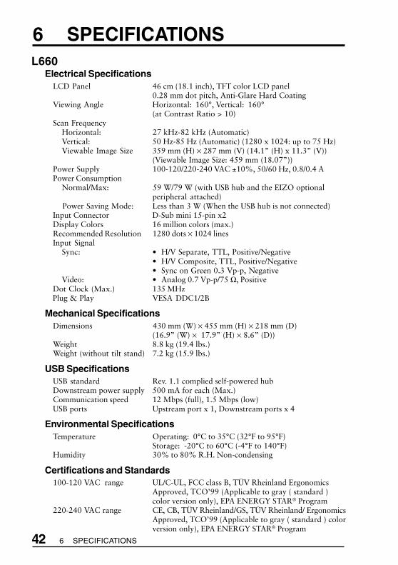
6 SPECIFICATIONSL660
Electrical SpecificationsLCD Panel 46 cm (18.1 inch), TFT color LCD panel
0.28 mm dot pitch, Anti-Glare Hard CoatingViewing Angle Horizontal: 160°, Vertical: 160°
(at Contrast Ratio > 10)Scan Frequency
Horizontal: 27 kHz-82 kHz (Automatic)Vertical: 50 Hz-85 Hz (Automatic) (1280 x 1024: up to 75 Hz)Viewable Image Size 359 mm (H) × 287 mm (V) (14.1” (H) x 11.3” (V))
(Viewable Image Size: 459 mm (18.07”))Power Supply 100-120/220-240 VAC ±10%, 50/60 Hz, 0.8/0.4 APower Consumption
Normal/Max: 59 W/79 W (with USB hub and the EIZO optionalperipheral attached)
Power Saving Mode: Less than 3 W (When the USB hub is not connected)Input Connector D-Sub mini 15-pin x2Display Colors 16 million colors (max.)Recommended Resolution 1280 dots × 1024 linesInput Signal
Sync: • H/V Separate, TTL, Positive/Negative• H/V Composite, TTL, Positive/Negative• Sync on Green 0.3 Vp-p, Negative
Video: • Analog 0.7 Vp-p/75 Ω, PositiveDot Clock (Max.) 135 MHzPlug & Play VESA DDC1/2B
Mechanical SpecificationsDimensions 430 mm (W) × 455 mm (H) × 218 mm (D)
(16.9” (W) × 17.9” (H) × 8.6” (D))Weight 8.8 kg (19.4 lbs.)Weight (without tilt stand) 7.2 kg (15.9 lbs.)
USB SpecificationsUSB standard Rev. 1.1 complied self-powered hubDownstream power supply 500 mA for each (Max.)Communication speed 12 Mbps (full), 1.5 Mbps (low)USB ports Upstream port x 1, Downstream ports x 4
Environmental SpecificationsTemperature Operating: 0°C to 35°C (32°F to 95°F)
Storage: -20°C to 60°C (-4°F to 140°F)Humidity 30% to 80% R.H. Non-condensing
Certifications and Standards100-120 VAC range UL/C-UL, FCC class B, TÜV Rheinland Ergonomics
Approved, TCO’99 (Applicable to gray ( standard )color version only), EPA ENERGY STAR® Program
220-240 VAC range CE, CB, TÜV Rheinland/GS, TÜV Rheinland/ ErgonomicsApproved, TCO’99 (Applicable to gray ( standard ) colorversion only), EPA ENERGY STAR® Program

E
436 SPECIFICATIONS
L661Electrical Specifications
LCD Panel 46 cm (18.1 inch), TFT color LCD panel0.28 mm dot pitch, Anti-Glare Hard Coating
Viewing Angle Horizontal: 140°, Vertical: 140°(at Contrast Ratio > 5)
Scan FrequencyHorizontal: 27 kHz-82 kHz (Automatic)Vertical: 50 Hz-85 Hz (Automatic) (1280 x 1024: up to 75 Hz)Viewable Image Size 359mm (H) × 287 mm (V) (14.1” (H) × 11.3”(V))
(Viewable Image Size: 459 mm (18.07”))Power Supply 100-120/220-240 VAC ±10%, 50/60 Hz, 0.7/0.4 APower Consumption
Normal/Max: 47 W/69 W (with USB hub and the EIZO optionalperipheral attached)
Power Saving Mode: Less than 3 W (When the USB hub is not connected)Input Connector D-Sub mini 15-pin x 2Display Colors 16 million colors (max.)Recommended Resolution 1280 dots × 1024 linesInput Signal
Sync: • H/V Separate, TTL, Positive/Negative• H/V Composite, TTL, Positive/Negative• Sync on Green 0.3 Vp-p, Negative
Video: • Analog 0.7 Vp-p/75 Ω, PositiveDot Clock (Max.) 135 MHzPlug & Play VESA DDC1/2B
Mechanical SpecificationsDimensions 430 mm (W) × 455 mm (H) × 218 mm (D)
(16.9” (W) × 17.9” (H) × 8.6” (D))Weight 8.8 kg (19.4 lbs.)Weight (without tilt stand) 7.2 kg (15.9 lbs.)
USB SpecificationsUSB standard Rev. 1.1 complied self-powered hubDownstream power supply 500 mA for each (Max.)Communication speed 12 Mbps (full), 1.5 Mbps (low)USB ports Upstream port x 1, Downstream ports x 4
Environmental SpecificationsTemperature Operating: 0°C to 35°C (32°F to 95°F)
Storage: -20°C to 60°C (-4°F to 140°F)Humidity 30% to 80% R.H. Non-condensing
Certifications and Standards100-120 VAC range UL/C-UL, FCC class B, TÜV Rheinland Ergonomics
Approved, TCO’99 (Applicable to gray ( standard )color version only), EPA ENERGY STAR® Program
220-240 VAC range CE, CB, TÜV Rheinland/GS, TÜV Rheinland/ ErgonomicsApproved, TCO’99 (Applicable to gray ( standard ) colorversion only), EPA ENERGY STAR® Program
44 6 SPECIFICATIONS
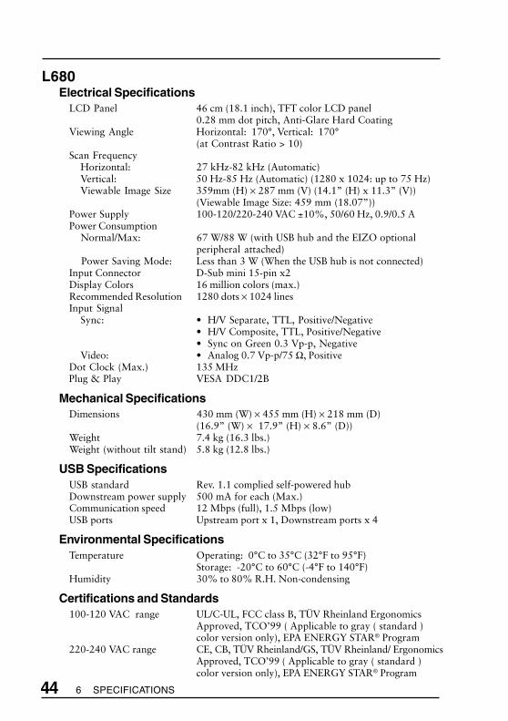
L680Electrical Specifications
LCD Panel 46 cm (18.1 inch), TFT color LCD panel0.28 mm dot pitch, Anti-Glare Hard Coating
Viewing Angle Horizontal: 170°, Vertical: 170°(at Contrast Ratio > 10)
Scan FrequencyHorizontal: 27 kHz-82 kHz (Automatic)Vertical: 50 Hz-85 Hz (Automatic) (1280 x 1024: up to 75 Hz)Viewable Image Size 359mm (H) × 287 mm (V) (14.1” (H) x 11.3” (V))
(Viewable Image Size: 459 mm (18.07”))Power Supply 100-120/220-240 VAC ±10%, 50/60 Hz, 0.9/0.5 APower Consumption
Normal/Max: 67 W/88 W (with USB hub and the EIZO optionalperipheral attached)
Power Saving Mode: Less than 3 W (When the USB hub is not connected)Input Connector D-Sub mini 15-pin x2Display Colors 16 million colors (max.)Recommended Resolution 1280 dots × 1024 linesInput Signal
Sync: • H/V Separate, TTL, Positive/Negative• H/V Composite, TTL, Positive/Negative• Sync on Green 0.3 Vp-p, Negative
Video: • Analog 0.7 Vp-p/75 Ω, PositiveDot Clock (Max.) 135 MHzPlug & Play VESA DDC1/2B
Mechanical SpecificationsDimensions 430 mm (W) × 455 mm (H) × 218 mm (D)
(16.9” (W) × 17.9” (H) × 8.6” (D))Weight 7.4 kg (16.3 lbs.)Weight (without tilt stand) 5.8 kg (12.8 lbs.)
USB SpecificationsUSB standard Rev. 1.1 complied self-powered hubDownstream power supply 500 mA for each (Max.)Communication speed 12 Mbps (full), 1.5 Mbps (low)USB ports Upstream port x 1, Downstream ports x 4
Environmental SpecificationsTemperature Operating: 0°C to 35°C (32°F to 95°F)
Storage: -20°C to 60°C (-4°F to 140°F)Humidity 30% to 80% R.H. Non-condensing
Certifications and Standards100-120 VAC range UL/C-UL, FCC class B, TÜV Rheinland Ergonomics
Approved, TCO’99 ( Applicable to gray ( standard )color version only), EPA ENERGY STAR® Program
220-240 VAC range CE, CB, TÜV Rheinland/GS, TÜV Rheinland/ ErgonomicsApproved, TCO’99 ( Applicable to gray ( standard )color version only), EPA ENERGY STAR® Program

ii APPENDIX
APPENDIXPin AssignmentPin-BelegungAffectation des Broches
2 x D-Sub mini 15 pin connectors
USB ports
Upstream Downstream No. Signal Comments
1 VCC Cable power
2 - Data Serial data
3 + Data Serial data
(Series B connector) (Series A connector) 4 Ground Cable Ground
Pin No. Signal Pin No. Signal
1 Red video 9 No pin
2 Green video/ 10 Ground
Composite 11 (shorted)
3 Blue video 12 Data
4 Ground 13 H. Sync or H./V.
5 No pin Composite sync
6 Red ground 14 V. Sync
7 Green ground 15 Clock
8 Blue ground
Green video/Green video
Composite Sync
H. Sync/H. V.Composite Sync
GroundShorted
iii APPENDIX
A
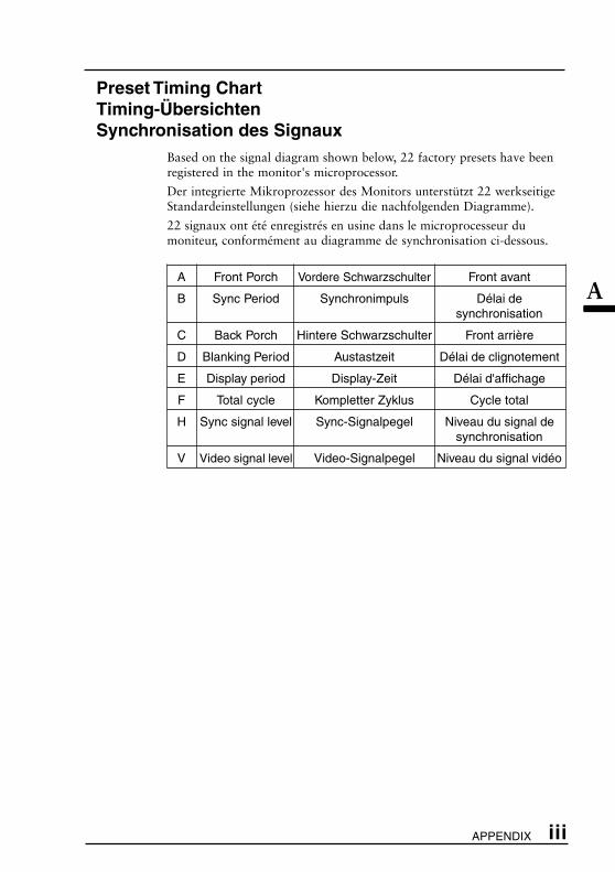
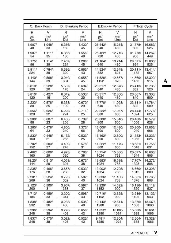
Preset Timing ChartTiming-ÜbersichtenSynchronisation des Signaux
Based on the signal diagram shown below, 22 factory presets have beenregistered in the monitor's microprocessor.
Der integrierte Mikroprozessor des Monitors unterstützt 22 werkseitigeStandardeinstellungen (siehe hierzu die nachfolgenden Diagramme).
22 signaux ont été enregistrés en usine dans le microprocesseur dumoniteur, conformément au diagramme de synchronisation ci-dessous.
A Front Porch Vordere Schwarzschulter Front avant
B Sync Period Synchronimpuls Délai desynchronisation
C Back Porch Hintere Schwarzschulter Front arrière
D Blanking Period Austastzeit Délai de clignotement
E Display period Display-Zeit Délai d'affichage
F Total cycle Kompletter Zyklus Cycle total
H Sync signal level Sync-Signalpegel Niveau du signal desynchronisation
V Video signal level Video-Signalpegel Niveau du signal vidéo

iv APPENDIX
Mode Dot Clock Frequencies A: Front Porch B: Sync Period
MHz H V H V H VkHz Hz µs/ ms/ µs/ ms/
Dot Line Dot Line
VGA 0.636/ 0.318/ 3.813/ 0.054/640 x 480 25.175 31.468 59.941 16 10 96 2
VGA 0.636/ 0.381/ 3.813/ 0.064/720 x 400 28.322 31.468 70.087 18 12 108 2
Macintosh 2.116/ 0.086/ 2.116/ 0.086/640 x 480 30.24 35.00 66.67 64 3 64 3
Macintosh 0.559/ 0.020/ 1.117/ 0.060/832 x 624 57.28 49.73 74.55 32 1 64 3
Macintosh 0.320/ 0.044/ 1.280/ 0.044/1152 x 870 100.0 68.68 75.06 32 3 128 3
VESA 0.508/ 0.026/ 1.270/ 0.079/640 x 480 31.5 37.86 72.81 16 1 40 3
VESA 0.508/ 0.027/ 2.032/ 0.080/640 x 480 31.5 37.5 75.00 16 1 67 3
VESA 1.556/ 0.023/ 1.556/ 0.069/640 x 480 36.0 43.27 85.01 56 1 56 3
VESA 0.667/ 0.028/ 2.000/ 0.057/800 x 600 36.0 35.16 56.25 24 1 72 2
VESA 1.000/ 0.026/ 3.200/ 0.106/800 x 600 40.0 37.88 60.32 40 1 128 4
VESA 1.120/ 0.770/ 2.400/ 0.125/800 x 600 50.0 48.08 72.19 56 37 120 6
VESA 0.323/ 0.021/ 1.616/ 0.064/800 x 600 49.5 46.88 75.00 16 1 80 3
VESA 0.569/ 0.019/ 1.138/ 0.056/800 x 600 56.25 53.674 85.061 32 1 64 3
VESA 0.369/ 0.062/ 2.092/ 0.124/1024 x 768 65.0 48.36 60.00 24 3 136 6
VESA 0.320/ 0.053/ 1.813/ 0.106/1024 x 768 75.0 56.48 70.07 24 3 136 6
VESA 0.203/ 0.017/ 1.219/ 0.050/1024 x 768 78.75 60.02 75.03 16 1 96 3
VESA 0.508/ 0.015/ 1.016/ 0.044/1024 x 768 94.5 68.68 85.0 48 1 96 3
Workstation 0.425/ 0.032/ 1.359/ 0.065/1152 x 900 94.2 61.974 66.141 40 2 128 4
Workstation 0.223/ 0.028/ 1.265/ 0.111/1152 x 900 107.50 71.858 76.202 24 2 136 8
Macintosh 0.190/ 0.013/ 1.204/ 0.040/1280 x 960 126.2 74.763 74.763 24 1 152 3
VESA 0.444/ 0.016/ 1.037/ 0.047/1280 x 1024 108.0 63.98 60.02 48 1 112 3
VESA 0.119/ 0.013/ 1.067/ 0.038/1280 x 1024 135.0 79.97 75.02 16 1 144 3
v APPENDIX
A
C: Back Porch D: Blanking Period E:Display Period F:Total Cycle
H V H V H V H Vµs/ ms/ µs/ ms/ µs/ ms/ µs/ ms/Dot Line Dot Line Dot Line Dot Line
1.907/ 1.048/ 6.356/ 1.430/ 25.442/ 15.254/ 31.778/ 16.683/48 33 160 45 640 480 800 525
1.907/ 1.111/ 6.356/ 1.556/ 25.422/ 12.712/ 31.778/ 14.267/54 35 180 49 720 400 900 449
3.175/ 1.114/ 7.407/ 1.286/ 21.164/ 13.714/ 28.571/ 15.000/96 39 224 45 640 480 864 525
3.911/ 0.784/ 5.586/ 0.865/ 14.524/ 12.549/ 20.111/ 13.414/224 39 320 43 832 624 1152 667
1.440/ 0.568/ 3.040/ 0.655/ 11.520/ 12.667/ 14.560/ 13.322/144 39 304 45 1152 870 1456 915
3.810/ 0.528/ 5.587/ 0.634/ 20.317/ 12.678/ 26.413/ 13.735/120 20 176 24 640 480 832 520
3.810/ 0.427/ 6.349/ 0.533/ 20.317/ 12.800/ 26.667/ 13.333/120 16 200 20 640 480 840 500
2.222/ 0.578/ 5.333/ 0.670/ 17.778/ 11.093/ 23.111/ 11.764/80 25 192 29 640 480 832 500
3.556/ 0.626/ 6.222/ 0.711/ 22.222/ 17.067/ 28.444/ 17.778/128 22 224 25 800 600 1024 625
2.200/ 0.607/ 6.400/ 0.739/ 20.000/ 15.840/ 26.400/ 16.579/88 23 256 28 800 600 1056 628
1.280/ 0.478/ 4.800/ 1.373/ 16.000/ 12.480/ 20.800/ 13.853/64 23 240 66 800 600 1040 666
3.232/ 0.448/ 5.172/ 0.533/ 16.162/ 12.800/ 21.333/ 13.333/160 21 256 25 800 600 1056 625
2.702/ 0.503/ 4.409/ 0.578/ 14.222/ 11.179/ 18.631/ 11.756/152 27 248 31 800 600 1048 631
2.462/ 0.600/ 4.923/ 0.786/ 15.754/ 15.880/ 20.677/ 16.666/160 29 320 38 1024 768 1344 806
19.20/ 0.513/ 4.053/ 0.673/ 13.653/ 16.599/ 17.707/ 14.272/144 29 304 38 1024 768 1328 806
2.235/ 0.466/ 3.657/ 0.533/ 13.003/ 12.795/ 16.660/ 13.328/176 28 288 32 1024 768 1312 800
2.201/ 0.524/ 3.725/ 0.582/ 10.836/ 11.183/ 14.561/ 11.765/208 36 352 40 1024 768 1376 808
2.123/ 0.500/ 3.907/ 0.597/ 12.229/ 14.522/ 16.136/ 15.119/200 31 368 37 1152 900 1520 937
1.712/ 0.459/ 3.200/ 0.598/ 10.716/ 12.525/ 13.916/ 13.123/184 33 344 43 1152 900 1496 943
1.838/ 0.482/ 3.233/ 0.535/ 10.143/ 12.841/ 13.376/ 13./376232 36 408 40 1280 960 1688 1000
2.296/ 0.594/ 3.778/ 0.656/ 11.852/ 16.005 15.630/ 16.661/248 38 408 42 1280 1024 1688 1066
1.837/ 0.475/ 3.022/ 0.525/ 9.481/ 12.804/ 12.504/ 13.329/248 38 408 42 1280 1024 1688 1066

vi APPENDIX
FRONT VIEWVORDERANSICHTVUE DE FACE
SIDE VIEWSEITENANSICHTVUE DE COTE
TOP VIEWDRAUFSICHTVUE D'EN HAUT
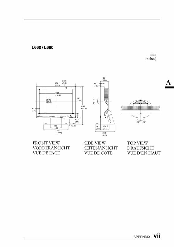
DimensionsAbmessungenDimensions
L661
mm(inches)
289.2(11.4)
34.5(1.4)
54.9(2.2)
120(4.7)
270(10.6)
20.5(0.8)
22°
3°
58(2.3)
94.9(3.7)
218(8.6)
30.9(1.2)
25° 25°
87(3.4)
27(1.1)
430(16.9)
361(14.2)
375(14.8)
455(17.9)
vii APPENDIX
A
L660 / L680
mm(inches)
289.2(11.4)
34.5(1.4)
49.9(2.0)
120(4.7)
270(10.6)
20.5(0.8)
22°
3°
48(1.9)
104.9(4.1)
218(8.6)
35.9(1.4)
25° 25°
97(3.8)
37(1.5)
430(16.9)
361(14.2)
375(14.8)
455(17.9)
FRONT VIEWVORDERANSICHTVUE DE FACE
SIDE VIEWSEITENANSICHTVUE DE COTE
TOP VIEWDRAUFSICHTVUE D'EN HAUT

Congratulations!You have just purchased a TCO’99 approved and labelled product! Your choice has providedyou with a product developed for professional use. Your purchase has also contributed toreducing the burden on the environment and also to the further development of environmen-tally adapted electronics products.
Why do we have environmentally labelled computers?In many countries, environmental labelling has become an established method for
encouraging the adaptation of goods and services to the environment. The main problem,as far as computers and other electronics equipment are concerned, is that environmen-tally harmful substances are used both in the products and during their manufacture. Sinceit is not so far possible to satisfactorily recycle the majority of electronics equipment, mostof these potentially damaging substances sooner or later enter nature.
There are also other characteristics of a computer, such as energy consumption levels,that are important from the viewpoints of both the work (internal) and natural (external)environments. Since all methods of electricity generation have a negative effect on theenvironment (e.g. acidic and climate-influencing emissions, radioactive waste), it is vitalto save energy. Electronics equipment in offices is often left running continuously andthereby consumes a lot of energy.
What does labelling involve?This product meets the requirements for the TCO’99 scheme which provides for
international and environmental labelling of personal computers. The labelling schemewas developed as a joint effort by the TCO (The Swedish Confederation of ProfessionalEmployees), Svenska Naturskyddsforeningen (The Swedish Society for Nature Conserva-tion) and Statens Energimyndighet (The Swedish National Energy Administration).
Approval requirements cover a wide range of issues: environment, ergonomics, usability,emission of electric and magnetic fields, energy consumption and electrical and fire safety.
The environmental demands impose restrictions on the presence and use of heavymetals, brominated and chlorinated flame retardants, CFCs (freons) and chlorinatedsolvents, among other things. The product must be prepared for recycling and themanufacturer is obliged to have an environmental policy which must be adhered to ineach country where the company implements its operational policy.
The energy requirements include a demand that the computer and/or display, after acertain period of inactivity, shall reduce its power consumption to a lower level in one ormore stages. The length of time to reactivate the computer shall be reasonable for the user.
Labelled products must meet strict environmental demands, for example, in respect ofthe reduction of electric and magnetic fields, physical and visual ergonomics and goodusability.
Below you will find a brief summary of the environmental requirements met by thisproduct. The complete environmental criteria document may be ordered from:
TCO Development
SE-114 94 Stockholm, SwedenFax: +46 8 782 92 07Email (Internet): [email protected] information regarding TCO’99 approved and labelled products may also beobtained via the Internet, using the address: http://www.tco-info.com/
Applicable to gray( standard ) colorversion only

Environmental requirements
Flame retardantsFlame retardants are present in printed circuit boards, cables, wires, casings and
housings. Their purpose is to prevent, or at least to delay the spread of fire. Up to 30%of the plastic in a computer casing can consist of flame retardant substances. Mostflame retardants contain bromine or chloride, and those flame retardants are chemicallyrelated to another group of environmental toxins, PCBs. Both the flame retardantscontaining bromine or chloride and the PCBs are suspected of giving rise to severehealth effects, including reproductive damage in fish-eating birds and mammals, due tothe bio-accumulative* processes. Flame retardants have been found in human blood andresearchers fear that disturbances in foetus development may occur.
The relevant TCO’99 demand requires that plastic components weighing more than25 grams must not contain flame retardants with organically bound bromine orchlorine. Flame retardants are allowed in the printed circuit boards since no substitutesare available.
Cadmium**Cadmium is present in rechargeable batteries and in the colour-generating layers of
certain computer displays. Cadmium damages the nervous system and is toxic in highdoses. The relevant TCO’99 requirement states that batteries, the colour-generatinglayers of display screens and the electrical or electronics components must not containany cadmium.
Mercury**Mercury is sometimes found in batteries, relays and switches. It damages the nervous
system and is toxic in high doses. The relevant TCO’99 requirement states that batteriesmay not contain any mercury. It also demands that mercury is not present in any of theelectrical or electronics components associated with the labelled unit.
CFCs (freons)The relevant TCO’99 requirement states that neither CFCs nor HCFCs may be used
during the manufacture and assembly of the product. CFCs (freons) are sometimes usedfor washing printed circuit boards. CFCs break down ozone and thereby damage theozone layer in the stratosphere, causing increased reception on earth of ultraviolet lightwith e.g. increased risks of skin cancer (malignant melanoma) as a consequence.
Lead**Lead can be found in picture tubes, display screens, solders and capacitors. Lead
damages the nervous system and in higher doses, causes lead poisoning. The relevantTCO’99 requirement permits the inclusion of lead since no replacement has yet beendeveloped.
* Bio-accumulative is defined as substances which accumulate within livingorganisms.** Lead, Cadmium and Mercury are heavy metals which are Bio-accumulative.
Applicable to gray( standard ) colorversion only
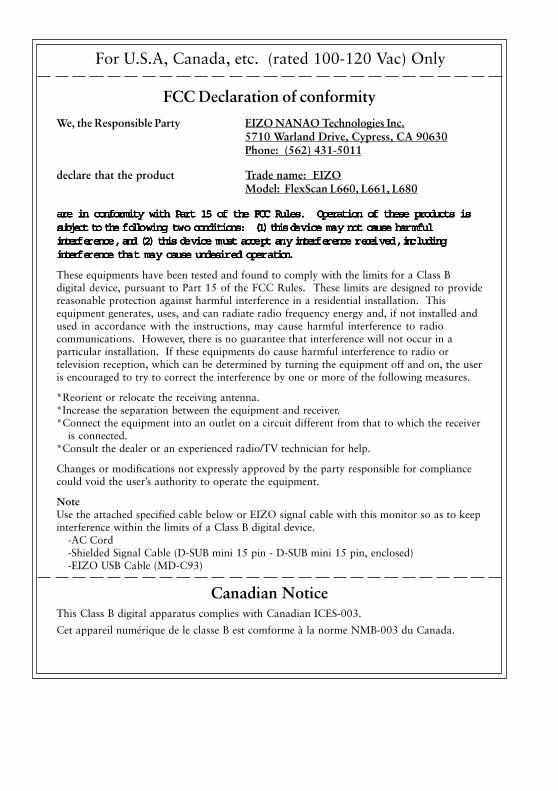
FCC Declaration of conformity
We, the Responsible Party EIZO NANAO Technologies Inc.5710 Warland Drive, Cypress, CA 90630Phone: (562) 431-5011
declare that the product Trade name: EIZOModel: FlexScan L660, L661, L680
are in conformity with Part 15 of the FCC Rules. Operation of these products isare in conformity with Part 15 of the FCC Rules. Operation of these products isare in conformity with Part 15 of the FCC Rules. Operation of these products isare in conformity with Part 15 of the FCC Rules. Operation of these products isare in conformity with Part 15 of the FCC Rules. Operation of these products issubject to the fsubject to the fsubject to the fsubject to the fsubject to the folloolloolloolloollowing twwing twwing twwing twwing two conditions:o conditions:o conditions:o conditions:o conditions: (1) this de (1) this de (1) this de (1) this de (1) this device mavice mavice mavice mavice may not cause hary not cause hary not cause hary not cause hary not cause harmfulmfulmfulmfulmfulinterfinterfinterfinterfinterferererererenceenceenceenceence,,,,, and (2) this de and (2) this de and (2) this de and (2) this de and (2) this device mvice mvice mvice mvice must acceust acceust acceust acceust accept anpt anpt anpt anpt any interfy interfy interfy interfy interferererererence rence rence rence rence receieceieceieceieceivvvvvededededed,,,,, inc inc inc inc includingludingludingludingludinginterfinterfinterfinterfinterferererererence thaence thaence thaence thaence that mat mat mat mat may cause undesiry cause undesiry cause undesiry cause undesiry cause undesired opered opered opered opered operaaaaation.tion.tion.tion.tion.
These equipments have been tested and found to comply with the limits for a Class Bdigital device, pursuant to Part 15 of the FCC Rules. These limits are designed to providereasonable protection against harmful interference in a residential installation. Thisequipment generates, uses, and can radiate radio frequency energy and, if not installed andused in accordance with the instructions, may cause harmful interference to radiocommunications. However, there is no guarantee that interference will not occur in aparticular installation. If these equipments do cause harmful interference to radio ortelevision reception, which can be determined by turning the equipment off and on, the useris encouraged to try to correct the interference by one or more of the following measures.
*Reorient or relocate the receiving antenna.*Increase the separation between the equipment and receiver.*Connect the equipment into an outlet on a circuit different from that to which the receiver
is connected.*Consult the dealer or an experienced radio/TV technician for help.
Changes or modifications not expressly approved by the party responsible for compliancecould void the user’s authority to operate the equipment.
NoteUse the attached specified cable below or EIZO signal cable with this monitor so as to keepinterference within the limits of a Class B digital device.
-AC Cord-Shielded Signal Cable (D-SUB mini 15 pin - D-SUB mini 15 pin, enclosed)-EIZO USB Cable (MD-C93)
Canadian NoticeThis Class B digital apparatus complies with Canadian ICES-003.
Cet appareil numérique de le classe B est comforme à la norme NMB-003 du Canada.
For U.S.A, Canada, etc. (rated 100-120 Vac) Only
Hinweis zur Ergonomie :Dieser Monitor erfüllt die Anforderungen an die Ergonomie nach EK1/59-98, EK1/60-98 mitdem Videosignal, 1280 Punkte x 1024 Zeilen, RGB analog, 0,7 Vp-p und mindestens 75,0 HzBildwiederholfrequenz, (non interlaced).
Weiterhin wird aus ergonomischen Gründen empfohlen, die Grundfarbe Blau nicht auf dunklemUntergrund zu verwenden (schlechte Erkennbarkeit, Augenbelastung bei zu geringemZeichenkontrast.)
Recycle AuskunftDie Rücknahme dieses Produktes nach Nutzungsende übernimmt EIZO in Deutschlandzusammen mit dem Partner von Roll MBB Recycling GmbH.Dort werden die Geräte in ihre Bestandteile zerlegt, die dann der Wiederverwertung zugeführtwerden. Um einen Abholtermin zu vereinbaren und die aktuellen Kosten zu erfahren, benutzenSie bitte folgende Rufnummer: 02153-73 35 00. Weitere Informationen finden Sie auch unterder Internet-Adresse: www.eizo.de.