flexible underground piping manual fueling...installation instruction sheets and manuals can be...
TRANSCRIPT
Flexible Underground
Piping Manual Product Manual * Publication Number: UPM-0001 * Issue Date: 04/28/11
Supercedes: 05/27/09

INDEX
1.0 Introduction2.0 Specifying Flexible Piping3.0 Flexible Piping Connections4.0 Flexible Pipe Accessories5.0 Installer Tools6.0 Pre-Installation Planning7.0 Piping Design Criteria 8.0 Pipe Burial Requirements9.0 Flexible Piping Options
10.0 Installing Duct Conduit11.0 Tank Sump Plumbing Trees12.0 Dispenser Sump Pipe Connections13.0 Flexible Pipe Fabrication14.0 Piping Connections15.0 Test Boots16.0 Tubing Assemblies17.0 Flexible Vent Piping18.0 Testing & Filling Supply Pipe19.0 Periodic Line Leak Detection20.0 Interstitial Integrity Testing21.0 FlexWorks System Maintenance22.0 Periodic Interstitial Testing23.0 Problems24.0 Guide Specifications25.0 Storage and Handling
1.0 INTRODUCTIONThe FlexWorks family of products byOPW-FCS offers a full lineof flexible piping and pipeconnection products to providean environmentally safe means ofconveying fuels from undergroundstorage tanks to above ground fueldispensers. The variety of pipingand pipe connections availableallows for a wide range of piperouting options to meet any site design requirements.Flexible piping has proven to be safer than conventionalrigid piping which requires numerous connection joints anddirectional fittings. In addition, flexible piping has proven tobe considerably faster to install and more cost effective thanrigid piping
1.1 General InformationThis product manual contains useful information aboutall types of flexible piping products and their associatedconnections, accessories and installer tools. It is required thatthis manual be read prior to specifying and installing flexiblepiping. The installation practices shall comply with theseinstallation instructions contained within this product manualin order for the piping system warrantyto be valid. IMPORTANT: OPW-FCS system componentsmay only be installed and serviced by a factory trainedand currently certified installer in order for the productwarranty to be valid. The use of non-certified personnelor any deviations from these written procedures couldresult in damage or leakage of the system and void theproduct warranty. Contact OPW-FCS’s Customer ServiceDepartment for more information at 866-547-1816.
1.2 Certifications and ApprovalsEach of OPW-FCS’s flexible piping systems carry variousglobal approvals based on the individual construction of eachtype of pipe.
1.2.1. UL Listings
FlexWorks double wall piping is listedwith Underwriter’s Laboratories (UL®)under file #MH16678 and labeled asfollows: Motor Vehicle Fuels, High BlendFuels, Concentrated Fuels and Aviationand Marine.
UL Listed FuelsBelow are the listed fuels that have been tested underUL 971 and are warranted for use with the FlexWorks pipingsystem.
1
IMPORTANT INFORMATION - FOLLOW ALL INSTRUCTIONSPlease contact your OPW-FCS sales representative or OPW-FCScustomer service representative at 1-800-422-2525 for OPW-FCSproducts installation procedures. All OPW-FCS literature includinginstallation instruction sheets and manuals can be accessedfrom the OPW-FCS website at: www.opwglobal.com.
The use of non-qualified personnel or any deviations from theserecommended procedures could result in damage or leakageof the system.
Manual Abbreviations:PS = Integral Primary/Secondary PipeNV = Normal VentVR = Vapor RecoveryPP = Petroleum ProductsPri = PrimarySec = SecondaryWP = Working PressurePC = Primary Carrier PipeMV = Motor Vehicle Fuels
IMPORTANT INFORMATIONFOLLOW ALL INSTRUCTIONS
Flexible Underground Piping Manual

Motor Vehicle Fuels100% ASTM Reference Fuel No. 2100% ASTM Reference Fuel C85% Reference Fuel C – 15% MTBE70% Reference Fuel C – 30% Ethanol85% Reference Fuel C – 15% Methanol
High Blend Fuels50% Reference Fuel C - 50% Methanol50% Reference Fuel C - 50% Ethanol
Concentrated Fuels100% Methanol100% Ehtanol100% Toluene
Aviation and Marine Fuels100% Premium Leaded Gas100% Kerosene
WARNING: FlexWorks piping is not warranted forabove ground transmission of flammable liquids dueto the possible exposure to fire.
1.3 Piping ApplicationsOPW-FCS’s flexible supply piping can be direct buriedunderground or installed inside a flexible conduit.
• Pressure System Supply Piping • Vent Piping• Suction System Supply Piping • Remote Fill Lines• *Marina Supply Piping
*Properly designed applications, such as under dock marinaapplications may be allowed with special approval and war-ranty restrictions. Other above ground applications containingflammables must have prior written approval and authorizationfrom OPW-FCS for warranty coverage. All installation practicesshall comply with the installation instructions contained withinthis and other OPW-FCS product manuals.
WARNING: Flex piping is not warranted for above groundtransmission of flammable liquids due to the possible exposureto fire.
1.4 Operating Pressures and TemperaturesOPW-FCS flexible piping and its associated fitting systems have aminimum five to one (5:1) safety factor from maximum ratedoperating pressure for the primary pipe. The product fluidstransferred should not exceed the maximum operating pressuresindicated on each pipe size. For suction systems the pipe iscapable of withstanding 29” mercury vacuum. The maximumtemperature rating of OPW FCS’s flexible piping is 125°F(52°C).
Pipe Size Maximum Working Pressure Rating3/4” 145 psi1” 125 psi1-1/2” 100 psi2” 75 psi3” 75 psi
1.5 Warranted FuelsWarranted fuels are listed as follows: • Gasoline • Methanol • Kerosene • Jet “A”• Gasohol • Alcohol fuels • Diesel Fuels• Ethanol • Av-gas • Motor Oils
Contact OPW-FCS for chemical compatibility of fluids not listed above.
1.6 Pipe PackagingOPW-FCS’s flexible piping systemsare available in a variety of pipingdiameters on continuous rolls andpackaged in easy to handle protectivecartons and reels. Refer to the OPW-FCS Product Price List for pipediametersand packaging specifications.
CAUTION: Do not use knives or razor bladesto open carton as damage to piping could occur.
2.0 SPECIFYING FLEXIBLE PIPINGOPW-FCS’s flexible piping systems offers a variety of pipingoptions for underground fuel delivery applications. Prior tospecifying the type of piping required, read section 6 of thismanual entitled “Pre-Installation Planning”.
2.1 Flex Supply PipingFlexWorks flexible supply piping is designed for direct burialas well as indirect burial within flexible ducting for futurereplacement capabilities. OPW-FCS’s supply piping is totallybonded multi-layer composite construction. The inner-mostbarrier layer is smooth, which enhances hydraulic flowefficiency, and is virtually impervious to gasoline, alcoholblends and a wide variety of other fuels and chemicals. Theexterior of the pipe also has a barrier layer to protect theouter wall of the pipe from chemical and microbial attack.OPW-FCS’s flexible supply piping is available in double wallin continuous lengths.
2.2 FlexWorks Double PipingA UL listed double wall flexible supply piping system that isdesigned for installation within Access piping. The outercontainment jacket includes inner stand-off ribs to create asmall interstitial space which allows for optimum fluidmigration, continuous monitoring and easy periodic testing.This piping features an enhanced construction that meets thenew UL971 standard.
2.3 Access PipeAccess Pipe is a large diametercorrugated flexible piping that addsadditional protection to OPW-FCS’sflexible piping and allows the pipeto beremoved and replaced withoutexcavation. Made of high densitypolyethylene, this corrugated tube isstrong enough to withstand H-20loading requirements when properlyburied and thick enough to minimizedamage from shipping and jobsite handling. Access Pipecan accommodate the 3/4 “, 1”, 1-1/2”, 2” and 3” Flex supplypipe.
2
Flexible Underground Piping Manual
3.0 FLEX PIPING CONNECTIONSOPW-FCS offers three types of piping connection systems foruse with their flexible piping systems. These three differentpiping connections can accommodate a wide variety of pipingdesigns, layouts and installation applications.
Coax Couplings & FittingsThese piping connections are made of a combination of glassreinforced plastic and stainless steel featuring a double walldesign. Coax fittings require the use of the Flex CouplingMachine to install the pipe couplings.
Swivel Couplings & FittingsThese piping connections are made of stainless and protectedsteel featuring a swivel nut connection with a Viton gasket seal.Swivel fittings require the use of the FlexCoupling Machine to install the pipecouplings.
3.1 Coax Couplings & FittingsCoax couplings & fittings are a doublewall design and are used tointerconnect FlexWorks piping. TheseUL® listed composite couplings andfittings permit the entire flexible pipingsystem, including riser pipesto be secondarily contained, tested and monitored. The coaxcouplings & fittings are available in 1-1/2” and 2” sizes.
3.1.1 Coax Pipe Couplings These couplings provide a means ofconnection from OPW-FCS’s flexiblepiping to coax fittings and adapters.Coaxial pipe couplings attach to aflexible pipe section using the OPW-FCS Coupling Machine. Each couplingassembly includes a stainless steelinsert with two O-rings, ferrule with one O-ring, and a swivelnut. Available for both single wall and double wall applications.
NOTE: Coax couplings require a different face plate tobe used with OPW-FCS’s coupling machine than isused with the swivel couplings.
3.1.2 Coax Pipe Adapters
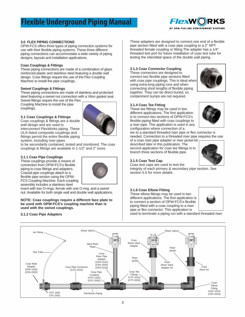
Test Tube
FlexWorks Piping
Air Fitting
Coax MaleAdapter
(CPA-1520)(CPA-2020)
Steel RiserPipes
Coax PipeCoupling
(CPC-1502)(CPC-2002)
Coax TeeFittings
(CTF-1515)(CTF-2020)
Shear Valves
Coax Shear Valve
Adapter
Coax Pipe Connector(CCC-1515)
Coax ElbowFitting
(CEF-1515)(CEF-2020)
RiserJacket
Coax Riser Pipe
Adapter(CRA-1515)(CRA-2020)(CRA-2015)
RiserJacket Coax
Shear Valve Adapter Kit Coax
Riser Kit
Shear Valves
These adapters are designed to connect one end of a flexiblepipe section fitted with a coax pipe coupling to a 2” NPTthreaded female coupling or fitting.The adapter has a 1/4”threaded test port for future installation of coax test tube fortesting the interstitial space of the double wall piping.
3.1.3 Coax Connector CouplingThese connectors are designed toconnect two flexible pipe sections fittedwith coax pipe couplings. This is ideal whenusing extra-long piping runs and whenconnecting short lengths of flexible pipingtogether. They can be direct buried, socontainment sumps are not required.
3.1.4 Coax Tee FittingThese tee fittings may be used in twodifferent applications. The first applicationis to connect two sections of OPW-FCS’sflexible piping fitted with coax couplings toa riser pipe. This application is used in anyconfiguration where connection of atee to a standard threaded riser pipe or flex connector isneeded. Connection to a threaded riser pipe requires the useof a coax riser pipe adapter or riser jacket kitdescribed later in this publication. Thesecond application for coax tee fittings is tobranch three sections of flexible pipe.
3.1.5 Coax Test CapCoax test caps are used to test theintegrity of each primary & secondary pipe section. Seesection 5.5 for more details.
3.1.6 Coax Elbow FittingThese elbow fittings may be used in twodifferent applications. The first application isto connect a section of OPW-FCS’s flexiblepiping fitted with a coax coupling to a riserpipe or flex connector. This application isused to terminate a piping run with a standard threaded riser
3
CPC-1502CPC-2002
Flexible Underground Piping Manual

4
pipe. Connector to a threaded riser pipe requires the use of acoax riser pipe adapter or riser jacket kitdescribed later in this publication. The secondapplication for coax elbow fittings is to connecttwo sections of flexible piping fitted with coaxcouplings. This is useful when a sharp 90°degree turn is required.
3.1.7 Coax Riser Pipe AdapterThese adapters contain a female pipe thread on one side and acustom coaxial male face w/O-rings to accept coax fitting at theopposite end. These adapters are used with coax tee fittings andcoax elbow fittings where interfacing with a standard threadedriser pipe or flex connector required.
3.1.8 Coax Riser KitThe coax riser kit is used when isolationof a partial length of the riser pipe is required.The kit consists of a coax riser pipe adapter,coax riser adapter, two riser pipe nuts, coaxriser plug w/O-rings, seals and a 36” length ofcoax riser jacket. The coax riser jacket is aUL listed, nonmetallicstand-off jacket that provides isolation fromthe environment as well as interstitial space for monitoring.
3.1.9 Coax Shear Valve KitThe coax shear valve kit is used when theisolation of the full length riser pipe isrequired in a direct burial application.The kit consists of a coax riser adapter,coax shear valve adapter, two riser pipenuts, one extra long riser adapter nut,coax riser plug w/O-rings, seals and a 36”length of coax riser jacket. The coax riserjacket is a UL listed, nonmetallic stand- offjacket that provides isolation from groundenvironment as well as interstitial space for monitoring. 2”male NPT base-threaded shear valves such as thoseavailable through OPW-FCS, are required for the coax shearvalve kit.
5.6 Test Gauge AssemblyThis air gage assembly provides a meansof testing only the interstitial space ofdouble wall piping. These gauges connectto the end of the test tubes and have a maximum pressure
Flexible Underground Piping Manual
3.2 Swivel Couplings & FittingsSwivel couplings & fittings are of a single wall design and areused to interconnect OPW-FCS’s flexible piping. These UL®listed stainless steel couplings and fittings may not be directlyburied and must be installed within containment sumps.Double wall piping requires the use of rubber test boots toseal-off the interstitial space of double wall flexible piping. Forflexible double wall piping applications which are routed inseries, the metallic junction tees should be fitted withconnector tubes to permit the interstitial space of the piping tobypass the single wall coupling and fitting. Swivel fittings arestandard in NPT threads. The metallic couplings & fittingcomponents are available in 3/4”, 1, 1-1/2”, 2” and 3” sizesand are illustrated below.
3.2.1 Swivel Pipe Couplings (SPC Series)Available only in single wall designfor attachment to OPW-FCS’s piping, thesemetallic couplings fasten to the end of aflexible pipe section using the FlexWorksCoupling Machine. Each couplingassembly includes a stainless steel insert,stainless steel ferrule, stainless steel swivelnut and flat Viton gasket. Swivel couplingsrequire a different face plate to be used with the FlexWorksCoupling Machine than is used with coax couplings.
3.2.2 Double Wall Swivel Pipe Couplings(DPC Series)Double Wall Swivel couplings and fittings areof a double wall design and are used tointerconnect FlexWorks flexible piping.These UL/ ULC listed stainless steelcouplings must be contained withincontainment sumps and not directly buried.
The pipe connection system includes an internally expandedstainless steel coupling attached to the end of a FlexWorks pipesection. The swivel coupling has a smooth sealing face fittedwith a viton ring gasket. Double wall Swivel Couplings eliminatethe need for cutting back the secondary jacket and rubber testboots. They have an integral interstitial access port forconnector and test tubes.
Please see FlexWorks publication DPC-0001, InstallationInstructions for Double Wall Couplings (DPC) and TestTubes (TTT and TCT).
Flex Connector
FlexWorks Piping
Air Fitting
Connector Tube Connector TubeStandardTest Boots
Swivel MaleAdapter
Steel RiserPipes
Swivel PipeCoupling Swivel Tee
Fitting
Shear Valves
Swivel ElbowFitting
Test Tube
Swivel PipeConnector

5
3.2.3 Swivel Male AdaptersMale pipe adapters are designed toconnect one end of a flexible pipe sectionfitted with a swivel pipe coupling to athreaded female coupling or fitting. Thesemetallic adapters have a male pipethread on one end and a custom malethread to accept the swivel pipe coupling.
3.2.4 Swivel Female AdaptersFemale pipe adapters are designedto connect one end of a flexible pipesection fitted with a swivel pipe couplingto a threaded male coupling, fitting, orthreaded pipe nipple. These metallicadapters have a female pipe thread onone end and a custom male thread toaccept the swivel pipe coupling.
3.2.5 Swivel Pipe ConnectorsThese connectors are designed to connecttwo flexible pipe sections fitted with swivelpipe coupling. These connectors cannotbe directly buried and are required to beinstalled inside a containment sump.When used with double wall piping, it isrecommended that test boots withconnector tubes be used.
3.2.6 Swivel Junction TeesThese tee fittings are used in pres-suretype piping systems whereby the piping isrouted in series. These tee fittings connecttwo flexible pipe sections fitted with swivelpipe couplings at the horizontal openingsto a riser pipe at the vertical opening.When used with double wall piping, testboots with connector tubes are recommended.
3.2.7 Swivel Terminating ElbowsThese elbow fittings can be usedin both pressure and suction type pipingsystems when the piping is routed inseries or direct. These elbow fittingsconnect one flexible pipe section fitted witha swivel pipe coupling at the horizontalopening and connect to a riser pipe at thevertical opening. When used with doublewall piping, test boots with connector tubes arerecommended.
3.2.8 Swivel Y FittingThis adapter is designed to accommodatetwo flexible piping lines exiting a tanksump. This adapter has a 2” NPT femalethreaded opening at the top end and twodownward facing openings which provide1-1/2” NPT male threads.
Flexible Underground Piping Manual
4.0 FLEXWORKS PIPE ACCESSORIESThere are a variety of accessory components which may beused with OPW-FCS’s flexible piping systems.
4.1 Standard Test Boots and Reducer Test BootsWhen OPW-FCS’s double wall flexible piping is fitted withswivel couplings, you can incorporate the use of rubber testboots and small diameter plastic tubing to provide accessto the interstitial space of the double wall piping. One endof the rubber test boot clamps down onto the outside of thesecondary jacket and the other end of the boot is clampedonto the outside of the ferrule of the swivel pipe coupling.The test boot includes a rubber boot and two band clamps.
NOTE: The test boots are not used with coax fittings &couplings.
4.2 Test TubesThese 36” long plastic tube assembliesare designed to provide access to the beginning and end ofthe interstitial space of double wall pipe for initial andperiodic air pressure testing. There are twotypes of test tubes available for use. Onetype is used with test boots and fitted witha barbed elbow and stainless steel bandclamp on the lower end for insertion andclamping into the test boot port. The othertype, the coax test tube is used with thecoax pipe adapter and fitted with a 1/4” NPT male nylonthreaded fitting for connection to the threaded test port.
4.3 Connector TubesThese short plastic tube assemblies aredesigned to reroute the interstitial space ofone double wall flexible pipe sectionaround a metallic junction tee fitting to thenext double wall flexible pipe section. Theycome fitted on each end with a barbed airstem coupling elbow and stainless steelband clamp for insertion and clamping into the test bootport.
NOTE: The connector tubes are not used with coaxfittings and couplings.
4.4 Crossover SupportsThese two piece supports are used toseparate flexible piping runs at allcrossover intersections, providing sufficientsupport to prevent the upper pipe fromdeforming the lower pipe.
5.0 INSTALLER TOOLSOPW-FCS offers a variety of Installertools for installing OPW-FCS’s flexiblepiping system.
NOTE: To insure proper installationand product warranty coverage, onlyOPW-FCS pipe coupling equipmentand pipe fabricating tools must beused.
6
Flexible Underground Piping Manual
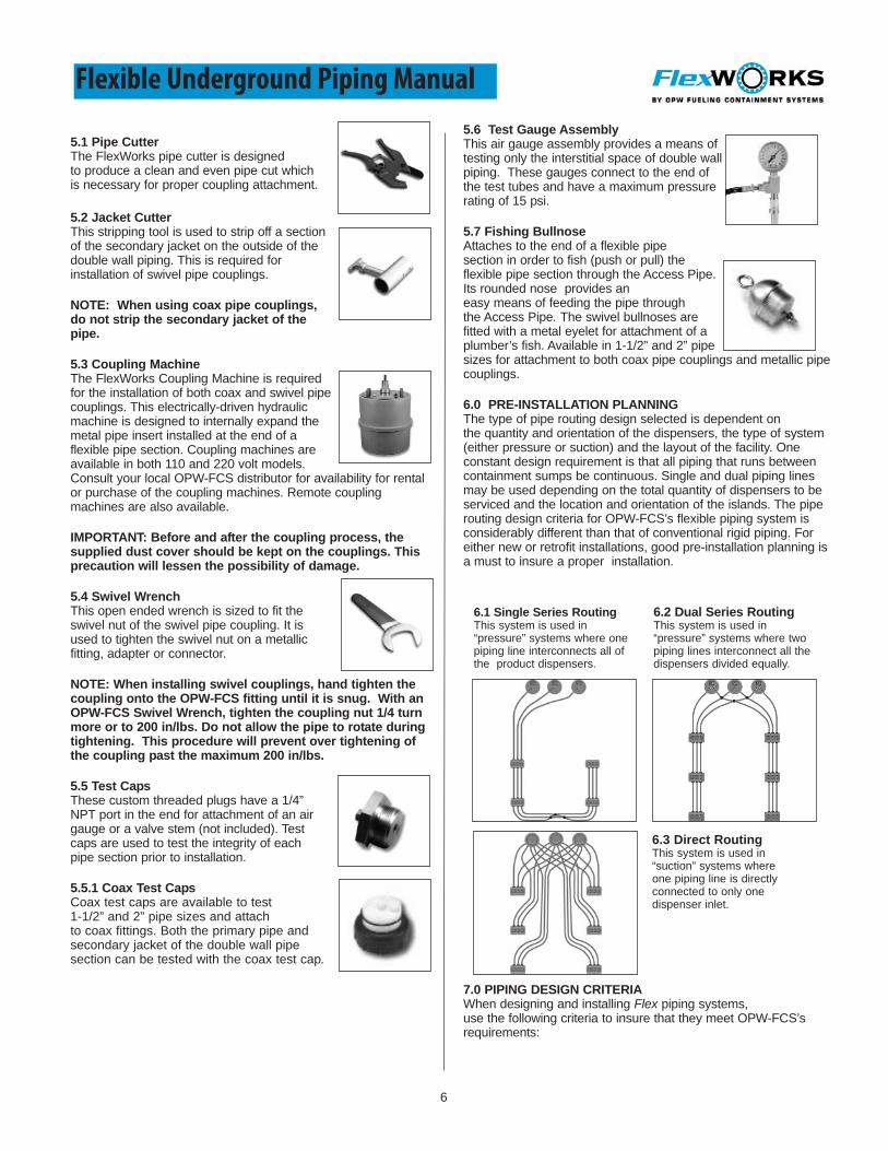
5.1 Pipe Cutter The FlexWorks pipe cutter is designedto produce a clean and even pipe cut whichis necessary for proper coupling attachment.
5.2 Jacket Cutter This stripping tool is used to strip off a sectionof the secondary jacket on the outside of thedouble wall piping. This is required forinstallation of swivel pipe couplings.
NOTE: When using coax pipe couplings,do not strip the secondary jacket of thepipe.
5.3 Coupling Machine The FlexWorks Coupling Machine is requiredfor the installation of both coax and swivel pipecouplings. This electrically-driven hydraulicmachine is designed to internally expand themetal pipe insert installed at the end of aflexible pipe section. Coupling machines areavailable in both 110 and 220 volt models.Consult your local OPW-FCS distributor for availability for rentalor purchase of the coupling machines. Remote couplingmachines are also available.
IMPORTANT: Before and after the coupling process, thesupplied dust cover should be kept on the couplings. Thisprecaution will lessen the possibility of damage.
5.4 Swivel WrenchThis open ended wrench is sized to fit theswivel nut of the swivel pipe coupling. It isused to tighten the swivel nut on a metallicfitting, adapter or connector.
NOTE: When installing swivel couplings, hand tighten thecoupling onto the OPW-FCS fitting until it is snug. With anOPW-FCS Swivel Wrench, tighten the coupling nut 1/4 turnmore or to 200 in/lbs. Do not allow the pipe to rotate duringtightening. This procedure will prevent over tightening ofthe coupling past the maximum 200 in/lbs.
5.5 Test CapsThese custom threaded plugs have a 1/4”NPT port in the end for attachment of an airgauge or a valve stem (not included). Testcaps are used to test the integrity of eachpipe section prior to installation.
5.5.1 Coax Test CapsCoax test caps are available to test1-1/2” and 2” pipe sizes and attachto coax fittings. Both the primary pipe andsecondary jacket of the double wall pipesection can be tested with the coax test cap.
5.6 Test Gauge AssemblyThis air gauge assembly provides a means oftesting only the interstitial space of double wallpiping. These gauges connect to the end ofthe test tubes and have a maximum pressurerating of 15 psi.
5.7 Fishing BullnoseAttaches to the end of a flexible pipesection in order to fish (push or pull) theflexible pipe section through the Access Pipe.Its rounded nose provides aneasy means of feeding the pipe throughthe Access Pipe. The swivel bullnoses arefitted with a metal eyelet for attachment of aplumber’s fish. Available in 1-1/2” and 2” pipesizes for attachment to both coax pipe couplings and metallic pipecouplings.
6.0 PRE-INSTALLATION PLANNINGThe type of pipe routing design selected is dependent onthe quantity and orientation of the dispensers, the type of system(either pressure or suction) and the layout of the facility. Oneconstant design requirement is that all piping that runs betweencontainment sumps be continuous. Single and dual piping linesmay be used depending on the total quantity of dispensers to beserviced and the location and orientation of the islands. The piperouting design criteria for OPW-FCS’s flexible piping system isconsiderably different than that of conventional rigid piping. Foreither new or retrofit installations, good pre-installation planning isa must to insure a proper installation.
7.0 PIPING DESIGN CRITERIAWhen designing and installing Flex piping systems,use the following criteria to insure that they meet OPW-FCS’srequirements:
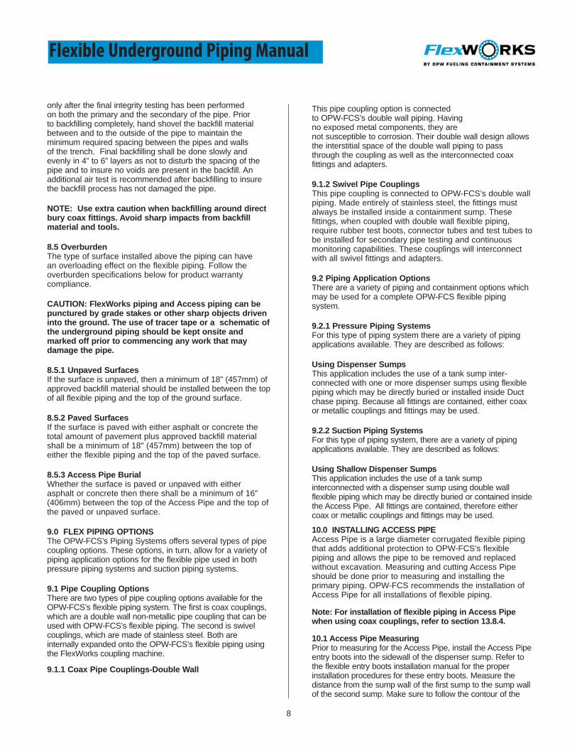
6.3 Direct RoutingThis system is used in“suction” systems whereone piping line is directlyconnected to only onedispenser inlet.
6.1 Single Series RoutingThis system is used in“pressure” systems where onepiping line interconnects all ofthe product dispensers.
6.2 Dual Series RoutingThis system is used in“pressure” systems where twopiping lines interconnect all thedispensers divided equally.

7
Flexible Underground Piping Manual
7.1 Piping TurnsPiping trenches should be cut with sweeping turns. Flexiblepiping turns require specific radii depending on the pipediameter. Piping turns should not be less than:
7.2 Piping CrossoversFor flexible piping systems which have piping crossovers,install the crossover supports at each intersection. 1-1/2”and 2” only.
Note: When crossover supports are not available, aminimum compacted layer of either 2” of approved peagravel or crushed stone or 4” of approved sand backfillmust separate each pipe.
7.3 Piping Supply CapacityFor a pressure piping system using single piping runsrouted in series, no more than a total of six dispensingnozzles should be serviced with a 1-1/2” single piping lineto prevent unacceptable product flow rates. Consult OPW-FCS’s customer service department for flow ratecalculations.
7.4 Vent Piping FallIf Vent Piping is used for vent lines, make sure there isadequate fall back to the tank from the vent stack. OPW-FCS requires a minimum 1/8” per foot slope for all vent lines.
7.5 Product SequenceThe dispensing product sequence will alternate from onedispenser to the next when "loop-around" is used. Pipecrossovers are recommended at these points to correct thechange in product sequence in "series" routing of pressurepiping systems.
8.0 PIPE BURIAL REQUIREMENTSOPW-FCS’s flexible piping and access piping are strong, yetstill flexible, piping systems and must be buried in such amanner that they will not compress.The burial requirementsdepend on proper pipe trenching, backfill materialand burial depth. Follow these instructions for warrantycompliance:
8.1 Trench Sizing Piping trenches should be dug in such amanner that the trench width is equal toat least twice the width of all the flexiblepipes contained within. All piping withinthe trench should be separated by theoutside diameter of the piping beinginstalled with a required minimum of 2”(50 mm) of separation for all piping.Trench turns should be sweeping ratherthan sharp angles. The bottom of the trench should be
.75” - 18” radius1.0” - 18” radius1.5” - 24” radius2” - 36” radius3” - 72” radius
compacted and as uniform as possible to eliminate high spotsto insure an even layer of bedding material under the pipe.Remove all sharp rocks and debris from the trench bottombefore bedding material is installed.
8.2 Bedding & Backfill MaterialsApproved bedding and backfill materials forOPW-FCS’s flexible piping, sumps andAccess piping shall meet the followingspecifications:
8.2.1 Pea GravelRounded pea gravel is permitted with aminimum diameterof 1/8" and a maximum diameter of 3/4".
8.2.2 Crushed StoneCrushed stone is permitted providing it shall be washedclean and be of the free flowing type with an angular stonesize between 1/8" and 1/2". (Meets ASTM C-33 paragraph 9.1requirements.)
8.2.3 SandSand backfill is permitted providing it shall be washed cleanand is free flowing with a maximum content of 10% fines.When backfilling, make sure sand is evenly distributed andfully compacted under and fully around the piping.
NOTE: A minimum of 6” (152mm) of approved beddingmaterial shall be spread and compacted evenly alongthe bottom of the piping trench. All bedding and backfillmaterial should be clean and free from ice and snow anddebris. Using material other than those described abovewithout written approval from OPW-FCS Products Inc.will void the product warranty.
8.3 Flexible Pipe SlopingIf a continuous slope or "fall" is required from the lastdispenser on a piping run to the tank, then the tanks shouldbe buried at a sufficient depth and the pipe entry height intothe dispenser sump should be of sufficient elevation so that1/8" of fall per linear foot is maintained. OPW-FCS does notrequire its flexible pipe to be sloped in pressure systems.
8.3.1 Pressure Piping Systems If the full system warranty is desired, the difference inelevation of the piping between two dispenser sumps mustnot be greater than 30”. A pipe sensor must also be placed inthe terminating dispenser sump or tank sump, whichever is ata lower elevation.
NOTE: Check your local code regulations for fallrequirements other than that which is previously stated.
8.3.2 Suction Piping SystemsSloping the OPW-FCS flexible piping from the dispenser backto the tank is always required for suction piping systemswhere maintaining prime is necessary. Shallow dispensersumps are recommended for use in this application.
8.4 Pipe Trench BackfillingBackfilling of the flexible Piping System should occur
8
Flexible Underground Piping Manual
only after the final integrity testing has been performedon both the primary and the secondary of the pipe. Priorto backfilling completely, hand shovel the backfill materialbetween and to the outside of the pipe to maintain theminimum required spacing between the pipes and wallsof the trench. Final backfilling shall be done slowly andevenly in 4” to 6” layers as not to disturb the spacing of thepipe and to insure no voids are present in the backfill. Anadditional air test is recommended after backfilling to insurethe backfill process has not damaged the pipe.
NOTE: Use extra caution when backfilling around directbury coax fittings. Avoid sharp impacts from backfillmaterial and tools.
8.5 OverburdenThe type of surface installed above the piping can havean overloading effect on the flexible piping. Follow theoverburden specifications below for product warrantycompliance.
CAUTION: FlexWorks piping and Access piping can bepunctured by grade stakes or other sharp objects driveninto the ground. The use of tracer tape or a schematic ofthe underground piping should be kept onsite andmarked off prior to commencing any work that maydamage the pipe.
8.5.1 Unpaved SurfacesIf the surface is unpaved, then a minimum of 18" (457mm) ofapproved backfill material should be installed between the topof all flexible piping and the top of the ground surface.
8.5.2 Paved SurfacesIf the surface is paved with either asphalt or concrete thetotal amount of pavement plus approved backfill materialshall be a minimum of 18" (457mm) between the top ofeither the flexible piping and the top of the paved surface.
8.5.3 Access Pipe BurialWhether the surface is paved or unpaved with eitherasphalt or concrete then there shall be a minimum of 16"(406mm) between the top of the Access Pipe and the top ofthe paved or unpaved surface.
9.0 FLEX PIPING OPTIONSThe OPW-FCS’s Piping Systems offers several types of pipecoupling options. These options, in turn, allow for a variety ofpiping application options for the flexible pipe used in bothpressure piping systems and suction piping systems.
9.1 Pipe Coupling OptionsThere are two types of pipe coupling options available for theOPW-FCS’s flexible piping system. The first is coax couplings,which are a double wall non-metallic pipe coupling that can beused with OPW-FCS’s flexible piping. The second is swivelcouplings, which are made of stainless steel. Both areinternally expanded onto the OPW-FCS’s flexible piping usingthe FlexWorks coupling machine.
9.1.1 Coax Pipe Couplings-Double Wall
This pipe coupling option is connectedto OPW-FCS’s double wall piping. Havingno exposed metal components, they arenot susceptible to corrosion. Their double wall design allowsthe interstitial space of the double wall piping to passthrough the coupling as well as the interconnected coaxfittings and adapters.
9.1.2 Swivel Pipe Couplings This pipe coupling is connected to OPW-FCS’s double wallpiping. Made entirely of stainless steel, the fittings mustalways be installed inside a containment sump. Thesefittings, when coupled with double wall flexible piping,require rubber test boots, connector tubes and test tubes tobe installed for secondary pipe testing and continuousmonitoring capabilities. These couplings will interconnectwith all swivel fittings and adapters.
9.2 Piping Application OptionsThere are a variety of piping and containment options whichmay be used for a complete OPW-FCS flexible pipingsystem.
9.2.1 Pressure Piping SystemsFor this type of piping system there are a variety of pipingapplications available. They are described as follows:
Using Dispenser SumpsThis application includes the use of a tank sump inter-connected with one or more dispenser sumps using flexiblepiping which may be directly buried or installed inside Ductchase piping. Because all fittings are contained, either coaxor metallic couplings and fittings may be used.
9.2.2 Suction Piping SystemsFor this type of piping system, there are a variety of pipingapplications available. They are described as follows:
Using Shallow Dispenser SumpsThis application includes the use of a tank sumpinterconnected with a dispenser sump using double wallflexible piping which may be directly buried or contained insidethe Access Pipe. All fittings are contained, therefore eithercoax or metallic couplings and fittings may be used.
10.0 INSTALLING ACCESS PIPEAccess Pipe is a large diameter corrugated flexible pipingthat adds additional protection to OPW-FCS’s flexiblepiping and allows the pipe to be removed and replacedwithout excavation. Measuring and cutting Access Pipeshould be done prior to measuring and installing theprimary piping. OPW-FCS recommends the installation ofAccess Pipe for all installations of flexible piping.
Note: For installation of flexible piping in Access Pipewhen using coax couplings, refer to section 13.8.4.
10.1 Access Pipe MeasuringPrior to measuring for the Access Pipe, install the Access Pipeentry boots into the sidewall of the dispenser sump. Refer tothe flexible entry boots installation manual for the properinstallation procedures for these entry boots. Measure thedistance from the sump wall of the first sump to the sump wallof the second sump. Make sure to follow the contour of the

9
Flexible Underground Piping Manual
trench. Add 4.25” to this figure and transfer measurement tothe Access Pipe.
10.2 Access Pipe CuttingTransfer measurement to theAccess Pipe and make cut in theclosest valley.
10.3 Access Pipe ConnectionsInsert the black stiffener into theAccess Pipe, then insert the AccessPipe into the flexible boot fromoutside of the sump. Be sure theedge of the Access Pipe is flush withthe inside face of the boot. After theAccess Pipe has been positioned,install the band clamps around theboot. Repeat this same installationprocedure with the other endof the Access Pipe section.
11.0 TANK SUMP PLUMBING TREESThe type of piping application used shall determine what typeof piping connections shall be made inside the tank sump.
NOTE: Prior to assembling plumbing trees, be sure theOPW-FCS fittings are aligned with the pipe entriesthrough the sump wall to prevent excessive bending ofthe pipe within the sump.
11.1 Pressure Supply SystemsFor pressure piping systems, the flexible piping may beconnected to the tank’s submersible pump using the Flexfittings or a flexible connector. For this application, bothsingle and dual line connections may be made.
11.1.1 Single Pipe Line To Pump ConnectionsThis application includes a plumbing treeassembly which interconnects thesubmersible pump to a single flexible pipingline. A typical pipe connection assemblywould include a ball shut-off valve andstandard plumbing elbow installed betweenthe submersible pump and the pipe adapter,as shown.
For coax type connections, a plumbing assembly fitted witha standard plumbing elbow fitting would be connected to acoax
pipe adapter. This accommodates theconnection of a coax pipe couplinginstalled on the end of a flexible pipesection. The adapter is attached by firstapplying the specified thread sealant to themale pipe threads. Then hand tightenfirmly followed by two full turns with a pipewrench.
CAUTION: Do not apply the plumbing wrench to thesection of the pipe adapter which contains the test port.
NOTE: For coaxial fitting NPT threads, use only ULclassified thread sealant specifically formulated forgasoline and petroleum products. Do not overtighten coaxtype fittings.
For swivel type piping connections, aplumbing assembly fitted with a standardplumbing elbow fitting would be connectedto a swivel or barbed adapter.The arrangement accommodates theconnection of a swivel pipe couplinginstalled on the end of a flexible pipesection.
11.1.2 Dual Pipe Lines To Pump ConnectionsThis application includes a plumbing tree assembly whichinterconnects the submersible pump to two flexible pipinglines. A typical connection assembly would include a tee fittingor a dual adapter fitting fitted with a ball shut-off valve and twostandard plumbing elbows as shown.
For coax type connections, a plumbing assembly fitted withtwo standard plumbing elbow fittings would be connected totwo coax pipe adapters. This arrangement accommodates theconnection of coax pipe couplings which are installed on theend of two flexible pipe sections. The adapter is attached byfirst applying the specified thread sealant to the male pipethreads. Then hand tighten firmly followed by two full turns witha pipe wrench.
CAUTION: Do not apply the plumbing wrench to thesection of the pipe adapter which contains the test port.
NOTE: For coaxial fitting NPT threads, use only ULclassified thread sealant specifically formulated forgasoline and petroleum products. Do not overtighten coaxtype fittings.
For swivel type piping connections, a plumbing assembly fittedwith two standard plumbing elbow fittings would be connectedto swivel or barbed adapter. This arrangement is toaccommodate the connection of swivel pipe couplings installedon the end of two flexible pipe.
11.2 Suction Supply SystemsFor suction systems, all flexible piping connections are madedirectly into the tank. In this application typically a tankmanway cover would be fitted with a multitude of femalethreaded tank fittings. These tank fittings should have pipefittings, either a standard plumbing elbows or capped tees

10
Flexible Underground Piping Manual
installed and aligned facing the entry point of the flexible pipesections.
11.2.1 Coax Connections To Tank FittingsInstall the coax pipe adapters into the pipe fittings toaccommodate the coax pipe couplings installedto the end of the flexible pipe sections. The adapters areattached by first applying thread sealant to the male pipethreads. Then hand tighten firmly followed by two full turnswith a pipe wrench.
CAUTION: Do not apply the plumbing wrench to thesection of the pipe adapter which contains the test port.
NOTE: For coaxial fitting NPT threads, use only UL®
classified thread sealant specifically formulated forgasoline and petroleum products. Do not overtightencoax type fittings.
11.2.2 Metallic Connections To Tank FittingsInstall the metallic pipe adapters into the pipe fittings toaccommodate the metallic pipe couplings installed to theend of the flexible pipe sections.
12.0 DISPENSER SUMP PIPE CONNECTIONSThe plumbing connectionsrequired inside dispenser sumpscan be simple or complicateddepending upon the plumbingrequirements, dispenser size, andpipe entry locations. Pipe entriesthat are located considerably offthe center line may require the useof flex connectors as riser pipesinstead of rigid steel riser pipes.For some dispenser models, thepipe entries are located so close to the wall of the dispenserthat product offsets are required. The type of pipingapplication specified shall determine what type of pipingconnections shall be made inside dispenser sumps.
NOTE: Prior to all flexible piping connections indispenser sumps the riser pipe assemblies must beinstalled and test boots, if used, must be installed.
12.1 Riser Pipe AssembliesRiser pipe assemblies are designed to interconnect oneor two flexible pipe sections to the above ground productdispenser. At the top end they may or may not be fittedwith a shear valve and are typically mounted to a stabilizerbar. At the low end they may be fitted with either tee fittingsor elbow fittings. Refer to the following riser pipe optionsavailable with OPW-FCS’s flexible piping system.
12.1.1 Steel Pipe Riser Measuring:Cutting the steel riser pipe to the proper length willallow the piping to enter the dispenser sump on a straightand level plane and in line with the tees, elbows andadapters. Improper riser length results in stress at the pipefitting/pipe coupling connection. Please follow the stepsnoted below:
• Install the stabilizer bars in their proper position, per OPW FCS Stabilizer Bar Installation Instructions, which
can be determined by the dispenser manufacturer’s footprint for the particular dispenser model. This will allowfor proper vertical alignment.
• Install the shear valve to the shear valve mounting plate and secure this to the stabilizer bar in accordance with the dispenser manufacturer’s footprint.
• Install the entry boots in accordance with the OPW-FCS Flexible Entry Boot installation instructions.
• Line up the center of the entry boot with the center of the opening of the tee, elbow or adapter.
• Determine the length of the steel riser by measuring between the bottom of the shear valve and the top of the tee, then add 1-1/2” to that length prior to cutting the NPTthreads for each end of the riser.
• Install the riser to the top of the shear valve with the use of soft set pipe dope that is approved for use with petroleum products.
• Install the tee, elbow or adapter to the bottom of the riser,positioning it properly to align with the entry boot horizontally, with the use of soft set pipe dope that is approved for use with petroleum products.
• Reinstall the riser set up to the stabilizer bar and then make sure that the tee, elbow or adapter opening is on center with the entry boot opening on both the horizontal and vertical plane.
• Assure that the opening of the tees, elbows or adapters are all on center with the entry boot, on both the horizontal and vertical plane.
12.2 Non-Contained Riser Pipe Non-contained riser pipe assemblies are only permitted ifthey are to be installed inside dispenser sumps. These riserpipes assemblies may have a coax or swivel fitting installedat the base of the steel riser pipe.
13.0 FLEXIBLE PIPE FABRICATIONAfter all plumbing trees have been installed inside the tanksumps and riser assemblies installed into either the deep orshallow dispenser sumps, fabrication and installation of theflexible piping may proceed.
IMPORTANT: Only currently certified contractors witha valid factory training card are authorized to install Flexpiping.
13.1 Pipe Handling At JobsiteCare must always be taken when handling OPW-FCS’sflexible piping to prevent damage. It is recommended thatthe carton be placed in the sunlight several hours beforemeasuring and cutting the pipe, so the pipe may relax foreasier extension when measuring.
WARNING: Do not drag, cut or scrape the pipe duringinstallation to avoid damage to the external surface ofthe piping. Use only OPW-FCS approved backfill

11
Flexible Underground Piping Manual
materials.
13.2 Cold Weather Pipe HandlingOPW-FCS’s flexible piping can beinstalled in ambient temperaturesas low as zero degrees, providedthat the flexible piping has beensufficiently warmed prior tounrolling. If the pipe is unrolledand straightened while it is warm,it will cool in a straighter positionmaking it easier to install. For coldweather installations where theambient temperature is below 40°F (5° C), it is recommended that the piping cartons be placedin a warm room for 8 hours directly prior to installation. If thisis not possible, then a small hole should be cut in the topcenter of the lid of the carton for insertion of the nozzle of aconventional hair dryer. For piping reels, place a tarp over thereel and then insert the hair dryer nozzle directly into the endof the piping. If this pipe warming procedure is used, do notuse the first 12” of the pipe due to possible damage by thehair dryer. Depending on the ambient temperature, it maytake up to an hour to warm the roll of piping sufficiently.
13.3 Flexible Pipe MeasuringWhen measuring the distance between containmentsumps or pans to determine the proper length of a flexiblepipe section to be installed, it is important to considerthat the pipe is flexible and will not be installed perfectlystraight. A slight weaving of the pipe in the piping trench isrecommended to compensate for expansion and contraction.The recommended measuring and cutting procedures for theflexible piping are described below:
13.3.1 Direct Pipe Burial ApplicationsWhen measuring for direct burial of flexible piping, themeasuring points will be from the face of one adapter/fitting to the next. If swivel couplings and fittings are used,subtract 1” to allow for the length of the two pipe couplingsand cut the piping to that length. For coax application, nomodification to the measurement is necessary.
13.3.2 Access Pipe Burial ApplicationsFor Applications using Access Pipe, measurementsmust be taken through the Access Pipe to insure properlength. Feed the measuring tape through the Access Pipeand measure the distance from the face of the one adapter/fitting to the next. If swivel couplings and fittings are used,subtract 1” to allow for the length of the two pipe couplingsand cut the piping to that length. For coax application, nomodification to the measurement is necessary. See AccessPipe installation instructions for complete information andinstallation steps.
13.4 Flex Pipe CuttingWhen cutting the piping into pipe sections, cut the pipeat the measured cut mark using the pipe cutter tool. Thiscutting tool is designed to make clean and even cuts in thepiping. Clean and even piping cuts are necessary for theproper installation of the OPW-FCS pipe couplings.
13.4.1 Cutter PositioningMark the pipe where it is to be cut.Next position the blade of the pipecutter over the mark.
13.4.2 Blade ActivationSqueeze the handles up and down toactivate the movement of the blade.Continue until the blade will no longercontinue to activate. This procedurewill cause the pipe to slightlycompress.
13.4.3 Pipe CuttingRotate the entire pipe cutter1/4 turn to permit the blade topenetrate the wall of the pipe.Continue to squeeze the handles upand down to complete the entire pipecut. Inspect the cut to make sure it iseven.
NOTE: Do not rotate blade more than 1/4” turn. Inspectedge of cut and inside of piping after cutting for anysigns of damage.
13.5 Stripping Containment JacketIn order to install the swivel pipe coupling to the end of adouble wall pipe section, it is necessary to strip off smallsections of the outer stand-off containment jacket. Theremoval of this section of stand-off jacket permits theinstallation of the coupling or clamp which fits on the outsidesurface of the primary pipe section.
13.5.1 Strip Length SettingThere are two sets of holes on the body of the jacket cutterfor the installation of a “stop pin” used to set the length of thejacket to be cut off.
NOTE: The secondary jacket is not removed whenusing coax couplings.
13.5.2 Pre-strippingRaise and turn the handle to 45 degrees so theblade will be above the surface of the pipe.
13.5.3 Circular CuttingInsert the end of the pipe section completelyinto the jacket cutter. Make sure the pipebottoms against the stop pin. Next lowerthe handle so that it is perpendicular tothe body of the jacket cutter. Rotate thecutter around the pipe two or three timesto make a complete radial cut on thesecondary jacket.
Note: Pipe must bottom out against stop pin to insureproper length of jacket is removed.

12
Flexible Underground Piping Manual
13.5.4 Linear CuttingRaise and turn the handle 90degrees so the handle will beparallel with the jacket cutterbody. Pull the jacket cutter off theend of the pipe to make the linearcut on the secondary jacket.
13.5.5 Jacket RemovalLook closely for the linear cutdown the pipe, and peel thesecondary jacket away at thatpoint from the primary inner pipe.
NOTE: To avoid damage to thepipe, do not use tools otherthan an OPW-FCS jacket cutterto strip the secondary jacket.Inspect outer surface of primary pipe after jacketremoval. For complete instructions, please refer to thejacket cutter installation instructions.
13.6 Coupling Flexible Pipe SectionsThe flexible piping system requires the use of the FlexCoupling Machine for proper installation of the pipe couplingsonto the flexible piping sections. Both coax couplings &fittings and metallic couplings and fittings may be coupledwith the Flex coupling machine providing the correct faceplates and swage is used.
IMPORTANT: Using the coupling machine with pipingand/or couplings not manufactured by OPW-FCS shallvoid the coupling machine warranty. Before and after thecoupling process the supplied dust cover should bekept on the coupling. This precaution will lessen thepossibility of damage. For complete instructions, pleaserefer to the Flex coupling machine installationinstructions.
13.6.1 Machine Set-up• Remove cover and install under the base.
• Install the correct face plate.
• Install the correct threaded shaft.
• Install the correct size swage kit.
• Open the vent plug.
• Plug in machine with extension cord.
IMPORTANT: Connect the coupling machine to aproperly grounded outlet only. Piping must be heldvertically throughout the coupling process.
WARNING: OPW-FCS’s coupling machine is notintrinsically safe and can not be used in hazardousareas.
13.6.2 Positioning Swivel Pipe CouplingInstall the appropriate size faceplate, unscrew and remove
the tapered swage from the threadedshaft. Lubricate the inside of thecoupling insert with metal assemblypaste or white lithium grease. Insertthe pipe coupling assembly, includingthe ferrule over the threaded shaft andseat it onto the face plate.
Note: Do not place ferrule on thepiping. Ferrule must be inserted over the insert of thecoupling.
13.6.3 Installing The Tapered SwageThread the tapered swage onto thethreaded shaft until it meets the backof the pipe coupling assembly.
NOTE: Do not use silicone basedlubricants. Be sure that the swivelnut of the pipe coupling assemblyis flush against the face plate.
13.6.4 Inserting the PipeInsert the end of a flexible pipe sectioninside the pipe coupling until it bottomsout. Inspect the entire assembly, prior toswitching on the machine for thefollowing:
• Swivel nuts are flush against thebase plate.
• The coupling and pipe are totallyvertical.
• The ferrule is snug against the insert shoulder.
13.6.5 SwagingTo begin the swaging process, turn theswitch to the DOWN position. Once thetapered swage passes through the pipecoupling assembly, the motor will turnoff. Remove the coupled pipe section.Turn the switch to the UP position toallow the drive shaft to return to thestarting position.13.6.6 InspectionInspect the installed pipe couplingassembly inside and out to make surethere was no damage to the insert,ferrule or swivel nut during the swagingoperation.
IMPORTANT: Using thiscoupling machine with pipeor couplings other than those manufactured by OPWFueling Containment Systems, shall void the productwarranty.Note: Some flexible entry boots require at least partialinstallation onto the pipe before coupling. When usingswivel couplings in direct bury applications, the studdedportion of a DEB-6150 and DEB-6200 must be installedonto the pipe prior to coupling the pipe. All direct burycoax couplings require the entry boot or reducer donutto be installed prior to coupling the pipe.

13
Flexible Underground Piping Manual
13.6.7 Positioning Coax PipeCouplingInstall the appropriate size faceplate,unscrew and remove the tapered swagefrom the threaded shaft. Lubricate theinside of the coupling insert with metalassembly paste or white lithium grease.Insert the pipe coupling assembly overthe threaded shaft and push it downonto the face plate.
13.6.8 Installing The Tapered SwageThread the tapered swage onto thethreaded shaft until it meets the backof the pipe coupling assembly.
NOTE: Do not use silicone basedlubricants. Be sure that the swivelnut of the pipe coupling assembly isflush against the face plate.
13.6.9 Inserting the PipeInsert the end of a flexible pipe section inside the pipe couplinguntil it bottoms out. Inspect the entire assembly, prior to
a. Notice ferrule not pushed to insert shoulder.b. Piping not pushed over barbs completely.
IMPROPERLY INSTALLED SWIVEL COUPLING
a
PrimaryEnd ofPrimary Pipeb
SecondaryJacket
PROPERLY INSTALLED SWIVEL COUPLING
a. Ferrule properly seated to insert shoulder.b. Primary pipe pushed to the front of the ferrule inside over all
barbs at insert.
a
b Pipe seatedin ferrule Primary
SecondaryJacket
switching on the machine. Make surethe pipe is completely vertical.
• Finish the coupling process as described in 13.6.5 and 13.6.6
IMPORTANT: For direct burial(non-Access Pipe) coaxapplications, loosely pre-installentry boot on pipe, studs facingdownward, prior to inserting pipe on coupling. Replaceorange dust cap after couplings.
13.7 Installing Pipe Sections - Direct Burial (non-AccessPipe) Once the pipe has been measured and the couplings havebeen installed, the pipe may be installed. This sectiondiscusses the installation in a direct burial application. Refer tosection 13.8 for installation of the piping using Access Pipe.
13.7.1 Insert Piping Through Sump WallTake the pipe section to the trench andinsert into the containment sump throughthe flexible entry boot. Make sure theband clamp of the entry boot has beenremoved or sufficiently loosened to permitthe pipe to pass through the rubber boot.Tighten band clamps of the entry bootsafter the installation process has been completed. For junctionsump applications, repeat procedure for adjoining pipesections.
IMPORTANT: For direct burial (non-Access Pipe) coaxapplications, be sure to insert coupled pipe throughopening in the side of the sump. Align studs of theflexible entry boot with stud holes in sump and push intoplace. Fasten the entry boot according to the installationinstructions included with the boot.
13.7.2 Pipe ConnectionAfter the flexible pipe(s) have been inserted, attach pipe tofittings using the methods described in section 14. Inspectthe piping in the trench to make sure it is positioned properlyin the trench between the containment sumps and there issufficient pipe weaving back and forth to allow for pipeexpansion and contraction.
13.8 Installing Pipe Sections-Access PipeOnce the pipe has been properly measured, the couplingshave been installed and dust covers placed back on thecouplings, the pipe is ready to be installed into the duct. Referto section 10 and Access Pipe installation instructions fordetails involving the proper installation of the duct conduit.
13.8.1 Fishing Pipe Through Access PipeRemove Access Pipe conduitfrom entry boots. Attach theappropriate OPW-FCSbullnose to one coupling. Fishrope through the Access Pipeconduit and attach to bullnose.Pull or push flexible pipingthrough Access Pipe conduit.
Note: For installation tipsand techniques see Access

14
Flexible Underground Piping Manual
Pipe installation instructions.
13.8.2 Insert Pipe into SumpAlign the Access Pipe conduit/ flexible piping with the AccessPipe entry boot. Push piping through entry boot and attachcoupling to the fitting using the methods described in section14.
13.8.3 Insert Access Pipe into BootAlign the Access Pipe with entry boot and push into placeuntil duct bottoms out. Tighten band clamps to 30 in. Lbs.
13.8.4 Installation of Duct with Coax Fittings
Step 1. Drill entry boot holes using the appropriate sizehole saw.
Step 2. Measure and cut the lengthof Duct to be installed. Sump wall tosump wall plus four inches (4”). Itis recommended to snake the pipefrom side to side within the trenchto compensate for expansion andcontraction characteristics of the pipe.
Step 3. Insert the outside portion ofthe Duct boot into the sump wall. Loosely install the Ductinto the boot and measure from the face toface of the pre-installed Coax tee or elbow fittings withineach sump. Cut the Flex flexible piping to thismeasurement with an OPW-FCS pipe cutter. DO NOTCOUPLE THE PIPE.
Step 4. Using a Barbed Bull Nose fitting (FBN-3150 orFBN-3200), insert the Flex piping through the section ofDuct. It is recommended to start with the longest runs so ifa mistake is made, the section can be used on a shortersection of the site.
Step 5. In the following order, prepare the pipe to becoupled.
1. Place the outside portion of the Access Pipe boot overthe Duct, studs pointing towards the end of the pipe.
2. Slip the black boot stiffener over the Flex and into theend of th e Access pipe.
3. Slide the inside “nose” portion of the Access Pipe bootonto the end of the Flex pipe. Be sure the smaller openingof the boot is towards the pipe end.
Step 6. Coupling the Pipe. With the pipe still inside theAccess Pipe, raise the entire assembly over the OPW-FCScoupling machine with a Coax coupling in position on themachine. Be sure the Flex pipe is vertical at the end andenters the Coax Coupling squarely then couple the pipe.
Repeat steps 5 and 6 on the other end of the pipe section.
Step 7. Insert the pipe assembly and boot nose throughthe pre-drilled hole in sump. The nose of the boot is flexibleand can be folded. Use soapy water if needed.
Step 8. Prior to installing the Coax coupling to the fitting,place the compression ring of the boot over the couplingend of the pipe and complete the installation of the AccessPipe entry boot. Tighten all compression rings in aclockwise pattern not exceeding 60 in/lbs. If sealant is usedon the outside portion of the entry boot, it should beapplied during this step.
Step 9. Fully insert the Access Pipe and black stiffenerinto the Access Pipe Entry Boot and install all band clamps.Do not exceed 30 in/lbs on band clamp assemblies.
Step 10. Repeat steps 7 through 9 on the other end of thepipe. You may need to compress the Access Pipe in anaccordion fashion when installing the Access Pipe at theend of the procedure. Air test Access Pipe if desired.
14.0 PIPING CONNECTIONSAfter all containment sumps have been interconnected withall of the flexible pipe sections, all riser pipe assemblies andtest boots (if required) have been installed, then all pipingconnections may proceed. There is a different installationprocedure for each type of piping connection. Comply withthe following connection procedures for each type.
14.1 Coaxial Coupling ConnectionsCoax couplings do not require the use of any tools fortightening. The following connection procedure needsto be followed for proper installation:
14.1.1 Coupling InspectionPrior to connection, inspectcoupling to make sure all rubberO-rings are properly in place andseated inside the O-ring grooves.Look for any dirt or damage to theO-rings which may have occurredduring the coupling procedure.Coax nut must be fully seated forproper connection.
14.1.2 Fitting InspectionRemove the plastic protective cap from the fitting or adapter.Inspect the fitting or adapter to be sure that it is free of sandor debris in the core area and on the threads.
14.1.3 Tightening Coax NutPush the pipe coupling onto thecore of the fitting or adapter andhand tighten the coax swivel nutonto the threads of the fitting. Besure that the piping does nottwist while hand tightening, andverify that upon tightening, nothreads are visible.
NOTE: Tighten by hand only until coupling bottoms outinto fitting. Do not continue to tighten the nut once thecoupling has stopped.
15
Flexible Underground Piping Manual
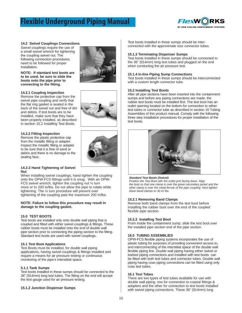
14.2 Swivel Couplings ConnectionsSwivel couplings require the use ofa small swivel wrench for tighteningthe coupling swivel nut. Thefollowing connection proceduresneed to be followed for properinstallation.NOTE: If standard test boots areto be used, be sure to slide theboots onto the pipe prior toconnecting to the fitting.
14.2.1 Coupling InspectionRemove the protective cap from theswivel pipe coupling and verify thatthe flat ring gasket is seated in theback of the swivel nut and free of dirtand debris. If test boots are to beinstalled, make sure that they havebeen properly installed, as describedin section 15.2 Installing Test Boots.
14.2.2 Fitting InspectionRemove the plastic protective capfrom the metallic fitting or adapter.Inspect the metallic fitting or adapterto be sure that it is free of sand ordebris and there is no damage to thesealing face.
14.2.3 Hand Tightening of SwivelNutWhen installing swivel couplings, hand tighten the couplingonto the OPW-FCS fittings until it is snug. With an OPW-FCS swivel wrench, tighten the coupling nut ¼ turnmore or to 200 in/lbs. Do not allow the pipe to rotate whiletightening. The ¼ turn procedure will prevent overtightening of the coupling past the maximum 200 in/lbs.
NOTE: Failure to follow this procedure may result indamage to the coupling gasket.
15.0 TEST BOOTSTest boots are installed only onto double wall piping that iscoupled and fitted with either swivel couplings & fittings. Theserubber boots must be installed onto the end of double wallpipe section prior to connecting the piping section to the fitting.Standard test boots are used with swivel couplings.
15.1 Test Boot ApplicationsTest Boots must be installed, for double wall pipingapplications, having swivel couplings & fittings installed andrequire a means for air pressure testing or continuousmonitoring of the pipe’s interstitial space.
5.1.1 Tank SumpsTest boots installed in these sumps should be connected to the36" (914mm) long test tubes. The fitting on the end will acceptthe test gauge used for air pressure testing.
15.1.2 Junction Dispenser Sumps
Test boots installed in these sumps should be inter-connected with the approximate size connector tubes.
15.1.3 Terminating Dispenser SumpsTest boots installed in these sumps should be connected tothe 36" (914mm) long test tubes and plugged on the endwhen conducting the air pressure test.
15.1.4 In-line Piping Sump ConnectionsTest boots installed in these sumps should be interconnectedwith a custom length connector tube.
15.2 Installing Test BootsAfter all pipe sections have been inserted into the containmentsumps and before any piping connections are made, therubber test boots must be installed first. The test boot has anoutlet opening located on the bottom for connection to eithertest tubes or connector tube as described in section 16 TubingAssemblies of this product manual. Comply with the followingthree step installation procedures for proper installation of thetest boots.
15.2.1 Removing Band ClampsRemove both band clamps from the test boot beforeinstalling the rubber boot over the end of the coupledflexible pipe section.
15.2.2 Installing Test BootFrom inside the containment sump, slide the test boot overthe installed pipe section end of the pipe section.
16.0 TUBING ASSEMBLIESOPW-FCS flexible piping systems incorporates the use ofplastic tubing for purposes of providing convenient access to,and interconnecting of the interstitial space of the double wallflexible piping line. Double wall piping having either swivel orbarbed piping connections and installed with test boots canbe fitted with both test tubes and connector tubes. Double wallpiping having coax piping connections can be fitted using onlycoax test tubes.
16.1 Test TubesThere are two types of test tubes available for use withdouble wall piping: one for connection to coaxial fittings &adapters and the other for connection to test boots installedwith swivel piping connections. These 36” (914mm) long
Standard Test Boots (Swivel)Position the Test Boot with the outlet port facing down. Alignthe boot so that one clamp is over the green secondary jacket and theother clamp is over the metal ferrule of the pipe coupling. Next tightendown band clamps to 30 in/ lbs.

16
Flexible Underground Piping Manual
plastic tubes assemblies are designed to provide convenientaccess to the beginning and end of a double wall pipe line forinitial and periodic air pressure integrity testing.
16.1.1 Coax Test TubesThese 3/8” tubes are 36” long(914mm) with a 1/4” female fittinginstalled on one end. The other endhas a nylon male 1/4” NPT threadedconnection which connects to the 1/4”NPT threaded test port of the coaxpipe adapter.
CAUTION: Do not install metallicfittings into Coax test ports.
16.1.2 Standard Test TubesThese 3/8” tubes are 36” long (914mm) with a 1/4” femalebrass fitting installed on one end. The other end has a malebarbed elbow with band clamp attached for connection to the3/8” port of the rubber test boot used with metallic couplings &fittings.
16.2 Connector TubesThese short plastic tube assemblies connect one test bootto another to reroute the interstitial space of one flexible pipesection around a tee or connector fitting to the next flexible pipesection.
16.2.1 Connected Connector TubesAfter initial integrity testing has been completed, the connectortubes can remain connected if interstitial product flow is desiredto run the length of the pipe line back to the tank sump.
NOTE: Dispenser sump leak detection is required tomonitor the integrity of piping, when the connector tubesare connected.
16.2.2 Disconnected Connector TubesAfter initial integrity testing has been completed, the connectortubes can be disconnected if interstitial product flow is desiredfrom sump to sump. One end in each dispenser sump shouldbe disconnected from the test boot.
17.0 VENT FLEXIBLE VENT PIPINGThis flexible piping is used for the transmission of aromaticfuel vapors and is designed for direct burial of the pipe andfittings without the requirement for secondary containment.The intended use for Vent is for venting vapors from anunderground storage tank to a remotely located vent stack.
IMPORTANT: Vent is available in both 2” and 3” sizes andis not intended for the transfer of fluids.
17.1 Vent ConnectionsThe Vent piping system requires the use of swivel couplings &fittings. Unlike supply piping connections OPW-FCS permits Ventswivel connections to be direct buried when properly protected.
17.2 Tank Connections Within Tank SumpIf the tank’s vent connection is con-tained within a tank sump, thevent line should enter through a flexible entry boot. A male orfemale adapter fitting should be used to complete the connectionwithin.
17.3 Tank Connections Extractor FittingIf the tank’s vent connection is not contained within a tanksump, then a male or female adapter fittingshould be installed in the extractor fitting to accept the OPW-FCS Piping. The adapter and coupling/fitting should beproperly protected.
17.4 Pipe Branch ConnectionsIn between the beginning and end of a Vent piping line it maybe necessary to install tee fittings to interconnect numerouspipe runs into a main return line to the tank. For thisapplication the coax junction tee or coax branch tee may beused.
17.5 Vent Stack Connections At the other end of a Vent™ pipe line the pipe connectsto a vent stack for tank vapor venting applications. Thisconnection is made using an elbow fitted to the appropriatecoupling. Metallic fittings may be wrapped with pipe tapeto further protect the fitting components from corrosion.
18.0 TESTING & FILLING SUPPLY PIPEIt is important to properly test the flexible piping prior tobackfill to insure there are no leaks. The following testprocedures are provided as a guideline only and themanufacturer assumes no responsibility or liability for theconsequences of any testing practices.
IMPORTANT: Integrity testing with air or gas can bedangerous and it is very important that the propertesting equipment be used and that the pre-testingprocedures be read.
18.1 Testing Equipment
• Pressurizing equipment should be of sufficient size toaccommodate line pressure testing requirements.
• Pressurizing equipment should have controls to graduallyincrease pressures.
• Pressurizing equipment should be operated byexperienced and qualified personnel only.
• The pressure gauge should be located in close proximity to the pressurizing equipment.
• Pressure gauges must have a full scale reading not toexceed twice the required test pressure.
• Pressure gauges should be accurately and routinelytested for reliability.
18.2 Pre-Testing Procedures• The underground storage tank should be isolated from
the piping system prior to hydrostatic or air testing.• Shear valves located under dispensers
should be sealed with pressure rated plugs or caps.• Long flex piping runs should be secured at various
points with backfill material.• All pipe coupling/swivel connections should be
tightened securely before testing.• The interstitial (secondary) line should be
interconnected and fitted with an air gauge.• All local building, safety and fire codes should be
followed prior to and during testing.
17
Flexible Underground Piping Manual
18.3 Air Pressure Testing ProceduresThe air pressure integrity test procedure for the flexiblesupply piping is one and one half (1-1/2) times the normaloperating pressure of the submersible pump, not to exceedsixty pounds per square inch (60 psi). Make sure the flexiblepipeline is isolated from both the underground storage tankand the above ground product dispenser when conductingthis test. All pressure testing should be conducted byqualified and experienced personnel. Do not attempt todisconnect couplings, caps, or plugs unless the air pressurehas been released.
NOTE: Testing requirements must be in accordancewith all applicable codes.
18.3.1 Air PressurizeGradually apply air pressure into the flexible piping line. Donot exceed sixty pounds per square inch (60 psi) or 416 kPa.
18.3.2 Air Pressure HoldingMaintain pressure for a minimum of three hours, making surethat there is no drop in pressure.
Note: Significant temperature changes can result in apressure reading differential.
18.3.3 Air Pressure Holding for Coax PRE-BACKFILL Maintain pressure for a minimum of threehours. POST-BACKFILL Maintain pressure for a minimumof three hours.
NOTE: Do not close off or apply pressure to secondaryjacket until primary pressure is maintained for aminimum of one hour.
18.3.4 Test Tube Gauge CheckDuring pressurizing, check the reading on the test gaugewhich should be connected to the test tube of the inter-connected interstitial line. Any increase in pressure willindicate a leak.
18.3.5 Soap TestDuring the pressurizing period, apply a soapy water solution toall piping connections and inspect for bubbles.
18.4 Hydrostatic Testing Procedures (if applicable)The recommended hydrostatic pressure integrity testprocedure for the flexible supply piping is one and onehalf (1-1/2) times the normal operating pressure of thesubmersible pump, not to exceed sixty pounds per squareinch (60 psi). Make sure the flexible pipeline is isolatedfrom the underground storage tank and the above groundproduct dispenser when conducting this test. All pressuretesting should be conducted by qualified and experiencedpersonnel. Do not attempt to disconnect couplings, caps, orplugs unless the air pressure has been released.
Note: OPW-FCS recommends hydrostatic testing on allsumps after installation is complete to check for propersealing of joints and connections.
18.4.1 Water FillingGradually introduce water at the lowest point into the pipingsystem and bleed off air at the highest point in the piping
system through an open valve. The hydrostatic pressureapplied should not exceed 60 psi.
18.4.2 Pressure Hold InspectionMaintain pressurization for a minimum of one hourmaking sure there is no drop in pressure. Significanttemperature changes can result in a pressure readingdifferential. During the pressurizing period, inspect allpiping connections for leaks.
18.5 Supply System FillingAfter the supply piping system has been integrity testedand connected to the product dispensers, filling of thepipe line may commence. There should be a controlledmethod for filling the supply line which provides anadequate means of removing air from the lines. Do notstart pumps with empty lines, as it may damage the pipeand its connections. Small amounts of trapped air shoulddissipate under normal operations. Make sure that thepressure rating of the submersible pump does not exceedthat of the maximum operating pressure of the pipe.
19.0 PERIODIC LINE LEAK DETECTIONLocal or federal regulations may require periodic line leakdetection tests be performed on the installed pipingsystem. Testing requirements affect both suction andpressure piping systems. A typical requirement is that thepiping lines must be tested on an annual basis at oneand one half (1-1/2) times the normal operating pressure.The typical test method will require detection of 0.10gallons (.3785 liters) per hour with a 95% probability ofdetection and a 5% probability of a false alarm.
The typical test procedure requires the piping be isolatedfrom the tank and the piping line pressurized to 1-1/2times the normal operating pressure. A test apparatuswhich is connected to the piping line will then measurethe bleedback volume of the piping system. Acceptablebleedback volumes on different types of piping systemswill vary due to their inherent expansion and contractioncharacteristics. Therefore, modifications in the testingprocedures are required for piping systems which havesignificant expansion and contraction characteristics. Thischaracteristic is measured in the average volumeincrease, per linear foot under a standard test pressure.
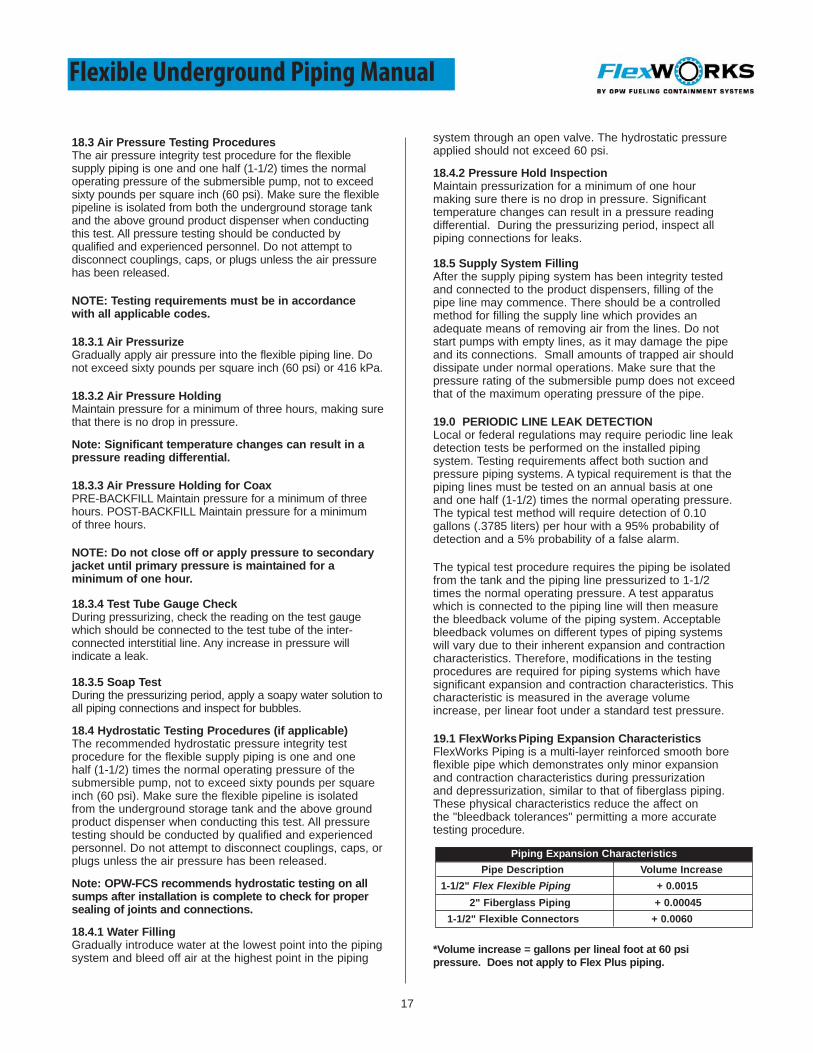
19.1 FlexWorksPiping Expansion CharacteristicsFlexWorks Piping is a multi-layer reinforced smooth boreflexible pipe which demonstrates only minor expansionand contraction characteristics during pressurizationand depressurization, similar to that of fiberglass piping.These physical characteristics reduce the affect onthe "bleedback tolerances" permitting a more accuratetesting procedure.
*Volume increase = gallons per lineal foot at 60 psipressure. Does not apply to Flex Plus piping.
Piping Expansion CharacteristicsPipe Description Volume Increase
1-1/2" Flex Flexible Piping + 0.00152" Fiberglass Piping + 0.00045
1-1/2" Flexible Connectors + 0.0060

18
Flexible Underground Piping Manual
20.0 INTERSTITIAL INTEGRITY TESTINGPrior to supply filling and periodically over the life of theflexible piping system, it is recommended that interstitial testingbe used to ensure that the secondarycontainment is intact.
20.1 Air Pressure/Soap TestingAfter the inner primary flexible pipeand piping connections have beenintegrity tested, the entire interstitialspace of the double wall pipe must remain connected andonly then should the outer containment jacket be integritytested. The connections of the test boots are illustratedand explained in Section 15.2 of this product manual.
20.2 Testing AssemblyInside all tank sumps the test gauge is connected to the endof the test tube. The test gauge assembly consists of an airgauge with a maximum 15 psi scale connected to a 1/4"brass tee fitting with a male 1/4” thread. The gauge threadsdirectly into female brass fitting of the test tubes. The testtube in the terminating sump shall be capped with a .25”brass plug.
20.3 Air Pressure TestingGradually pressurize the piping's interstitial space through thetest tube to no more than 10 psi. During the pressurizationperiod, apply an air pressure soap test to the entire piping line.After testing, disconnect the air hose and lay the test tubedown into the bottom of the tank sump.
IMPORTANT: Coax fittings require interstitial testingbefore and after backfill.
21.0 FLEXWORKS SYSTEM MAINTENANCEThe FlexWorks System is designed to provide reliableunderground fuel transfer and short-term secondarycontainment of leaked petroleum product. FlexWorks sumpsand secondary containment pipes are not intended for longterm storage of petroleum products. Liquid that accumulatesin the secondary containment system must be promptlyremoved and properly disposed of. Operational third partyapproved liquid sensors should be installed and maintainedin each sump to reliably indicate to the operator that liquid ispresent in the secondary containment system. Once a leakis detected, the system must be shut down immediately andthe source of the leak must be repaired. All liquid must bethoroughly flushed and cleaned out of the secondarycontainment system at once. Inspect all system componentsat least monthly for leaks or damage, and repair or replaceany suspect component as necessary.
21.1 ROUTINE SUMP INSPECTIONSVisual inspections of all containment sumps and componentsshould be made on a routine basis to check for damage, waterinfiltration or for any signs of leaking product. An electronic ormechanical shut-off leak detection system is recommended forall containment sumps. When changing fuel filters at thedispenser, make sure any spilled product is cleaned out of thebottom of the dispenser sump. Sumps are to be kept free ofdebris and spilled fuel.
NOTE: Failure to remove fuel and liquids fromcontainment sumps may compromise the performanceand integrity of the sump and its associated fittings and
seals over prolonged periods of time.
Always follow warranty registration instruction andreturn warranty forms to OPW-FCS.
21.2 STORAGE AND TRANSITInstructions shall specify that pipe and fittings are not intendedfor storage in direct sunlight or excessive temperatures andthat rough handling (drops and impacts) during storage andtransit may cause damage and leaking. Any specialprocedures for protection against environmental conditions andphysical abuse during storage and transit shall be identified.Any special procedures for the inspection of parts for non-complying damage before assembly shall be identified withinstructions specifying that a damaged part shall not be used.
22.0 PERIODIC INTERSTITIAL TESTINGFor periodic integrity testing of the interstitial space of thedouble wall pipe there is a different setup procedure forsystems using coax fittings versus steel fittings with connectortubes. Both applications should have test tubes connected oneach end. If they have been disconnected, reconnect thembefore testing. Follow the air pressure test procedures belowfor interstitial integrity testing.
22.1 Reconnect Test TubesIf necessary, reconnect the test tube located inside the tanksump to the test boot. Connect the test gauge assembly tothe top end of the test tube.
22.2 Reconnect Connector TubesIf the piping system includes test boots with connector tubesthen make sure all connector tubes have been reconnected.
22.3 Plug Test TubePlug and seal the test tube fitting located at the terminatingend of the flexible piping line.
22.4 Air PressurizePressurize the interstitial space to 10 psi for a period of onehour, in accordance with Section 21, Interstitial IntegrityTesting. If required, disconnect all tubes after test.
23.0 PROBLEMS
InvestigationIf leakage or damage is detected in any part of thesystem (either by inspection of the sump, a leak detector,or similar monitors), the problems are to be immediatelyinvestigated by the site operator.
Warning: Ignoring or disabling leak detection alarmsmay lead to further damage and possible failure.
NotificationIf leakage or damage to the piping system is verified, notify the Technical Service Department of OPW FuelingContainment Systems at one of the below noted phonenumbers:
• 1-800-422-2525 Toll Free• 1-919-934-2786 Extension 104

19
Flexible Underground Piping Manual
24.0 GUIDE SPECIFICATIONS24.1 Short FormThe contractor shall provide a flexible underground pipingsystem whereby the flexible piping, fittings, adapters andunder dispenser riser pipes are secondarily contained andhaving no metallic components exposed to theenvironment. The primary pipe shall be capable of beingair pressure tested to 1.5 times the operating pressure ofthe pump not exceeding 60 psi. The secondary shall becapable of being air tested to 10 psi.
24.2 Long FormThe following guide specification is designed around theuse of OPW-FCS’s flexible piping.
24.2.1 Design The contractor shall provide a secondarily containedflexible underground piping system that shall providesecondary containment for all primary piping, couplings,fittings and adapters. Piping runs shall be continuousbetween containment chambers (ie., tank & dispensersumps or pans) in which all joints are contained withinthe containment chambers. The piping design shall allowfor any leak in the primary supply or secondarycontainment piping to be directed to a leak detectionsensor.
24.2.2 Product And Chemical CompatibilityThe flexible underground piping and associatedcouplings, fittings and adapters shall be chemicallycompatible with the products to be transported and withchemicals found naturally in the ground environment.The primary & sec-ondary piping shall be compatiblewith gasoline, alcohols, gasoline-alcohol mixtures and allEPA approved additives, including MTBE.
24.2.3 Corrosion ResistanceThe flexible underground piping and associatedcouplings, fittings and adapters which come in contactwith the ground environment shall be made of non-metallicmaterial or encapsulated by non-metallic componentswhich prevent corrosion.
24.2.4 Structural IntegrityThe flexible underground piping and associatedcouplings, fittings and adapters shall be designed andconstructed of materials strong enough for its intendeduse. The flexible piping shall not collapse, crack or breakdue to ground movement or from backfill and highground water pres-sures. Piping shall be able to transferfluid up to a maximum temperature of 125 degreesfahrenheit (52 degrees celsius). Piping shall beoperational with in a temperature band of minus 40Cand +65C.
24.2.5 Bend RadiusThe double wall flexible piping shall be capable of a min-imum bend radius without kinking, cracking or breaking.The minimum bend radii shall be equal to or less thanthe following:
0.75” - 18” radius1.0” - 18” radius
1.5” - 24” radius2.0” - 36” radius3.0” - 48” radius
24.2.6 Fluid Flow EfficiencyBoth the primary inner and secondary outer pipe shall havean interior surface which is a smooth (non-corrugated) profileand be made of a low friction resistant material for improvedfluid flow efficiency.
24.2.7 Operating Pressures & VacuumsThe flexible underground piping shall have a minimum fiveto one (5:1) safety factor from maximum operating pressurefor rated pressure. The maximum operating pressure ratingfor 1.5” diameter piping shall be 100 psi primary and 10 psisecondary. 3/4”, 1”, 2” and 3” piping shall be rated at amaximum operating pressure of 75 psi primary and 10 psisecondary. For suction systems the pipe shall be capableof withstanding 29” mercury vacuum.
24.2.8 Pipe ExpansionThe primary supply pipe shall not expand more than .0025%in diameter and overall length when pressurized to 60 psito permit accurate pressure decay readings by an in-lineleak detector.
24.2.9 Interstitial InterconnectionAll primary and secondary piping shall be connectedin such a way as to permit integrity testing both duringinstallation and at periodic intervals in the future. Bothprimary and secondary piping shall remain continuousduring operation.
24.2.10 UL® Testing Flexible piping and it’s associated fittings shall beindependently tested in accordance with UL 971.
25.0 Storage and Handling
25.1 StorageOPW-FCS requires that all piping, fittings and systemcomponents be stored in such a manner that theywill not be subject to direct sunlight and / or excessiveenvironmental conditions. Please review the belownoted warnings during product storage.
• Cover all products with UV protective tarps if outside.
• If tarps are unavailable, store in trailer or building until use.
25.2 HandlingOPW-FCS requires that the piping, fittings and systemcomponents are handled in such a manner that it will notcause unnecessary damage to the system components.Please review the below noted warnings during producthandling.
• Do not drop, cut or impact the components.
• Keep all piping, fittings and components in the original packaging until ready to use.
• Keep all thread protectors secure until ready to use.
• Keep all coupling protector caps / covers in place.
• DO NOT drag, cut or scrape pipe.
• Upon completion of pipe, inspect for cuts, scrapes and damage prior to close of pipe runs.
• DO NOT exceed 15° angle entry for pipe into a sump.
Please visit our website, www.opwglobal.com, for adetailed guide specification.
20
Flexible Underground Piping Manual

21
Notes

22
LIMITED WARRANTY
NOTICE: FlexWorks by OPW, Inc., VAPORSAVER and all other OPW products must be used in compliance with all applicablefederal, state, provincial and local laws, rules and regulations. Product selection must be based on physical specifications andlimitations, compatibility with the environment and material to be handled. All illustrations and specifications in this literature arebased on the latest production information available at the time of publication. Prices, materials and specifications are subject tochange at any time, and models may be discontinued at any time, in either case, without notice or obligation.
OPW warrants solely to its customer that the following products sold by OPW will be free from defects in materials andworkmanship under normal use and conditions for the periods indicated:
OPW’s exclusive obligation under this limited warranty is, at its option, to repair, replace or issue credit (in an amount not to exceedthe list price for any defective product) for future orders for any product that may prove defective within the applicable warrantyperiod (repairs or replacements are subject to prorated warranty coverage fro remainder of the original warranty period). Completeand proper warranty claim documentation and proof of purchase required. All warranty claims must be made in writing anddelivered during the applicable warranty period to OPW at P.O. Box 405003, Cincinnati, Ohio 45240, Attention: Customer ServiceManager. No products may be returned to OPW without its prior written authority.
This limited warranty shall not apply to any FlexWorks or VAPORSAVER product unless it is installed by an OPW attested installer.This limited warranty also shall not apply to any FlexWorks, VAPORSAVER or other OPW product: unless all required site andwarranty registration forms are completed and received by OPW within 60 days of installation; unless all piping connections areinstalled with a nationally-recognized or state-approved leak detection device in each tank and dispenser sump (which are not forstorage and from which all discharge hydrocarbons must be removed, and the systems completely cleaned, with 24 hours); unlesstestable sumps utilize FlexWorks pipe and access fittings; unless a sump inspection log or an EPA recommended/required checklistis maintained and the results are furnished to OPW upon request; and unless OPW is notified with 24 hours of any known orsuspected product failure and is provided with unrestricted access to the product and the site. This limited warranty also shall notapply to any product which has been altered in any way, which has been repaired by anyone other than a service representativeauthorized by OPW, or when failure or defect is due to: improper installation or maintenance (including, without limitation, failure tofollow FlexWorks Quick Reference Manual Installation Guide and all product warning labels); abuse or misuse; violation of health orsafety requirements; use of another manufacturer’s, or otherwise unauthorized, substances or components; soil or other surface orsubsurface conditions; or fire, flood, storm, lightning, earthquake, accident or any other conditions, events or circumstances beyondOPW’s control.
THIS LIMITED WARRANTY IS IN LIEU OF ALL OTHER WARRANTIES, EXPRESS OR IMPLIED, AND ALL OTHERWARRANTEIS INCLUDING, WITHOUT LIMITATION, THE WARRANTIES OF MERCHANTABILITY AND FITNESS FOR APARTICULAR PURPOSE, ARE HEREBY EXCLUDED. OPW shall have no other liability whatsoever, whether based on breach ofcontract, negligence, gross negligence, strict liability or any other claim, including, without limitation, for special, incidental,consequential or exemplary damages or for the cost of labor, freight, excavation, clean-up, downtime, removal, reinstallation, loss ofprofit, or any other cost or charges. No person or entity is authorized to assume on behalf of OPW any liability beyond this limitedwarranty. This limited warranty is not assignable.
Flexible Underground Piping Manual
Product Warranty Period
FlexWorks Primary Pipe 10 years from date of manufacture
All Products Certified to California 2001 Standards*1 year from date of manufacture or from date of installationregistration (Not to exceed 15 months from date ofmanufacture)
All other Products 1 year from date of manufacture
* Products certified to California 2001 Standards will have an OPW registration card endlosed/attached to the product.
OPW Fueling Containment Systems3250 US 70 Business West
Smithfield, N.C., 27577Customer Service: 1-800-422-2525
Customer Service Fax: 1-800-421-3297Technical Service: 1-919-934-2786 x104
www.opwglobal.com
Notice: OPW-FCS products must be used in compliance with applicable federal, state, provincial and local laws and regulations. Product selection should be based on physical specifications and limitations and compatibility with the environment and material to be handled. OPW-FCS makes no warranty of fitness for a particular use. All illustrations and specifications in
this literature are based on the latest production information available at the time of publication. Prices, materials and specifications are subject to change at any time, and modelsmay be discontinued at any time, in either case, without notice or obligation. For complete OPW-FCS warranty information, visit our web site at www.opwglobal.com.