flexible return and event delivery (fred) draft specification
TRANSCRIPT

Document Number: 346446-001US
Flexible Return and Event Delivery (FRED)Draft Specification
March 2021
Revision 1.0

2 Document Number: 346446-001US, Revision: 1.0
Notice: This document contains information on products in the design phase of development. The information here is subject to change without notice. Do not finalize a design with this information.Legal Lines and DisclaimersIntel technologies may require enabled hardware, software or service activation.No computer system can be absolutely secure. Intel does not assume any liability for lost or stolen data or systems or any damages resulting from such losses.Your costs and results may vary. You may not use or facilitate the use of this document in connection with any infringement or other legal analysis concerning Intel products described herein. You agree to grant Intel a non-exclusive, royalty-free license to any patent claim thereafter drafted which includes subject matter disclosed herein.No license (express or implied, by estoppel or otherwise) to any intellectual property rights is granted by this document.All product plans and roadmaps are subject to change without notice.The products described may contain design defects or errors known as errata which may cause the product to deviate from published specifications. Current characterized errata are available on request.Intel disclaims all express and implied warranties, including without limitation, the implied warranties of merchantability, fitness for a particular purpose, and non-infringement, as well as any warranty arising from course of performance, course of dealing, or usage in trade.Copies of documents which have an order number and are referenced in this document may be obtained by calling 1-800-548-4725 or by visiting www.intel.com/design/literature.htm.Copyright © 2021, Intel Corporation. Intel, the Intel logo, and other Intel marks are trademarks of Intel Corporation or its subsidiaries. Other names and brands may be claimed as the property of others.

Document Number: 346446-001US, Revision: 1.0 3
Contents1 Introduction ..............................................................................................................5
2 Ring Transitions and the CS, SS, and GS Segments ....................................................6
3 Overview of the FRED Architecture ............................................................................7
4 Enumeration, Enabling, and Configuration .................................................................84.1 Enumeration.......................................................................................................84.2 Enabling in CR4...................................................................................................84.3 New MSRs for Configuration of FRED Transitions......................................................84.4 FRED Use of Existing MSRs ................................................................................. 10
5 FRED Event Delivery ................................................................................................ 115.1 Determining the State of the New Context ............................................................ 11
5.1.1 Determining the New RIP Value................................................................ 115.1.2 Determining the New RFLAGS Value ......................................................... 115.1.3 Determining the New Values for Stack Level, RSP, and SSP.......................... 12
5.2 Saving Information About the Event and the Old Context........................................ 135.2.1 Saving Information on the Regular Stack................................................... 135.2.2 Saving Information on the Shadow Stack .................................................. 15
5.3 Loading State of the New Context........................................................................ 16
6 FRED Return Instructions ........................................................................................ 186.1 ERETS (Event Return to Supervisor) .................................................................... 18
6.1.1 Loading and Checking the Return Context.................................................. 186.1.2 Checking the Shadow Stack..................................................................... 196.1.3 Establishing the Return Context ............................................................... 20
6.2 ERETU (Event Return to User)............................................................................. 206.2.1 Loading and Checking the Return Context.................................................. 206.2.2 Checking the Shadow Stack..................................................................... 226.2.3 Establishing the Return Context ............................................................... 22
7 FRED and Existing Instructions................................................................................ 247.1 Far CALL, IRET, Far JMP, and Far RET .................................................................. 247.2 Software Interrupts and Related Instructions ........................................................ 247.3 SYSCALL and SYSENTER .................................................................................... 257.4 WRMSR and XRSTORS ....................................................................................... 27
8 LKGS: Support for Managing GS............................................................................... 28
9 VMX Interactions with FRED Transitions.................................................................. 299.1 New VMX Feature: VMX Nested-Exception Support ................................................ 299.2 VMCS Changes for FRED Transitions .................................................................... 30
9.2.1 Host-State Area ..................................................................................... 309.2.2 Guest-State Area ................................................................................... 319.2.3 VMX Controls ......................................................................................... 32
9.3 FRED Transitions and VMX Non-Root Operation ..................................................... 329.3.1 VM Exits Due to Events ........................................................................... 329.3.2 NMI Blocking ......................................................................................... 32
9.4 FRED Transitions and VM Entries ......................................................................... 339.4.1 Checks on VMX Controls.......................................................................... 339.4.2 State Checking by VM Entries .................................................................. 33
9.4.2.1 State Checking of Host FRED State.............................................. 349.4.2.2 State Checking of Guest FRED State............................................ 34

4 Document Number: 346446-001US, Revision: 1.0
9.4.2.3 State Checking If FRED Transitions Would Be Enabled After VM Entry..34
9.4.3 State Loading by VM Entries.....................................................................359.4.4 VM-Entry Event Injection .........................................................................35
9.5 FRED Transitions and VM Exits.............................................................................359.5.1 State Management by VM Exits.................................................................359.5.2 VM Exits Caused by Events That Would be Delivered by FRED.......................369.5.3 VM Exits During FRED Event Delivery ........................................................369.5.4 VM Exits During FRED Return Instructions..................................................36
10 Changes to the RSM Instruction ...............................................................................38
A Detailed Pseudocode................................................................................................39A.1 Detailed Operation of FRED Event Delivery ............................................................39A.2 Detailed Operation of ERETS ...............................................................................43A.3 Detailed Operation of ERETU ...............................................................................44

Document Number: 346446-001US, Revision: 1.0 5
Revision History
Revision Number Description Date
1.0 • Initial Release March 2021

Document Number: 346446-001US, Revision: 1.0 5
1 Introduction
This document is a work in progress and is subject to change based on customer feedback and internal analysis. This document does not imply any product commitment from Intel to anything in terms of features and/or behaviors.
This document is a specification of the architecture of a new feature called flexible return and event delivery (FRED).
The FRED architecture defines simple new transitions that change privilege level (ring transitions). The FRED architecture was designed with the following goals:
• Improve overall performance and response time by replacing event delivery through the interrupt descriptor table (IDT event delivery) and event return by the IRET instruction with lower latency transitions.
• Improve software robustness by ensuring that event delivery establishes the full supervisor context and that event return establishes the full user context.
The new transitions defined by the FRED architecture are FRED event delivery and, for returning from events, two FRED return instructions. FRED event delivery can effect a transition from ring 3 to ring 0, but is also used to deliver events incident to ring 0. One FRED instruction (ERETU) effects a return from ring 0 to ring 3, while the other (ERETS) returns while remaining in ring 0.
In addition to these transitions, the FRED architecture defines a new instruction (LKGS) for managing the state of the GS segment register. The LKGS instruction can be used by (and perhaps benefit) operating systems that do not use the new ring transitions.
The following is the organization of this specification:
• Section 2 describes the existing behavior of ring transitions in the Intel® 64 architecture.
• Section 3 gives an overview of the FRED architecture.
• Section 4 gives details on enumeration and configuration of FRED, including the new state defined for FRED.
• Section 5 explains FRED event delivery.
• Section 6 presents the FRED return instructions.
• Section 7 describes how FRED changes the operation of existing instructions (including those use for system call and return).
• Section 8 presents the new instruction (LKGS) for managing the state of the GS segment register.
• Section 9 discusses virtualization support (VMX) for the FRED architecture.
• Appendix A presents details of the operation of FRED event delivery and the FRED return instructions.

6 Document Number: 346446-001US, Revision: 1.0
2 Ring Transitions and the CS, SS, and GS Segments
The Intel® 64 architecture’s protection architecture is based on use of a 2-bit privilege level (0–3). Operation at a particular privilege level is informally called a ring; thus, ring 0 refers to operation while the current privilege level (CPL) is 0, while ring 3 refers to operation while the CPL is 3.
The Intel 64 architecture defines a number of control-flow transitions that change the CPL. Known informally as ring transitions, there are two principal types:
• Transitions that increase privilege (by decreasing the CPL). These include transitions using interrupt and trap gates in the interrupt descriptor table (IDT), executions of the far CALL instruction that access call gates, and executions of the SYSCALL and SYSENTER instructions.
• Transitions that decrease privilege (by increasing the CPL). These include executions of the instructions IRET, far RET, SYSEXIT, and SYSRET.
In IA-32e mode, the CPL is visible to software in the RPL field (bits 1:0) of the CS segment selector. (For example, the PUSH CS instruction will push the CS selector on the stack.) In addition, the DPL field in the descriptor cache for the SS segment also contains the CPL, although this is not directly visible to software.
Because the CPL is manifest in the CS and SS segment registers, ring transitions always modify the CS and SS segment registers.
GS is another segment that software manages at the time of ring transitions. This is because 64-bit operating systems use the GS segment to support thread-local storage (TLS): the GS base address identifies the location of the TLS. User and supervisor software use the TLS at different addresses, so the base address of the GS segment will differ depending on the CPL.
Unlike CS and SS, GS is not modified by existing ring transitions. This means that, after a transition to ring 0, the GS base address will still reference the user TLS. For this reason, supervisor software must update the GS base address before it can access its own TLS. Similarly, it must switch the GS base address back to the user value before returning to user software. The SWAPGS instruction supports efficient updates of the GS base address.

Document Number: 346446-001US, Revision: 1.0 7
3 Overview of the FRED Architecture
The following items summarize the principle elements of the FRED architecture:
• FRED event delivery. Any event that would normally cause IDT event delivery (e.g., an interrupt or exception) will instead establish new context without accessing any of the existing data structures (e.g., IDT). The SYSCALL and SYSENTER instructions will also use FRED event delivery in place of their existing operation.
• FRED return instructions. Two new return instructions, ERETS and ERETU, support low-latency returns from event handling. ERETS (event return to supervisor) is designed to return from events incident to ring 0 and does not change CPL; ERETU (event return to user) returns to application software operating in ring 3.
• GS segment management. With the FRED architecture, all ring transitions into or out of ring 0 (FRED event delivery and ERETU) update the GS base address in a manner similar to that of the SWAPGS instruction. In addition, the LKGS instruction allows system software to manage the GS segment more flexibly.
The FRED architecture is defined for use by a 64-bit operating system. Except where noted, changes to processor behavior and new instructions apply only in IA-32e mode (if IA32_EFER.LMA = 1) and not to legacy protected mode (or real-address mode). The new processor state defined by the FRED architecture is accessible with RDMSR and WRMSR regardless of mode.
The FRED architecture introduces the concept of a stack level. The current stack level (CSL) is a value in the range 0–3 that the processor tracks when CPL = 0. FRED event delivery determines the stack level associated with the event being delivered and, if it is greater than the CSL (or if CPL had been 3), loads the stack pointer from a new FRED RSP MSR associated with the event’s stack level (see Section 4.3). The FRED return instruction ERETS restores the old stack level. (If supervisor shadow stacks are enabled, the stack level applies also to the shadow-stack pointer, SSP, which may be loaded from a FRED SSP MSR.)
The shadow-stack architecture includes a token-management mechanism to ensure shadow-stack integrity when switching shadow stacks. This mechanism uses locked read-modify-write operations that may affect worst-case performance adversely. The FRED architecture uses a modified token-management mechanism that avoids these operations for most transitions. This new mechanism is supported by defining new verified bits in the FRED SSP MSRs (see Section 4.3).

8 Document Number: 346446-001US, Revision: 1.0
4 Enumeration, Enabling, and Configuration
This section describes the enumeration, enabling, and configuration mechanisms for the FRED architecture.
4.1 EnumerationThe FRED architecture includes two related but independent elements: the new FRED transitions and the LKGS instruction for management of the GS segment register. Because operating systems may benefit from the LKGS instruction without using FRED, the two elements are enumerated independently.
CPUID.(EAX=7,ECX=1):EAX[bit 17] is a new feature flag that enumerates support for the new FRED transitions. It also enumerates support for the new architectural state (MSRs) defined by FRED.
CPUID.(EAX=7,ECX=1):EAX[bit 18] is another new CPUID feature flag that enumerates support for the LKGS instruction.
4.2 Enabling in CR4Software enables FRED transitions by setting CR4[32] (henceforth CR4.FRED).1
Setting CR4.FRED enables FRED event delivery (Section 5), but only in IA-32e mode (when IA32_EFER.LMA = 1). It also enables the FRED return instructions (Section 6), but only in 64-bit mode (when IA32_EFER.LMA = CS.L = 1).
The value of CR4.FRED does not affect the accessibility of the new MSRs (Section 4.3) by RDMSR and WRMSR, nor does it effect the operation of the new LKGS instruction (Section 8).
When CR4.FRED = 1, an execution of any of the following instructions in any mode causes an invalid-opcode exception (#UD): SWAPGS, SYSEXIT, and SYSRET.
4.3 New MSRs for Configuration of FRED TransitionsFRED transitions are controlled by the following new MSRs:
• IA32_FRED_CONFIG (MSR index 1D4H). This MSR is organized as follows:
— Bits 1:0 of this MSR contain the current stack level (CSL). This 2-bit value is manipulated and used by FRED event delivery (Section 5) and the FRED return instructions (Section 6).Software can modify the CSL with the WRMSR instruction, but this is not an expected usage. It is recommended that, when using WRMSR to update
1. Execution of the MOV to CR4 instruction outside 64-bit mode clears CR4[63:32]. For that reason, software must first enter 64-bit mode before using MOV to CR4 to set CR4.FRED.

Document Number: 346446-001US, Revision: 1.0 9
IA32_FRED_CONFIG, software always write the existing CSL into bits 3:2 of the MSR (unless it specifically desires to change the CSL).
— Bit 2 is reserved.— Bit 3 indicates, if set, that FRED event delivery should decrement the shadow
stack pointer (SSP) by 8 when not changing stacks.— Bits 5:4 are reserved.— Bits 8:6 identify the amount (measured in 64-byte cache lines) by which FRED
event delivery decrements the regular stack pointer (RSP) when not changing stacks.
— Bits 10:9 identify the stack level that is used for maskable interrupts that are delivered in ring 0; see Section 5.1.3.
— Bit 11 is reserved.— Bits 63:12 contain the upper bits of the linear address of a page in memory
containing event handlers. FRED event delivery will load RIP to refer to an entry point on this page.
WRMSR to this MSR causes a general-protection exception (#GP) if its source operand sets any reserved bits or if it is not canonical relative to the processor’s maximum linear-address width.
• IA32_FRED_RSP0, IA32_FRED_RSP1, IA32_FRED_RSP2, and IA32_FRED_RSP3 (MSR indices 1CCH–1CFH). These are the FRED RSP MSRs.
If FRED event delivery causes a transition from ring 3 or a change to the CSL, it loads RSP from the FRED RSP MSR corresponding to the new stack level. See Section 5.1.3.
WRMSR to any of these MSRs causes a general-protection exception (#GP) if its source operand is not canonical relative to the processor’s maximum linear-address width.
Note: The numbers 0–3 in the MSR names refer to the corresponding stack level and not to privilege level.
IA32_FRED_STKLVLS (MSR index 1D0H). This MSR is interpreted as an array of 32 2-bit values, one for each vector in the range 0–31. For an exception with vector v (or for a non-maskable interrupt, which always has vector v = 2) that occurs in ring 0, FRED event delivery ensures that the new stack level is at least the value of IA32_FRED_STKLVLS[2v+1:2v]. See Section 5.1.3.
• IA32_FRED_SSP1, IA32_FRED_SSP2, and IA32_FRED_SSP3 (MSR indices 1D1H–1D3H). Together with the existing MSR IA32_PL0_SSP (MSR index 6A4H), these are the FRED SSP MSRs. References in this document to “IA32_FRED_SSP0” are to the IA32_PL0_SSP MSR.
If supervisor shadow stacks are enabled and FRED event delivery causes a transition from ring 3 or a change to the CSL, it loads SSP from the FRED SSP MSR corresponding to the new stack level. See Section 5.1.3.
Each of the FRED SSP MSRs is organized as follows:
— Bit 0 is the MSR’s verified bit. This bit is used by the token management performed by FRED event delivery (Section 5.2.2) and by executions of ERETS and ERETU (Section 6.1.2 and Section 6.2.2).The verified bits exist only in the FRED SSP MSRs and not in SSP itself. FRED event delivery does not set SSP[0] even when loading SSP from an MSR in which the verified bit is set.

10 Document Number: 346446-001US, Revision: 1.0
On processors that do not enumerate support for FRED (see Section 4.1), WRMSR to IA32_PL0_SSP enforces 4-byte alignment and thus treats bits 1:0 as reserved bits. On processors that enumerate support for FRED, WRMSR to IA32_PL0_SSP does not cause #GP due to bit 0 being set in its source operand. See below for how WRMSR treats bit 0 of this MSR.
— For each of IA32_FRED_SSPi (1 ≤ i ≤ 3), bits 2:1 are reserved. For IA32_PL0_SSP, bit 1 is reserved but bit 2 is not.
— Bits 63:3 contain the upper bits of the 8-byte aligned value to be loaded into SSP.
WRMSR to any of these MSRs will cause a general-protection exception (#GP) if its source operand sets any reserved bits or if it is not canonical relative to the processor’s maximum linear-address width. (The same is true for an execution of XRSTORS that would load IA32_PL0_SSP.)
WRMSR to any of these MSRs always clears bit 0 of the MSR, regardless of the value of the instruction’s source operand. The WRMSR instruction ignores bit 0 of its source operand, so attempting to set bit 0 does not cause WRMSR to fault. The same is true for an execution of XRSTORS that would load IA32_PL0_SSP.
Note: As with the FRED RSP MSRs, the numbers 0–3 in the MSR names refer to the corresponding stack level and not to privilege level.
4.4 FRED Use of Existing MSRsIn addition to the new MSRs identified in Section 4.3, FRED transitions use several existing MSRs as specified in the following items:
• IA32_STAR.
— Existing use: this MSR is used by the existing operation of SYSCALL and SYSRET.
— FRED use: FRED event delivery loads the CS and SS selectors with values derived from IA32_STAR[47:32] (see Section 5.3). ERETU uses the value of IA32_STAR[63:48] to determine how to load the CS and SS registers (see Section 6.2.1).
• IA32_FMASK.
— Existing use: this MSR is used by the existing operation of SYSCALL.— FRED use: FRED event delivery clears in RFLAGS any bit corresponding to a bit
set in IA32_FMASK.• IA32_KERNEL_GS_BASE.
— Existing use: the SWAPGS instruction exchanges the value of this MSR with the base address of the GS segment register.
— FRED use: executions of ERETU perform this same swapping operation, as does FRED event delivery of events that arrive in ring 3.
• IA32_PL0_SSP.
— Existing use: the shadow-stack feature of control-flow enforcement technology (CET) typically loads SSP from this MSR when entering ring 0.
— FRED use: FRED transitions use this MSR as IA32_FRED_SSP0 (Section 4.3).

Document Number: 346446-001US, Revision: 1.0 11
5 FRED Event Delivery
When FRED transitions are enabled (CR4.FRED = IA32_EFER.LMA = 1), IDT event delivery of exceptions and interrupts is replaced with FRED event delivery. In addition, the existing operation of SYSCALL and SYSENTER is also replaced with FRED event delivery.
These changes do not affect the processor’s handling of exceptions and interrupts prior to event delivery. For example, any determination that an event causes a VM exit or is converted into a double fault occurs normally. Similarly, page faults and debug exceptions update CR2 and DR6, respectively, in the normal way.
The principal functionality of FRED event delivery is to establish a new context, that of the event handler in ring 0, while saving the old context for a subsequent return. Some parts of the new context have fixed values, while others depend on the old context, the nature of the event being delivered, and software configuration. Section 5.1 describes how FRED event delivery determines parts of the new context. Section 5.2 specifies how FRED event delivery saves elements of the old context on the stack (and, when enabled, the shadow stack). Section 5.3 then describes how the new state is loaded into registers.
Appendix A.1 presents the detailed flow of the operation of FRED event delivery.
5.1 Determining the State of the New ContextThe context of an event handler invoked by FRED event delivery includes the CS and SS segment registers, the instruction pointer (RIP), the flags register (RFLAGS), the stack pointer (RSP), and the base address of the GS segment (GS.base). The context also includes the shadow-stack pointer (SSP) if supervisor shadow stacks are enabled.
As will be described in Section 5.3, FRED event delivery establishes this context by loading these registers when necessary. The values to be loaded into RIP, RFLAGS, RSP, and SSP depend upon the old context, the nature of the event being delivered, and software configuration. This section provides details.
5.1.1 Determining the New RIP ValueFRED event delivery uses two entry points, depending on the CPL at the time the event occurred. This allows an event handler to identify the appropriate return instruction (ERETU or ERETS).
Specifically, the new RIP value that FRED event delivery establishes is IA32_FRED_CONFIG & ~FFFH for events that occur in ring 3 and (IA32_FRED_CONFIG & ~FFFH) + 64 for events that occur in ring 0.
5.1.2 Determining the New RFLAGS ValueThe new RFLAGS value established by FRED event delivery is the old value with bits cleared in positions that are set in the IA32_FMASK MSR and in position 16 (the latter ensuring that RFLAGS.RF will be zero).

12 Document Number: 346446-001US, Revision: 1.0
5.1.3 Determining the New Values for Stack Level, RSP, and SSPFRED transitions support four different stacks for use in ring 0. The CPU identifies the stack currently in use with a 2-bit value called the current stack level (CSL).
FRED event delivery first determines the event’s stack level and then uses that to determine whether the CSL should change. An event’s stack level is based on the CPL, the nature and type of the event, the event’s vector (for some event types), and MSRs configured by system software:
• If the event occurred in ring 3, was not a nested exception encountered during event delivery, and was not a double fault (#DF), the event’s stack level is 0.
• If the event occurred in ring 0, was a nested exception encountered during event delivery, or was a #DF, the following items apply:
— If the event is a maskable interrupt, the event’s stack level is the stack level for interrupts (in IA32_FRED_CONFIG[10:9]).
— If the event is an exception or a non-maskable interrupt (NMI), the event’s stack level is IA32_FRED_STKLVLS[2v+1:2v], where v is the event’s vector (in the range 0–31).
— The stack level of all other events is 0.
If the event occurred in ring 3, the new stack level is the event’s stack level; otherwise, the new stack level is the maximum of the CSL and the event’s stack level. (This implies that the CSL is always 0 following FRED event delivery of an event that occurred in ring 3, unless the event was a nested exception or a #DF.)
After determining the new stack level, FRED event delivery identifies the new RSP value as follows:
• If either the CPL or the stack level is changing, the new RSP value will be that of the FRED RSP MSR corresponding to the new stack level.
• Otherwise, the new RSP value will be the current RSP value decremented by IA32_FRED_CONFIG & 1C0H (the multiple of 64 in bits 8:6 of that MSR).
In either case, the new RSP value is then aligned to a 64-byte boundary.
If supervisor shadow stacks are enabled, the following items explain how the new SSP value is determined:
• If either the CPL or the stack level is changing, the new SSP value will be that of the FRED SSP MSR corresponding to the new stack level, subject to the following:
— Because WRMSR and XRSTORS enforce only that the address in the IA32_PL0_SSP MSR (IA32_FRED_SSP0) be 4-byte aligned, a general-protection fault (#GP) occurs if the new stack level is 0 and IA32_PL0_SSP[2] = 1.
— Because bit 0 of each FRED SSP MSR is the MSR’s verified bit (see Section 4.3), that bit is not loaded into SSP; instead, bit 0 of the new SSP value is always zero.
• Otherwise, the new SSP value will be the current SSP value decremented by IA32_FRED_CONFIG & 8 (setting bit 3 of that MSR indicates that SSP should be decremented by 8).

Document Number: 346446-001US, Revision: 1.0 13
5.2 Saving Information About the Event and the Old ContextLike IDT event delivery, FRED event delivery saves information about the old context on the stack of the event handler. The top 40 bytes of the event handler’s stack will contain the context in the same format as that following IDT event delivery.1 FRED event delivery also saves information about the event being delivered as well as auxiliary information that will guide a subsequent return instruction.
If supervisor shadow stacks are enabled, FRED event delivery also saves information on the event handler’s shadow stack.
The memory accesses used to store information on the stacks are performed with supervisor privilege.
5.2.1 Saving Information on the Regular StackFRED event delivery save 64 bytes of information on the regular stack. Before doing so, FRED event delivery loads RSP with the new value determined in Section 5.1.3 and uses this to reference the new stack. (If FRED event delivery incurs a nested exception or VM exit after this point, the nested exception or VM exit restores the value that was in RSP before the first event occurred.)
The following items provide details of the 64 bytes pushed onto the stack by FRED event delivery:
• The first 8 bytes pushed (bytes 63:56 of the 64-byte stack frame) are always zero.
• The next 8 bytes pushed (bytes 55:48) are defined as follows:
— If the event being delivered is a page fault (#PF), the value pushed is that which the #PF loads into CR2 (generally, this is the faulting linear address).
— If the event being delivered is a debug exception (#DB), the value pushed is that which the #DB establishes in DR6 (generally, this identifies the nature of the debug exception).
— If the event being delivered is a debug exception (#NM), the value pushed is that which the device-not-available exception (#NM) establishes in the IA32_XFD_ERR MSR (loaded when extended feature disable causes #NM).2
— For any other event, the value pushed is zero.• The next 8 bytes pushed (bytes 47:40) communicate information about the event
being delivered. These 64 bits of information have the following format:
— Bits 15:0 contain the error code (defined only for certain exceptions; zero if there is none).
— Bits 31:16 are not used and are saved as zero.— Bits 39:32 contain the event’s vector. For SYSCALL and SYSENTER (which use
FRED event delivery but not IDT event delivery), vectors 1 and 2 are used, respectively.3
— Bits 47:40 are not used and are saved as zero.— Bit 51:48 encode the event type as follows: 0 = external interrupt; 2 = non-
maskable interrupt; 3 = hardware exception (e.g., page fault); 4 = software
1. IDT event delivery of some exceptions pushes an error code above the 40 bytes of context. FRED event delivery saves the error code differently; see Section 5.2.1.
2. If the processor does not support extended feature disable, zero is pushed for #NM.

14 Document Number: 346446-001US, Revision: 1.0
interrupt (INT n); 5 = privileged software exception (INT1); 6 = software exception (INT3 or INTO); and 7 = other event (used for SYSCALL and SYSENTER). Other values are not used.
— Bits 55:52 are not used and are saved as zero.— Bit 56 is set to 1 to indicate that the event was incident to enclave execution.
Specifically, it is set in any of the following cases:• The event occurred while the logical processor was in enclave mode.• The event was injected by VM entry (see Section 9.4.4) and the guest
interruptibility-state field in the VMCS indicates an “enclave interruption” (bit 4 of the field is 1).
• The event was a debug exception that was pending following a VM entry for which guest interruptibility indicates an “enclave interruption” (see above).
• The event was a debug exception that was pending following an execution of RSM for which SMRAM indicates an “enclave interruption.”
• The event was an exception that was encountered during delivery of any of the events above.
Otherwise, the bit is cleared to 0.
— Bits 63:57 are not used and are saved as zero.• The remaining 40 bytes pushed (bytes 39:0) are the return state and have
generally the same format as that used by IDT event delivery. The following items detail the format of the return state on the stack from bottom (highest address) to top:
— SS selector of the interrupted context (low 16 bits of a 64-bit field).— Bits 63:16 of this field are cleared to zero.— RSP of the interrupted context (64 bits).— RFLAGS of the interrupted context (64 bits).
Bit 16 of the RFLAGS field (corresponding to the RF bit) is saved as 1 when delivering events that do the same for IDT event delivery. These are faults (other than instruction breakpoints) as well as any traps or interrupts delivered following partial execution of an instruction (e.g., between iterations of a REP-prefixed string instruction). Delivery of other events save in bit 16 the value that RFLAGS.RF had at the time the event occurred.
— CS selector of the interrupted context (low 16 bits of a 64-bit field).FRED event delivery saves additional information in the upper portion of this field (this information guides the execution of the FRED return instructions):
• Bit 16 is set to 1 if the event being delivered is a non-maskable interrupt (NMI) and is otherwise cleared to 0.
• Bit 17 is set to 1 for FRED event delivery of SYSCALL, SYSENTER, or INT n (for any value of n), and is otherwise cleared to 0.
• Bit 18 is set to 1 for FRED event delivery of a exception if interrupt blocking by STI was in effect at the time the exception occurred1 and is otherwise cleared to 0.
• Bits 23:19 are cleared to zero.
3. The event types used by FRED event delivery are the same as those already defined for VMX transitions. For SYSCALL or SYSENTER, FRED event delivery reports event type 7 (other event). For VM entry, that event type is used with vector 0 to indicate a pending MTF VM exit. For that reason, FRED event delivery uses vectors 1 and 2 to indicate SYSCALL and SYSENTER, respectively.

Document Number: 346446-001US, Revision: 1.0 15
• Bits 25:24:— For delivery of events that occur in ring 0, these bits report the
current stack level (CSL) at the time the event occurred.— For delivery of events that occur in ring 3, these bits are cleared to 0.
• Bits 63:26 are cleared to zero.
— RIP of the interrupted context (64 bits).
5.2.2 Saving Information on the Shadow StackThis section describes how FRED event delivery updates the shadow stack when supervisor shadow stacks are enabled. The remainder of this section does not apply if supervisor shadow stacks are not enabled.
How FRED event delivery interacts with the shadow stack depends on whether a new value is being loaded into SSP:
• If either the CPL or the stack level is changing, the new SSP value is loaded from the FRED SSP MSR corresponding to the new stack level (see Section 5.1.3). In this case, FRED event delivery checks the new shadow stack for a token.
This token management differs from what is done for IDT event delivery. FRED token management depends on whether the FRED SSP MSR had already been verified (indicated by bit 0 of the MSR being set):
— If the MSR had not been verified, FRED event delivery marks the base of the new shadow stack with a busy token as follows. It reads 8 bytes from the address in SSP (which was just loaded from the MSR), locking the address read.
• If the value read is equal to the SSP value (indicating a valid free token), the lock is released and the value is written back but with bit 0 set (indicating that the token is now busy). This same value is loaded into the MSR. This sets bit 0 of the MSR, indicating that it has been verified.
• Otherwise, the lock is released, the value is written back without change, and a general-protection fault (#GP) occurs.
— If the MSR had already been verified, FRED event delivery confirms that the base of the new shadow stack has a valid busy token as follows. It reads 8 bytes from the address in SSP. (This read does not lock the address.) If the value read does not equal the SSP value with bit 0 set (indicating a busy token), a #GP occurs.
In either case, FRED event delivery then loads SSP with the new value. (If FRED event delivery subsequently incurs a nested exception or VM exit, the old SSP value is implicitly restored.)
• If neither the CPL nor the stack level is changing, SSP is not loaded from a FRED SSP MSR (see Section 5.1.3). Instead, if the current SSP value is not 8-byte aligned (it is necessarily 4-byte aligned), FRED event delivery pushes four bytes of zeroes on the shadow stack, resulting in an SSP value that is 8-byte aligned.
If the event being delivered occurred in ring 0, the old CS selector, the old linear instruction pointer, and the old SSP are pushed onto the shadow stack. (If SSP had been loaded from a FRED SSP MSR, these pushes are onto the new shadow stack after
1. Execution of STI with RFLAGS.IF = 0 blocks maskable interrupts on the instruction boundary following its execution.

16 Document Number: 346446-001US, Revision: 1.0
the token management outlined above; if it had not been, the existing shadow stack is used.) Each of these three values is pushed in a separate 8-byte field on the shadow stack.
5.3 Loading State of the New ContextAfter saving the old context and other information, FRED event delivery loads registers to establish the new context.
For events that occur in ring 3, FRED event delivery updates the CS, SS, and GS segments as well as the IA32_KERNEL_GS_BASE MSR:
• CS:
— The selector is set to IA32_STAR[47:32] AND FFFCH (this forces CS.RPL to 0).— The base address is set to 0. The limit is set to FFFFFH and the G bit is set to 1.— The type is set to 11 (execute/read accessed code) and the S bit is set to 1.— The DPL is set to 0, the P and L bits are each set to 1, and the D bit is set to 0.
• SS:
— The selector is set to IA32_STAR[47:32] + 8.— The base address is set to 0. The limit is set to FFFFFH and the G bit is set to 1.— The type is set to 3 (read/write accessed data) and the S bit is set to 1.— The DPL is set to 0, and the P and B bits are each set to 1.
• GS: FRED event delivery swaps the value of the GS base address and that of the IA32_KERNEL_GS_BASE MSR.
For events that occur in ring 0, FRED event delivery does not modify CS, SS, or GS.
After updating the segment registers, FRED event delivery loads RIP, RFLAGS, and CSL with the values determined in Section 5.1.
If the event occurred in ring 3 and user shadow stacks are enabled, the IA32_PL3_SSP MSR is loaded with the old value of SSP. (The value loaded into the MSR is adjusted so that bits 63:N get the value of bit N–1, where N is the CPU’s maximum linear-address width.)
If supervisor indirect branch tracking is enabled, the IA32_S_CET MSR is updated to set the TRACKER value to WAIT_FOR_ENDBRANCH and to clear the SUPPRESS bit to 0. Software should ensure that the instruction referenced by the new RIP value is ENDBR64.
FRED event delivery of a non-maskable interrupt (NMI) blocks NMIs.1
A debug trap (single-step trap or data or I/O breakpoint) may be pending at the time another event is delivered. (Such a trap may have been pending if the previous instruction was MOV SS or POP SS, as these instructions block debug traps on the following instruction boundary.)
1. For virtual NMIs injected by VM entry, this blocking may apply instead to virtual NMIs. See Section 9.4.4.

Document Number: 346446-001US, Revision: 1.0 17
FRED event delivery drops any and all debug traps that may have been pending at the time the original event occurred, regardless of the event being delivered. In particular, any pending data or I/O breakpoints (or single-step traps) are no longer pending after INT n, INT3, INTO, SYSCALL, or SYSENTER is delivered using FRED event delivery.

18 Document Number: 346446-001US, Revision: 1.0
6 FRED Return Instructions
The FRED architecture defines two new instructions for returning from events delivered by FRED event delivery:
• ERETS (Section 6.1) is used to return from events that occur in ring 0; it does not modify CS, SS, or GS. ERETS has the opcode F2 0F 01 CA.
• ERETU (Section 6.2) is used to return from events that occur in ring 3; it loads CS and SS based on the stack image and also updates the GS base address. ERETU has the opcode F3 0F 01 CA.
6.1 ERETS (Event Return to Supervisor)ERETS returns from an event handler while staying in ring 0, establishing the return context that was in effect before FRED event delivery. Because it stays within the supervisor context, ERETS does not modify the segment registers CS, SS, or GS.
ERETS begins by loading and checking the return context from the stack (Section 6.1.1). If supervisor shadow stacks are enabled, it then checks the shadow stack to confirm the validity of this control-flow transfer (Section 6.1.2). Finally, ERETS establishes the return context by loading the appropriate registers (Section 6.1.3).
Appendix A.2 presents the detailed flow of the operation of ERETS.
6.1.1 Loading and Checking the Return ContextERETS first pops from the regular stack (referenced by RSP) the return context that was saved by FRED event delivery. The context is checked and held by the processor to update register state when the instruction completes. The following items detail the state fields that are popped, from top (lowest address) to bottom, specifying the checks that are performed:
• The RIP of the return context (64 bits).
This field must be canonical relative to the current paging mode; otherwise, a general-protection fault (#GP) occurs.
• The CS selector of the return context (low 16 bits of a 64-bit field).
Bits 23:19 and 63:26 of this field must be zero; otherwise, a #GP occurs.
ERETS will establish the new stack level as the minimum CSL and the value of bits 25:24 of this field.
Bits 18:16 of this field determine how ERETS manages certain events (see Section 6.1.3).
ERETS does not use bits 15:0 to load CS.
• The RFLAGS of the return context (64 bits).
Bit 1 of this field must be 1; bit 3, bit 5, bit 15, bit 17 (VM), and bits 63:22 of the field must be 0; otherwise, a #GP occurs.
• The RSP of the return context (64 bits). This field is not checked.
• SS selector of the interrupted context (low 16 bits of a 64-bit field).

Document Number: 346446-001US, Revision: 1.0 19
Bits 63:16 of this field must be zero; otherwise, a #GP occurs. ERETS does not otherwise use this value; specifically, it does not use bits 15:0 to load SS.
6.1.2 Checking the Shadow StackIf supervisor shadow stacks are enabled, ERETS pops values from the shadow stack (referenced by SSP) that were saved by FRED event delivery. These values are checked by the processor. The following items detail the state that is popped from top (lowest address) to bottom, specifying the checks that are performed:
• The SSP of the return context (64 bits).
This value must be 4-byte aligned (bits 1:0 must be zero); otherwise, a control protection exception (#CP) occurs.
This value must be canonical relative to the current paging mode; otherwise, a #GP occurs. (This #GP has priority below the #CP exceptions specified in the following items.)
• The linear instruction pointer of the return context (64 bits).
This value must equal the RIP of the return context that was popped from the regular stack; otherwise, a #CP occurs.
• The CS of the return context (64 bits).
This value must equal the current CS selector (bits 63:16 of the value must be 0); otherwise, a #CP occurs.
If supervisor shadow stacks are enabled and the stack level is changing (based on the value popped from the regular stack; see above), subsequent operation of ERETS depends on the values of the FRED SSP MSR for the CSL (not the new stack level) and of SSP. (That is, if ERETS is executing with CSL = 2 and is returning to stack level 1, the relevant MSR is IA32_FRED_SSP2.) The following items apply:
• If bit 0 of the MSR is set and the remaining bits of the MSR equal the corresponding bits in SSP, the MSR is already verified and no other action is performed.
• If the value of the MSR equals that of SSP (implying that MSR bit 0 is clear), ERETS reads 8 bytes from the address in SSP. If the value read equals the SSP value with bit 0 set to 1 (and thus is a locked token), that value is loaded into the MSR. This sets bit 0 of the MSR to 1, indicating that the MSR is now verified. (If any other value is read, the MSR is not modified.)
• If the MSR has any other value, ERETS reads 8 bytes from the address in SSP, locking the address read.
— If the value read equals the SSP value but with bit 0 set to 1 (indicating a busy token), the lock is released and the value of SSP is written back. This clears bit 0 in the token, indicating that it is now free. (The token is freed because SSP does not match the MSR.)
— If any other value is read, the lock is released and the value read is written back.
Regardless of the value read, the MSR is not modified.

20 Document Number: 346446-001US, Revision: 1.0
6.1.3 Establishing the Return ContextAfter the stack operations described in Section 6.1.1 and Section 6.1.2, ERETS then loads RIP, RFLAGS, RSP, and CSL with the values that were popped earlier from the regular stack. If supervisor shadow stacks are enabled, SSP is loaded with the value that was popped earlier from the shadow stack.
ERETS unblocks NMIs if bit 16 of the popped CS field (above the selector) is 1.1 If bit 17 of that field is 1 and ERETS will result in RFLAGS.TF = 1, a single-step trap will be pending upon completion of ERETS.2 If bit 18 of that field is 1 and ERETS will result in RFLAGS.IF = 1, blocking by STI is in effect upon completion of ERETS.3
6.2 ERETU (Event Return to User)ERETS returns from an event handler while making a transition to ring 3, establishing the return context that was in effect before FRED event delivery. The change of context includes updates to the segment registers CS, SS, or GS.
ERETU begins by loading and checking the return context from the stack (Section 6.2.1). If supervisor shadow stacks are enabled, it then checks the shadow stack as needed to confirm the validity of this transfer of control flow (Section 6.2.2). Finally, ERETU establishes the return context by loading the appropriate registers (Section 6.2.3).
Appendix A.3 presents the detailed flow of the operation of ERETU.
6.2.1 Loading and Checking the Return ContextERETU first pops from the regular stack (referenced by RSP) the return context that was saved by FRED event delivery. The context is checked and held by the processor to update register state when the instruction completes. The following items detail the state fields that are popped, from top (lowest address) to bottom, specifying the checks that are performed:
• The RIP of the return context (64 bits).
This field is checked once the new CS configuration is determined (see below).
• The CS selector of the return context (low 16 bits of a 64-bit field).
Bits 63:18 of this field must be zero; otherwise, a general-protection fault (#GP) occurs.
Bits 17:16 of the field determine how ERETU manages events (see below).
The RFLAGS of the return context (64 bits).
Bit 1 of this field must be 1; bit 3, bit 5, bits 13:12 (IOPL), bit 15, bit 17 (VM), and bits 63:22 of the field must be 0; otherwise, a #GP occurs.
1. If in VMX non-root operation with the 1-setting of the “virtual NMIs” VM-execution control, this step unblocks virtual NMIs. See Section 9.
2. If ERETS began execution with RFLAGS.TF = 1, there will always be a single-step debug exception pending after ERETS, regardless of the values on the stack for RFLAGS.TF and CS.
3. Execution of STI with RFLAGS.IF = 0 blocks maskable interrupts on the instruction boundary following its execution.

Document Number: 346446-001US, Revision: 1.0 21
Note: Checking IOPL ensures that, when FRED transitions are enabled, IOPL is always 0 when CPL = 3.
• The RSP of the return context (64 bits). This field is not checked.
• SS selector of the interrupted context (low 16 bits of a 64-bit field).
Bits 63:16 of this field must be zero; otherwise, a #GP occurs.
After popping these fields, ERETU determines the configuration of the CS and SS segment registers for the return context according to one of these three cases:
1. If the selector popped for CS is IA32_STAR[63:48] + 16 and the selector popped for SS is IA32_STAR[63:48] + 8, ERETU will establish CS and SS in a standard configuration for ring 3 in 64-bit mode:— CS:
• The selector is set to IA32_STAR[63:48] + 16.• The base address is set to 0. The limit is set to FFFFFH and the G bit is set
to 1.• The type is set to 11 (execute/read accessed code) and the S bit is set to
1.• The DPL is set to 3, the P and L bits are each set to 1, and the D bit is set
to 0.
— SS:• The selector is set to IA32_STAR[63:48] + 8.• The base address is set to 0. The limit is set to FFFFFH and the G bit is set
to 1.• The type is set to 3 (read/write accessed data) and the S bit is set to 1.• The DPL is set to 3, and the P and B bits are each set to 1.
2. If the selector popped for CS is IA32_STAR[63:48] and the selector popped for SS is IA32_STAR[63:48] + 8, ERETU will establish CS and SS in a standard configuration for ring 3 in compatibility mode:
— CS:• The selector is set to IA32_STAR[63:48].• The base address is set to 0. The limit is set to FFFFFH and the G bit is set
to 1.• The type is set to 11 (execute/read accessed code) and the S bit is set to
1.• The DPL is set to 3, the P bit is set to 1, and the D and L bits are each set
to 0.
— SS:• The selector is set to IA32_STAR[63:48] + 8.• The base address is set to 0. The limit is set to FFFFFH and the G bit is set
to 1.• The type is set to 3 (read/write accessed data) and the S bit is set to 1.• The DPL is set to 3, and the P and B bits are each set to 1.
3. Otherwise, the selectors popped for CS and SS are used to load descriptors from the GDT or the LDT as would be done by an execution of IRET. (Before doing so, ERETU checks bits 1:0 of the selector popped for CS and causes a #GP if those bits do not indicate a return to ring 3.) These descriptor loads may cause ERETU to fault as would occur with IRET. In addition, ERETU causes a #GP if the return is to compatibility mode and the RIP of the return context would be beyond the new CS

22 Document Number: 346446-001US, Revision: 1.0
segment limit. If there is no fault, the CS and SS will be loaded with the popped values (for the selectors) and with the descriptors read from memory.
If ERETU is returning to 64-bit mode (either case #1. above, or case #3, where the descriptor loaded for CS sets the L bit), a #GP occurs if the RIP of the return context is not canonical relative to the current paging mode.
6.2.2 Checking the Shadow StackIf user shadow stacks are enabled, the SSP of the return context is the value of the IA32_PL3_SSP MSR. If the return is to compatibility mode, a #GP occurs if IA32_PL3_SSP[63:32] are not all zero; if the return is to 64-bit mode, a #GP occurs if the value of IA32_PL3_SSP is not canonical relative to the current paging mode.
If supervisor shadow stacks are enabled, subsequent operation of ERETU depends on the values SSP and of the FRED SSP MSR for the CSL:
• If bit 0 of the MSR is set and the remaining bits of the MSR equal the corresponding bits in SSP, the MSR is already verified and no other action is performed.
• If the value of the MSR equals that of SSP (implying that MSR bit 0 is clear), ERETU reads 8 bytes from the address in SSP. If the value read equals the SSP value with bit 0 set to 1 (and thus is a locked token), that value is loaded into the MSR. This sets bit 0 of the MSR to 1, indicating that the MSR is now verified. (If any other value is read, the MSR is not modified.)
• If the MSR has any other value, ERETU reads 8 bytes from the address in SSP, locking the address read.
— If the value read equals the SSP value but with bit 0 set to 1 (indicating a busy token), the lock is released and the value of SSP is written back. This clears bit 0 in the token, indicating that it is now free. (The token is freed because SSP does not match the MSR.)
— If any other value is read, the lock is released and the value read is written back.
Regardless of the value read, the MSR is not modified.
6.2.3 Establishing the Return ContextAfter the stack operations described earlier, ERETU loads RIP, RFLAGS, RSP, CS, and SS with the values identified in Section 6.2.1. All 64 bits of RIP, RFLAGS, and RSP are loaded, even if the return is to compatibility mode. If shadow stacks are enabled for the ring being entered, SSP is loaded with the value for the return context as identified in Section 6.2.2.
ERETU swaps the value of the GS base address and that of the IA32_KERNEL_GS_BASE MSR.
ERETU unblocks NMIs if bit 16 of the popped CS field (above the selector) is 1.1 If bit 17 of that field is 1 and ERETU would result in RFLAGS.TF = 1, a single-step trap will be pending upon completion of ERETU.2
1. If in VMX non-root operation with the 1-setting of the “virtual NMIs” VM-execution control, this step unblocks virtual NMIs. See Section 9.
2. If ERETU began execution with RFLAGS.TF = 1, there will always be a single-step debug exception pending after ERETU, regardless of the values on the stack for RFLAGS.TF and CS.

Document Number: 346446-001US, Revision: 1.0 23
Note: Unlike IRET, ERETU does not make any of DS, ES, FS, or GS null if it is found to have DPL < 3. It is expected that a FRED-enabled operating system will return to ring 3 (in compatibility mode) only when those segments all have DPL = 3.

24 Document Number: 346446-001US, Revision: 1.0
7 FRED and Existing Instructions
The Intel® 64 architecture defines numerous instructions that can effect ring transitions. This section considers those instructions (and others) and describes how FRED affects either their operation or their usage.
• Section 7.1 considers far CALL, far JMP, far RET, and IRET. Enabling FRED transitions modifies the operation of these instructions. A FRED-enabled operating system cannot use them for ring transitions.
• Section 7.2 discusses software interrupts and related instructions (INT n, INT3, INTO INT1). When FRED transitions are enabled, these instructions use FRED event delivery.
• Section 7.3 describes changes to the instructions SYSCALL and SYSENTER. When FRED transitions are enabled, these instructions use FRED event delivery.
• Section 7.4 describes changes to the WRMSR and XRSTORS instructions.
As noted in Section 4.2, an execution of any of the following instructions in any mode causes an invalid-opcode exception (#UD) if CR4.FRED = 1: SWAPGS, SYSEXIT, and SYSRET.
7.1 Far CALL, IRET, Far JMP, and Far RETThe far CALL instruction provides a mechanism by which user software can effect a ring transition to more privileged software. The IRET and far RET instructions allow returns to the calling context, and this can cause a ring transition. The operation of these instructions (as well as that of far JMP) is modified when FRED transitions are enabled (CR4.FRED = IA32_EFER.LMA = 1).
Far CALL can effect a ring transition, but only if it references a call gate in the GDT or an LDT. (Far JMP can also reference a call gate, but an execution that does so cannot effect a ring transition.) When FRED transitions are enabled, any execution of far CALL or far JMP that references a call gate causes a general-protection exception (#GP).
Execution of IRET or far RET causes a ring transition if the RPL value of the target code segment is greater than the CPL. When FRED transitions are enabled, such an execution causes #GP.
These restrictions imply that, when they are enabled, FRED transitions are the only ring transitions possible, and it is impossible to enter ring 1 or ring 2.
Note: The value of CR4.FRED does not affect the operation of far CALL, IRET, far JMP, or far RET in legacy protected mode (IA32_EFER.LMA = 0).
7.2 Software Interrupts and Related InstructionsThe Intel 64 architecture supports the following instructions that can be used to invoke system calls:
• INT n (opcode CD followed by an immediate byte). There are 256 such instructions, one for each value n of the immediate byte (0–255).

Document Number: 346446-001US, Revision: 1.0 25
• INT3 (opcode CC). This instruction generates a breakpoint exception (#BP) as a trap.
• INTO (opcode CE). If RFLAGS.OF = 1, this instruction generates an overflow exception (#OF) as a trap. If RFLAGS.OF = 0, this instruction does not generate an exception and passes control to the next instruction. While INTO causes an invalid-opcode exception (#UD) in 64-bit mode, it can be executed in compatibility mode.
• INT1 (opcode F1). This instruction generates a debug exception (#DB) as a trap. Hardware vendors may use INT1 for hardware debug.
When FRED transitions are enabled, an execution of any of these instructions results in FRED event delivery. Section 5.2.1 describes how the resulting FRED event delivery saves event information for these instructions.
Note: IDT event delivery of INT n, INT3, and INTO checks the DPL field of the IDT gate and generates a general-protection exception (#GP) if it is less than the CPL. FRED event delivery does not use the IDT and thus does not perform this check. The event handlers of a FRED-enabled operating system should check the event type and vector to identify situations that would have resulted in a fault with IDT event delivery.
7.3 SYSCALL and SYSENTERThe operation of the SYSCALL instruction is modified when FRED transitions are enabled so as to use FRED event delivery (Section 5) in place of its existing operation.
The following pseudocode describes the operation of SYSCALL on a CPU that supports FRED transitions, highlighting the order of certain fault checking:
IF IA32_EFER.LMA = 0 // SYSCALL can be used only by a 64-bit OSTHEN #UD;
ELSIF CR4.FRED = 0THEN
IF IA32_EFER.SCE = 0 OR CS.L = 0THEN #UD;ELSE existing SYSCALL operation;
FI;ELSE // FRED does not require enabling in IA32_EFER
// SYSCALL is allowed in compatibility modeFRED event delivery of SYSCALL;
FI;
A FRED-enabled operating system should use ERETU (Section 6.2) instead of SYSRETto return after handling a system call invoked by an execution of SYSCALL in ring 3.(Recall that any execution of SYSRET causes #UD if CR4.FRED = 1.) A FRED-enabledoperating system will normally use ERETU to return from any event that occurred whenin ring 3.
Because the SYSRET instruction always returns to ring 3, use of SYSCALL has beeneffectively limited to ring 3. When SYSCALL uses FRED event delivery, that instructioncan be used effectively in ring 0. If this is done, a FRED-enabled operating systemwould naturally return with ERETS, remaining in ring 0.

26 Document Number: 346446-001US, Revision: 1.0
The operation of the SYSENTER instruction is also modified to use FRED event deliverywhen FRED transitions are enabled. The following pseudocode describes the operationof SYSENTER on a CPU that supports FRED transitions, highlighting the order of certainfault checking:
IF CR0.PE = 0 OR IA32_SYSENTER_CS[15:2] = 0 AND (IA32_EFER.LMA = 0 OR CR4.FRED = 0)THEN #GP; // If FRED transitions enabled, IA32_SYSENTER_CS is ignored
ELSIF IA32_EFER.LMA = 0 OR CR4.FRED = 0THEN existing SYSENTER operation;ELSE FRED event delivery of SYSENTER;
FI;
A FRED-enabled operating system should use ERETU (Section 6.2) instead of SYSEXIT to return after handling a system call invoked by an execution of SYSENTER in ring 3. (Recall that any execution of SYSEXIT causes #UD if CR4.FRED = 1.)
7.4 WRMSR and XRSTORSProcessors that support the shadow-stack feature allow updates to the IA32_PL0_SSP MSR using the WRMSR and XRSTORS instructions. To ensure that the address in that MSR is 4-byte aligned, those instructions cause a general-protection fault (#GP) in response to an attempt to set either bit 1 or bit 0 of the MSR.
As discussed in Section 4, processors that support FRED transitions use the IA32_PL0_SSP MSR as IA32_FRED_SSP0. Like the other FRED SSP MSRs, bit 0 of each of these MSRs is the MSR’s verified bit.
For this reason, executions of WRMSR or XRSTORS on processors that enumerate support for FRED transitions (by enumerating CPUID.(EAX=7,ECX=1):EAX[bit 17] as 1) do not fault on an attempt to set bit 0 of the IA32_PL0_SSP MSR. However, any write to that MSR by either instruction clears bit 0 of the MSR, regardless of the value of the source operand.
Note: Note that these changes apply regardless of mode or of the value of CR4.FRED.
Document Number: 346446-001US, Revision: 1.0 27
8 LKGS: Support for Managing GS
64-bit operating systems and their applications use the GS segment for thread-local storage. Because the operating system and applications use the TLS at different addresses, they use different base addresses for that segment.
FRED transitions ensure that an operating system can always operate with its own GS base address:
• For events that occur in ring 3, FRED event delivery swaps the GS base address with the IA32_KERNEL_GS_BASE MSR.
• ERETU (the FRED transitions that returns to ring 3) also swaps the GS base address with the IA32_KERNEL_GS_BASE MSR.
An operating system can modify the GS base address of a user thread (e.g., as part of a context switch) by updating the IA32_KERNEL_GS_BASE MSR. However, existing instructions do not allowing an operating system to modify the GS segment attributes without compromising its ability always to operate with its own GS base address. This is because the instructions that update those attributes (by loading them from a descriptor table) also update the GS base address.
The FRED architecture addresses this deficiency with a new instruction LKGS (abbreviating “load into IA32_KERNEL_GS_BASE”). LKGS behaves like the MOV to GS instruction except that it loads the base address into the IA32_KERNEL_GS_BASE MSR instead of the GS segment’s descriptor cache.
The following items provide details regarding the LKGS instruction:
• Support for LKGS is enumerated with the feature flag CPUID.(EAX=7,ECX=1):EAX[bit 18].
• LKGS has the opcode F2 0F 00 /6.
• Execution of LKGS causes an invalid-opcode exception (#UD) if CPL > 0.
• LKGS takes a single 16-bit operand and uses it to load a descriptor from the GDT or the LDT. It is subject to the same faults as would be incurred by the MOV to GS instruction. If there is no fault, the operand is loaded into the GS selector.
• The descriptor read by LKGS is loaded into the GS segment’s descriptor cache as is done by the MOV to GS instruction except that the base address in the loaded descriptor is not loaded into the base address in the descriptor cache (that is unmodified) but is instead loaded into the IA32_KERNEL_GS_BASE MSR (the upper 32 bits of the MSR are cleared).
The LKGS instruction and the nature of FRED transitions (above) remove any need for an operating system to use the SWAPGS instruction. As noted in Section 4.2, an execution of SWAPGS causes an invalid-opcode exception (#UD) if CR4.FRED = 1.

28 Document Number: 346446-001US, Revision: 1.0
9 VMX Interactions with FRED Transitions
This section describes interactions between FRED transitions and the VMX architecture.
Section 9.1 introduces a new VMX feature necessary for proper virtualization of FRED event delivery. Section 9.2 details additions to the VMCS to support FRED transitions. Section 9.3 describes the operation of FRED transitions in VMX non-root operation. Section 9.4 and Section 9.5 discuss interactions with VM entries and VM exits, respectively.
9.1 New VMX Feature: VMX Nested-Exception SupportAs noted in Section 5.1.3, the event stack level used by FRED event delivery depends on whether the event was a nested exception encountered during delivery of another event. For proper virtualization of this detail, processors that support FRED will also support a new VMX feature called VMX nested-exception support. A processor enumerates VMX nested-exception support by setting bit 58 in the VMX capability MSR IA32_VMX_BASIC (index 480H).
VMX nested-exception support changes the way in which VM exits establish certain VM-exit information fields and the way in which VM entries use a related VM-entry control field:
• VM-exit interruption information. This VM-exit information field is valid for VM exits due to events that would be delivered to guest software (with IDT event delivery or FRED event delivery) if they did not cause a VM exit. The field provides details about the nature of the event causing the VM exit.
VMX nested-exception support defines bit 13 of this field, which is always saved as 0 by processors without VMX nested-exception support.
With VMX nested-exception support, a VM exit saves bit 13 of this field as 1 if the VM exit is due to a nested exception encountered during delivery of an earlier event. This is done even if FRED transitions are not enabled (i.e., even if that earlier event was being delivered using IDT event delivery).
Other VM exits for which the field is valid (including VM exit due to #DF) save bit 13 as 0.
(The value of this bit is always identical to that of the valid bit of the IDT-vectoring information field.)
• IDT-vectoring information. This VM-exit information field is valid for VM exits due to events encountered during delivery of an earlier event being delivered to guest software with IDT event delivery or FRED event delivery (including SYSCALL and SYSENTER with FRED event delivery). The field provides details about the nature of that earlier event.
VMX nested-exception support defines bit 13 of this field, which is always saved as 0 by processors without VMX nested-exception support.
With VMX nested-exception support, a VM exit saves bit 13 of this field as 1 if the earlier event was itself a nested exception encountered during delivery of another

Document Number: 346446-001US, Revision: 1.0 29
event. This feature applies even if FRED is not enabled (i.e., even if that first event was being delivered using IDT event delivery).
Other VM exits for which the field is valid (including VM exits due to events encountered during delivery of #DF) save bit 13 as 0.
• VM-entry interruption information. Software establishes a valid value in this VM-entry control field to specify an event to be injected at the end of the next VM entry.
VMX nested-exception support defines bit 13 of this field. (For processors without VMX nested-exception support, VM entry fails if this bit is 1.)
With VMX nested-exception support, VM entry allows bit 13 to be 1 if the field indicates injection of a hardware exception (bits 10:8, the type, should have value 3). If FRED transitions will be enabled in the guest and thus the injected exception will be delivered using FRED event delivery, the event’s stack level is determined as if the event had been a nested exception encountered during delivery of another event (see Section 5.1.3). If FRED transitions will not be enabled in the guest, bit 13 of the field is ignored.
If the field indicates injection of any other event (bits 10:8 have value other than 3), VM entry fails if this bit is 1.
9.2 VMCS Changes for FRED TransitionsA VMM (or its hosting operating system) should be able to use FRED transitions as well as allowing guest software to do so. For that reason, VMX transitions (VM entries and VM exits) must establish context sufficient to support FRED event delivery immediately after the transition. In addition, VM exits should be able to save the corresponding guest context before loading that for the VMM.
To support this context management, new fields are added to the VMCS that correspond to the configuration MSRs identified in Section 4.3:
• Nine (9) MSRs added for FRED transitions: IA32_FRED_CONFIG, IA32_FRED_RSP0, IA32_FRED_RSP1, IA32_FRED_RSP2, IA32_FRED_RSP3, IA32_FRED_STKLVLS, IA32_FRED_SSP1, IA32_FRED_SSP2, and IA32_FRED_SSP3.
• Four (4) existing MSRs used by FRED transitions: IA32_STAR, IA32_FMASK, IA32_KERNEL_GS_BASE, and IA32_PL0_SSP (also known as IA32_FRED_SSP0).
Fields for some of these MSRs are added to both the host-state and guest-state areas of the VMCS.
As will be explained in Section 9.2.1 and Section 9.2.2, VMCS fields are not needed for all of these MSRs. In particular, fields are not added for the following MSRs: IA32_FRED_RSP0, IA32_STAR, and IA32_KERNEL_GS_BASE. Before VM entry, a virtual-machine monitor should ensure that these MSRs contain the values expected by guest software in the virtual machine being entered (e.g., with the WRMSR instruction).
9.2.1 Host-State AreaAs noted earlier, each VM exit must establish the configuration required for FRED transitions immediately after the VM exit.

30 Document Number: 346446-001US, Revision: 1.0
The CPL is always 0 after any VM exit. For that reason, delivery of an event that arrives immediately after a VM exit cannot cause a ring transition; the return from such an event will use ERETS, not ERETU. As a result, the following MSRs will not be needed for delivery of and return from such an event:
• IA32_FRED_RSP0 and IA32_PL0_SSP (aka IA32_FRED_SSP0). If CPL = 0, FRED event delivery loads RSP from a FRED RSP MSR only if the stack level is numerically increasing; consequently, such FRED event delivery would not use IA32_FRED_RSP0 or IA32_PL0_SSP. Similarly, ERETS uses IA32_FRED_SSPi only when returning from stack level i to a numerically lower stack level; as a result, ERETS would never use IA32_PL0_SSP. (ERETS does not use the FRED RSP MSRs at all.)
• IA32_STAR. FRED event delivery uses this MSR only when loading CS and SS when delivering an event that arrives in ring 3. ERETS does not use this MSR.
• IA32_KERNEL_GS_BASE. FRED event delivery swaps this MSR with the GS base address only when delivering an event that arrives in ring 3. ERETS does not do this swapping.
Thus, 64-bit fields are added to host-state area of the VMCS for the following MSRs (the encoding pair for each field is shown parenthetically):
• IA32_FRED_CONFIG (2C08H/2C09H)
• IA32_FRED_RSP1 (2C0AH/2C0BH)
• IA32_FRED_RSP2 (2C0CH/2C0DH)
• IA32_FRED_RSP3 (2C0EH/2C0FH)
• IA32_FRED_STKLVLS (2C10H/2C11H)
• IA32_FRED_SSP1 (2C12H/2C13H),
• IA32_FRED_SSP2 (2C14H/2C15H)
• IA32_FRED_SSP3 (2C16H/2C17H)
• IA32_FMASK (2C18H/2C19H).
9.2.2 Guest-State AreaSection 9.2.1 identified fields for nine MSRs added to the host-state area of the VMCS. Since these MSRs will be loaded by VM exits, it must be possible for their guest values to be saved earlier by those VM exits. For that reason, nine corresponding fields are added to the guest-state area of the VMCS. In addition, the guest-state area will include a field corresponding to the IA32_PL0_SSP MSR (which FRED transitions use as IA32_FRED_SSP0).
It is necessary for the guest-state area to include a field for each of the FRED SSP MSRs (including IA32_PL0_SSP). This is because bit 0 of each of these MSRs is the MSR’s verified bit. As noted in Section 4.3, any of execution of WRMSR that loads one of these MSRs (or, for IA32_PL0_SSP, of XRSTORS) will clear the MSR’s verified bit. Thus, WRMSR and XRSTORS do not suffice for VMM context management as using them might lose the value of the verified bit established by guest software. The only way that a VMM can fully restore a guest’s context (including the proper setting of the FRED SSP MSRs’ verified bits) is by loading those MSRs from the VMCS.
Thus, 64-bit fields are added to guest-state area of the VMCS for the following MSRs (the encoding pair for each field is shown parenthetically):

Document Number: 346446-001US, Revision: 1.0 31
• IA32_FRED_CONFIG (281AH/281BH)
• IA32_FRED_RSP1 (281CH/281DH)
• IA32_FRED_RSP2 (281EH/281FH)
• IA32_FRED_RSP3 (2820H/2821H)
• IA32_FRED_STKLVLS (2822H/2823H)
• IA32_FRED_SSP1 (2824H/2825H)
• IA32_FRED_SSP2 (2826H/2827H)
• IA32_FRED_SSP3 (2828H/2829H)
• IA32_FMASK (282AH/282BH)
• IA32_PL0_SSP (282CH/282DH)
9.2.3 VMX ControlsThe following VMX controls are added to support management of FRED context:
• VM-entry control 23 is “load FRED.” If this control is set, VM entries load the guest FRED state identified in Section 9.2.2.
• Secondary VM-exit control 0 is “save FRED.” If this control is set, VM exits save the guest FRED state identified in Section 9.2.2.
• Secondary VM-exit control 1 is “load FRED.” If this control is set, VM exits load the host FRED state identified in Section 9.2.1.
9.3 FRED Transitions and VMX Non-Root OperationIf FRED transitions are enabled in VMX non-root operation, the architectural changes identified in this specification apply to guest execution. Interactions between the features are described in this section.
9.3.1 VM Exits Due to EventsA VMM may use existing VMX features to specify that VM exits should occur on the occurrence of events that would be delivered with FRED event delivery. These events includes external interrupts, non-maskable interrupts (NMIs), and exceptions (including those generated by INT1, INT3, and INTO). If such an event occurs, any specified VM exit occurs regardless of whether FRED transitions are enabled. FRED event delivery does not occur. See Section 9.5 for more details.
9.3.2 NMI BlockingAs specified in Section 5.3, FRED event delivery of a non-maskable interrupt (NMI) blocks NMIs. That does not change in VMX non-root operation. Note, however, that an NMI can be delivered in VMX non-root operation only if the “NMI exiting” VM-execution control is 0.
As specified in Section 6.1.3 and Section 6.2.3, ERETS and ERETU each unblocks NMIs if bit 16 of the popped CS field is 1. The following items detail how this behavior may be changed in VMX non-root operation, depending on the settings of certain VM-execution controls:

32 Document Number: 346446-001US, Revision: 1.0
• If the “NMI exiting” VM-execution control is 0, this behavior of ERETS and ERETU is not modified (they unblock NMIs as indicated above).
• If the “NMI exiting” VM-execution control is 1, ERETS and ERETU do not unblock physical NMIs.
• If the “virtual NMIs” VM-execution control is 1 (which implies that the “NMI exiting” VM-execution control is also 1), the logical processor tracks virtual-NMI blocking. In this case, ERETS and ERETU each unblocks virtual NMIs if bit 16 of the popped CS field is 1.
(If the “NMI exiting” VM-execution control is 1 and the “virtual NMIs” VM-execution control is 0, ERETS and ERETU ignore bit 16 of the popped CS field.)
9.4 FRED Transitions and VM EntriesThis section describes the interactions between VM entries and various aspects of FRED transitions.
Some aspects of VM entry are changed if FRED transitions will be enabled following VM entry. FRED transitions are enabled following VM entry if both of the following hold:
• The “IA-32e mode guest” VM-entry control is 1.
• Bit 29 (FRED) of the CR4 field in the guest-state area is 1.
9.4.1 Checks on VMX ControlsVM entry performs checks on the various VMX controls, including those related to event injection.
If FRED transitions would be enabled following VM entry (see above), the following relaxations apply to the checks that are performed on the VM-entry interruption field when the valid bit (bit 31) in that field is set:
• If the field’s “interruption type” (bits 10:8) is 7 (other event), the field’s vector (bits 7:0) may have value 1 (indicating SYSCALL) or value 2 (indicating SYSENTER).
• There are no checks on the field’s “deliver error code” bit (bit 11).
Regardless of whether FRED transitions would be enabled following VM entry, processors with VMX nested-exception support (Section 9.1) apply the following relaxation to checks on the VM-entry interruption field when the valid bit (bit 31) in that field is set: if the field’s “interruption type” (bits 10:8) is 3 (hardware exception), bit 13 of the field may have value 1 (indicating a nested exception).
9.4.2 State Checking by VM EntriesSupport for FRED transitions impacts VM-entry state checking in three ways:
• The ways in which host FRED state is checked (Section 9.4.2.1).
• The ways in which guest FRED state is checked (Section 9.4.2.2).
• New checks on existing guest state if FRED transitions would be enabled after VM entry (Section 9.4.2.3).

Document Number: 346446-001US, Revision: 1.0 33
9.4.2.1 State Checking of Host FRED State
If the “load FRED” VM-exit control is 1, VM entries check the host FRED state in the VMCS that was identified in Section 9.2.1. If the field for any MSR contains a value that is not valid for that MSR (see Section 4.3), VM entry fails as is normally the case when checking host state. The following items provide specifics of the properties that must hold:
• IA32_FRED_CONFIG: Bit 2, bits 5:4, and bit 11 of the field must be 0. The upper bits of the field must be such that the field’s value is canonical relative to the processor’s maximum linear-address width.
• IA32_FRED_RSP1–IA32_FRED_RSP3: The value of each of these fields must be canonical relative to the processor’s maximum linear-address width.
• IA32_FRED_SSP1–IA32_FRED_SSP3: Bits 2:1 of each of these fields must be 0. The upper bits of each field must be such that the field’s value is canonical relative to the processor’s maximum linear-address width.
9.4.2.2 State Checking of Guest FRED State
If the “load FRED” VM-entry control is 1, VM entries check the guest FRED state in the VMCS that was identified in Section 9.2.2. If the field for any MSR contains a value that is not valid for that MSR, VM entry fails as is normally the case when checking guest state. The following items provide specifics of the properties that must hold:
• IA32_FRED_CONFIG: Bit 2, bits 5:4, and bit 11 of the field must be 0. The upper bits of the field must be such that its value is canonical relative to the processor’s maximum linear-address width.
• IA32_FRED_RSP1–IA32_FRED_RSP3: The value of each of these fields must be canonical relative to the processor’s maximum linear-address width.
• IA32_FRED_SSP1–IA32_FRED_SSP3: Bits 2:1 of each of these fields must be 0. The upper bits of each field must be such that its value is canonical relative to the processor’s maximum linear-address width.
• IA32_PL0_SSP: Bit 1 of the field must be 0. The upper bits of the field must be such that its value is canonical relative to the processor’s maximum linear-address width.
Note that a VMCS field corresponding to a FRED SSP MSR (including IA32_PL0_SSP) is not considered invalid due to the field setting bit 0 (corresponding to the MSR’s verified bit).
9.4.2.3 State Checking If FRED Transitions Would Be Enabled After VM Entry
As noted elsewhere, software cannot enter ring 1 or ring 2 while FRED transitions are enabled; in addition, IOPL must be 0 when CPL is 3. Checks are added to VM entry to enforce these limitations.
If FRED transitions would be enabled following VM entry (see above), VM entry performs the following checks on guest state in the VMCS:
• The DPL value (bits 6:5) in the SS attributes field must be 0 or 3.1
• If the DPL value in the SS attributes field is 3, the IOPL value (bits 13:12) in the RFLAGS field must be 0.
1. SS.DPL corresponds to the logical processor’s current privilege level (CPL).

34 Document Number: 346446-001US, Revision: 1.0
9.4.3 State Loading by VM EntriesIf the “load FRED” VM-entry control is 1, VM entries load the guest FRED state identified in Section 9.2.2 from the VMCS. Unlike the WRMSR instruction, VM entry will set bit 0 of a FRED SSP MSR (the MSR’s verified bit) if bit 0 is set in the corresponding field in the guest-state area of the VMCS. This applies also to the IA32_PL0_SSP MSR (aka IA32_FRED_SSP0).
9.4.4 VM-Entry Event InjectionIf the valid bit in the VM-entry interruption field is 1, VM entry injects an event.
If FRED transitions will be enabled after the VM entry (see above), injection of an external interrupt, non-maskable interrupt (NMI), exception (including those caused by INT1, INT3, and INTO), or software interrupt uses FRED event delivery (instead of IDT event delivery).
As noted in Section 9.4.1, VM entry can inject an event for SYSCALL or SYSENTER if FRED transitions will be enabled after the VM entry.
If bit 13 of the VM-entry interruption field is 1 (implying that the event is an exception; see Section 9.4.1) and the injected event is delivered using FRED event delivery, the event’s stack level is determined as if the event had been encountered during delivery of another event (see Section 5.1.3).
If VM injects a page fault (#PF) delivered using FRED event delivery, the current value of CR2 is pushed on the stack as specified in Section 5.2.1. Similarly, VM-entry injection of a debug exception (#DB) with FRED event delivery pushes the current value of DR6 and VM-entry injection of a device-not-available exception (#NM) pushes the current value of the IA32_XFD_ERR MSR.1
9.5 FRED Transitions and VM ExitsThis section describes the interactions between VM exits and various aspects of FRED transitions.
9.5.1 State Management by VM ExitsIf the “save FRED” VM-exit control is 1, VM exits save the guest FRED state identified in Section 9.2.2 into the VMCS.
If the “load FRED” VM-exit control is 1, VM exits load the host FRED state identified in Section 9.2.1 from the VMCS. Unlike the WRMSR instruction, a VM exit will set bit 0 of a FRED SSP MSR (the MSR’s verified bit) if bit 0 is set in the corresponding field in the host-state area of the VMCS.
1. If the processor does not support extended feature disable, injection of #NM pushes zero.

Document Number: 346446-001US, Revision: 1.0 35
9.5.2 VM Exits Caused by Events That Would be Delivered by FREDIf an event that would use FRED event delivery instead causes VM exit, information about the event is saved into the VM-exit interruption-information and VM-exit interruption error-code fields of the VMCS as would be done if FRED transitions were not enabled, with the following exceptions:
• Bit 11 of the VM-exit interruption-information field indicates whether the error code field is valid. For events that occur while FRED transitions are enabled, this bit is always saved as 1.
• For events that occur while FRED transitions are enabled, the VM-exit interruption error code is always defined. (It receives whatever value the event would have saved for an error code as determined by Section 5.2.1; this value is zero when an error code is not defined.)
9.5.3 VM Exits During FRED Event DeliveryA VM exit may occur during FRED event delivery, due either to a nested exception (configured to cause a VM exit) or to some VMX-specific occurrence (e.g., an EPT violation).
The VMX architecture treats such a case in the same way that it would treat a VM exit incident to IDT event delivery. Specifically, no register state is updated by the FRED event delivery that encountered the VM exit. (The VM exit may occur after there have been writes to memory, e.g., to push data on the stack.)
In these cases, information about the event is saved into the IDT-vectoring information and IDT-vectoring interruption error-code fields of the VMCS as would be done if FRED transitions were not enabled, with the following exceptions:
• Bit 11 of the IDT-vectoring information field indicates whether the error code field is valid. For VM exits that occur during FRED event delivery, this bit is always saved as 1.
• For VM exits that occur during FRED event delivery, the IDT-vectoring interruption error code is always defined. (It receives whatever value the event would have saved for an error code as determined by Section 5.2.1; this value is zero when an error code is not defined.)
In general, for features that have special treatment during IDT event delivery (e.g., conversion of EPT violations to virtualization exceptions), that special treatment applies as well to FRED event delivery.
9.5.4 VM Exits During FRED Return InstructionsA VM exit may occur during execution of ERETS or ERETU due either to an exception (if configured to cause a VM exit) or to some VMX-specific occurrence (e.g., an EPT violation).
The VMX architecture treats this case in the same way that it generally treats VM exits incident to other instructions: for fault-like VM exits, no register state is updated.
In particular, an execution of ERETS and ERETU that causes a VM exit does not unblock NMIs (or virtual NMIs). Because of this, such a VM exit that results from a fault, EPT violation, page-modification log-full event, SPPT misconfiguration, or SPPT miss

36 Document Number: 346446-001US, Revision: 1.0
encountered by ERETS or ERETU never sets bit 12 of the exit qualification. (The processor sets this bit only for VM exits encountered by an execution of IRET that unblocks NMIs.)

Document Number: 346446-001US, Revision: 1.0 37
10 Changes to the RSM Instruction
The RSM instruction (Resume from System Management Mode), which can be executed only in system-management mode (SMM), effects a return from SMM by restoring register state that was saved by the most recent system-management interrupt.
If execution of RSM detects that it would restore invalid state, the logical processor enters the shutdown state and generates a special bus cycle to indicate this fact.
On processors that support FRED transitions, execution of RSM leads to shutdown in the following situations (in addition to those already defined):
• If FRED transitions would be enabled after RSM (CR4.FRED = IA32_EFER.LMA = 1) and CPL would be 1 or 2.
• If FRED transitions would be enabled after RSM, CPL would be 3, and IOPL would be non-zero.

38 Document Number: 346446-001US, Revision: 1.0
A Detailed Pseudocode
The appendix gives detailed pseudocode for FRED event delivery (Appendix A.1), ERETS (Appendix A.2), and ERETU (Appendix A.3). Unless otherwise noted, the pseudocode in this appendix should be considered definitive for the FRED transitions.
A.1 Detailed Operation of FRED Event DeliveryThe appendix presents detailed pseudocode for the operation of FRED event delivery.
It does not include details of how event information is formatted. These details are in Section 5.2.1.
IF IA32_FRED_CONFIG is not canonical relative to the current paging modeTHEN #GP(0); // will lead eventually to shutdown or VM exit
FI;
// HOLD OLD STATE IN TEMPORARIESoldRIP ← RIP;oldCS ← CS; // oldCS is 8 bytes; upper 6 bytes initially zerooldCPL ← CPL; // should be the same as oldCS[1:0]oldRFLAGS ← RFLAGS;oldSS ← SS; // oldSS is 8 bytes; upper 6 bytes are zerooldRSP ← RSP;oldCSL ← CSL; // represented in IA32_FRED_CONFIG[1:0]oldGSB ← GS.base;oldSSP ← SSP; // used only when shadow stacks are enabled// ERETS and ERETU will restore the oldRFLAGS to RFLAGS// Before saving, event delivery updates oldRFLAGS to set RF when appropriateIF the event being delivered is a fault other than an instruction breakpoint OR
the event being delivered is a trap or interrupt between iterationsof a REP-prefixed string instructionTHEN oldRFLAGS[16] ← 1;
FI;// Update bits above CS selector to hold additional information// ERETS and ERETU will use theseIF event being delivered is an NMI // includes VM-entry injection of NMI
THEN oldCS[16] ← 1;FI;IF event being delivered is either SYSCALL, SYSENTER, or INT n
THEN oldCS[17] ← 1;FI;IF STI blocking was in effect when the event occurred
THEN oldCS[18] ← 1;FI;oldCS[25:24] ← oldCSL;
// DETERMINE NEW STATE// determine new RIPIF oldCPL = 3

Document Number: 346446-001US, Revision: 1.0 39
THEN newRIP ← IA32_FRED_CONFIG & ~FFFH;ELSE newRIP ← IA32_FRED_CONFIG & ~FFFH + 64;
FI;// determine event’s stack level and then new stack level for event handlerIF oldCPL = 3 AND event is not an exception nested on event delivery AND event is not #DF
THEN eventSL ← 0;ELSE // since this is “ELSE”, oldCPL must be 0
IF event type is external interruptTHEN eventSL ← IA32_FRED_CONFIG[10:9];
ELSIF event type is hardware exception, software exception, or NMI// v = event vector (0–31); includes INT1, INT3, INTOTHEN eventSL ← IA32_FRED_STKLVLS[2v+1:2v];ELSE // SYSCALL, SYSENTER, INT n with CPL = 0; do not change CSL
eventSL ← 0;FI;
FI;newCSL ← MAX{eventSL, oldCSL};// determine new RSPIF oldCPL = 3 OR newCSL > oldCSL
THEN newRSP ← IA32_FRED_RSPi, where i = newCSL;ELSE // decrement RSP as specified
newRSP ← RSP – (IA32_FRED_CONFIG & 1C0H);FI;newRSP ← newRSP & ~3FH; // align to 64 bytes// determine new RFLAGS; always clear RF = RFLAGS[16]newRFLAGS ← oldRFLAGS & ~IA32_FMASK & ~10000H;// if needed, determine new SSPIF CR4.CET = 1 AND IA32_S_CET.SH_STK_EN = 1 AND
(oldCPL =3 OR newCSL > oldCSL)THEN // i = newCSL; do not copy MSR’s verified bit into SSP
newSSP ← IA32_FRED_SSPi & ~1;ELSE // decrement SSP as specified
newSSP ← SSP – (IA32_FRED_CONFIG & 8);FI;
// SAVE STATE ON STACKS// Save return state on new regular stackRSP ← newRSP; // oldRSP will be restored if there is a subsequent fault// memory accesses here have supervisor privilegepush8B 00000000_00000000H; // First 8 bytes pushed are all zeroIF event is a page fault (#PF)
THEN push8B CR2; // faulting linear address, perhaps masked for SGXELSIF event is a debug exception (#DB)
THEN push8B DR6; // SGX may cause some bits to be maskedELSIF event is a device-not-available exception (#NM) AND extended feature disable is supported
THEN push8B IA32_XFD_ERR;ELSE push8B 00000000_00000000H;
FI;push8B eventinfo as defined in Section 5.2.1;push8B oldSS;push8B oldRSP;push8B oldRFLAGS;

40 Document Number: 346446-001US, Revision: 1.0
push8B oldCS;push8B oldRIP;// If needed, update new shadow stack and save stateIF CR4.CET = 1 AND IA32_S_CET.SH_STK_EN = 1
THENIF newCSL = 0 and newSSP[2] = 1
// newSSP was loaded from IA32_FRED_SSP0// might not have been 8B alignedTHEN #GP(0);
FI;IF oldCPL = 3 OR newCSL > oldCSL
THEN // SSP is changing; token management for new shadow stack// following are considered supervisor shadow-stack acccesses// i = newCSL; recall newSPP was loaded from IA32_FRED_SSPiIF IA32_FRED_SSPi[0] = 0 // check MSR verified bit
THEN // MSR not verifiedSSPToken ← 8 bytes at newSSP;// under lockIF SSPToken = newSSP
THENSSPToken ← newSSP | 1;store SSPToken at newSSP;// unlock// set bit 0 and mark MSR verifiedIA32_FRED_SSPi← SSPToken;
ELSE// write back old valuestore SSPToken at newSSP;// unlock#GP(0);
FI;ELSE // MSR already verified
SSPToken ← 8 bytes at newSSP;// no lockIF SSPToken ≠ newSSP | 1
THEN #GP(0);FI;
FI;SSP ← newSSP; // oldSSP restored on a subsequent fault
ELSEIF SSP & 7 ≠ 0 // SSP not changing; check for 8B alignment
THEN pushSS_4B 00000000H; // aligns SSP to 8B boundaryFI;
FI;IF oldCPL = 0
THENpushSS_8B oldCS & FFFFH; // only push original selectorpushSS_8B oldRIP; // add old CS.base if had been compat. modepushSS_8B oldSSP;
FI;FI;
// UPDATE REGISTER STATE// update segment registers if event occurred in ring 3IF oldCPL = 3
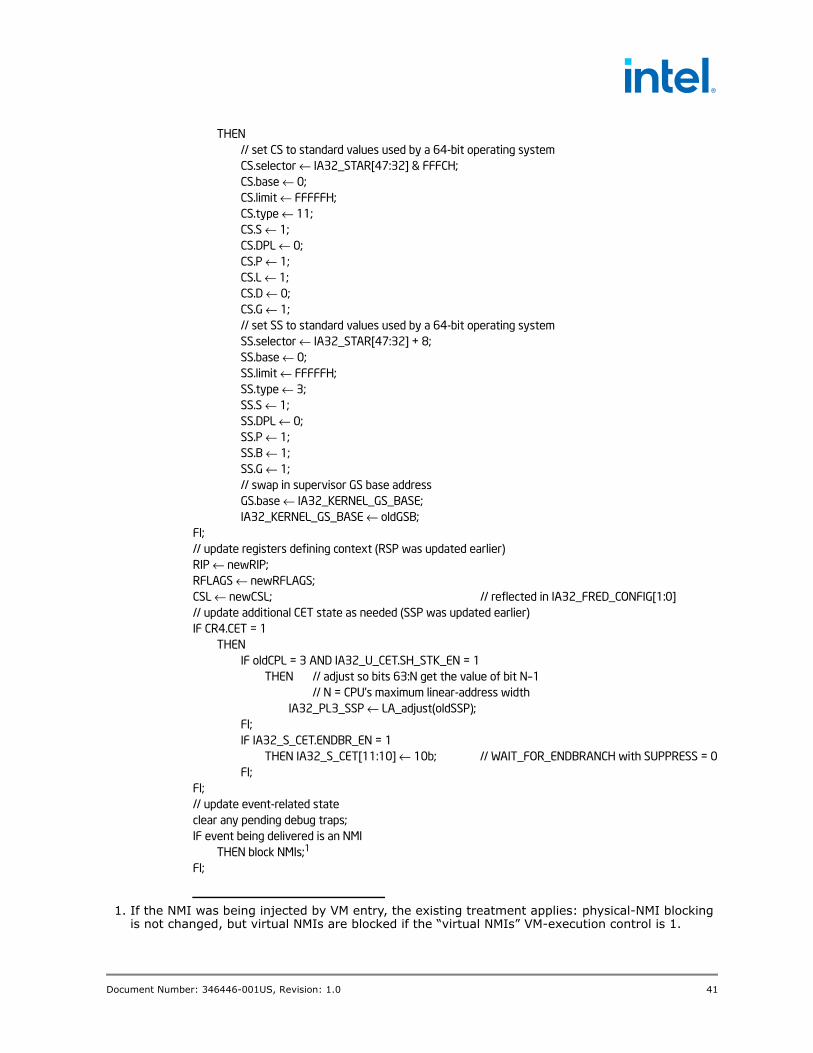
Document Number: 346446-001US, Revision: 1.0 41
THEN// set CS to standard values used by a 64-bit operating systemCS.selector ← IA32_STAR[47:32] & FFFCH;CS.base ← 0;CS.limit ← FFFFFH;CS.type ← 11;CS.S ← 1;CS.DPL ← 0;CS.P ← 1;CS.L ← 1;CS.D ← 0;CS.G ← 1;// set SS to standard values used by a 64-bit operating systemSS.selector ← IA32_STAR[47:32] + 8;SS.base ← 0;SS.limit ← FFFFFH;SS.type ← 3;SS.S ← 1;SS.DPL ← 0;SS.P ← 1;SS.B ← 1;SS.G ← 1;// swap in supervisor GS base addressGS.base ← IA32_KERNEL_GS_BASE;IA32_KERNEL_GS_BASE ← oldGSB;
FI;// update registers defining context (RSP was updated earlier)RIP ← newRIP;RFLAGS ← newRFLAGS;CSL ← newCSL; // reflected in IA32_FRED_CONFIG[1:0]// update additional CET state as needed (SSP was updated earlier)IF CR4.CET = 1
THENIF oldCPL = 3 AND IA32_U_CET.SH_STK_EN = 1
THEN // adjust so bits 63:N get the value of bit N–1// N = CPU’s maximum linear-address width
IA32_PL3_SSP ← LA_adjust(oldSSP);FI;IF IA32_S_CET.ENDBR_EN = 1
THEN IA32_S_CET[11:10] ← 10b; // WAIT_FOR_ENDBRANCH with SUPPRESS = 0FI;
FI;// update event-related stateclear any pending debug traps;IF event being delivered is an NMI
THEN block NMIs;1
FI;
1. If the NMI was being injected by VM entry, the existing treatment applies: physical-NMI blocking is not changed, but virtual NMIs are blocked if the “virtual NMIs” VM-execution control is 1.

42 Document Number: 346446-001US, Revision: 1.0
CPL ← 0;
A.2 Detailed Operation of ERETSThe appendix presents detailed pseudocode for the operation of ERETS:
IF IA32_EFER.LMA = 0 OR CS.L = 0 OR CR4.FRED = 0 OR CPL > 0THEN #UD;
FI;// pop old context from regular stack and check itpop8B newRIP;pop8B newCS;pop8B newRFLAGS;pop8B newRSP;pop8B newSS; // not usedIF newRIP is not canonical relative to the current paging mode OR
newCS[63:26] ≠ 0 OR newCS[23:19] ≠ 0 ORnewRFLAGS & FFFFFFFFFFC2802AH ≠ 2 OR newSS[63:16] ≠ 0// flags check enforces bit 1 is set and VM bit and all reserved bits are clear
THEN #GP(0);FI;NMI_unblock ← newCS[16];pend_DB ← newCS[17];STI_block← newCS[18];// ERETS will not numerically increase stack levelnewCSL ← min{CSL,newCS[25:24]};// If supervisor shadow stacks are enabled, pop and check values from the shadow stackIF CR4.CET = 1 AND IA32_S_CET.SH_STK_EN = 1
THENIF SSP & 7 ≠ 0 // require 8-byte alignment
THEN #CP(FAR-RET/IRET);FI;popSS_8B newSSP;popSS_8B checkSSLIP;popSS_8B checkSSCS;IF checkSSCS ≠ CS // 64-bit compare
OR checkSSLIP ≠ newRIPOR newSSP & 3H ≠ 0THEN #CP(FAR-RET/IRET);
FI;IF newSSP not canonical relative to current paging mode
THEN #GP(0);FI;
FI;// If supervisor shadow stacks are enabled, the stack level is changing, and// the FRED SSP MSR for the old stack level is not verified,// check token on shadow stack; in this section, i = CSLIF CR4.CET = 1 AND IA32_S_CET.SH_STK_EN = 1 AND
newCSL < CSL AND IA32_FRED_SSPi ≠ SSP | 1THEN

Document Number: 346446-001US, Revision: 1.0 43
IF IA32_FRED_SSPi = SSP // MSR has right address but isn’t verifiedTHEN
SSPToken ← 8 bytes at SSP;// no lockIF SSPToken = SSP | 1 // token busy, re-verify MSR
THEN // set bit 0 in MSR, marking it verifiedIA32_FRED_SSP ← SSPToken;
FI;ELSE // MSR has wrong address
SSPToken ← 8 bytes at SSP;// under lockIF SSPToken = SSP | 1
THEN store SSP at SSP; // unlock; clears bit 0, freeing tokenELSE store SSPToken at SSP;// unlock; memory not changed
FI;FI;
FI;// update registers for return contextRIP ← newRIP;RFLAGS ← newRFLAGS; // ERETS can set RFLAGS.RF to 1RSP ← newRSP;CSL ← newCSL; // reflect in IA32_FRED_CONFIG[1:0]IF CR4.CET = 1 AND IA32_S_CET.SH_STK_EN = 1
THEN SSP ← newSSP;FI;// update event-related stateIF NMI_unblock = 1
THEN unblock NMIs;1
FI;IF pend_DB = 1 AND RFLAGS.TF =1
THEN pend a single-step debug exception (#DB) to be delivered after ERETS;2
FI;IF STI_unblock = 1
THEN esablish STI blocking;FI;
A.3 Detailed Operation of ERETUThe appendix presents detailed pseudocode for the operation of ERETU:
IF IA32_EFER.LMA = 0 OR CS.L = 0 CR4.FRED = 0 OR CPL > 0THEN #UD;
FI;// pop old context from regular stack and check itpop8B newRIP;pop8B tempCS;pop8B newRFLAGS;pop8B newRSP;
1. If in VMX non-root operation with the 1-setting of the “virtual NMIs” VM-execution control, this step unblocks virtual NMIs. See Section 9.
2. If ERETS began execution with RFLAGS.TF = 1, there will always be a single-step debug exception pending after ERETS, regardless of the values on the stack for RFLAGS.TF and CS.

44 Document Number: 346446-001US, Revision: 1.0
pop8B tempSS;IF tempCS[63:18] ≠ 0 OR newRFLAGS & FFFFFFFFFFC2B02AH ≠ 2 OR tempSS[63:16] ≠ 0
// the flags check enforces that bit 1 is set and that IOPL, the VM bit and all reserved bits are clearTHEN #GP(0);
FI;NMI_unblock ← tempCS[16];pend_DB ← tempCS[17];IF tempCS[15:0] = IA32_STAR[63:48] + 16 AND
tempSS[15:0] = IA32_STAR[63:48] + 8THEN // Return to ring 3 in standard 64-bit configuration
// set newCS to standard values used ring 3 in 64-bit modenewCS.selector ← (IA32_STAR[63:48] + 16) | 3;newCS.base ← 0;newCS.limit ← FFFFFH;newCS.type ← 11;newCS.S ← 1;newCS.DPL ← 3;newCS.P ← 1;newCS.L ← 1;newCS.D ← 0;newCS.G ← 1;
// set newSS to standard values for ring 3newSS.selector ← (IA32_STAR[63:48] + 8) | 3;newSS.base ← 0;newSS.limit ← FFFFFH;newSS.type ← 3;newSS.S ← 1;newSS.DPL ← 3;newSS.P ← 1;newSS.B ← 1;newSS.G ← 1;
ELSIF tempCS[15:0] = IA32_STAR[63:48] ANDtempSS[15:0] = IA32_STAR[63:48] + 8
THEN// set newCS to standard values used ring 3 in compatibility mode
newCS.selector ← IA32_STAR[63:48] | 3;newCS.base ← 0;newCS.limit ← FFFFFH;newCS.type ← 11;newCS.S ← 1;newCS.DPL ← 3;newCS.P ← 1;newCS.L ← 0;newCS.D ← 1;newCS.G ← 1;
// set newSS to standard values for ring 3newSS.selector ← (IA32_STAR[63:48] + 8) | 3;newSS.base ← 0;newSS.limit ← FFFFFH;newSS.type ← 3;

Document Number: 346446-001US, Revision: 1.0 45
newSS.S ← 1;newSS.DPL ← 3;newSS.P ← 1;newSS.B ← 1;newSS.G ← 1;
ELSE IF tempCS[1:0] ≠ 3 // ERETU only to ring 3
THEN #GP(0);FI;load newCS using tempCS[15:0]; // load each as is done by IRET;load newSS using tempSS[15:0]; // checks that may lead to faultIF newCS.L = 0 AND newRIP is not within newCS’s limit
THEN #GP(0);FI;
FI;IF newCS.L = 1 AND newRIP is not canonical relative to current paging mode
THEN #GP(0);FI;// If supervisor shadow stacks are enabled, SSP must be 8-byte alignedIF CR4.CET = 1 AND IA32_S_CET.SH_STK_EN = 1 AND SSP & 7 ≠ 0
THEN #CP(FAR-RET/IRET);FI;// If user shadow stacks are enabled, check new SSP valueIF CR4.CET = 1 AND IA32_U_CET.SH_STK_EN = 1 AND
(newCS.L = 0 AND IA32_PL3_SSP[63:32] ≠ 0)// return to compatibility modeOR (newCS.L = 1 AND IA32_PL3_SSP not canonical relative to paging mode)
THEN #GP(0);FI;// If supervisor shadow stacks are enabled and the FRED SSP MSR for// the FRED SSP MSR for the CSL is not verified,// check token on shadow stack; in this section, i = CSLIF CR4.CET = 1 AND IA32_S_CET.SH_STK_EN = 1 AND IA32_FRED_SSPi ≠ SSP | 1
THENIF IA32_FRED_SSPi = SSP // MSR has right address but isn’t verified
THENSSPToken ← 8 bytes at SSP;// no lockIF SSPToken = SSP | 1 // token busy, re-verify MSR
THEN // set bit 0 in MSR, marking it verifiedIA32_FRED_SSP ← SSPToken;
FI;ELSE // MSR has wrong address
SSPToken ← 8 bytes at SSP;// under lockIF SSPToken = SSP | 1
THEN store SSP at SSP; // unlock; clears bit 0, freeing tokenELSE store SSPToken at SSP;// unlock; memory not changed
FI;FI;
FI;// update registers for return contextRIP ← newRIP;

46 Document Number: 346446-001US, Revision: 1.0
RFLAGS ← newRFLAGS; // ERETU can set RFLAGS.RF to 1RSP ← newRSP; // load all 64 bits regardless of new modeCS ← newCS; // selector and descriptorSS ← newSS; // selector and descriptorCPL ← 3;tempGSB ← GS.base; // swap GS.base and IA32_KERNEL_GS_BASEGS.base ← IA32_KERNEL_GS_BASE;IA32_KERNEL_GS_BASE ← tempGSB;CSL ← 0; // reflect in IA32_FRED_CONFIG[1:0]IF CR4.CET = 1 AND IA32_U_CET.SH_STK_EN = 1
THEN SSP ← IA32_PL3_SSP;FI;// update event-related stateIF NMI_unblock = 1
THEN unblock NMIs; 1
FI;IF pend_DB = 1 AND RFLAGS.TF =1
THEN pend a single-step debug exception (#DB) to be delivered after ERETU;2
FI;
1. If in VMX non-root operation with the 1-setting of the “virtual NMIs” VM-execution control, this step unblocks virtual NMIs. See Section 9.
2. If ERETU began execution with RFLAGS.TF = 1, there will always be a single-step debug exception pending after ERETU, regardless of the values on the stack for RFLAGS.TF and CS.