flexible multi-numerology systems for 5g new radio · where each numerology consists of a set of...
TRANSCRIPT

Flexible Multi-Numerology Systemsfor 5G New Radio
Ahmet Yazar1,∗ and Huseyin Arslan1,2
1Istanbul Medipol University, Istanbul, 34810 Turkey2University of South Florida, Tampa, FL 33620 USAE-mail: [email protected]; [email protected]∗Corresponding Author
Received 1 August 2018; Accepted 06 September 2018;Publication 20 September 2018
Abstract
The physical layer of 5G cellular communications systems is designed toachieve better flexibility in an effort to support diverse services and userrequirements. Orthogonal frequency division multiplexing (OFDM) wave-form parameters are enriched with flexible multi-numerology structures. Thispaper gives a short summary for the Third Generation Partnership Project(3GPP) New Radio (NR) standard and then describes the differences ofbuilding blocks for Long Term Evolution (LTE) systems and NR from theflexibility perspective. Research opportunities for multi-numerology systemsare presented in a structured manner. Finally, inter-numerology interference(INI) and signal-to-interference ratio (SIR) results as a function of multi-numerology parameters, guard allocation and user power levels are obtainedthrough computer simulations.
Keywords: 3GPP, 5G, adaptive scheduling, flexibility, multi-numerology,New Radio, OFDM, waveform.
Journal of Mobile Multimedia, Vol. 14 4, 367–394.doi: 10.13052/jmm1550-4646.1442c© 2018 River Publishers

368 A. Yazar and H. Arslan
1 Introduction
Long Term Evolution (LTE) waveform has a fixed structure that is optimizedto serve high data rate applications [1]. There is only limited support for otherapplications due to the inflexibility of the waveform and LTE cannot supportthe rich service and user requirements of 5G vision [2]. 5G New Radio (NR) isaimed to provide wide variety of services by rendering waveform parametersflexibly [3]. The new design paradigms make enhanced-mobile broadband(eMBB) experience possible everywhere. The flexibilities introduced to thewaveform and frame enable reduced latencies and improved reliability,empowering ultra reliable and low latency communications (uRLLC) inaddition to high data rate applications. Moreover, massive machine typecommunications (mMTC) is enabled for suitable scenarios with NR.
5G flexibility is provided by the coexistence of multiple numerologies,where each numerology consists of a set of parameters defining the frameand lattice structure of the waveform. The same single mother waveformorthogonal frequency division multiplexing (OFDM) is employed for bothLTE and NR but in contrast to the single-numerology utilization in LTE, NRallows simultaneous multi-numerology utilization [4].
Different numerologies are multiplexed orthogonally in time domainin [5]. It is one of the first studies that incorporated multi-numerology ormixed-numerology systems and designed a framework that provides numer-ous services simultaneously in a unified frame. Multiple numerologies aremultiplexed in both time and frequency domains with 5G NR [6].
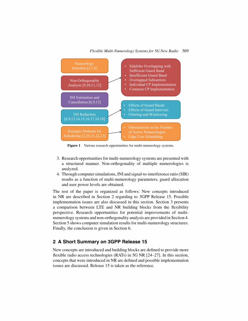
Multi-numerology structures that were included in the Third GenerationPartnership Project (3GPP) NR standardization were studied in literaturefrom different aspects. Relationships between multiple numerologies anduser/service requirements are provided in [2, 7, 8] from the numerologyselection perspective. Non-orthogonality of multi numerologies are inves-tigated in [9–12]. Various inter-numerology interference (INI) estimation andcancellation methods are provided in [6, 9, 13]. Moreover, INI reductiontechniques are proposed in [6,9,13–19]. Algorithm examples for the advancedscheduling methods of multiple numerologies explained in [2, 20–23]. Asummary for the subjects of these studies are presented in Figure 1 and detailsfor the literature are provided in Section 4.
In this paper, four main contributions have been made as listed below:
1. New concepts introduced in NR are described regarding to 3GPP Release15 and possible implementation issues are discussed.
2. Building blocks of LTE and NR were compared from the flexibilityperspective regarding to 3GPP 38-series standardization documents.
Flexible Multi-Numerology Systems for 5G New Radio 369
NumerologySelection [2,7,8]
Non-OrthogonalityAnalysis [9,10,11,12]
INI Estimation andCancellation [6,9,13]
INI Reduction[6,9,13,14,15,16,17,18,19]
Example Methods forScheduling [2,20,21,22,23]
• Sidelobe Overlapping withSufficient Guard Band
• Insufficient Guard Band• Overlapped Subcarriers• Individual CP Implementation• Common CP Implementation
• Effects of Guard Bands• Effects of Guard Intervals• Filtering and Windowing
• Optimization on the Numberof Active Numerologies
• Edge User Scheduling
Figure 1 Various research opportunities for multi-numerology systems.
3. Research opportunities for multi-numerology systems are presented witha structured manner. Non-orthogonality of multiple numerologies isanalyzed.
4. Through computer simulations, INI and signal-to-interference ratio (SIR)results as a function of multi-numerology parameters, guard allocationand user power levels are obtained.
The rest of the paper is organized as follows: New concepts introducedin NR are described in Section 2 regarding to 3GPP Release 15. Possibleimplementation issues are also discussed in this section. Section 3 presentsa comparison between LTE and NR building blocks from the flexibilityperspective. Research opportunities for potential improvements of multi-numerology systems and non-orthogonality analysis are provided in Section 4.Section 5 shows computer simulation results for multi-numerology structures.Finally, the conclusion is given in Section 6.
2 A Short Summary on 3GPP Release 15
New concepts are introduced and building blocks are defined to provide moreflexible radio access technologies (RATs) in 5G NR [24–27]. In this section,concepts that were introduced in NR are defined and possible implementationissues are discussed. Release 15 is taken as the reference.
370 A. Yazar and H. Arslan
In 3GPP Release 15, standalone (SA) operation according to [28, 29]and non-SA (NSA) operation coexisting with other technologies accordingto [30] are defined. NSA operation was finalized in Release 15, but someissues regarding SAoperation, along with details necessary to provide mMTC,was left for further study to be finalized in Release 16 that is expected to becompleted in in the first quarter of 2020.
Waveform defines how the resources are placed in the time-frequencylattice and the structure (pulse shapes and filters) that maps informationsymbols to these resources [5]. In the downlink (DL), NR uses (CP)-OFDMwith multi numerologies (a mother waveform plus its derivatives). In theuplink (UL), there is an option to use either of CP-OFDM and discrete Fouriertransform (DFT)-spread-OFDM (DFT-s-OFDM) with multi numerologies forNR [31].
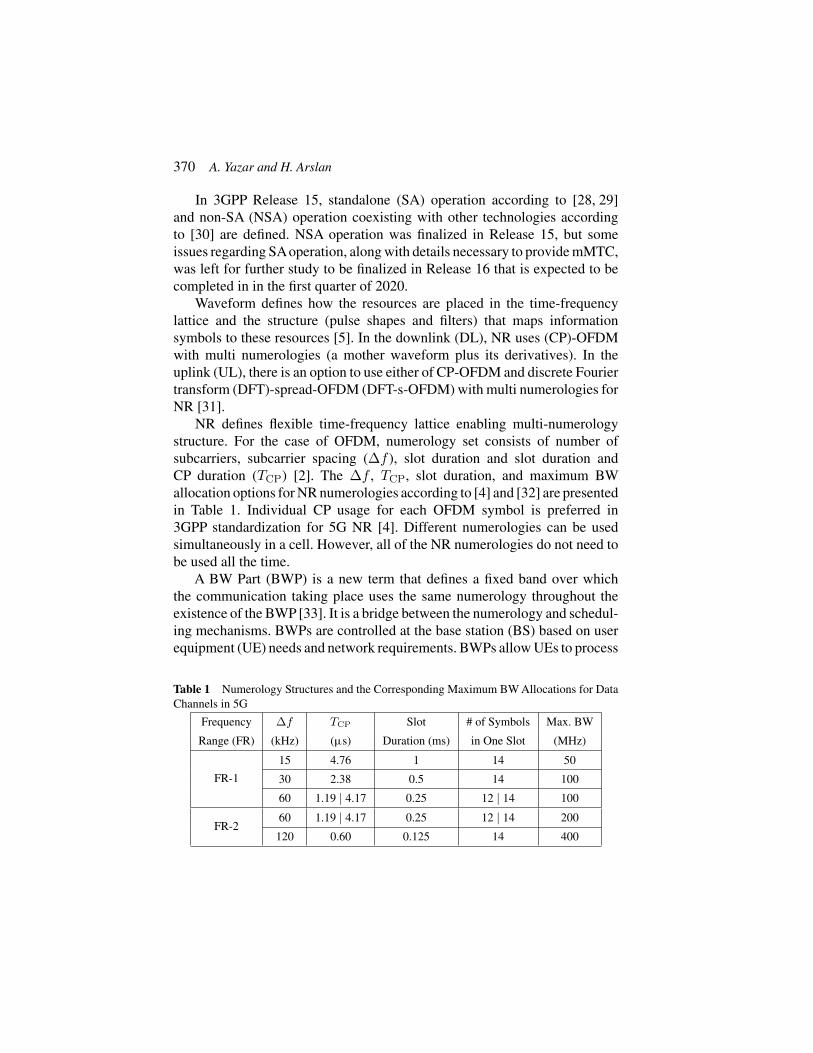
NR defines flexible time-frequency lattice enabling multi-numerologystructure. For the case of OFDM, numerology set consists of number ofsubcarriers, subcarrier spacing (Δf ), slot duration and slot duration andCP duration (TCP) [2]. The Δf , TCP, slot duration, and maximum BWallocation options for NR numerologies according to [4] and [32] are presentedin Table 1. Individual CP usage for each OFDM symbol is preferred in3GPP standardization for 5G NR [4]. Different numerologies can be usedsimultaneously in a cell. However, all of the NR numerologies do not need tobe used all the time.
A BW Part (BWP) is a new term that defines a fixed band over whichthe communication taking place uses the same numerology throughout theexistence of the BWP [33]. It is a bridge between the numerology and schedul-ing mechanisms. BWPs are controlled at the base station (BS) based on userequipment (UE) needs and network requirements. BWPs allow UEs to process
Table 1 Numerology Structures and the Corresponding Maximum BW Allocations for DataChannels in 5G
Frequency Δf TCP Slot # of Symbols Max. BW
Range (FR) (kHz) (μs) Duration (ms) in One Slot (MHz)
FR-1
15 4.76 1 14 50
30 2.38 0.5 14 100
60 1.19 | 4.17 0.25 12 | 14 100
FR-260 1.19 | 4.17 0.25 12 | 14 200
120 0.60 0.125 14 400

Flexible Multi-Numerology Systems for 5G New Radio 371
only part of the band that contain their symbols, reducing power consumptionand enabling longer battery lives. This is very useful for the low-power com-munications systems, particularly mMTC services. NR allows overlapping ofBWPs using different numerologies in time-frequency grid [24]. BWPs mayoverlap to facilitate low latency services while providing data to noncriticalservices to ensure efficient utilization of resources. BWP is a practical toolfor multi-numerology systems as BWP defines a specific numerology. BS canmodify UE numerologies by changing it’s BWPs. Parameter configurationprocess for the BWPs is employed by BW adaptation (BA) tool on BS [34].There can be up to four defined BWPs for each UE but there is one activeBWP for each user in Release 15. However, future NR releases are planned toallow multiple (up to four per UE in Release 16) active BWP configurations.Although not imposed by the standard [4], it is generally preferred that BWPsconfigured to use the same numerologies consecutively in an effort to reduceguard bands and computational complexity.
BS channel BW is another new term that refers to the contiguous BWcurrently in use by the next generation node B (gNB) for either transmissionor reception [35]. In other words, it refers to the total BW that is processed bythe gNB.
NR slots can consist of 14 symbols forΔfs up to 60 kHz [36]. Furthermore,NR Resource Blocks (RBs) are defined only using the same BW definition;their durations are not fixed [4]. NR Transmission Time Interval (TTI) may bea mini-slot in the case of uRLLC or beam-sweeping operation in frequencyrange-2, a slot for regular operation, or multiple slots in the case of largenumber of eMBB packets [36]. The number of slots per sub-frame dependson the Δf and is given by the multiplicative inverse of the slot durationseen in Table 1 [4]. Various slot configurations and UE scheduling guidelinesreveal that few restrictions exist regarding scheduling users in time domain.This implies that the guard times can also be utilized flexibly, similar to guardbands. Combining time-frequency guard flexibility yields that empty resourceelements can virtually be placed anywhere.
In 3GPP standards, it is revealed that there are minimum guard bandrequirements, a maximum or an optimum value is not enforced, makingguard bands choices flexible with high granularity [35].Additionally, applyingproper filtering and windowing methods are left for the implementation in3GPP standardization. Spectral guards and pulse shapes are critical part of theNR flexibility. These are left for the implementation as long as it is transparentto the counterpart of the communications.

372 A. Yazar and H. Arslan
For NR, 3GPP standards give freedom to implement any additionalalgorithms that BS and UE manufacturers desire as long as it is transparentto the receiver [37]. Various details for possible implementation issues arediscussed in Section 4.
3 Flexibility Comparison for Building Blocks of 5G NRand LTE
In this section, the differences of building blocks for LTE and NR aredistinguished from the flexibility perspective.
LTE and NR use the same mother waveform but there is only onenumerology in LTE. In the UL, the only option in LTE is DFT-s-OFDM witha single numerology. However, there is an option to use either of CP-OFDMand DFT-s-OFDM with multi numerologies for NR.
LTE used a fixed lattice in which the frequency (and corresponding time)spacing between each point was always the same throughout the wholetransmission band [3]. LTE is a single-numerology system thus all theseparameters are fixed at all times for a BS. On the contrary, NR defines flexibletime-frequency lattice enabling multi-numerology structure.
In contrast to LTE, 5G UEs do not need to monitor the whole transmissionBW; they only scan the BWPs assigned to themselves.
Unlike LTE slots that consist of 7 OFDM symbols in case of normal CP,NR slots can consist of 14 symbols for Δfs up to 60 kHz [36]. Furthermore,LTE RBs cover 12 consecutive subcarriers over a subframe (i.e., two slots)duration, whereas NR RBs are defined only using the same BW definition;their durations are not fixed [4]. As opposed to the fixed LTE TTI durationof one slot, NR TTI may be a mini-slot. NR re-uses the LTE radio framedefinition [38], however, the number of slots per sub-frame depends on theΔf and is given by the multiplicative inverse of the slot duration seen inTable 1 [4].
4 Research Opportunities for Multi-Numerology Systems
As it can be seen from the previous sections, the main flexibility causative forNR is mostly focused on the new frame with multi-numerology. Different UEand service requirements can be met using multiple numerologies. In otherwords, multiplexing numerologies provides the flexibility needed by NR.
Flexible Multi-Numerology Systems for 5G New Radio 373
This section presents various research opportunities and exemplary multi-numerology methods that exploit the flexibilities in NR design pointed outin the previous sections. Many new research studies exploit this degree offreedom.
4.1 Numerology Selection Methodologies
Numerologies of UEs cannot be decided arbitrarily. There is a need for anumerology selection mechanism to employ multi-numerology systems withmulti UEs. In this subsection, we provide some details on that subject.
Active BWPs and the corresponding numerologies can be selected usingdifferent methodologies. Various trade-offs between distinct performancemetrics that include spectral efficiency, INI, flexibility, and complexity canbe considered while deciding on active BWPs and so numerologies.
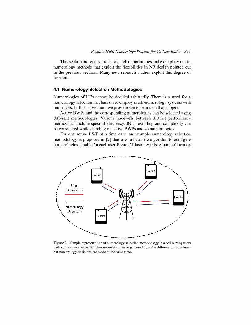
For one active BWP at a time case, an example numerology selectionmethodology is proposed in [2] that uses a heuristic algorithm to configurenumerologies suitable for each user. Figure 2 illustrates this resource allocation
Figure 2 Simple representation of numerology selection methodology in a cell serving userswith various necessities [2]. User necessities can be gathered by BS at different or same timesbut numerology decisions are made at the same time.

374 A. Yazar and H. Arslan
optimization methodology. The proposed method also provides an active BWPswitching mechanism. Δf , TCP, and spectral efficiency requirements of allusers in a cell are input to the algorithm.
It is possible to increase the number of numerologies in beyond 5G.Offering more numerologies simultaneously ensures that all user and servicerequirements are satisfied, but this requires more sophisticated numerologyselection mechanisms. To reduce computational costs, BSs may use two-stepnumerology selection methods in the future. The first step decides on themost suitable numerology set between different sets. Then, the second stepdetermines the best numerologies from the set that is selected in the first step.Additionally, different numerology selection methods may become availablefor multiple BWPs active at a time case.
In [21], a heuristic solution is proposed while considering the optimizationof the data block allocation as a Knapsack problem. In the future, opti-mal numerology assignment methodology can be developed for multiplenumerology systems using the Knapsack problem approachment.
4.2 Non-Orthogonality in Multi Numerologies
In this subsection, different implementation structures are presented in thescope of non-orthogonality in multiple numerologies. INI changes tremen-dously regarding the non-orthogonality under different implementations.
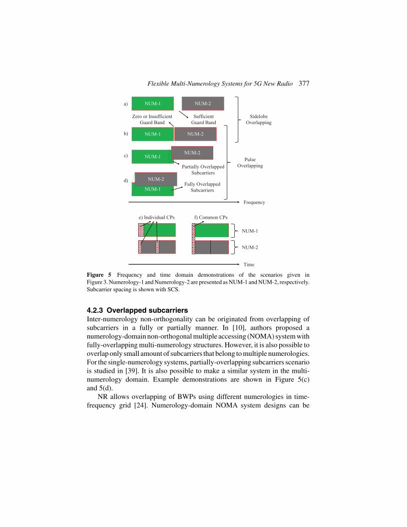
Relationships between different scenarios for inter-numerologies aresummarized in Figure 3. Synchronous communications means there is a slot-based synchronicity. In addition, overlapping of multiple numerologies ispulse-based and sidelobe-based. If there is a non-orthogonality for the edgesubcarriers, there can be full or partial orthogonality for the inner subcar-riers of multiple numerologies. Here we assume that non-orthogonality ofinter-numerologies need to be analyzed for each of the subcarriers separately.
Implementation methods are presented in Figure 4. Also, exampledemonstrations are shown in Figure 5.
4.2.1 Sidelobe overlapping with sufficient guard bandNon-orthogonality can result either from pulse-based or sidelobe-based over-lapping numerologies for the synchronous communications. In the case ofsidelobe overlapping subcarriers, the main reason of non-orthogonality is out-of-band (OOB) emission. We can use large guard bands between differentnumerologies to move away from the spectral leakage and reduce INI.

Flexible Multi-Numerology Systems for 5G New Radio 375
SynchronousCommunications
Pulse Overlapping(Inter-Numerologies)
Sidelobe Overlapping(Inter-Numerologies)
Non-Orthogonal
AsynchronousCommunications
Non-Orthogonal
Sufficient Guards(Sec. 3.2.1, Fig. 5a)
Insufficient Guards(Sec. 3.2.2, Fig. 5b)
Common CPImplementation
(Sec. 3.2.5, Fig. 5f)
Individual CPImplementation
(Sec. 3.2.4, Fig. 5e)
Orthogonal
Non-OrthogonalPartly-Orthogonal
for NUM-1 (Fig. 9)Non-Orthogonal
for NUM-2
Single-Numerology(LTE)
Multi-Numerology (5G)
Orthogonal
Overlapping of Subcarriers(Inter-Numerologies)
(Sec. 3.2.3, Fig. 5c and 5d)
Most of theCurrent
5G Research
Research Gapfor 5G and Beyond
Figure 3 Non-orthogonality and partial orthogonality of inter-numerologies for differentOFDM-based scenarios. NUM-1 has narrow subcarriers and NUM-2 has wider subcarriers.
Resource elements within the same numerology are orthogonal to each other,but resource elements of any two numerologies with different Δfs are onlyorthogonal to each other if sufficient guards exist among them [9, 17].
Effects of guard bands are mentioned in Section 4.4 and the relatedperformance analysis results are given in Section 5.2. Deciding about therequired guard bands between multiple numerologies for different scenariosis an important research area. The amount of guard bands affects spectralefficiency inversely proportional.
4.2.2 Insufficient guard bandIf the guard amount between multiple numerologies is insufficient or it is azero-guard case [17], inter-numerology non-orthogonality is inevitable. Mostof the studies for the 5G multi-numerology systems can be classified underthis scenario.
OOB emission increase INI effects especially for the edge subcarriersof each numerologies. Side lobes decrease from edge to inner subcarriers

376 A. Yazar and H. Arslan
…
-pointIFFT for∆
SubcarrierSpacing
/(2 )-pointIFFT for2 × ∆
SubcarrierSpacing
NotUsed
InformationSymbols
OFDM Symbolwith Samplesin Time Domain
OFDM Symbolwith / 2 Samples
in Time Domain
Transmitting(1 + ) Samples
in Time Domain
-pointFFT for∆
SubcarrierSpacing
/ 2 -pointFFT for
2 × ∆
SubcarrierSpacing
2 SubblocksOne by One
ReceivedSymbols
ReceivedSymbols
CP Addition forEach Symbol
with Ratio
CP Addition forEach Symbol
with Ratio
RemoveCP
RemoveCP
2 OFDM Symbols
InformationSymbols
GuardBand
NotUsed
GuardBand
(a) There is a guard band between numerologies. Individual CPs are preferred.
…
-pointIFFT for∆
SubcarrierSpacing
/(2 )-pointIFFT for2 × ∆
SubcarrierSpacing
NotUsed
NotUsed
InformationSymbols
OFDM Symbolwith Samplesin Time Domain
OFDM Symbolwith / 2 Samples
in Time Domain
Transmitting(1 + ) Samples
in Time Domain
-pointFFT for∆
SubcarrierSpacing
/ 2 -pointFFT for
2 × ∆
SubcarrierSpacing
2 SubblocksOne by One
ReceivedSymbols
ReceivedSymbols
CommonCP Addition
RemoveCommon
CP
2 OFDM Symbols
InformationSymbols
RemoveCommon
CP
(b) There is not any guard band between numerologies. Common CP is preferred.
Figure 4 Block diagram for the simple implementation of multi numerologies. The scalingfactor of Δfs is chosen as 2k, where k is a positive integer.
in all multi-numerology scenarios. Additionally, separation of the compositesignal at the receiver unintentionally increase INI during the separation of thecomposite signal. This situation is discussed more in the next subsections.
Different CP implementation techniques can be employed to decrease INIeffects in the scenarios that have insufficient guards. Moreover, alternativeINI reduction techniques like filtering and windowing can be preferred asmentioned in Section 4.4. It is also possible to use advanced schedulingtechniques like in Section 4.5.
Flexible Multi-Numerology Systems for 5G New Radio 377
Time
e) Individual CPs f) Common CPs
NUM-1
NUM-2
Zero or InsufficientGuard Band
NUM-1 NUM-2
NUM-1 NUM-2
NUM-1NUM-2
a)
b)
c)
Frequency
SidelobeOverlapping
PulseOverlapping
SufficientGuard Band
Partially OverlappedSubcarriers
NUM-1
NUM-2d)Fully Overlapped
Subcarriers
Figure 5 Frequency and time domain demonstrations of the scenarios given inFigure 3. Numerology-1 and Numerology-2 are presented as NUM-1 and NUM-2, respectively.Subcarrier spacing is shown with SCS.
4.2.3 Overlapped subcarriersInter-numerology non-orthogonality can be originated from overlapping ofsubcarriers in a fully or partially manner. In [10], authors proposed anumerology-domain non-orthogonal multiple accessing (NOMA) system withfully-overlapping multi-numerology structures. However, it is also possible tooverlap only small amount of subcarriers that belong to multiple numerologies.For the single-numerology systems, partially-overlapping subcarriers scenariois studied in [39]. It is also possible to make a similar system in the multi-numerology domain. Example demonstrations are shown in Figure 5(c)and 5(d).
NR allows overlapping of BWPs using different numerologies in time-frequency grid [24]. Numerology-domain NOMA system designs can be

378 A. Yazar and H. Arslan
developed to exploit this gap in 5G. However, receiver complexity increasefor the scenarios with the overlapped subcarriers.
Besides these scenarios, subcarriers are non-orthogonal to each other forintra- or inter-numerology domains in asynchronous communications [12].
4.2.4 Individual CP implementationCP implementation techniques have effects on non-orthogonality in multinumerologies [9–11]. Individual CPusage for each OFDM symbol is preferredin 3GPP standardization for 5G NR [4]. However, there is an importantdisadvantage of employing individual CPs.
A composite signal is formed with summing time domain signals ofdifferent numerologies at the end of transmitter side as shown in Figure 4(a).There are more than one symbol for the shorter symbol duration numerologiescorresponding to one symbol of the other numerology that has a longer symbolduration as shown in Figure 5(e). Therefore, CPs of the shorter symbol durationnumerologies corrupt orthogonality of long symbol duration numerologyduring Fourier transform (FFT) process at the receiver side.
4.2.5 Common CP implementationFor the common CP usage, a composite signal is formed with summing timedomain signals of different numerologies before CP addition process as shownin Figures 4(b) and 5(f). One CP is added to the composite signal at the end oftransmitter. Hence, the disadvantage of employing individual CPs is preventedbecause orthogonality is not corrupted during FFT process at the receiver side.There is less INI because of the partial orthogonality for long symbol durationnumerology with the common CP implementation. However, there is not anydifference between two implementations regarding the short symbol durationnumerology.
Common CP also can be useful from the perspectives of spectral efficiencyand latency. Advantages of zero-interference subcarriers can be exploited fordifferent purposes like channel estimation. uRLLC users can be scheduled atthe short symbol duration numerology side with common CP implementationbecause there is less INI and this implementation provides more reliable com-munications. Moreover, latency can be reduced by using a shorter commonCP in suitable scenarios [40]. Based on all these advantages, it can be said thatcommon CP implementation may be one of the research areas for 5G beyondtechnologies. Additionally, common CP needs to be arranged according towireless channel of different UEs and common CP selection of multiple usersis also an important research area.

Flexible Multi-Numerology Systems for 5G New Radio 379
4.3 INI Estimation Models and Cancellation Methods
INI can be simply defined as a leakage between different numerology struc-tures. The amount of INI can vary depending on Δf , BW, guards, CP usagetype, filtering/windowing usage, and user power levels.All of these parametersneed to be analyzed together to form estimation models for INI. There aresome important studies about INI estimation in the literature but they do notinclude all of the aspects for the INI sources [6, 9]. In these studies, also INIcancellation methods are proposed to remove estimated INI at the receiver.
Authors of [9] shows that no-CP case can be used to estimate structuredINI. Common CP implementation can be considered as a similar scenarioas stated in Section 4.2. Structured INI can be exploited during the INIcancellation process. The analytical expression of the INI power is estab-lished for windowed OFDM systems in [6]. Another INI estimation methodbetween different transmitter and receiver windowed OFDM numerologiesare provided in [13], where the exact calculation of INI using the CIRs anddata of all users, as well as estimation techniques for practical cases such asunknown data as well as unknown CIRs are provided.
INI estimation can be used as a feedback to all other adaptive systems thatinclude numerology selection, adaptive guards, filtering/windowing decision,and advanced scheduling methods. Interference models can be very useful foradaptive decision on different algorithms for multi-numerology systems.
4.4 INI Reduction Techniques
Various INI reduction techniques that prevent INI and effects of them areexplained in this subsection. Effects of guards analyzed in [14, 17–19].Different filtering techniques are provided in [9,14–16]. Moreover, windowingmethods are discussed in [6, 13, 14].
4.4.1 Effects of guard bands between multi numerologiesThis subsection deals with the adjustment of frequency domain guards withrespect to estimated INI after numerologies are selected. In 3GPP standards,guard band choices can be flexible [35]. Adaptive guard band concept fordifferent numerologies becomes a crucial research area at this point.
As it is well known, the OFDM signal is well localized in the time domainwith a rectangular pulse shape, which corresponds to a sinc pulse in thefrequency domain. Sincs cause significant OOB emission and guard bandsare needed between two adjacent subbands with different numerologies tohandle the interference.
380 A. Yazar and H. Arslan
The OOB emission increases as the symbol duration decreases. Therefore,more guard band is required for the numerologies with higher Δf . For the edgesubcarriers of two adjacent numerologies, signal to interference plus noiseratio (SINR) decrease is more significant compared to the decrease in remain-ing subcarriers. Most of the interference comes from the edge subcarriers [41].Grouping services in BWPs reduces the amount of necessary guards andeases scheduling when such fast numerology variations become necessities.Moreover, passing OFDM signal through power amplifiers causes non-lineardistortions. The peak-to-average power ratio (PAPR) and OOB emissionincrease as the number of active subcarriers increases. As a result, more guardband is needed for the transmissions with wider occupied numerology BWs.
In Section 5, the effects of guard bands between multi numerologies withthe performance analysis results are shown regarding to the implementationblock diagram given in Figure 4(a).
4.4.2 Effects of guard intervals for INI eliminationIn addition to guard bands between different numerologies, the guards intime and frequency domains must be jointly optimized to boost the spectralefficiency [19]. The guard times can be utilized flexibly, similar to guardbands. Combining time-frequency guard flexibility yields that empty resourceelements can virtually be placed anywhere. Interpreting this at a multi-userlevel reveals that the UL slot of one UE and the DL slot of another UE can bescheduled to consecutive time or frequency resources with little guard timeand band. This poses serious requirements in pulse shaping, making localizedpulses and interference rejection techniques critical.
4.4.3 Filtering and windowing in NRINI cannot be handled only using guards but also with the filtering and win-dowing approaches that require additional guards. Applying proper filteringand windowing methods are left for the implementation of standardization.
Allocating users optimal guards minimizes but not completely eliminatesthe interference on the received signal in a non-orthogonal system. Thereceiver may also engage in filtering and windowing to further eliminate theremaining interference, but doing so using conventional methods requiresadditional guards. The assigned optimum guards may not be sufficient ifminimum latencies are required.
The algorithm presented in [13] deals with the minimization of aggregateinter-symbol interference (ISI), inter-carrier interference (ICI) and adjacentchannel interference (ACI) by windowing each received subcarrier with the

Flexible Multi-Numerology Systems for 5G New Radio 381
window function that minimizes the aggregate interference at that subcarrier.The optimal window lengths require perfect knowledge of the interferingusers’data and channels. While this can be known and applied at UL receptionat the gNB in a manner similar to successive interference cancellation (SIC)or multi-user (MU) detection, this cannot be done at the UE. Therefore, thealgorithm presents methods to estimate optimal subcarrier specific windowdurations if only the CIRs, power delay profiles (PDPs) or the power offsetsof the interferers are known.
4.5 Advanced Scheduling Techniques forMultiple Numerologies
4.5.1 Optimization on the number of active numerologiesAuthors of [2] find the efficient number of active numerologies that should besimultaneously employed by users. The algorithm aims to minimize variousoverheads to provide a practical solution satisfying different service and userrequirements using multi-numerology structures. All of the numerologies thatare defined in standards do not need to be used all the time.
Basically, the amount of total guard band in the lattice increases withincreasing number of numerologies. Hence, there is a trade-off betweenthe spectral efficiency and multi-numerology system flexibility. Althoughnot imposed by the standard [4], they allocate BWPs configured to use thesame numerologies consecutively in an effort to reduce guard bands andcomputational complexity.
4.5.2 Edge user scheduling for multiple numerologiesEdge users of multiple numerologies experience unfairness because most ofthe INI is concentrated at the edges of numerologies. Intensive INI at theedges causes low reliability for edge UEs. Proper scheduling mechanisms canincrease fairness and reliability for these UEs.
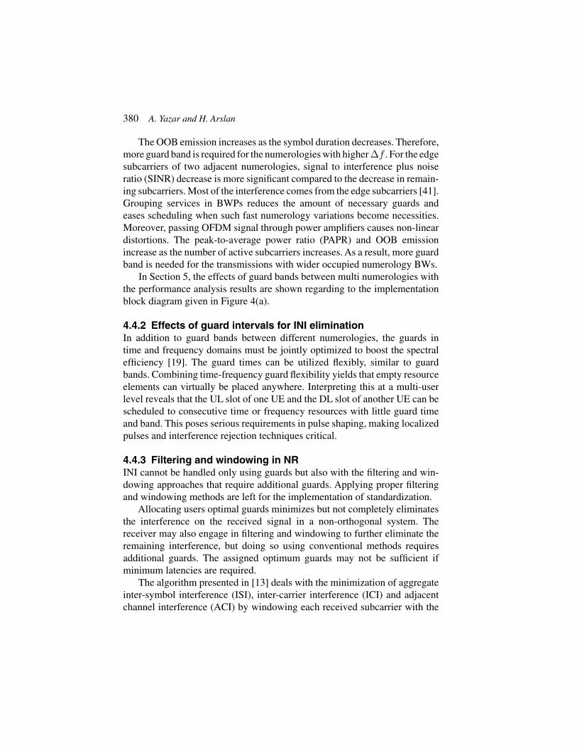
In [20], fairness of UEs at the numerology edges is increased by mini-mizing the INI effects while maintaining spectral efficiency with fixed guardbands. They use three inputs that include service type, power level, and BW of aUE. Their only focus is on edge UEs in the proposed algorithms. The other UEscan be scheduled randomly in frequency domain. Hence, frequency dependentscheduling flexibility does not lose. The main aim is that minimization ofthe power difference between edge users of multiple numerologies as shownin Figure 6. Performance analysis results for power difference scenarios areprovided in Section 5.4.
382 A. Yazar and H. Arslan
UE-1
UE-4 UE-5
BWPs with NUM #1
UE-3UE-2
UE-6
BWPs with NUM #2
UE-1
UE-4 UE-5
BWPs with NUM #1
UE-3UE-2
UE-6
BWPs with NUM #2
Random Scheduling:
Scheduling Algorithm:
Frequency
PL
Frequency
PLReschedule to decreasePO between edge users.
Figure 6 Example demonstration for the edge user scheduling algorithm. Power levels areshown with PL.
Contrary to [20], authors of [19] aim to minimize guard necessities witha fixed SIR and fairness in their scheduling algorithm. In their case, spectralefficiency can be increased due to the fewer guard necessities between differentnumerologies under desired SIR.
5 Simulation Results for Multi-Numerology Systems
In this section, various INI and SIR results as a function of multi-numerologyparameters, guard allocation and user power levels are provided throughcomputer simulations based on the block diagram in Figure 4.

Flexible Multi-Numerology Systems for 5G New Radio 383
5.1 Assumptions and System Model
It is assumed that UEs are synchronous to each other. We allocate UEsor BWPs with same numerologies contiguously in the frequency domain.It is also assumed that the subcarriers of UEs are sidelobe overlappedto each other and each numerology block that consists of multiple carri-ers is shared by multiple UEs. OFDM is employed and each UEs havedifferent power levels in Section 5.4 and equal power levels in othersubsections.
Independent random binary phase shift keying (BPSK) symbols are gener-ated separately for two-numerology structure. For the first numerology, whichhas Δfref kHz subcarrier spacing, N -point inverse fast Fourier transform(IFFT) is employed. The second numerology has 2k × Δfref kHz subcarrierspacing and uses N/(2k)-point IFFT, where 2k is the scaling factor and kis a positive integer. Here, the second half of the IFFT inputs for the firstnumerology and the first half of the IFFT inputs for the second numerologyare zero-padded to separate two numerologies in frequency domain. Aftereach IFFT operation, CP samples are added with a ratio of CPR to everyOFDM symbol. There are 2k OFDM symbols with the second numerologycorresponding to one OFDM symbol with the first numerology. Thus, thenumber of samples for each of the numerologies are the same, and they canbe added to form a composite signal at the transmitter.
Wireless channel and noise are ignored to just focus on the INI inthe simulation results. At the receiver side, CP samples are removedfrom each OFDM symbol. N -point FFT is used for the first numerologyover full composite signal. However, only N/(2k) samples of the com-posite signal to make them input into N/(2k)-point FFT for the secondnumerology. 2k subblocks are constituted by dividing the composite signalinto 2k parts and these subblocks are processed one by one. The firsthalf of the FFT output for the first numerology and the second half ofthe FFT output for the second numerology are taken to obtain receivedsymbols.
Interference estimations for each of the used subcarriers are done sepa-rately. Monte Carlo method is applied and the number of independent tests is500 with different set of random data in each of these tests. Thereafter, theaverage interference on the subcarriers are estimated.

384 A. Yazar and H. Arslan
5.2 Subcarrier Spacing and Guard Band Effects withIndividual CPs
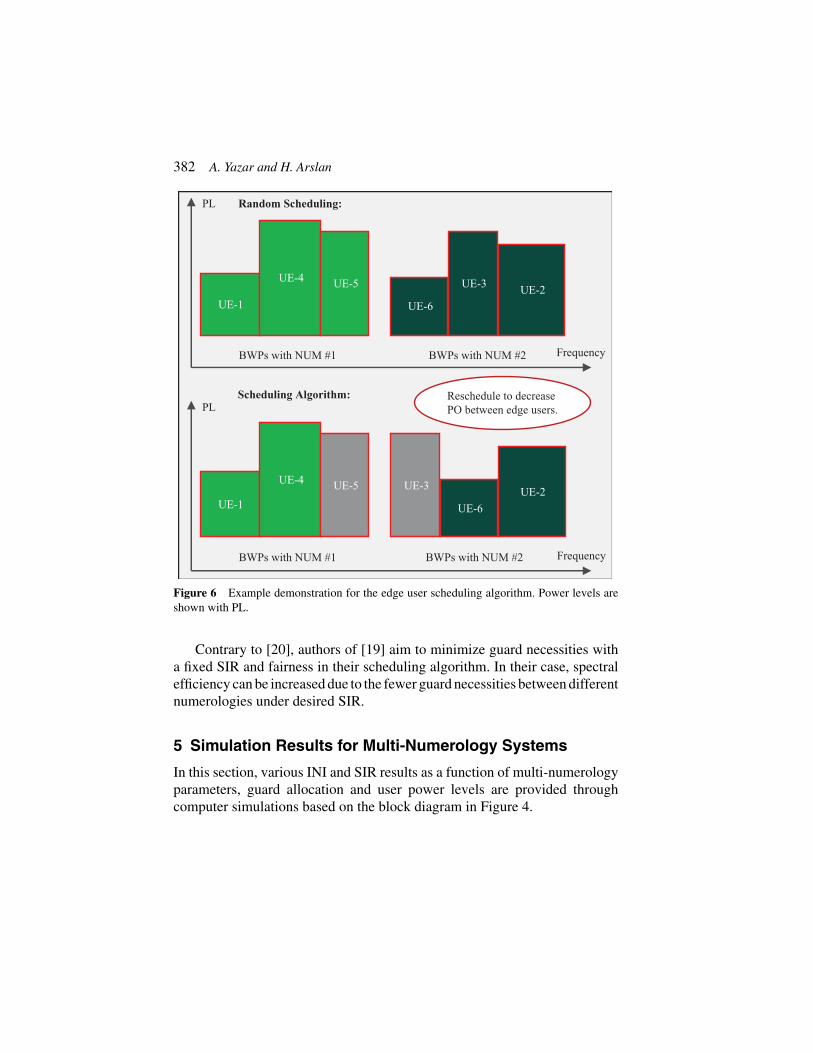
There are four cases in the simulation results presented in Figures 7 and 8.Number of usable subcarriers are half of the IFFT sizes in each case. InFigures 7 and 8, INI results are plotted like that there is not any guard bandsbetween the edge subcarriers of two numerologies when there are actuallyguard bands. The reason of this representation is to make a comparison withdifferent amount of guard bands easily.
Simulation results show that there is more INI at the edge subcarriers ofdifferent numerologies and the effect of guard bands are more prominent forthe edge subcarriers. Subblocks of the second numerology are constituted bydividing the composite signal. Hence, the symbols of the first numerologycauses an interference on the second numerology at the receiver side.
5.3 Common CP Effects
Individual CP addition causes an extra interference for the numerologywith smaller Δf as shown in Figures 7 and 8. However, in common CPimplementation, INI on every (2k)th subcarrier is zero for the numerologywith smaller Δf as it can be seen in Figure 9. It is an important advantagefor the short symbol duration numerology. Simulation results support theexplanations that are given in Section 4.2.
5.4 Power Difference Effects
In simulations, power offsets (PO) of the UEs alternate between 0 dB, 3 dB,and 7 dB. For Figure 10(a), increasing the power level of the NUM-2 edgeUE 3 dB results with 5.7 dB SIR decrement in the NUM-1 edge UE. POincrement also affects the NUM-1 inner UEs with 4.8 dB. However, thereis more than 10 dB SIR difference between the edge UE and inner UE forNUM-1.
For Figure 10(b), increasing the power level of the NUM-1 and NUM-2UEs symmetrically results with a small SIR increment in the edge UEs of twonumerologies. However, inner UEs are affected by the power levels of edgeUEs in proportion. These results show that edge user scheduling algorithmpresented in Section 4.5 is an effective solution for multi-numerology systems.

Flexible Multi-Numerology Systems for 5G New Radio 385
200 400 600 800 1000 1200 1400
Subcarrier Indices
-24
-22
-20
-18
-16
-14
-12
-10
-8
-6
-4
-2
Inte
r-N
umer
olog
y In
terf
eren
ce (
dB)
INI Estimation for Multi Numerologies
0 SC of GB for Numerology-10 SC of GB for Numerology-212 SCs of GB for Numerology-10 SC of GB for Numerology-224 SCs of GB for Numerology-10 SC of GB for Numerology-2
1000 1020 1040-20
-18
-16
-14
-12
-10
-8
-6
(a) Case 1: Guard bands are 0 kHz, 180 kHz and 360 kHz.
200 400 600 800 1000 1200 1400
Subcarrier Indices
-24
-22
-20
-18
-16
-14
-12
-10
-8
-6
-4
-2
Inte
r-N
umer
olog
y In
terf
eren
ce (
dB)
INI Estimation for Multi Numerologies
1 SC of GB for Numerology-10 SC of GB for Numerology-213 SCs of GB for Numerology-10 SC of GB for Numerology-225 SCs of GB for Numerology-10 SC of GB for Numerology-2
1000 1020 1040-20
-18
-16
-14
-12
-10
-8
-6
(b) Case 2: Guard bands are 15 kHz, 195 kHz and 375 kHz.
Figure 7 Simulation results for two different cases with different guard band amountsbetween numerologies. Numerology-1 has 15 kHz Δf and Numerology-2 has 30 kHz Δf .
386 A. Yazar and H. Arslan
200 400 600 800 1000 1200
Subcarrier Indices
-24
-22
-20
-18
-16
-14
-12
-10
-8
-6
-4
-2
Inte
r-N
umer
olog
y In
terf
eren
ce (
dB)
INI Estimation for Multi Numerologies
0 SC of GB for Numerology-10 SC of GB for Numerology-212 SCs of GB for Numerology-10 SC of GB for Numerology-224 SCs of GB for Numerology-10 SC of GB for Numerology-2
1000 1010 1020 1030 1040-18
-16
-14
-12
-10
-8
-6
-4
-2
(a) Case 3: Guard bands are 0 kHz, 180 kHz and 360 kHz.
200 400 600 800 1000 1200
Subcarrier Indices
-24
-22
-20
-18
-16
-14
-12
-10
-8
-6
-4
-2
Inte
r-N
umer
olog
y In
terf
eren
ce (
dB)
INI Estimation for Multi Numerologies
3 SC of GB for Numerology-10 SC of GB for Numerology-215 SCs of GB for Numerology-10 SC of GB for Numerology-227 SCs of GB for Numerology-10 SC of GB for Numerology-2
1000 1010 1020 1030 1040-18
-16
-14
-12
-10
-8
-6
-4
-2
(b) Case 4: Guard bands are 45 kHz, 225 kHz and 405 kHz.
Figure 8 Simulation results for two different cases with different guard band amountsbetween numerologies. Numerology-1 has 15 kHz Δf and Numerology-2 has 60 kHz Δf .

Flexible Multi-Numerology Systems for 5G New Radio 387
0
0.05
0.1
0.15
0.2
0.25INI Estimation for Multi Numerologies
200 400 600 800 1000 1200 1400
Subcarrier Indices
0 SC of GB for Numerology-10 SC of GB for Numerology-212 SCs of GB for Numerology-10 SC of GB for Numerology-224 SCs of GB for Numerology-10 SC of GB for Numerology-2
0
0.005
0.01
0.015
0.02
0.025
0.03
1005 1010 1015 1020 1025 1030 1035
(a) Numerology-1 has 15 kHz Δ f and Numerology-2 has 30 kHz Δ f.
0
0.05
0.1
0.15
0.2
0.25
0.3
0.35
0.4
0.45
0.5INI Estimation for Multi Numerologies
200 400 600 800 1000 1200
Subcarrier Indices
0 SC of GB for Numerology-10 SC of GB for Numerology-212 SCs of GB for Numerology-10 SC of GB for Numerology-224 SCs of GB for Numerology-10 SC of GB for Numerology-2
0
0.05
0.1
0.15
0.2
1010 1015 1020 1025 1030
(b) Numerology-1 has 15 kHz Δ f and Numerology-2 has 60 kHz Δ f.
EV
ME
VM
Figure 9 Simulation results for common CP implementation. Guard band amounts betweennumerologies are 0 kHz, 180 kHz and 360 kHz.

388 A. Yazar and H. Arslan
100 200 300 400 500 600 700
Subcarrier Indices
0
10
20
30
40
50
60
70
SIR
(dB
)
SIR Estimation for Multi Numerologies
Equal PLs in NUM-1Edge UE has 3 dB PO in NUM-2Equal PLs in NUM-1Edge UE has 7 dB PO in NUM-2
(a) Edge subcarriers of NUM-2 has higher PLs than the othersubcarriers in NUM-1 and NUM-2.
0
10
20
30
40
50
60
70
SIR
(dB
)
Edge UE has 3 dB PO in NUM-1Edge UE has 3 dB PO in NUM-2Edge UE has 7 dB PO in NUM-1Edge UE has 7 dB PO in NUM-2
(b) Edge subcarriers of NUM-1 and NUM-2 have higher PLsthan the inner subcarriers of NUM-1 and NUM-2. There is notany POs between the edge subcarriers.
SIR Estimation for Multi Numerologies
Subcarrier Indices100 200 300 400 500 600 700
Figure 10 Power difference analysis. NUM-1 has narrow subcarriers with 15 kHz andNUM-2 has wide subcarriers with 30 kHz.
Flexible Multi-Numerology Systems for 5G New Radio 389
6 Conclusion
Next generation communications systems including NR are evolving towardsincreased flexibility in different aspects. Enhanced flexibility is the key toaddress diverse requirements. Some parts of the 5G NR designs are left forthe implementation as long as it is transparent to the counterpart of the com-munications. NR flexibility can be exploited by finding optimal and practicalsolutions for implementation dependent parts of the 5G standardization. Theflexibility of NR brings too many open-ended research opportunities comparedto the previous cellular communications generations. Most probably, theseopportunities will increase with 5G beyond technologies.
Acknowledgement
The authors would like to thank Berker Pekoz for his valuable comments andsuggestions to improve the quality of the paper.
References
[1] 3rd Generation Partnership Project (3GPP). (2018). Evolved UniversalTerrestrial Radio Access (E-UTRA); Physical channels and modulation.Technical Specification 36.211, ver. 15.1.0.
[2] Yazar, A., and Arslan, H. (2018). A flexibility metric and optimizationmethods for mixed numerologies in 5G and beyond. IEEE Access, 6,3755–3764.
[3] Ankarali, Z. E., Peköz, B., and Arslan, H. (2017). Flexible Radio AccessBeyond 5G: A Future Projection on Waveform, Numerology, and FrameDesign Principles. IEEE Access, 5, 18295–18309.
[4] 3rd Generation Partnership Project (3GPP). (2018). NR; Physicalchannels and modulation. Technical Specification 38.211, ver. 15.2.0.
[5] Sahin, A., and Arslan, H. (2012). Multi-user aware frame structure forOFDMAbased system. In Vehicular Technology Conference (VTC Fall),IEEE (pp. 1–5).
[6] Zhang, X., Zhang, L., Xiao, P., Ma, D., Wei, J., and Xin, Y. (2018). MixedNumerologies Interference Analysis and Inter-Numerology InterferenceCancellation for Windowed OFDM Systems. IEEE Transactions onVehicular Technology.
[7] Ijaz, A., et al. (2016). Enabling massive IoT in 5G and beyond systems:PHY radio frame design considerations. IEEE Access, 4, 3322–3339.

390 A. Yazar and H. Arslan
[8] Soni, T., et al. (2018). Adaptive numerology—A solution to addressthe demanding QoS in 5G-V2X. In Wireless Communications andNetworking Conference (WCNC), (pp. 1–6). IEEE.
[9] Zhang, L., et al. (2017). Subband filtered multi-carrier systems formulti-service wireless communications. IEEE Transactions on WirelessCommunications, 16(3), 1893–1907.
[10] Abusabah, A. T., and Arslan, H. (2018). NOMA for MultinumerologyOFDM Systems. Wireless Communications and Mobile Computing,2018(1), 1–9.
[11] Nemati, M., and Arslan, H. (2018). Low ICI symbol boundary alignmentfor 5G numerology design. IEEE Access, 6, 2356–2366.
[12] Dogan, S., Tusha, A., and Arslan, H. (2018). OFDM with IndexModulation for Asynchronous mMTC Networks. Sensors, 18(4), 1280.
[13] Peköz, B., Köse, S., and Arslan, H. (2017). Adaptive windowing ofinsufficient CP for joint minimization of ISI and ACI beyond 5G. InIEEE 28th Annual International Symposium on Personal, Indoor, andMobile Radio Communications (PIMRC), (pp. 1–5). IEEE.
[14] Guan, P., et al. (2017). 5G field trials: OFDM-based waveforms andmixed numerologies. IEEE Journal on Selected Areas in Communica-tions, 35(6), 1234–1243.
[15] Iwabuchi, M., et al. (2017). 5G field experimental trial on frequencydomain multiplexing of mixed numerology. In IEEE 85th VehicularTechnology Conference (VTC Spring), 2017 (pp. 1–5). IEEE.
[16] Weitkemper, P., et al. (2016). On regular resource grid for filtered OFDM.IEEE Communications Letters, 20(12), 2486–2489.
[17] Zaidi, A. A., et al. (2016). Waveform and numerology to support 5Gservices and requirements. IEEE Communications Magazine, 54(11),90–98.
[18] Demmer, D., et al. (2018). Analytical study of 5G NR eMBB co-existence. arXiv preprint. Available online at: arXiv:1805.05591.
[19] Demir,A. F., andArslan, H. (2017). The impact of adaptive guards for 5Gand beyond. In IEEE 28th Annual International Symposium on Personal,Indoor, and Mobile Radio Communications (PIMRC), (pp. 1–5). IEEE.
[20] Yazar, A., and Arslan, H. (2018). Fairness-Aware Scheduling inMulti-Numerology Based 5G New Radio. Available online at:arXiv:1806.04072.
[21] A. Gonzalez et al. (2017). Resource Allocation for Block-Based Multi-Carrier Systems Considering QoS Requirements.In IEEE Conference onGlobal Communications (GLOBECOM), Singapore.
Flexible Multi-Numerology Systems for 5G New Radio 391
[22] Akhtar, A., and Arslan, H. (2018). Downlink resource allocation andpacket scheduling in multi-numerology wireless systems. In WirelessCommunications and Networking Conference Workshops (WCNCW),(pp. 362–367). IEEE.
[23] You, L., et al. (2018). Resource Optimization with Flexible Numerologyand Frame Structure for Heterogeneous Services. Available online at:arXiv:1801.02066.
[24] Jeon, J. (2018). NR wide bandwidth operations. IEEE CommunicationsMagazine, 56(3):42–46.
[25] Parkvall, S., et al. (2017). NR: the new 5G radio access technology. IEEECommunications Standards Magazine, 1(4), 24–30.
[26] Lin, X. et al. (2018). 5G New Radio: Unveiling the Essentials ofthe Next Generation Wireless Access Technology. Available online at:arXiv:1806.06898.
[27] Zaidi,A.A., et al. (2018). OFDM Numerology Design for 5G New Radioto Support IoT, eMBB, and MBSFN. IEEE Communications StandardsMagazine, 2(2), 78–83.
[28] 3rd Generation Partnership Project (3GPP). (2018). NR; User Equipment(UE) radio transmission and reception; Part 1: Range 1 Standalone.Technical Specification 38.101-1, ver. 15.1.0.
[29] 3rd Generation Partnership Project (3GPP). (2018). NR; User Equipment(UE) radio transmission and reception; Part 2: Range 2 Standalone.Technical Specification 38.101-2, ver. 15.1.0.
[30] 3rd Generation Partnership Project (3GPP). (2018). NR; User Equipment(UE) radio transmission and reception; Part 3: Range 1 and Range2 Interworking operation with other radios. Technical Specification38.101-3, ver. 15.1.0.
[31] 3rd Generation Partnership Project (3GPP). (2017). Study on new radioaccess technology Radio interface protocol aspects. Technical Report38.804, ver. 14.0.0.
[32] 3rd Generation Partnership Project (3GPP). (2018). NR; Base Station(BS) radio transmission and reception. Technical Specification 38.104,ver. 15.1.0.
[33] 3rd Generation Partnership Project (3GPP). (2018). NR; Physical layerprocedures for control. Technical Specification 38.213, ver. 15.2.0.
[34] 3rd Generation Partnership Project (3GPP). (2018). NR; Overall descrip-tion; Stage-2. Technical Report 38.300, ver. 15.2.0.
[35] 3rd Generation Partnership Project (3GPP). (2018). General aspects forUE RF for NR. Technical Report 38.817-01, ver. 2.0.0.
392 A. Yazar and H. Arslan
[36] 3rd Generation Partnership Project (3GPP). (2017). Study on new radioaccess technology Physical layer aspects. Technical Report 38.802, ver.14.2.0.
[37] 3rd Generation Partnership Project (3GPP). (2017). Study on new radioaccess technology. Technical Report 38.912, ver. 14.1.0.
[38] 3rd Generation Partnership Project (3GPP). (2018). NR; Physical layer;General description. Technical Specification 38.201, ver. 15.0.0.
[39] Celebi, M. B., and Arslan, H. (2015). Theoretical analysis of the co-existence of LTE-a signals and design of an ML-SIC receiver. IEEETransactions on Wireless Communications, 14(8), 4626–4639.
[40] Lorca, J. (2015). Cyclic prefix overhead reduction for low-latencywireless communications in OFDM. In IEEE 81st Vehicular TechnologyConference (VTC Spring), (pp. 1–5). IEEE.
[41] Sahin, A., and Arslan, H. (2011). Edge windowing for OFDM basedsystems. IEEE Communications Letters, 15(11), 1208–1211.
Biographies
Ahmet Yazar received his B.Sc. degree in electrical engineering from Eskise-hir Osmangazi University, Eskisehir, Turkey in 2011 and M.Sc. degree inelectrical engineering from Bilkent University, Ankara, Turkey in 2013. From2011 to 2013, he was a member of the Bilkent Signal Processing Groupwhere he studied Wavelet Theory and some other signal processing methodsin various pattern recognition projects. In 2013, he joined the Informationand Communication Technologies Authority and he worked in SpectrumManagement Department. At the beginning of 2014, he was appointed underthe Presidency of Telecommunication and Communication for one year. Heis currently pursuing the Ph.D. degree as a member of the Communications,

Flexible Multi-Numerology Systems for 5G New Radio 393
Signal Processing, and Networking Center (CoSiNC) at Istanbul MedipolUniversity. His current research interests are flexible waveform systems andmulti-numerology structures.
HuseyinArslan received the B.S. degree from Middle East Technical Univer-sity, Ankara, Turkey, in 1992, and the M.S. and Ph.D. degrees from SouthernMethodist University, Dallas, TX, USA, in 1994 and 1998, respectively.From 1998 to 2002, he was with the Research Group, Ericsson Inc., NC,USA, where he was involved with several projects related to 2G and 3Gwireless communication systems. Since 2002, he has been with the ElectricalEngineering Department, University of South Florida, Tampa, FL, USA. Hehas also been the Dean of the College of Engineering and Natural Sciences,Istanbul Medipol University, since 2014. He was a part-time Consultantfor various companies and institutions, including Anritsu Company, MorganHill, CA, USA, and The Scientific and Technological Research Council ofTurkey (TUBITAK). His research interests are in physical layer security,mmWave communications, small cells, multicarrier wireless technologies,co-existence issues on heterogeneous networks, aeronautical (high-altitudeplatform) communications, in vivo channel modeling, and system design.
